
Research on Electric Vehicle Rollover Prevention System Based on Motor Speed Control


College of Engineering, Beijing Forestry University, Beijing 100083, China
*
Author to whom correspondence should be addressed.
World Electr. Veh. J. 2021, 12(4), 195; https://doi.org/10.3390/wevj12040195
Submission received: 6 September 2021
/
Revised: 1 October 2021
/
Accepted: 14 October 2021
/
Published: 18 October 2021
Abstract
:Vehicle driving safety is an important performance indicator for vehicles, and there is still much room for development in the active safety control of electric vehicles. A vehicle rollover is an important road traffic safety problem, as rollover accidents cause serious casualties and huge economic losses. It is very easy for vehicles in high-speed sharp turns or high-speed overtaking to roll over; in order to improve the vehicle in these conditions with the anti-rollover stability, this study proposed a real-time motor control strategy, mainly through the acquisition of vehicle attitude data and the use of multi-sensor fusion on the vehicle running state for real time. The lateral load transfer rate was used as the vehicle rollover evaluation index, and the test results indicate that when the real-time rollover index exceeds the set limit safety threshold, the motor speed is reduced through active control so that the vehicle avoids rollover accidents, or the risk of rollover is reduced. The STM32F103RET6 was used as the main chip for hardware design, control board fabrication, control program software design, and joint testing of software and hardware. The tests and data analysis prove that the motor control strategy is reliable in real time and can significantly improve the active safety of electric vehicles.
1. Introduction
The safety performance of vehicles on the road is an important performance indicator in the evaluation of vehicle performance [1]. With the increasing complexity of the traffic environment, traffic accidents have increased significantly, causing significant damage to people both financially and physically. According to the National Highway Traffic Safety Administration (NHTSA), rollover accidents are the second-highest percentage of car accidents after collisions [2], with rollover accidents accounting for about 17.7% of all traffic fatalities. Nowadays, more attention is being paid to the safety performance of vehicles. Anti-rollover performance of vehicles is one of the indicators used in the performance evaluation of new vehicles in the United States. In the study of automotive safety, rollover stability is the main mandated item requiring mandatory testing. Automotive safety is divided into two categories: active and passive safety [3]. Passive safety can only mitigate damage after an accident, not prevent it from happening. Scholars are now focusing their research and development on active safety, which enables cars to take proactive action before an accident occurs.
Vehicle rollovers are divided into two categories: untripped rollover and tripped rollover. Domestic and international survey data show that the proportion of untripped rollovers is twice as high as that of tripped rollovers [4]. Therefore, active anti-rollover control for non-tripping rollovers is of great relevance to reduce rollover accidents and protect people’s lives.
It is clear from researchers’ investigations that a significant influence on rollover accidents is manoeuvring—cars turning or momentarily failing to steer at high speeds are the most significant cause of rollover accidents. Approximately 40% of fatal rollover accidents are associated with speeding, with fatal rollovers occurring at speed limits of 55 mph or higher [5]. Li et al. used Trucksim software to model a three-degree-of-freedom passenger vehicle and concluded from simulation tests that speed is an important influence in rollover accidents of vehicles and that the likelihood of rollover increases with increasing speed [6]. The anti-rollover test conducted by Wang et al. on vehicles in mountainous areas showed that increasing the vehicle speed would lead to a decrease in vehicle stability, and when the vehicle was about to roll over, slowing down the brakes to reduce the vehicle speed could avoid rollover and improve the stability of the vehicle driving [7].
The speed of an electric vehicle is determined by the drive motor. There are few studies related to the rollover stability of electric vehicles by scholars at home and abroad, and the control strategy of preventing vehicle rollover directly by controlling the drive motor speed is even less involved in the research. Yuan et al. were able to predict the risk of rollover of electric vehicles with hub motors by establishing a predictive model of stability and using the function that the torque of all wheels can be adjusted individually [8]. Ma et al. carried out actively controlled anti-rollover of electric vehicles by regulating the transverse swing torque [9]. Liu et al. studied the rollover stability of wheel hub motors and applied a new integrated chassis for the improvement of the anti-rollover system to enhance the rollover stability of wheel hub electric vehicles [10].
Shim and Ghike summarise four basic approaches commonly used for anti-roll control: active steering, differential braking, active lateral stabiliser bars, and active/semi-active suspension [11]. In the past, researchers have mostly focused on these four methods to control vehicle rollover, while for electric vehicles, where the vehicle speed is determined by the drive motor, less research is involved in studying the control strategy to prevent vehicle rollover directly by controlling the drive motor speed. Achieving the purpose of improving the active safety of electric vehicles through motor control strategies, improving the instability factors generated on the body structure of electric vehicles, and improving the performance of electric vehicles are of great research significance to the development of today’s electric vehicle industry.
Islam et al. designed an active steering controller that captured steering angle data to input into a model to enhance stability and control [12]. Wang et al. used differential braking and active steering technologies to fuse and design a controller that matched the turning angle of the vehicle with the braking force of the wheels to prevent rollover accidents from occurring [13]. He et al. used differential braking technology for control simulation, and the results showed that the differential braking technology reduced the lateral acceleration of the vehicle and could play a rollover prevention role [14]. Chen et al. designed an anti-rollover control system based on the performance of a semi-active suspension, with rollover time TTR as the judging index [15]. Today, several of these techniques are more advanced and effective, but they still have shortcomings. Active steering techniques have the potential to cause drivers to deviate from their set course, so they cannot be used in sudden avoidance situations. Differential braking techniques are easily influenced by the traction forces on the ground and the performance of the brakes. The active suspension technology is not sufficiently real time and has a delayed response.
This paper proposes a generic real-time motor control strategy that uses multi-sensor fusion and pulse width modulation (PWM) to automatically control the speed of the electric vehicle drive motor when the vehicle is in a sideways and dangerous driving condition to prevent rollover accidents.
A three-degree-of-freedom vehicle rollover dynamics model was developed, rollover evaluation indicators and safety thresholds were selected, and the working principle and detailed control scheme of the motor speed control strategy were given. The hardware platform and the software program of the anti-rollover control strategy were designed. A control board with PWM output, WIFI, a six-axis attitude sensor, an optical encoder, and other module interfaces were designed and built with STM32 as the main control chip. The software design for rollover warning and motor active speed reduction was completed, including the study of warning algorithm, PWM speed regulation, rollover evaluation index calculation, interface configuration, communication mode, etc.
Using a self-developed 4WD cart as a testing platform, the hardware and software systems were installed on the cart, and a fishhook test scheme was set up for comparison tests. The tests showed that when the anti-rollover control system was switched off, the cart would roll over when turning at a certain speed; when the anti-rollover system was switched on, the cart would not roll over when driving under the same working conditions. The test results verify the real-time applicability and effectiveness of the anti-rollover control strategy of the vehicle.
2. Materials and Methods
2.1. Roll Dynamic Model
To achieve active rollover control of the vehicle, a three-degree-of-freedom rollover dynamics model of the electric vehicle including lateral, transverse, and lateral tendencies was developed, as shown in Figure 1 [16].
In order to make the model easy to solve, the following simplifications were made to the car dynamics characteristics: the wheels were assumed to be symmetrical about the x-axis, there was no horizontal motion along the z-axis and no rotational motion around the y-axis, and the deformation of the tires and suspension, as well as the aerodynamic effects, were neglected. According to this model, the following relations were obtained:
① Equation for the dynamics of transverse motion:
where m—the mass of the vehicle; —the spring-loaded mass; h—the height difference between the centre of mass of the vehicle and the centre of sway; —the lateral forces of the front and rear wheels; —lateral camber angle; —the lateral deflection stiffness of the front and rear wheels.
② Dynamic equation for the motion of a transverse pendulum:
where —the inertia of rotation around the x-axis; —the distance between the centre of mass and the forward and backward axes; —the angular velocity of the transverse pendulum.
③ Kinetic equation for lateral tilting motion:
where —rotational inertia about the x-axis; c—equivalent damping coefficient of the suspension; —suspension lateral sway stiffness; g—acceleration of gravity.
The lateral acceleration of the vehicle can be found as follows:
where —the speed of the car laterally; —the speed of the car.
It is clear from the equation that as the vehicle speed u decreases, the lateral acceleration and the lateral lean angle decrease and the likelihood of the vehicle rolling over is reduced.
2.2. Vehicle Rollover Evaluation Indicator
The three common evaluation indicators of vehicle rollover, in general, are lateral acceleration, maximum lateral tilt angle, and lateral load transfer rate (LTR). Since LTR is a dynamic indicator, a dynamic model can be established to monitor the driving state of the vehicle with a transient response, the rollover evaluation indicator used in this study was the lateral load transfer rate (LTR) [17].
The lateral load transfer rate (LTR) is expressed as the sum of the ratio of the difference between the vertical loads of the wheels on each side of the vehicle. As the pressure on the wheels on each side of the vehicle differs when the vehicle is tilted sideways, this can be calculated by the following equation [18]:
where —the sum of the vertical loads of the two wheels on the left side; —the sum of the vertical loads of the two wheels on the right side. The value of LTR ranges from −1 to 1. When LTR = −1 or 1, the left- or right-side wheels of the vehicle are completely off the ground. As this method requires the measurement of the wheel support reaction force, it is difficult to obtain this parameter in real time, so the calculation of the dynamic lateral load transfer rate is proposed as the following equation for the moment balance containing the vertical force of the tire and the lateral sway moment of the suspension [19]:
From Equations (7) and (8), the dynamic lateral load transfer rate expression is obtained as
where —the equivalent damping factor of the suspension; —sway stiffness of the suspension; m—total mass; L—wheelbase; g—gravitational acceleration; —lateral inclination; —lateral camber speed.
The lateral load transfer rate calculated by this equation is more real time and dynamic, and the parameters are more accurately obtained. Once the parameters of the vehicle have been determined, and the attitude sensor detects that the vehicle is returning real-time data on lateral lean angle and lateral lean angle velocity, the lateral load transfer rate can be calculated for each instant by this equation.
In order to ensure the predictability of the control, the control model for the study was built in Simulink based on the results of the joint simulation that CarSim and Simulink conducted prior to the hardware and software design and testing in this study, Typical rollover test conditions include fishhook test, double shift test, and steady-state slew test, where the fishhook test and double shift test can reach LTR of 0.8 without reaching the rollover state, but the steady-state slew test will have an unstable driving condition of rollover at around 0.65. Therefore, in order to ensure the safety and stability of the actual fishhook test, the alarm safety threshold for the control system was selected to be 0.65, and the automatic control system safety threshold was 0.7, i.e., when |LTR| = 0.65, the system issues an alarm and when |LTR|= 0.7, the system carries out active control of the vehicle speed reduction; these two thresholds have a certain safety margin from the rollover threshold value of |LTR| = 1. |LTR| = 1, which indicates that one side wheel is completely off the ground.
2.3. Attitude Solving
The attitude solution in rollover control has an initial angle acquisition and update algorithm, where the original attitude angle is first obtained and then the quaternion algorithm is chosen to update the attitude.
Definition , , are the rotation angles around the Z-axis, Y-axis, and X-axis, respectively, or yaw, pitch, and roll if expressed in terms of Tait–Bryan angles [20]. Tait-Bryan angles are shown in Figure 2.
① Definition of quaternions:
A quaternion can be constructed by rotating the axis and the angle of rotation about that axis.
where α is the angle of rotation about the axis of rotation, and , , and are the components of the axis of rotation in the x, y, and z directions (from which the axis of rotation is determined).
② Conversion of Euler angles to quaternions:
③ Conversion of quaternions to Euler angles:
This equation can be used to find the roll angle, which, together with the raw data from the gyroscope (roll angle velocity), is used as input data for the vehicle anti-roll control system [21].
2.4. Driving Motor Control-Strategy-Based Anti-Rollover
According to the vehicle dynamics model, the lateral acceleration of the vehicle centre of mass is determined by the longitudinal travel speed and lateral travel acceleration as well as the yaw rate, so if the longitudinal travel speed of the vehicle is reduced, the lateral acceleration of the vehicle centre of mass can be directly reduced from the root cause, thus achieving the purpose of suppressing or avoiding vehicle rollover [22].
According to Equation (9), the vehicle’s rollover evaluation index LTR needs real-time rollover angle and rollover angle speed; therefore, the MPU6050 sensor is used to obtain the input data for the control algorithm, the X-axis angular speed in the original data it measures is the rollover angle speed, and the cross-roll angle (roll) obtained through attitude solution is the rollover angle. The two data are transmitted to the microcontroller synchronously for the calculation of the LTR dynamic value. When the absolute value of the dynamic transverse load transfer rate reaches 0.65, close to the limit threshold, the buzzer generates an alarm sound signal, and when the limit threshold of 0.7 is reached, a drive motor speed control signal is sent out to control the motor controller to reduce the motor speed, so that the car can return to a safe driving state smoothly and achieve the purpose of avoiding rollover [23]. The speed sensor acquires the motor speed in real time and transmits the acquired data to the microcontroller as closed-loop feedback for the motor control algorithm. The block diagram is shown in Figure 3.
First, the hardware platform was designed, the STM32F103RET6 was selected as the main control chip, and the minimum system circuit of the chip was designed. Then, the MPU6050 was selected for the attitude sensor, the HJ-IR6 optical encoder was selected for the speed module, the ATK-ESP8266 was selected for the WIFI module, and the peripheral circuits were designed according to the sensors and other control modules. Next, the PCB board was packaged and produced, and the hardware platform of the anti-rollover control system was completed with the welding of components. In the above hardware platform to carry out the design of software programming, the attitude of the car to solve, the obtained Euler angle, and side tilt angle speed were used as inputs of the vehicle rollover warning algorithm and inserted in the program to assess rollover evaluation index; PWM pulse width modulation technology was used to control the motor speed—depending on the selection of speed sensor design, speed algorithm, and the measured speed as the motor speed control feedback, real-time monitoring of vehicle speed changes.
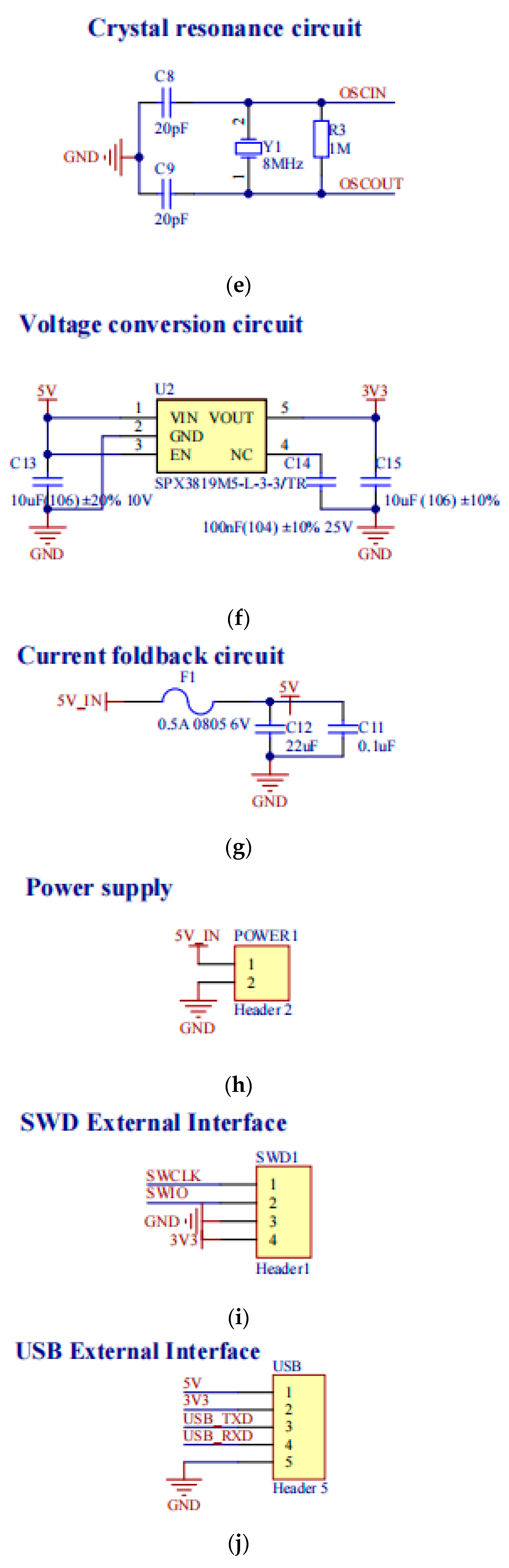
2.5. Circuit Design
The development board designed in this paper used the STM32F103RET6 chip from ST. This chip contains up to 64 KB of embedded SRAM and 512 KB of FLASH, 8 timers, as well as SPI, IIC, USB, CAN, SDIO, FSMC interfaces, a total of 64 pins, and can output 5 V and 3.3 V. The chip MCU requires a minimum circuit system design, which is the module that guarantees the proper operation of the microcontroller. Development boards for microcontrollers are generally based on a minimal system with peripheral modules to achieve various functions. The minimum circuit system of the main control chip MCU includes the power supply module (power inlet, power filter, voltage conversion, over-current protection), reset circuit, start-up mode circuit, and crystal oscillator circuit [24].
Peripheral system circuit design included SWD burn-in program circuit design, USB transmission circuit design, WIFI module interface design, MPU6050 module interface design, buzzer circuit design, speed measurement module interface design, and PWM output module interface design.
The schematic diagram of each part is shown in Figure 4.
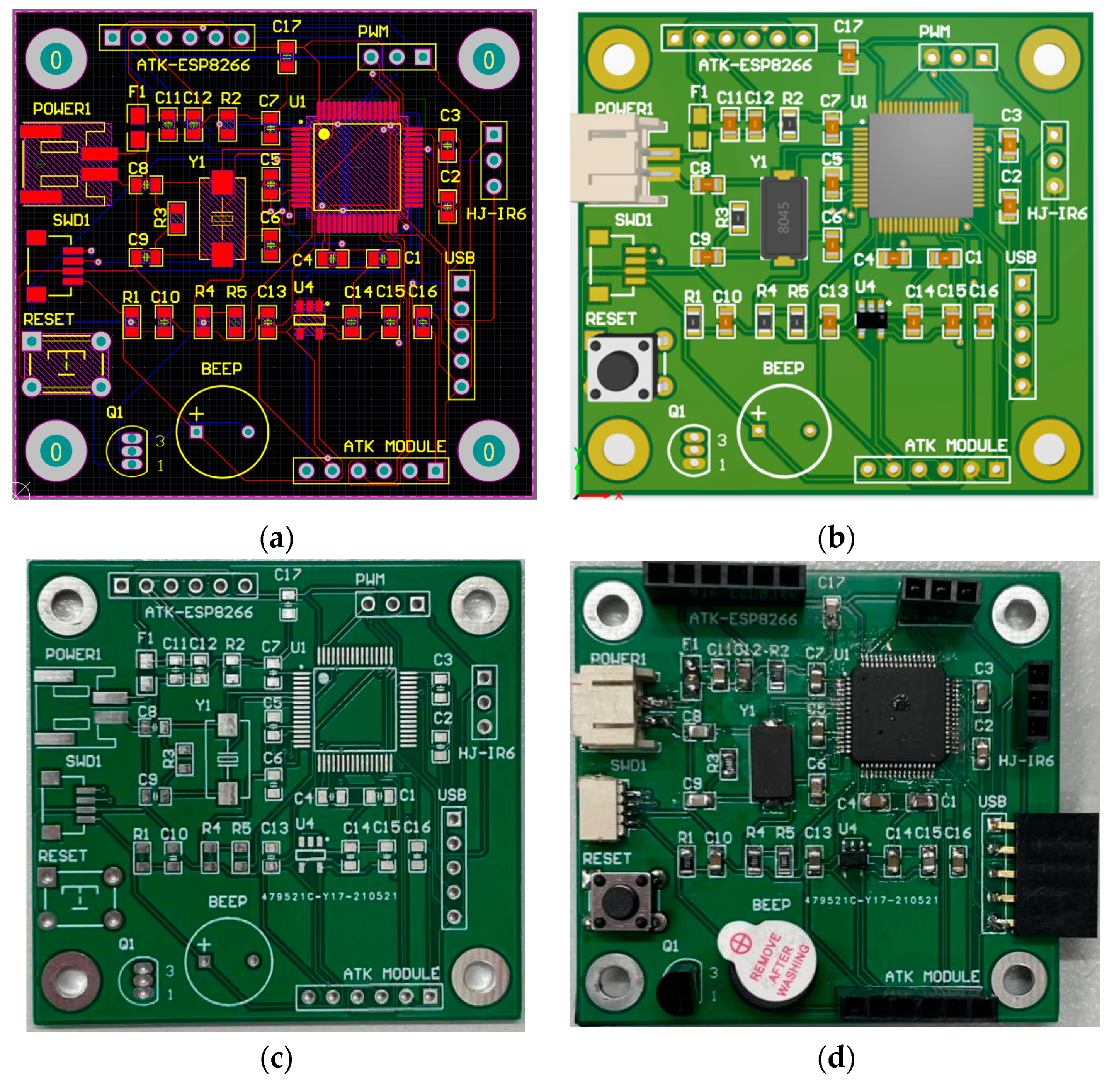
2.6. PCB Packaging and Fabrication
Altium Designer was used to design and produce PCBs by first selecting the right package for the device, then importing the schematic into the PCB design, laying out the wiring and copper cladding, as well as making the PCB board and soldering the components.
Figure 5 show a preview of the layout and wiring, a preview of the PCB, a physical view of the control board before soldering, and a physical view of the control board after soldering.
2.7. Experimental Analysis
In this paper, a brushless RC 4WD vehicle with a speed capable of 50 km/h-70 km/h was selected. RC 4WD body size is 32 × 20 × 15.5 cm, body battery is 7.4 V/650 mA lithium battery, its body weight is 979.7 g, and its tire diameter is 84 mm. This RC vehicle uses a 2838 brushless motor as the motor drive, a rudder to control the direction, a 120 A brushless ESC to control the motor and rudder. The model of the brushless motor is 2838; the rated voltage is 24 V, the load power is 14.6 W, the shaft diameter is 3.175 mm, the circle diameter is 28 mm, the height is 39 mm, and the speed can reach 5800 rpm. The steering gear is a 2.2 KG metal three-wire steering gear. It has a suspension, differential, high torque servo, hydraulic shock absorbers, etc. The components of the vehicle are relatively complete and high performance, and this vehicle was used to simulate a real vehicle for testing; feasibility was good. By modifying the 4WD wiring, the motor and servo were taken over and controlled by a control board of this design, an optical encoder module was installed on the rear axle of the vehicle for speed measurement, the control board was mounted and fixed above the centre of mass of the vehicle, and the sensor modules were connected.
The designed software program was burned into the STM32 chip, and a test program was designed to verify the anti-rollover control strategy of the car. A comparison test method was used to set up two sets of tests for control, with the test group having the anti-rollover control system switched on and the control group having the anti-rollover control system switched off.
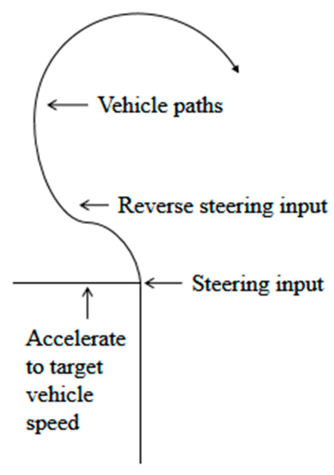
A schematic diagram of the arrangement of the Fishhook test in accordance with 49 CFR part 575 is shown in Figure 6 [25].
The test car was set to gradually accelerate from a standstill to 13 m/s (47 km/h) by means of a PWM program. The trolley turned and drove according to the prescribed trajectory. The test site layout is shown in Figure 7.
The test group switched on the vehicle’s anti-roll control system, and the roll angle data returned by the MPU6050 attitude sensor was used as input to the rollover warning algorithm, which activated the rollover warning and anti-rollover active control systems. The control group turned off the early warning and active control and controlled the vehicle to follow the same speed and trajectory as the test group.
The following test data were saved in the host computer for each test: the vehicle speed, the lateral load transfer rate (LTR) data, as well as the lateral camber and lateral acceleration data of the vehicle, and the observation of the vehicle’s movement.
3. Results
The test obtained the data of side camber, vehicle speed, and LTR in real time using the upper computer, imported the data into an Excel table, and plotted the curve of side camber, vehicle speed, and LTR with time, as shown in Figure 8, Figure 9 and Figure 10.
As can be seen from Figure 8, Figure 9 and Figure 10, in the uncontrolled group with the active anti-roll control system switched off, when the side tilt angle exceeds 25.9° at about 7 s and continues to increase beyond 30°, active deceleration system not working, and LTR continues to increase after exceeding 0.7; the outcome is the trolley’s unstable driving, with one side of the wheel off the ground. Additionally, in the control group, in which the active anti-rollover control system is switched on, when the trolley travels at 13 m/s (47 km/h) in the fishhook slew test, the maximum side tilt angle at the turn reaches 25.9°, and the trolley tilts visibly sideways. Analysing the data graph, when the time is 6.5 s, the LTR value exceeds the warning threshold of 0.65, at which point the warning procedure is triggered, and the buzzer sounds an alarm. When the LTR exceeds the active control threshold of 0.7 at 7 s, the maximum sway angle reaches 25.9°, as can be seen from Figure 8. The speed curve in Figure 9 shows that the active control system starts to slow down the motor from 13 m/s (47 km/h) until the speed stabilises around 3 m/s (10 km/h), and the LTR value is reduced to a safe value accordingly. After the buzzer “drip” alarm is heard, it was observed that the speed of the car noticeably reduces, the side tilt angle is reduced, and the car is restored to a stable state.
The control system is not triggered in 2–7 s, and the vehicle speed remains the same, with and without control in the same conditions. The curve of this process is not completely consistent because the actual test site is in an outdoor environment. The test car is inevitably affected by wind speed, ground flatness, unstable fluctuations within the sensor’s tiny error range, and other uncontrollable minor external factors. Therefore, the actual roll angle and the LTR change are different due to interference, but the changing trend in the overall curve is the same, which has no influence on the analysis of the test results.
According to the analysis of the test data and curve, when the vehicle is in a rollover dangerous driving condition, the control system quickly reacts and controls the motor speed down in time, thus reducing the vehicle driving speed and making the vehicle driving process of the side tilt angle and LTR value correspondingly reduce, then the vehicle gradually restores the smooth driving state; thus, the test well proves that the automatic anti-rollover control strategy of this study can effectively prevent the occurrence of vehicle rollover or reduce the risk of rollover.
The control strategy, when applied to actual electric vehicles, only requires different motor control methods for different types of electric vehicle drive motors. The acquisition of data and the calculation of rollover evaluation indicators can be equivalent to the application in this experiment, and the overall prevention alarm and rollover control method is universally applicable to all types of electric vehicles, enabling real-time and effective prevention and reduction in the risk of electric vehicle rollover accidents.
4. Conclusions
This paper proposed an anti-rollover control strategy based on a pure electric vehicle, designed and produced a PCB circuit board, designed an STM32 software program on this hardware platform, combined vehicle rollover warning and active control of vehicle speed, developed an anti-rollover strategy based on motor speed control with LTR as the rollover evaluation index, and conducted a small vehicle test. The results proved that both the warning and control are timely and effective, assisting the driver in anticipating rollover accidents and actively reducing speed to prevent them. The study reveals that when the warning threshold set by the rollover evaluation index is reached, the driver is alerted by an audible and visual alarm, and when the rollover limit threshold is reached, the motor speed active control system intervenes to reduce the motor speed through the main control chip control until the real-time LTR value is less than the rollover threshold so that the vehicle avoids rollover or the risk of rollover is reduced, thus improving the active safety of the vehicle.
Author Contributions
Methodology, hardware design and production, software, formal analysis, data curation, writing—original draft preparation, writing—review and editing, M.D.; investigation, validation, visualisation, M.D., Y.F., and D.Y.; resources, supervision, project administration, funding acquisition, Q.W. All authors have read and agreed to the published version of the manuscript.
Funding
This paper is supported by the National Natural Science Foundation of China (Grant No. 51475255).
Conflicts of Interest
The authors declare no conflict of interest.
References
- National Highway Traffic Safety Administration. Available online: https://crashstats.nhtsa.dot.gov (accessed on 21 September 2020).
- Shao, K. Theoretical Research on Vehicle Rollover Mechanism and Active Steering Rollover Prevention Control. Doctoral Thesis, Hefei University of Technology, Hefei, China, 2019. [Google Scholar]
- Liu, L.F. The Research on Anti-Roll Control Based on Differential Braking. Master’s Thesis, Yanshan University, Qinhuangdao, China, 2016. [Google Scholar]
- Palkovic, L.; Semsey, A.; Gerum, E. Roll-Over Prevention System for Commercial Vehicles Additional Sensorless Function of the Electronic Brake System. Veh. Syst. Dyn. 1999, 32, 285–297. [Google Scholar] [CrossRef]
- Bai, T.Y. Research on Active Steering Based on Fuzzy Logic Controller of Genetic Algorithm Optimization. Intern. Combust. Engine Parts 2019, 15, 47–49. [Google Scholar]
- Li, S.C.; Yang, F.Y. Research on Anti-rollover Control of Passenger Car. Mag. Equip. Mach. 2020, 4, 37–43. [Google Scholar]
- Wang, H.L.; Shi, Z.K. Rollover Analysis for Vehicle on Mountain Roads. J. Transport. Inf. Saf. 2013, 31, 93–97. [Google Scholar]
- Yuan, L.; Liu, Z.Y.; He, Z. Yaw stability Control for Rollover Prevention of IWMEV. Control Theory Committee of the Chinese Society of Automation, Chinese Society of Systems Engineering. In Proceedings of the 35th Chinese Control Conference (F), Control Theory Committee of the Chinese Society of Automation, Chinese Society of Systems Engineering: Control Theory Committee of the Chinese Society of Automation, Chengdu, China, 27–29 July 2016. [Google Scholar]
- MA, B.; Chen, Y.; Gong, G.Q. Study of Roll Stability Control of the Electric School Bus. Comput. Simul. 2017, 34, 144–149. [Google Scholar]
- Liu, W.; He, H.W.; Sun, F.C.; Lv, J.Y. Integrated chassis control for a three-axle electric bus with distributed driving motors and active rear steering system. Veh. Syst. Dyn. 2017, 55, 601–625. [Google Scholar] [CrossRef]
- Shim, T.; Ghike, C. Understanding the limitations of different vehicle models for roll dynamics studies. Veh. Syst. Dyn. 2007, 45, 191–216. [Google Scholar] [CrossRef]
- Islam, M.M. Road vehicle rollover avoidance using active steering controller. In Proceedings of the 14th International Conference on Computer and Information Technology (ICCIT 2011), Dhaka, Bangladesh, 22–24 December 2011; pp. 298–302. [Google Scholar] [CrossRef]
- Wang, N.; Fang, S.; LI, J.; Yuan, F. Study on the optimal control of bus rollover based on active steering and differential braking. J. Shandong Univ. Technol. (Nat. Sci. Ed.) 2018, 32, 26–30. [Google Scholar]
- He, F.; Yang, L.; Liu, Z. Study on Differential-Braking-Based Vehicle Dynamics Control with Rollover Prevention. Mod. Mach. 2003, 5, 31–33. [Google Scholar]
- Chen, J. Research on Active Anti-Rollover Control of Heavy-Duty Truck Based on Dynamic TTR. Master’s Thesis, Guizhou University, Guiyang, China, 2017. [Google Scholar]
- He, J.R. Research on Rollover Warning System for Light Forest Fire-Fighting Truck Based on TTR. Master’s Thesis, Beijing Forestry University, Beijing, China, 2019. [Google Scholar]
- Rath, J.; Defoort, M.; Veluvolu, K.C. Rollover index estimation in the presence of sensor faults, unknown inputs, and uncertainties. IEEE Trans. Veh. Technol. 2016, 17, 2949–2959. [Google Scholar] [CrossRef]
- Phanomchoeng, G.; Rajamani, R. New rollover index for the detection of tripped and untripped rollovers. IEEE Trans. Ind. Electron. 2013, 60, 4726–4736. [Google Scholar] [CrossRef]
- Bijoy, K.; Bhagya, A. Feedback Linearization of the Rotational Dynamics of a Flock of Target Tracking Visual Sensor Array using Tait-Bryan Parameterization. IFAC PapersOnLine 2019, 51, 258–263. [Google Scholar]
- Chai, J.; Zhao, T.; Gui, X. Multi-Objective Optimization Design of Permanent Magnet Torque Motor. World Electr. Veh. J. 2021, 12, 131. [Google Scholar] [CrossRef]
- Zhang, C.; Chang, B.; Zhang, R.; Wang, R.; Wang, J. Observation of Dynamic State Parameters and Yaw Stability Control of Four-Wheel-Independent-Drive EV. World Electr. Veh. J. 2021, 12, 105. [Google Scholar] [CrossRef]
- Ricciardi, V.; Ivanov, V.; Dhaens, M.; Vandersmissen, B.; Geraerts, M.; Savitski, D.; Augsburg, K. Ride Blending Control for Electric Vehicles. World Electr. Veh. J. 2019, 10, 36. [Google Scholar] [CrossRef] [Green Version]
- Nevin, F.; Hany, F.; Sohrab, M. Performance Evaluation of Electric Vehicle Model under Skid Control Technique. World Electr. Veh. J. 2021, 12, 83. [Google Scholar]
- Nie, Y.T.; Dong, C. Microcomputer Energy Saving Control System for Electric Vehicles Under Artificial Intelligence. IOP Conf. Ser. Earth Environ. Sci. 2021, 769. [Google Scholar] [CrossRef]
- Moein, M.; Timber, Y.; Lucian, B. Implementation of Experiential Learning for Vehicle Dynamic in Automotive Engineering: Roll-over and Fishhook Test. Procedia Manuf. 2019, 32, 768–774. [Google Scholar]
Figure 1.
Three-degree-of-freedom cartwheel dynamics model: (a) top view; (b) rear view.

Figure 2.
Tait–Bryan angles.

Figure 3.
Rollover control strategy.

Figure 4.
Circuit schematic: (a) chip; (b) reset circuit; (c) start-up model; (d) power filter circuit; (e) crystal resonance circuit; (f) voltage conversion circuit; (g) current foldback circuit; (h) power supply; (i) SWD external interface; (j) USB external interface; (k) MPU6050 external interface; (l) ATK-ESP8266 WIFI; (m) PWM external interface and interface of speed measuring module; (n) buzzer alarm circuit.


Figure 5.
Preview and physical view of the control board: (a) preview of the layout wiring; (b) preview of the PCB; (c) physical view of the control board before welding; (d) physical view of the control board after welding.
Figure 5.
Preview and physical view of the control board: (a) preview of the layout wiring; (b) preview of the PCB; (c) physical view of the control board before welding; (d) physical view of the control board after welding.

Figure 6.
Schematic diagram of layout path of fishhook testing ground.

Figure 7.
Fishhook test site layout: (a) full view of the fishhook test; (b) partial view of fish hook test.
Figure 7.
Fishhook test site layout: (a) full view of the fishhook test; (b) partial view of fish hook test.

Figure 8.
Change of rake angle over time in fishhook test.

Figure 9.
Change of speed over time in fishhook text.

Figure 10.
Changes of LTR over time in fishhook test.

Publisher’s Note: MDPI stays neutral with regard to jurisdictional claims in published maps and institutional affiliations. |
© 2021 by the authors. Licensee MDPI, Basel, Switzerland. This article is an open access article distributed under the terms and conditions of the Creative Commons Attribution (CC BY) license (https://creativecommons.org/licenses/by/4.0/).
Share and Cite
MDPI and ACS Style
Dong, M.; Fan, Y.; Yu, D.; Wang, Q. Research on Electric Vehicle Rollover Prevention System Based on Motor Speed Control. World Electr. Veh. J. 2021, 12, 195. https://doi.org/10.3390/wevj12040195
AMA Style
Dong M, Fan Y, Yu D, Wang Q. Research on Electric Vehicle Rollover Prevention System Based on Motor Speed Control. World Electric Vehicle Journal. 2021; 12(4):195. https://doi.org/10.3390/wevj12040195
Chicago/Turabian StyleDong, Mengyuan, Yuezhen Fan, Donglei Yu, and Qingchun Wang. 2021. "Research on Electric Vehicle Rollover Prevention System Based on Motor Speed Control" World Electric Vehicle Journal 12, no. 4: 195. https://doi.org/10.3390/wevj12040195