
Robotic Knee Prosthesis with Cycloidal Gear and Four-Bar Mechanism Optimized Using Particle Swarm Algorithm
 , ,
, ,
Abstract
:1. Introduction
2. Method
3. Mechanical Design for a Robotic Knee Prosthesis
3.1. Cycloidal Gear for Robotic Knee Prosthesis
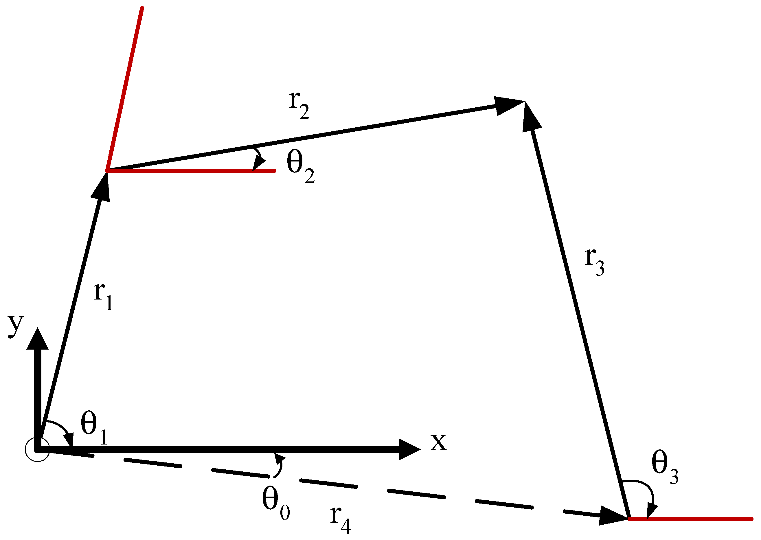
3.2. Four-Bar Linkage Design and Kinematic Analysis
4. Conclusions
Author Contributions
Funding
Institutional Review Board Statement
Informed Consent Statement
Data Availability Statement
Acknowledgments
Conflicts of Interest
References
- Levangie, P.K.; Norkin, C.C. Joint Structure and Function: A Comprehensive Analysis; F.A. Davis: Philadelphia, PA, USA, 2011. [Google Scholar]
- Hamill, J.; Knutzen, K.M. Biomechanical Basis of Human Movement; Lippincott Williams & Wilkins: Philadelphia, PA, USA, 2006. [Google Scholar]
- Muller, M.D. Transfemoral Amputation: Prosthetic Management. Atlas of Amputations and Limb Deficiencies, 4th ed.; American Academy of Orthopaedic Surgeons: Rosemont, IL, USA, 2016; pp. 537–554. [Google Scholar]
- Melfi, M.J.; Evon, S.; McElveen, R. Induction versus permanent magnet motors. IEEE Ind. Appl. Mag. 2009, 15, 28–35. [Google Scholar] [CrossRef]
- Hameyer, K.; Belmans, R.J. Permanent magnet excited brushed DC motors. IEEE Trans. Ind. Electron. 1996, 43, 247–255. [Google Scholar] [CrossRef]
- Derammelaere, S.; Haemers, M.; De Viaene, J.; Verbelen, F.; Stockman, K. A quantitative comparison between BLDC, PMSM, brushed DC and stepping motor technologies. In Proceedings of the 2016 19th International Conference on Electrical Machines and Systems (ICEMS), Chiba, Japan, 13–16 November 2016; pp. 1–5. [Google Scholar]
- Carney, M.E.; Shu, T.; Stolyarov, R.; Duval, J.-F.; Herr, H.M. Design and Preliminary Results of a Reaction Force Series Elastic Actuator for Bionic Knee and Ankle Prostheses. IEEE Trans. Med Robot. Bionics 2021, 3, 542–553. [Google Scholar] [CrossRef]
- Azocar, A.F.; Mooney, L.M.; Duval, J.-F.; Simon, A.M.; Hargrove, L.J.; Rouse, E.J. Design and clinical implementation of an open-source bionic leg. Nat. Biomed. Eng. 2020, 4, 941–953. [Google Scholar] [CrossRef]
- Au, S.K.; Dilworth, P.; Herr, H. An ankle-foot emulation system for the study of human walking biomechanics. In Proceedings of the 2006 IEEE International Conference on 2006, Orlando, FL, USA, 15–19 May 2006; pp. 2939–2945. [Google Scholar]
- Au, S.K.; Herr, H.; Weber, J.; Martinez-Villalpando, E.C. Powered ankle-foot prosthesis for the improvement of amputee ambulation. In Proceedings of the 2007 29th Annual International Conference of the IEEE Engineering in Medicine and Biology Society, Lyon, France, 22–26 August 2007; pp. 3020–3026. [Google Scholar]
- Au, S.K.; Herr, H.M. Powered ankle-foot prosthesis. IEEE Robot. Autom. Mag. 2008, 15, 52–59. [Google Scholar] [CrossRef]
- Eilenberg, M.F.; Geyer, H.; Herr, H. Control of a Powered Ankle–Foot Prosthesis Based on a Neuromuscular Model. IEEE Trans. Neural Syst. Rehabil. Eng. 2010, 18, 164–173. [Google Scholar] [CrossRef] [PubMed]
- Hsieh, T.-H. Design and Control of a Two-Degree-of-Freedom Powered Ankle-Foot Prosthesis. Master’s Thesis, Massachusetts Institute of Technology, Massachusetts Ave, Cambridge, MA, USA, 2019. [Google Scholar]
- Hitt, J.K.; Bellman, R.; Holgate, M.; Sugar, T.G.; Hollander, K.W. The sparky (spring ankle with regenerative kinetics) project: Design and analysis of a robotic transtibial prosthesis with regenerative kinetics. In Proceedings of the International Design Engineering Technical Conferences and Computers and Information in Engineering Conference, Las Vegas, NV, USA, 4–7 September 2007; pp. 1587–1596. [Google Scholar]
- Holgate, M.A.; Hitt, J.K.; Bellman, R.D.; Sugar, T.G.; Hollander, K.W. The SPARKy (Spring Ankle with Regenerative kinetics) project: Choosing a DC mo-tor based actuation method. In Proceedings of the 2008 2nd IEEE RAS & EMBS International Conference on Biomedical Robotics and Biomechatronics, Scottsdale, AZ, USA, 19–22 October 2008; pp. 163–168. [Google Scholar]
- Zhu, J.; Wang, Q.; Wang, L. PANTOE 1: Biomechanical design of powered ankle-foot prosthesis with compliant joints and segmented foot. In Proceedings of the Advanced Intelligent Mechatronics (AIM), 2010 IEEE/ASME International Conference on 2010, Montreal, QC, Canada, 6–9 July 2010; pp. 31–36. [Google Scholar]
- Wang, Q.; Yuan, K.; Zhu, J.; Wang, L. Finite-state control of a robotic transtibial prosthesis with motor-driven nonlinear damping behaviors for level ground walking. In Proceedings of the Advanced Motion Control (AMC), 2014 IEEE 13th International Workshop on 2014, Yokohama, Japan, 14–16 March 2014; pp. 155–160. [Google Scholar]
- Wang, Q.; Yuan, K.; Zhu, J.; Wang, L. Walk the Walk: A Lightweight Active Transtibial Prosthesis. IEEE Robot. Autom. Mag. 2015, 22, 80–89. [Google Scholar] [CrossRef]
- Feng, Y.; Zhu, J.; Wang, Q. Metabolic cost of level-ground walking with a robotic transtibial prosthesis combining push-off power and nonlinear damping behaviors: Preliminary results. In Proceedings of the Engineering in Medicine and Biology Society (EMBC), 2016 IEEE 38th Annual International Conference of the 2016, Orlando, FL, USA, 16–20 August 2016; pp. 5063–5066. [Google Scholar]
- Shultz, A.H.; Mitchell, J.E.; Truex, D.; Lawson, B.E.; Goldfarb, M. Preliminary evaluation of a walking controller for a powered ankle prosthesis. In Proceedings of the Robotics and Automation (ICRA), 2013 IEEE International Conference on 2013, Montreal, QC, Canada, 4 October 2013; pp. 4838–4843. [Google Scholar]
- Shultz, A.H.; Lawson, B.E.; Goldfarb, M. Variable Cadence Walking and Ground Adaptive Standing With a Powered Ankle Prosthesis. IEEE Trans. Neural Syst. Rehabil. Eng. 2015, 24, 495–505. [Google Scholar] [CrossRef]
- Sun, J.; Voglewede, P.A. Controller implementation of a powered transtibial prosthetic device. In Proceedings of the ASME 2011 International Design Engineering Technical Conferences and Computers and Information in Engineering Conference, Washington, DC, USA, 28–31 August 2011; pp. 597–603. [Google Scholar]
- LaPre, A.K.; Umberger, B.R.; Sup, F.C. A Robotic Ankle–Foot Prosthesis With Active Alignment. J. Med. Devices 2016, 10, 025001. [Google Scholar] [CrossRef]
- Cherelle, P.; Matthys, A.; Grosu, V.; Vanderborght, B.; Lefeber, D. The AMP-Foot 2.0: Mimicking intact ankle behavior with a powered transtibial prosthe-sis. In Proceedings of the Biomedical Robotics and Biomechatronics (BioRob), 2012 4th IEEE RAS & EMBS International Conference on 2012, Rome, Italy, 24–27 June 2012; pp. 544–549. [Google Scholar]
- Cherelle, P.; Grosu, V.; Matthys, A.; Vanderborght, B.; Lefeber, D. Design and validation of the ankle mimicking prosthetic (AMP-) foot 2.0. IEEE Trans. Neural Syst. Rehabil. Eng. 2014, 22, 138–148. [Google Scholar] [CrossRef]
- Cherelle, P.; Grosu, V.; Cestari, M.; Vanderborght, B.; Lefeber, D. The AMP-Foot 3, new generation propulsive prosthetic feet with explosive motion char-acteristics: Design and validation. Biomed. Eng. Online 2016, 15, 21. [Google Scholar] [CrossRef] [PubMed]
- Jimenez-Fabian, R.; Flynn, L.; Geeroms, J.; Vitiello, N.; VanderBorght, B.; Lefeber, D. Sliding-Bar MACCEPA for a Powered Ankle Prosthesis. J. Mech. Robot. 2015, 7, 041011. [Google Scholar] [CrossRef]
- Jimenez-Fabian, R.; Geeroms, J.; Flynn, L.; Vanderborght, B.; Lefeber, D. Reduction of the torque requirements of an active ankle prosthesis using a parallel spring. Robot. Auton. Syst. 2017, 92, 187–196. [Google Scholar] [CrossRef]
- Gao, F.; Liu, Y.; Liao, W.-H. A new powered ankle-foot prosthesis with compact parallel spring mechanism. In Proceedings of the Robotics and Biomimetics (ROBIO), 2016 IEEE International Conference on 2016, Liege, Belgium, 13–14 December 2016; pp. 473–478. [Google Scholar]
- Gao, F.; Liu, Y.; Liao, W.-H. Implementation and Testing of Ankle-Foot Prosthesis With a New Compensated Controller. IEEE/ASME Trans. Mechatron. 2019, 24, 1775–1784. [Google Scholar] [CrossRef]
- Grimmer, M.; Holgate, M.; Holgate, R.; Boehler, A.; Ward, J.; Hollander, K.; Sugar, T.; Seyfarth, A. A powered prosthetic ankle joint for walking and run-ning. Biomed. Eng. Online 2016, 15, 37–52. [Google Scholar] [CrossRef]
- Alleva, S.; Antonelli, M.G.; Zobel, P.B.; Durante, F. Biomechanical Design and Prototyping of a Powered Ankle-Foot Prosthesis. Materials 2020, 13, 5806. [Google Scholar] [CrossRef]
- Dong, D.; Ge, W.; Convens, B.; Sun, Y.; Verstraten, T.; Vanderborght, B. Design, Optimization and Energetic Evaluation of an Efficient Fully Powered An-kle-Foot Prosthesis With a Series Elastic Actuator. IEEE Access 2020, 8, 61491–61503. [Google Scholar] [CrossRef]
- She, H.; Zhu, J.; Tian, Y.; Wang, Y.; Huang, Q. Design of a powered ankle-foot prosthesis with an adjustable stiffness toe joint. Adv. Robot. 2020, 34, 689–697. [Google Scholar] [CrossRef]
- Sup, F.; Varol, H.A.; Mitchell, J.; Withrow, T.J.; Goldfarb, M. Preliminary Evaluations of a Self-Contained Anthropomorphic Transfemoral Prosthesis. IEEE/ASME Trans. Mechatron. 2009, 14, 667–676. [Google Scholar] [CrossRef]
- Martinez-Villalpando, E.C.; Herr, H. Agonist-antagonist active knee prosthesis: A preliminary study in level-ground walking. J. Rehabil. Res. Dev. 2009, 46, 46. [Google Scholar] [CrossRef]
- Rouse, E.J.; Mooney, L.M.; Martinez-Villalpando, E.C.; Herr, H.M. Clutchable series-elastic actuator: Design of a robotic knee prosthesis for minimum energy consumption. In Proceedings of the 2013 IEEE 13th International Conference on Rehabilitation Robotics (ICORR), Beijing, China, 15–18 July 2013; pp. 1–6. [Google Scholar]
- Shultz, A.H.; Lawson, B.E.; Goldfarb, M. Running with a powered knee and ankle prosthesis. IEEE Trans. Neural Syst. Rehabil. Eng. 2014, 23, 403–412. [Google Scholar] [CrossRef] [PubMed]
- Rouse, E.J.; Mooney, L.M.; Herr, H.M. Clutchable series-elastic actuator: Implications for prosthetic knee design. Int. J. Robot. Res. 2014, 33, 1611–1625. [Google Scholar] [CrossRef]
- Zhao, H.; Reher, J.; Horn, J.; Paredes, V.; Ames, A.D. Realization of nonlinear real-time optimization based controllers on self-contained transfemoral prosthesis. In Proceedings of the ACM/IEEE Sixth International Conference on Cyber-Physical Systems, Seattle, DC, USA, 14–16 April 2015; pp. 130–138. [Google Scholar]
- Zhao, H.; Ambrose, E.; Ames, A.D. Preliminary results on energy efficient 3D prosthetic walking with a powered compliant transfemoral prosthesis. In Proceedings of the 2017 IEEE International Conference on Robotics and Automation (ICRA), Brussels, Belgium, 11–12 December 2017; pp. 1140–1147. [Google Scholar]
- Elery, T.; Rezazadeh, S.; Nesler, C.; Gregg, R.D. Design and validation of a powered knee–ankle prosthesis with high-torque, low-impedance actuators. IEEE Trans. Robot. 2020, 36, 1649–1668. [Google Scholar] [CrossRef] [PubMed]
- Flynn, L.; Geeroms, J.; Jimenez-Fabian, R.; Heins, S.; Vanderborght, B.; Munih, M.; Molino Lova, R.; Vitiello, N.; Lefeber, D. The challenges and achieve-ments of experimental implementation of an active transfemoral prosthesis based on biological quasi-stiffness: The CYBERLEGs beta-prosthesis. Front. Neurorobotics 2018, 12, 80. [Google Scholar] [CrossRef]
- Hong, W.; Paredes, V.; Chao, K.; Patrick, S.; Hur, P. Consolidated control framework to control a powered transfemoral prosthesis over inclined terrain conditions. In Proceedings of the 2019 International Conference on Robotics and Automation (ICRA), Montreal, QC, Canada, 20–24 May 2019; pp. 2838–2844. [Google Scholar]
- Lenzi, T.; Cempini, M.; Hargrove, L.; Kuiken, T. Design, development, and testing of a lightweight hybrid robotic knee prosthesis. Int. J. Robot. Res. 2018, 37, 953–976. [Google Scholar] [CrossRef]
- Liu, J.; Osman, N.A.A.; Kouzbary, M.A.; Kouzbary, H.A.; Razak, N.A.A.; Shasmin, H.N.; Arifin, N. Optimization and comparison of typical elastic actuators in powered ankle-foot prosthesis. Int. J. Control. Autom. Syst. 2022, 20, 232–242. [Google Scholar] [CrossRef]
- Hedrick, E.A.; Malcolm, P.; Wilken, J.M.; Takahashi, K.Z. The effects of ankle stiffness on mechanics and energetics of walking with added loads: A pros-thetic emulator study. J. Neuroeng. Rehabil. 2019, 16, 1–15. [Google Scholar] [CrossRef]
- Clites, T.R.; Shepherd, M.K.; Ingraham, K.A.; Wontorcik, L.; Rouse, E.J. Understanding patient preference in prosthetic ankle stiffness. J. Neuroeng. Rehabil. 2021, 18, 1–16. [Google Scholar] [CrossRef]
- Quesada, R.E.; Caputo, J.M.; Collins, S.H. Increasing ankle push-off work with a powered prosthesis does not necessarily reduce metabolic rate for tran-stibial amputees. J. Biomech. 2016, 49, 3452–3459. [Google Scholar] [CrossRef]
- Burgess, S.C. A review of linkage mechanisms in animal joints and related bio-inspired designs. Bioinspiration Biomim 2021, 16, 041001. [Google Scholar] [CrossRef]
- Kim, S.I.; Kim, Y.Y. Topology optimization of planar linkage mechanisms. Int. J. Numer. Methods Eng. 2014, 98, 265–286. [Google Scholar] [CrossRef]
- Sup, F.; Bohara, A.; Goldfarb, M. Design and Control of a Powered Transfemoral Prosthesis. Int. J. Robot. Res. 2008, 27, 263–273. [Google Scholar] [CrossRef] [PubMed]
- Sun, J.; Voglewede, P.A. Powered transtibial prosthetic device control system design, implementation, and bench testing. J. Med. Devices 2014, 8, 011004. [Google Scholar] [CrossRef]
- Sun, J.; Fritz, J.M.; Del Toro, D.R.; Voglewede, P.A. Amputee Subject Testing Protocol, Results, and Analysis of a Powered Transtibial Prosthetic Device. J. Med Devices 2014, 8, 041007–410076. [Google Scholar] [CrossRef] [PubMed]
- Zhao, H.; Reher, J.; Horn, J.; Paredes, V.; Ames, A.D. Realization of stair ascent and motion transitions on prostheses utilizing optimization-based control and intent recognition. In Proceedings of 2015 IEEE International Conference on Rehabilitation Robotics (ICORR), Singapore, 11–14 August 2015; pp. 265–270. [Google Scholar]
- Au, S.K.; Weber, J.; Herr, H. Biomechanical design of a powered ankle-foot prosthesis. In Proceedings of the 2007 IEEE 10th International Conference on Rehabilitation robotics, Noordwijk, The Netherlands, 13–15 June 2007; pp. 298–303. [Google Scholar]
- Ficanha, E.M.; Rastgaar, M.; Kaufman, K.R. A two-axis cable-driven ankle-foot mechanism. Robot. Biomim. 2014, 1, 379. [Google Scholar] [CrossRef]
- Caputo, J.M.; Collins, S.H. An experimental robotic testbed for accelerated development of ankle prostheses. In Proceedings of the 2013 IEEE International Conference on Robotics and Automation, Karlsruhe, Germany, 6–10 May 2013; pp. 2645–2650. [Google Scholar]
- Caputo, J.M.; Collins, S.H. A Universal Ankle–Foot Prosthesis Emulator for Human Locomotion Experiments. J. Biomech. Eng. 2014, 136, 035002. [Google Scholar] [CrossRef]
- Pham, A.-D.; Ahn, H.-J. Rigid precision reducers for machining industrial robots. Int. J. Precis. Eng. Manuf. 2021, 22, 1469–1486. [Google Scholar] [CrossRef]
- Lara-Barrios, C.M.; Blanco-Ortega, A.; Guzmán-Valdivia, C.H.; Valles, K.D.B. Literature review and current trends on transfemoral powered prosthetics. Adv. Robot. 2017, 32, 51–62. [Google Scholar] [CrossRef]
- Sensinger, J.W. Efficiency of high-sensitivity gear trains, such as cycloid drives. J. Mech. Des. 2013, 135, 071006. [Google Scholar] [CrossRef]
- Blagojevic, M.; Kocic, M.; Marjanovic, N.; Stojanovic, B.; Dordevic, Z.; Ivanovic, L.; Marjanovic, V. Influence of the friction on the cycloidal speed reducer efficiency. J. Balk. Tribol. Assoc. 2012, 18, 217–227. [Google Scholar]
- Lee, K.; Hong, S.; Oh, J.-H. Development of a Lightweight and High-efficiency Compact Cycloidal Reducer for Legged Robots. Int. J. Precis. Eng. Manuf. 2019, 21, 415–425. [Google Scholar] [CrossRef]
- Sensinger, J.W.; Lipsey, J.H. Cycloid vs. harmonic drives for use in high ratio, single stage robotic transmissions. In Proceedings of the 2012 IEEE International Conference on Robotics and Automation, St Paul, MN, USA, 14–18 May 2012; pp. 4130–4135. [Google Scholar]
- Qiu, Z.; Xue, J. Review of Performance Testing of High Precision Reducers for Industrial Robots. Measurement 2021, 183, 109794. [Google Scholar] [CrossRef]
- Botsiber, D.; Kingston, L. Design and performance of the cycloid speed reducer. Mach. Des. 1956, 28, 65–69. [Google Scholar]
- Malhotra, S.; Parameswaran, M. Analysis of a cycloid speed reducer. Mech. Mach. Theory 1983, 18, 491–499. [Google Scholar] [CrossRef]
- Hsieh, C.-F. Study on Geometry Design of Rotors Using Trochoidal Curve. Ph.D. Dissertation, Department of Mechanical Engineering, National Chung Cheng University, Chiayi, Taiwan, 2006. [Google Scholar]
- Robison, A.J.; Vacca, A. Performance comparison of epitrochoidal, hypotrochoidal, and cycloidal gerotor gear profiles. Mech. Mach. Theory 2021, 158, 104228. [Google Scholar] [CrossRef]
- Kennedy, J.; Eberhart, R. Particle swarm optimization. In Proceedings of the ICNN′95-International Conference on Neural Networks, Perth, WA, Australia, 27 November–1 December 1995; pp. 1942–1948. [Google Scholar]
- Sengupta, S.; Basak, S.; Peters, R.A. Particle Swarm Optimization: A Survey of Historical and Recent Developments with Hybridization Perspectives. Mach. Learn. Knowl. Extr. 2018, 1, 157–191. [Google Scholar] [CrossRef]
- Robinson, J.; Sinton, S.; Rahmat-Samii, Y. Particle swarm, genetic algorithm, and their hybrids: Optimization of a profiled corrugated horn antenna. In Proceedings of the IEEE Antennas and Propagation Society International Symposium (IEEE Cat. No. 02CH37313), San Antonio, TX, USA, 16–21 June 2002; pp. 314–317. [Google Scholar]
- Abdel-Kader, R.F. Genetically improved PSO algorithm for efficient data clustering. In Proceedings of the 2010 Second International Conference on Machine Learning and Computing, Bangalore, India, 9–11 February 2010; pp. 71–75. [Google Scholar]
- Das, S.; Abraham, A.; Konar, A. Particle Swarm Optimization and Differential Evolution Algorithms: Technical Analysis, Applications and Hybridization Perspectives. In Advances of Computational Intelligence in Industrial Systems; Springer: Berlin/Heidelberg, Germany, 2008; Volume 116. [Google Scholar]
- Wang, D.; Tan, D.; Liu, L. Particle swarm optimization algorithm: An overview. Soft Comput. 2018, 22, 387–408. [Google Scholar] [CrossRef]
- Sardashti, A.; Daniali, H.M.; Varedi, S.M. Optimal free-defect synthesis of four-bar linkage with joint clearance using PSO algorithm. Meccanica 2013, 48, 1681–1693. [Google Scholar] [CrossRef]
- Sun, Y.; Ge, W.; Zheng, J.; Dong, D. Design and Evaluation of a Prosthetic Knee Joint Using the Geared Five-Bar Mechanism. IEEE Trans. Neural Syst. Rehabil. Eng. 2015, 23, 1031–1038. [Google Scholar] [CrossRef]
- Steele, A.G.; Hunt, A.; Etoundi, A.C. Development of a bio-inspired knee joint mechanism for a bipedal robot. In Proceedings of the Conference on Biomimetic and Biohybrid Systems, Stanford, CA, USA, 26–28 July 2017; pp. 418–427. [Google Scholar]
- Jin, D.; Zhang, R.; O Dimo, H.; Wang, R.; Zhang, J. Kinematic and dynamic performance of prosthetic knee joint using six-bar mechanism. J. Rehabil. Res. Dev. 2003, 40, 39. [Google Scholar] [CrossRef] [PubMed]
- Radcliffe, C. Four-bar linkage prosthetic knee mechanisms: Kinematics, alignment and prescription criteria. Prosthet. Orthot. Int. 1994, 18, 159–173. [Google Scholar] [CrossRef]
- Patek, S.N.; Nowroozi, B.; Baio, J.; Caldwell, R.L.; Summers, A.P. Linkage mechanics and power amplification of the mantis shrimp’s strike. J. Exp. Biol. 2007, 210, 3677–3688. [Google Scholar] [CrossRef] [PubMed] [Green Version]
- Lin, C.-C.; Chang, W.-T. The force transmissivity index of planar linkage mechanisms. Mech. Mach. Theory 2002, 37, 1465–1485. [Google Scholar] [CrossRef]
- Braren, R. Cycloidal Gears. US Patent US4050331A, 27 September 1977. [Google Scholar]
- Heyer, J.H. Design of Silent, Miniature, High Torque Actuators; Massachusetts Institute of Technology: Cambridge, MA, USA, 1999. [Google Scholar]
- Lin, W.-S.; Shih, Y.-P.; Lee, J.-J. Design of a two-stage cycloidal gear reducer with tooth modifications. Mech. Mach. Theory 2014, 79, 184–197. [Google Scholar] [CrossRef]
- Rothenhofer, G.; Walsh, C.; Slocum, A. Transmission ratio based analysis and robust design of mechanisms. Precis. Eng. 2010, 34, 790–797. [Google Scholar] [CrossRef]
- Liu, J.; Abu Osman, N.A.; Al Kouzbary, M.; Al Kouzbary, H.; Razak, N.A.A.; Shasmin, H.N.; Arifin, N. Stiffness estimation of planar spiral spring based on Gaussian process regression. Sci. Rep. 2022, 12, 1–15. [Google Scholar] [CrossRef] [PubMed]


| Motor | Motor’s Power (Watt) | Elastic Element(s) | Stiffness | |
|---|---|---|---|---|
| DC motor | 150 | Series spring | Flexion 300 kN/m Extension 600 kN/m | [9] |
| DC motor | 150 | Series and parallel springs | 1200 kN/m (series) 770 kN/m (parallel) | [10] |
| BLDC motor | 200 | Series and parallel springs | 600 kN/m (series) 630 Nm/rad (parallel) | [11] |
| BLDC motor | 200 | Series and parallel springs | 1200 Nm/rad (series) 533 Nm/rad (parallel) | [12] |
| BLDC motor 1 | 400 | N/A | - | [13] |
| BLDC motor 1 | 600 | Series spring | 378 kN/m | [7] |
| DC motor | 150 | Series and Nonlinear keel springs | 32 kN/m (series) | [14] |
| DC motor | 150 | Series spring | 50 kN/m (series) | [15] |
| DC motor | 83 | Series springs | 500 kN/m (series) 200 kN/m (toe-spring) | [16] |
| BLDC motor | 50 | N/A | - | [17] |
| DC motor | 150 | N/A | - | [18,19] |
| BLDC motor | 200 | Parallel spring | 43 Nm/rad | [20] |
| BLDC motor | 200 | Parallel spring | 240 Nm/rad | [21] |
| DC motor | 150 | Series spring | 26.6 Nm/rad | [22] |
| BLDC motor | 200 | N/A | - | [23] |
| DC motor | 60 | Series springs | 120 kN/m (series) 300 kN/m (toe-spring) | [24] |
| DC motor | 60 | Series springs | 60 kN/m (series) 300 kN/m (toe-spring) | [25] |
| BLDC motor | 50 | Series springs | 180 kN/m(series) 300 kN/m (toe-spring) | [26] |
| DC motor | 60 | Series spring | 132 kN/m | [27] |
| DC motor | 60 | Series and parallel springs | 130 kN/m (series) 270 Nm/rad (parallel) | [28] |
| DC motor | 90 | Nonlinear parallel spring | No information given | [29,30] |
| BLDC motor | 200 | Series spring | 445 kN/m | [31] |
| BLDC motor | 283 | Shock-absorber | No information given | [32] |
| DC motor | 150 | Series spring | 208 kN/m | [33] |
| DC motor | 150 | Series springs | 210 kN/m 42 Nm/rad (toe) | [34] |
| Motor | Motor’s Power (Watt) | Elastic Element(s) | Stiffness | |
|---|---|---|---|---|
| BLDC motor | 200 | Series spring for ankle actuator | 38 kN/m | [35] |
| DC motor | 150 (extension) 60 (flexion) | Series springs | 160 Nm/rad 137 Nm/rad | [36] |
| DC motor | 150 | Series spring | 200 Nm/rad | [37] |
| BLDC motor | 200 | No information | - | [38] |
| BLDC motor | 200 | Series springs | 385 kN/m (extension) 338 kN/m (flexion) | [39] |
| BLDC motor | 600 | Series spring | 378 kN/m | [7] |
| BLDC motor | 483 | N/A | - | [40] |
| BLDC motor | 206 | Torsion series springs | 1146 Nm/rad | [41] |
| BLDC motor | 400 | Torsion series springs | 600 Nm/rad | [8] |
| BLDC motor | 410 | - | - | [42] |
| BLDC motor | 40 | Series springs | 17–974 Nm/rad | [43] |
| BLDC motor | 240 | - | - | [44] |
| BLDC motor | 90 | Shock absorber | No information given | [45] |
| Common Mechanism | Advantages | Drawbacks | |
|---|---|---|---|
| slider-crank |
|
| [12,16,18,31,35] |
| four-bar linkage |
| [8,13,54,55,56] | |
| direct drive |
|
| [21,38,41,57] [8] [42] |
| cable-driven |
|
| [56,57,58,59,60,61] |
| Description | Value | |
|---|---|---|
| d | circle diameter of base circle | 50.4 mm |
| D | reference circle diameter of the fixed ring pins | 54.6 mm |
| N | number of pins | 13 |
| n | number of lobes | 12 |
| e | eccentricity | 4 mm |
| i | reduction ratio | |
| e | roller radius | 3.175 mm |
| dh | hole diameter | = 14.35 mm |
| Link | Parameters |
|---|---|
| r1 | 30 mm |
| r2 | 56.624 mm |
| r3 | 66 mm |
| rb | 66.193 mm |
| q0 | 0.43706 rad |
Publisher’s Note: MDPI stays neutral with regard to jurisdictional claims in published maps and institutional affiliations. |
© 2022 by the authors. Licensee MDPI, Basel, Switzerland. This article is an open access article distributed under the terms and conditions of the Creative Commons Attribution (CC BY) license (https://creativecommons.org/licenses/by/4.0/).
Share and Cite
Al Kouzbary, M.; Al Kouzbary, H.; Liu, J.; Khamis, T.; Al-Hashimi, Z.; Shasmin, H.N.; Arifin, N.; Abu Osman, N.A. Robotic Knee Prosthesis with Cycloidal Gear and Four-Bar Mechanism Optimized Using Particle Swarm Algorithm. Actuators 2022, 11, 253. https://doi.org/10.3390/act11090253
Al Kouzbary M, Al Kouzbary H, Liu J, Khamis T, Al-Hashimi Z, Shasmin HN, Arifin N, Abu Osman NA. Robotic Knee Prosthesis with Cycloidal Gear and Four-Bar Mechanism Optimized Using Particle Swarm Algorithm. Actuators. 2022; 11(9):253. https://doi.org/10.3390/act11090253
Chicago/Turabian StyleAl Kouzbary, Mouaz, Hamza Al Kouzbary, Jingjing Liu, Taha Khamis, Zaina Al-Hashimi, Hanie Nadia Shasmin, Nooranida Arifin, and Noor Azuan Abu Osman. 2022. "Robotic Knee Prosthesis with Cycloidal Gear and Four-Bar Mechanism Optimized Using Particle Swarm Algorithm" Actuators 11, no. 9: 253. https://doi.org/10.3390/act11090253