Analysis of the Possibilities of Using a Driver’s Brain Activity to Pneumatically Actuate a Secondary Foot Brake Pedal


Department of Manufacturing Engineering and Metrology, Faculty of Mechatronics and Mechanical Engineering, Kielce University of Technology, aleja Tysiaclecia Panstwa Polskiego 7, 25-314 Kielce, Poland
*
Author to whom correspondence should be addressed.
Actuators 2020, 9(3), 49; https://doi.org/10.3390/act9030049
Submission received: 9 June 2020
/
Revised: 23 June 2020
/
Accepted: 29 June 2020
/
Published: 1 July 2020
(This article belongs to the Special Issue Variable Stiffness Actuators)
Abstract
:The study deals with the use of the driver’s brain activity for wireless remote control of the pneumatic actuator exerting pressure on the secondary foot brake pedal. The conducted experimental tests confirm that bioelectrical signals (BES) induced by muscle tension within the head can be used for wireless remote control of a pneumatic actuator to exert a pressure force on a foot brake pedal for disabled drivers during car emergency braking. It has been shown that the BES artefacts generated by muscular tension inside the head (e.g., movement of the face and eyelids, clenching of jaws, and pressing the tongue on the palate) are the easiest to control of the pneumatic systems. The proposed car braking assistance system controlled by the driver’s brain activity can improve the driving safety of disabled people, e.g., by reducing the reaction time of pneumatically assisted emergency braking.
1. Introduction
Currently, car vehicle manufacturers are striving to implement autonomous driving vehicle (ADV) technology. With the advancement of innovative technology, new cases of ADV use will appear in means of transport, which largely depend on the type of vehicle and the place of their driving. The final ADV plan is a driverless car. However, autonomous vehicles do not correctly recognise various human intentions. Recently, attention has been paid to the brain-computer interface (BCI) cooperation strategy and automatic driving [1]. The human brain provides a wealth of information about a driver’s cognitive and emotional states [2]. The purpose of various studies is to use the brain (mind) in vehicle control systems or their particular mechanisms. Particular solutions, such as a brain-controlled car for people with disabilities, are also being considered. Reference [3] presented a car for a disabled person, which reads brain signals and controls the car accordingly. Brain-controlled vehicles based on the driver-vehicle interface (DVI) can provide mobility for disabled people [4]. In Reference [5], a new controller assistant design using predictive control methods to improve the performance and safety of the car controlled by the driver’s brain was proposed. In References [6,7,8], the development of brain-controlled cars that can be used by people with disabilities was presented. Various brain states as patterns of neural interaction to control the car are analysed [9]. The mental state of the driver is characterized by different brain frequencies, e.g., beta waves from 12 to 30 Hz are a state of concentration, and alpha waves from 8 to 12 Hz are a state of relaxation [10]. Additionally, muscle contractions within the head are a unique pattern of bioelectric signals whose separation can be used to control the car. There are also press reports that Chinese engineers from Nankai University in Tianjin have developed a brain-controlled car. In Reference [11], a study on the use of the operator’s bioelectric signals to control electro-pneumatic positioning systems has been presented. The operator was equipped with a brain-computer interface (BCI), which measures and analyses bioelectric signals (BESs) and then converts them into appropriate control signals for the pneumatic system. This solution was used to safely control pneumatic actuators. The emergency stopping of a pneumatic actuator using ”thoughts“ was analysed. Reference [12] presents a new design of a wearable orthosis of the elbow joint with a bi-muscular pneumatic servo-drive with control based on the recording of bioelectric signals.
The initial studies presented in the work are part of extensive research in which the main purpose is to adapt disabled people to self-driving. One of the research threads is to determine the reaction time of drivers of the car during emergency braking. The study will take into account various scenarios, such as car speed, distance from the obstacle, age of the driver, degree and type of disability of the driver, various driver tasks, and changing traffic situations. It is planned to carry out tests both on the driving simulator and on the Kielce Track. The driving simulator is equipped with a driver’s cab with sensors on the position of the vehicle controls including the accelerator, brake, and clutch pedals as well as a gear lever. The reaction time during emergency braking depends on three factors: driver’s mental reaction time, brake reaction time, and motor car reaction time. In the case of a driver who is distracted and tired, has temporary attentional lapses, mental stress, neurological and motor diseases, or takes medication, his reaction time during braking is significantly slowed down. There are known works regarding the detection of driver brain activity for simulated driving, but there are no works regarding the use of driver brain activity for emergency braking in real road conditions. These tests are of particular importance for drivers with disabilities. Many people have motor disabilities due to amputation or neurological diseases.
In this work, we have developed an innovative system for using the brain activity of the disabled driver to control a pneumatic actuator by exerting pressure on the secondary foot brake pedal during emergency braking. The authors proposed a new BCI, which uses a neural impulse actuator (NIA), wireless network interface controller (WNIC), and controller of a pneumatic actuator (PA). The captured BESs were analysed by fast Fourier transforms (FFT), which were translated into commands for control of a pneumatic valve that starts the pneumatic actuator. During an emergency, the driver must concentrate on braking, which induces his brain. The presented pneumatic actuator assembly is adopted to apply the required pressure to an automobile brake pedal, but it can also be used as a removable brake pedal actuator adaptable to accurate and rapid testing procedures, such as those required in the assembly line testing of vehicles. For safe driving, the car should be equipped with obstacle detection and avoidance mechanisms. If the developed braking assistance system becomes cost-effective, it will be possible to enable more functions. In the future, brain support for driving systems, such as automatic navigation systems, automatic speed control mechanisms, traffic signals, signboard detection, and automatic car starting mechanisms, will be analysed.
2. Model of Actuating the Secondary Foot Brake Pedal
Dual control systems are installed in cars to ensure driving safety in special conditions. The dual control systems in the car relate to auxiliary devices, such as clutch pedals, brake pedals, and acceleration pedals, which are located on the passenger side. Such dual control is mainly installed in driving schools, but it would also be useful for people who require to be checked while driving. Dual brake pedals themselves have been introduced to increase the safety standard and driving comfort for certified driver rehabilitation specialists (CDRS) who supervise disabled drivers. The dual brake pedals can also be used by people who want to extend the training period in a family vehicle. In this case, the dual brake pedals are ideal for long-term use beyond the training evaluation period by reducing risk and stress for both the driver and the passenger. A disabled driver during independent driving can react to road hazards with some delay, especially during emergency braking. Therefore, the authors proposed a brain-controlled pneumatic system, which consists of the fact that, as a result of the driver’s brain activity, the pneumatic actuator presses on the secondary foot brake pedal. A new solution of the dual foot brake pedals, consisting of the primary driver pedal and the secondary pedal pressed by the pneumatic actuator, is shown in Figure 1.
The primary foot brake pedal is rigidly connected to the secondary pedal by a tubular shaft. The driver presses his foot on the brake pedal while braking the vehicle. A spring returns the pedals to the upper (resting) position when the driver’s foot is removed from the pedal. The secondary foot brake pedal is pressed by a pneumatic cylinder, which is controlled by the driver as a result of his brain activity during emergency braking. When relaxing, the pneumatic actuator releases the pressure on the secondary brake pedal. The dual braking system ensures greater driving safety because the secondary brake pedal is pneumatically pressed when the disabled driver cannot press the primary brake pedal in time. The design solution of a pneumatic actuator assembly with mounting accessories is shown in Figure 2.
The pneumatic actuator used in the pneumatic assembly is a single-acting cylinder with a single-piston rod. In a single-acting actuator, compressed air is supplied only to one side of the piston surface. The other side is open to the atmosphere. The single-acting cylinder uses compressed air only for the working stroke with movement in one direction. A built-in spring affected the return movement of the piston. The presented pneumatic actuator assembly is adapted to exert a specific pressure force on the secondary foot brake pedal in a car. When selecting the stroke of the pneumatic cylinder, it was assumed that the brake pedal sits 160 mm from the floor, when this distance is measured perpendicularly to the front face of the pedal. As the brake pedal is pressed by the contact pad of the pneumatic actuator, it rotates through an arc. This angle can be up to 40°, depending on the vehicle type. The total brake pedal deflection is 80 mm. The free displacement of the brake pedal, which may be around 6% of the available deflection, must be taken into account.
Based on data from literature, the pressure force and the reaction time of an abled driver during emergency braking were analysed [13]. Manning [14] registered a mean peak force of 750 N while braking and found no statistical difference between men and women. According to Reference [15], the average brake force in an emergency braking event was 796 N, and the reaction time was 0.5 s. In an emergency braking event, the simulated average speed was 67 km/h. Furthermore, it is shown that, during emergency events, the brake pedal is used more often than the clutch. It was also clearly stated that subjects who placed their foot higher up on the brake pedal produced a higher maximum brake force. People over the age of 50 produced maximum emergency braking force much more slowly than younger people. The paper [16] presents the results of research on drivers’ reaction time in the case of accident risk. These studies have been conducted on a driving simulator. The purpose of the test was also to determine braking force depending on the initial lower extremity posture on the brake pedal. Figure 3 compares the pressure force on the secondary foot brake pedal exerted by the pneumatic actuator and the pressure force exerted by the driver’s feet at full pedal deflection during emergency braking.
The pressure force of the pneumatic actuator is constant throughout its stroke range. However, the brake pedal pressure felt by the driver’s foot gradually increases. In addition, it will be significantly felt by the driver when the brake pedal reaches a height of 50% of the available deflection. When the brake pedal deflection exceeds 60% of the available deflection, braking becomes effective.
3. Control System Solution
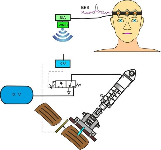
The control system solution of the test bench for testing a pneumatically actuated secondary foot brake pedal based on the driver’s brain activity is shown in Figure 4. The NIA as a recording device reads and analyses BESs induced by the driver’s brain activity. The neural impulse actuator then decodes them into control signals sent by a WNIC to the controller of a pneumatic actuator. The pneumatic actuator is supplied from a compressed air reservoir. The size of the air reservoir depends on the air consumption of the pneumatic actuator.
The NIA is a non-invasive device used as a brain-machine interface (BMI) that reads BESs caused by brain activity, muscle tension in the head, and during eye movement [17]. NIA offers the interpretation of raw EEG (electroencephalography) and EMG (electromyography) data as well as their translation into an understandable frequency spectrum. EEG records a series of brain waves, and EMG records muscle movement. NIA is composed of a control box, client software, and a headband with three diamond-shaped sensors, which is put on the driver’s forehead. In the control box, recorded BES are analyzed, translated, and sent to the NIA client software suite for further processing. Client software relays the binary impulse signals sent from the control box and passes them onto an executable program based upon command specifications. The software provided with NIA enables calibration and defining control profiles creating applications. The rubber headband consists of three diamond-shaped conductor plates with BESs sensors based on carbon nanofibers (CNFs), which are bound to the forehead as shown in Figure 5.
CNFs is a new carbon nanomaterial that has unique chemical and physical properties that are exceptionally suitable for electrodes for reading bio-signals [18]. Sensors based on carbon nanofibers are about 100 times more sensitive than traditional sensors. These sensors allow the capture of bio-signals, which were completely masked in previous measurements. This makes it necessary to separate the signals into individual components, which is done using fairly complex mathematical operations, including Fast Fourier Transformation. The advantage of NIA is that it can be easily worn and removed when needed. The NIA device does not limit the physical movement of the driver and allows you to experiment with various mental states that the driver experiences.
Effective control of a pneumatic actuator with the use of NIA requires a snug fit of the sensors to readers of BESs, calibration of the device, and training of the test participants (drivers). To test the use of bio-signals and wireless communication in the control of a pneumatically actuated foot brake pedal, a WNIC was built. The WNIC enables the streaming of high-fidelity control signals to a device connected to Wi-Fi in real-time. Wireless communication does not distort the control signals and is not limited by wires that cause noise and interference. The controller of a pneumatic actuator (PA) enables control of the movement of the brake pedal actuator by an electrical input signal connected to a directional 3/2-way solenoid pilot-operated valve. To extend the actuator piston rod (emergency braking condition), the monostable 3/2 normally closed (NC) valve must be activated by an electric signal. To retract the actuator piston rod (brake release state), the electric signal in the valve disappears. The controller of a pneumatic actuator retrieves a feedback signal from the position transducer of the secondary brake pedal. The measuring system is designed to check the position of the brake foot pedal and protect against uncontrolled movement of the pneumatic actuator. Once the BESs are captured by the NIA, they are analysed and separated through FFT into different frequencies to be translated into commands that the user defines as an electric control signal to the valve, which starts the pneumatic actuator pressing the secondary foot brake pedal. To obtain the extension of the actuator piston rod (pressure on the brake pedal) and retract the actuator piston rod (release pedal pressure), control commands u = (down, up) were selected.
The experimental conditions for a bio-signal measurement result from the technical capabilities of the NIA. The recorded biological signals require the use of signal processing algorithms to remove noise by accurately quantifying the signal model and its components. Figure 6 shows the recorded time-dependent BES spectrum activated by muscle tension in the head. However, Figure 7 shows the recorded BES frequency spectrum activated by muscle tension in the head. As you can see in Figure 6, the BES electrical potentials have both positive and negative voltage.
Analysis of the recorded frequency spectrum shows that it is possible to distinguish between mental tasks for a selected frequency band. The usable BESs spectrum band is in the frequency range from 0.5 Hz to 50 Hz. Due to the symmetry of the spectral band, it is enough to include only half of it wide. There are essentially two main problems when detecting, recording, and decoding bio-signals. The first problem is measurement noise, and the second problem is an undesirable electrical potential (electromagnetic interference). Therefore, the recorded BES frequency spectrum requires pre-processing to eliminate noise or other possible interference. The pre-processing of the BESs frequency spectrum usually includes signal filtering [19]. Digital filters, spatial filters, and signal whitening methods are usually used at this stage. The frequency spectrum of BESs is analysed by a discrete Fourier transform (DFT) and power spectral density (PSD). DFT is given by Equation [20].
where ω is the frequency, x is the measured BESs, and n is the number of the signal sample.
In general, it is not possible to calculate a DFT of a signal because it would require an infinite number of operations. A finite number of discrete-time Fourier transform (DTFT) frequency samples can always be calculated if the sample spacing is small enough to ensure a good spectrum representation. If x(n) is limited with the duration of N samples, then Equation (1) is written as follows [21].
where ωk is the discrete frequency of DTFT (ωk = 2πk/N) and k is the bin.
The short-time Fourier transform (STFT) can represent sequences of any length by breaking them into blocks or frames and applying the DTFT for each of them. For N samples, the frame length M < N is considered. Then the frame’s Fourier transform for multiply xi(n) with the window w(n) is shown below.
where K is the number of overlapping frames of length M.
The spectral density obtained from Equation (4) is shown below.
The power spectrum according to the second modification made by Welch to Bartlett’s method is shown below [22].
where U is the normalisation factor for the power spectrum in the window function w(n).
Based on Equation (6), the main power spectrum in a frequency band for a limited time can be calculated by the equation below.
To translate BES data into a command signal, all negative electrical potential values must be converted to positive values. This action aims to present the BES spectrum in the time series by enabling the definition of standard parameters such as mean, peak, and field values. Based on this spectrum, the process of preparing a command signal for a pneumatically controlled system is carried out. Peaks with excessive value are trimmed, and the discrete signal is transformed into a continuous function. Additionally, a digital smoothing algorithm was used, which determine the main direction of signal travel. For smoothing BESs data, an FFT filter, a low-pass filter (LF), and Lowess method (LM) was used. The effect of the BES data smoothing process is shown in Figure 8.
LM also is known as locally weighted polynomial regression (LWPR). LWPR approximates nonlinear functions in large-dimension spaces with redundant and insignificant inputs. For testing brain activity to control the pneumatic system, the BESs frequency spectrum based on the LF and the LM at a cut-off of 50 Hz was used. As a result of the test, the BES spectrum was determined to provide the best results in generating command signals for the pneumatic system. It was found that pressing the tongue to the palate or clamping the jaw with more or less force stimulates brain activity and generates a spectrum frequency about 15 Hz with a maximum amplitude of several mV from which command to control the pneumatic system can be obtained. Accuracy of controlling a pneumatic actuator exerting pressure on the foot brake pedal as a result of the driver’s brain activity can only be achieved after completing training on the driving simulator.
4. Experimental Results
A test bench for practical verification of using a driver’s brain activity for pneumatically assisted emergency braking was built. Figure 9 shows a view of the test bench design solution where the pneumatic actuator presses the foot brake pedal, and the laser sensor measures the deflection of this brake pedal.
A standard pneumatic actuator ISO 6432 (Pneumatic Production Center “PREMA” S.A., Kielce, Poland) with a D = 100 mm piston diameter and an S = 100 mm stroke was used. The triangulation laser sensor with an output signal in the range of 0–4.74 V ensures the measurement of pedal deflection up to 80 mm. Two applications have been written for the driver’s communication with the control system including one for the controller and the other for the driver. The bio-signals’ reader has its own application, which can be configured so that appropriate control signals are generated based on specific biopotential values. In the practical test, available bio-signals were used at the BCI application level, i.e., muscle tension in the participant’s head. Tests confirmed that, by pressing the tongue on the upper palate or by clenching teeth, the participant generates a bio-signal most readable by the NIA device. The participant’s ability to generate bio-signals at a sufficient level can be achieved through appropriate exercises. During the tests, the effect of various bio-signals decoded via the signals controlling the pressure force of the pneumatic actuator on the secondary brake pedal was analysed.
The bioelectric signal processing (BSP) is based on spectral analysis. Extracting control signal features based on this analysis allows the quantitative record of the command signal. The presence of artefacts and noise makes this analysis difficult. This is why digital filtering is then used. The filtration smooths the command signal and enables its practical application in the control process of the pneumatic system. The command signal is then formed and amplified to the analog control signal in the range of 0–10 V on the control valve coil to start the pneumatic actuator by exerting pressure on the auxiliary foot brake pedal. Block diagram of the BSP is shown in Figure 10.
Practical tests of the control of the pneumatically-assisted braking system carried out confirmed the assumptions of using the driver’s brain activity for emergency braking. Sample results of practical tests carried out on the test stand, which showed control signals based on the LF and LM are presented in Figure 11 and Figure 12. As shown in Figure 12, LM smoothed the local maximum. The graphs in these figures show that there is a delay between the control signal of the pneumatic actuator and the measurement signal of the brake pedal deflection, which affects a slight slowdown of the vehicle braking. The observed delay of the control signal is 0.02 to 0.05 s, which is a neglected value. This delay is due to data acquisition, the process of generating and processing the control signal, and the response of pneumatic systems. Upon a rapid increase in the control command, delayed valve actuation and movement of the pneumatic actuator are always technically justified. Practical tests on the test bench confirmed that bioelectric signals activated by a driver’s brain can be used to control the pressure force on the secondary brake pedal.
The reaction time tr of the pneumatically-assisted emergency braking is the sum of the processing time tp of the biological control signal (data based on tests) and the stroke time ts of the pneumatic actuator.
The stroke time ts is calculated according to the formula below.
where S is the actuator stroke in a range of the brake pedal deflection (S = 800 mm), m is the moving mass of the pneumatic actuator (m = 1 kg), p is the working pressure (p = 0.6 MPa), A is the piston area (A = πD2/4 = 0.0079 m2), Fb is the emergency braking force (Fb = 750 N), and Ff is the friction force (Ff = 75 N).
5. Conclusions
The study analysed the use of a driver’s brain activity for wireless remote control of a pneumatic actuator exerting pressure force on the secondary foot brake pedal during emergency braking. A design solution of the pneumatic actuator assembly has been presented, which has been adapted to exert pressure on the secondary foot brake pedal of a car. The pneumatic actuator assembly is a removable brake pedal actuator that can also be used for accurate and rapid testing procedures of brake systems on car assembly lines. However, the most advanced control solution proposed by the authors is the pressure force control of the pneumatic actuator on the brake pedal as a result of the driver’s brain activity. The designed control system consists of devices for reading bioelectric signals, analysing and decoding them into control signals, and amplifying, transforming, and wirelessly transmitting control signals to the position controller of the pneumatic actuator. As a result of the experiment, it was found that BES artefacts are easy and stable to be recognized on the driver’s head. Various driver activities generating biopotential were taken into account, such as eyeball movement, muscle movement on the forehead, or moving the jaw, heavy thinking, and relaxing, or closing the eyes. The best effects were obtained at pressing the tongue against the palate or clenching of jaws with a greater or lesser force. During the practical test, a useful frequency spectrum of about 15 Hz and an amplitude of several mV was generated, which, to form command signals of the pneumatic system, was used. The use of such a solution is justified if it is necessary to increase the driving safety of less experienced drivers including disabled drivers, when an accompanying person cannot help them. The driver’s ability to use a secondary foot brake pedal-assisted by brain activity depends on training a braking simulator. Studies have shown that the proposed solution reduces the driver’s reaction time during emergency braking and, thus, increases driving safety. Further experimental work will concern the analysis of the disabled driver’s reaction time in real emergency braking conditions to develop comprehensive models that take various situations. The use of an electric actuator (linear electric motor) in further design work is also considered. At present, there is no experience in the use of electric actuators in vehicle braking systems. Safety considerations decide that pneumatic and hydraulic braking systems are used. The main advantage of pneumatic brakes is their stopping power and safety.
Author Contributions
Conceptualization, R.D. Methodology, R.D. Software, R.D. Validation, P.W. Formal analysis, R.D. Investigation, P.W. Resources, P.W. Data curation, P.W. Writing—original draft preparation, R.D. Writing—review and editing, R.D. Visualization, R.D. Supervision, R.D. All authors have read and agreed to the published version of the manuscript.
Funding
This research received no external funding.
Conflicts of Interest
The authors declare no conflict of interest.
Abbreviations
| ADV | Autonomous driving vehicle |
| BES | Bioelectric signal |
| BSP | Bioelectric signal processing |
| CDRS | Certified driver rehabilitation specialists |
| CES | Control electric signal |
| CNF | Carbon nanofibers |
| DVI | Driver-vehicle interface |
| BMI | Brain-machine interface |
| EMG | Electromyography |
| EEG | Electroencephalography |
| FFT | Fast Fourier transforms |
| LF | Low-pass filter |
| LM | Lowess method |
| NIA | Neural impulse actuator |
References
- Li, W.; Duan, F. A human-vehicle collaborative simulated driving system based on hybrid brain-computer interfaces and computer vision. IEEE Trans. Cogn. Dev. Syst. 2017, 10, 1–13. [Google Scholar] [CrossRef]
- Fairclough, S.H.; Gilleade, K.; Nack, L.E.; Mandryk, R.L. Brain and body interfaces: Designing for meaningful interaction. In Proceedings of the ACM CHI Conference on Human Factors in Computing Systems, Vancouver, BC, Canada, 7–12 May 2011; pp. 1–4. [Google Scholar]
- Solanke, P.B.; Patil, S.P.; Shende, P.S. Mind-Driven Vehicle for Disabled Person using Intelligent System. Int. J. Innov. Stud. Sci. Eng. Technol. 2017, 3, 38–42. [Google Scholar]
- Bi, L.; Zhang, J.; Lian, J. EEG-based adaptive driver-vehicle Interface using variational autoencoder and PI-TSVM. IEEE Trans. Neural Syst. Rehabil. Eng. 2019, 9, 1–9. [Google Scholar] [CrossRef] [PubMed]
- Bi, L.; Wang, M.; Lu, Y.; Genetu, F.A. A Shared controller for brain-controlled assistive vehicles. In Proceedings of the IEEE International Conference on Advanced Intelligent Mechatronics (AIM 2016), Banff, AB, Canada, 12–15 July 2016; pp. 125–129. [Google Scholar]
- Naresh, P.; Hari Babu, A.V.; Sudhaka Reddy, M.; Sai, P. Brain controlled car for disabled using artificial intelligence. J. Adv. Eng. Technol. 2016, 3, 1–3. [Google Scholar]
- Saikrishna, D.; Ephram, N.; Ahamed, S.; Rajeswari, M. Brain controlled car for disabled using EEG. Int. J. Res. Trends Innov. 2017, 2, 83–88. [Google Scholar]
- Teplan, M. Fundamentals of EEG measurement. Meas. Sci. Rev. 2002, 2, 1–11. [Google Scholar]
- Thilagavathi, S.; Akshaya, B.; Kumutha Rajeswari, G.; Priyanka, K. Brain controlled car for disabled using blue brain technology. Int. J. Pure Appl. Math. 2018, 119, 1613–1618. [Google Scholar]
- Mahmud, M.; Hawellek, D.; Valjamae, A. Brain-Machine Interface based on EEG: Extracted Alpha Waves applied to mobile robot. In Proceedings of the ECSIS Symp. Advanced Technologies for Enhanced Quality of Life, Lasi, Romania, 22–26 July 2009; pp. 28–31. [Google Scholar]
- Dindorf, R.; Woś, P.; Pawelec, K. Study of the possibility of use of bioelectric signals to wireless remote control of the electro-pneumatic positioning systems. In Proceedings of the 23rd International Conference Engineering Mechanics (EM2017), Svratka, Czech Republic, 15–18 May 2017; pp. 270–273. [Google Scholar]
- Dindorf, R.; Wos, P. Using the bioelectric signals to control of wearable orthosis of the elbow joint with bi-muscular pneumatic servo-drive. Robotica 2020, 38, 804–818. [Google Scholar] [CrossRef]
- Summala, H. Brake reaction times and driver behavior analysis. Transp. Hum. Factors 2014, 2, 217–226. [Google Scholar] [CrossRef]
- Manning, P.; Wallace, W.A.; Roberts, A.K.; Owen, C.J.; Lowne, R.W. The Position and Movement of the Foot in Emergency Maneuvers and the influence of Tension in the Achilles Tendon. In Proceedings of the 41th Stapp Car Crash Conference, Lake Buena Vista, FL, USA, 13–14 November 1997; pp. 195–206. [Google Scholar]
- Palmertz, C.; Jakobsson, L.; Karlsson, A.-S. Pedal use and foot positioning during emergency braking. In Proceedings of the JRCOBJ Conference, Gothenburg, Sweden, 16–18 September 1998; pp. 135–146. [Google Scholar]
- Hardin, E.C.; Su, A.; van den Boger, A.J. Pre-impact lower extremity posture and brake pedal force predict foot and ankle forces during an automobile collision. J. Biomech. Eng. 2005, 126, 770–778. [Google Scholar] [CrossRef] [PubMed] [Green Version]
- Reynolds, B.; Waechter, A. Brain-Computer Interfacing Using the Neural Impulse Actuator. A Usability and Statistical Evaluation. Ph.D. Thesis, California Polytechnic State University, Los Angeles, CA, USA, 2009. [Google Scholar]
- Huang, J.; Liu, Y.; You, T. Carbon nanofiber-based electrochemical biosensors: A review. Anal. Methods 2010, 2, 202–211. [Google Scholar] [CrossRef]
- Guadarrama-Santana, A.; Pólo-Parada, L.; García-Valenzuela, A. Bioelectric Signal Measuring System. J. Phys. Conf. Ser. 2015, 582, 1–7. [Google Scholar] [CrossRef]
- Pampu, N.C. Study of effects of the short-time Fourier transform configuration on EEG spectral estimates. Acta Tech. Napoc. Electron. Telecommun. 2011, 52, 26–29. [Google Scholar]
- Mazzeo, M. Drowsiness Detection through Spectral Estimation of EEG Signals. Master’s Thesis, Politecnico di Milano, Milano, Italy, 2014. [Google Scholar]
- Proakis, J.G.; Manolakis, D.G. Digital signal processing. In Principles, Algorithms, and Applications, 3rd ed.; Prentice-Hall: New Jersey, NJ, USA, 1996. [Google Scholar]
Figure 1.
Dual foot brake pedals: (a) primary driver brake pedal, (b) pneumatically actuated secondary brake pedal, 1–pneumatic actuator assembly, 2–brake pedal pad, 3–brake pedal arm, 4–tubular shaft.
Figure 1.
Dual foot brake pedals: (a) primary driver brake pedal, (b) pneumatically actuated secondary brake pedal, 1–pneumatic actuator assembly, 2–brake pedal pad, 3–brake pedal arm, 4–tubular shaft.

Figure 2.
Design solution of a pneumatic actuator assembly: 1–single-acting actuator, 2–spherical rod-end, 3–cap-end female clevis, 4–articulated male rear hinge, 5–contact pad.
Figure 2.
Design solution of a pneumatic actuator assembly: 1–single-acting actuator, 2–spherical rod-end, 3–cap-end female clevis, 4–articulated male rear hinge, 5–contact pad.

Figure 3.
Pressure force related to brake pedal deflection during emergency braking: 1–pressure force of driver’s feet, 2–pressure force of the pneumatic actuator.
Figure 3.
Pressure force related to brake pedal deflection during emergency braking: 1–pressure force of driver’s feet, 2–pressure force of the pneumatic actuator.

Figure 4.
Diagram of the test bench for testing a pneumatically actuated secondary foot brake pedal: 1–headband with surface electrodes, 2–neural impulse actuator (NIA), 3–wireless network interface controller (WNIC), 4–controller of the pneumatic actuator (CPA), 5–pneumatic control valve, 6–pneumatic actuator assembly, 8–compressed air reservoir, 7–sensor of brake pedal deflection.

Figure 5.
Headband with placed plates and BESs sensors on the forehead.

Figure 6.
Recorded time-dependent BESs spectrum activated by muscle tension inside the head: (a) pressing the tongue, (b) clenching of jaws.
Figure 6.
Recorded time-dependent BESs spectrum activated by muscle tension inside the head: (a) pressing the tongue, (b) clenching of jaws.

Figure 7.
Recorded BES frequency spectrum activated by muscle tension inside the head: (a) pressing the tongue, (b) clenching of jaws.
Figure 7.
Recorded BES frequency spectrum activated by muscle tension inside the head: (a) pressing the tongue, (b) clenching of jaws.

Figure 8.
Process of the BES data smoothing: 1–measured BES data (absolute value), 2–FFT filter, 3–Lowess method (LM), 4–low-pass filter (LF).
Figure 8.
Process of the BES data smoothing: 1–measured BES data (absolute value), 2–FFT filter, 3–Lowess method (LM), 4–low-pass filter (LF).

Figure 9.
View of the test stand design solution: 1–dual foot brake pedal, 2–brake pedal mechanism, 3–pneumatic actuator, 4–laser sensor.
Figure 9.
View of the test stand design solution: 1–dual foot brake pedal, 2–brake pedal mechanism, 3–pneumatic actuator, 4–laser sensor.

Figure 10.
Block diagram of the bioelectric signal processing (BSP).

Figure 11.
Test results on the test bench: 1–control signal based on the low-pass filter (LF), 2–brake pedal deflections measured with a laser sensor.
Figure 11.
Test results on the test bench: 1–control signal based on the low-pass filter (LF), 2–brake pedal deflections measured with a laser sensor.

Figure 12.
Test results on the test bench: 1–control signal based on the Lowess method filter (LM), 2–brake pedal deflections measured with a laser sensor.
Figure 12.
Test results on the test bench: 1–control signal based on the Lowess method filter (LM), 2–brake pedal deflections measured with a laser sensor.

© 2020 by the authors. Licensee MDPI, Basel, Switzerland. This article is an open access article distributed under the terms and conditions of the Creative Commons Attribution (CC BY) license (http://creativecommons.org/licenses/by/4.0/).
Share and Cite
MDPI and ACS Style
Dindorf, R.; Wos, P. Analysis of the Possibilities of Using a Driver’s Brain Activity to Pneumatically Actuate a Secondary Foot Brake Pedal. Actuators 2020, 9, 49. https://doi.org/10.3390/act9030049
AMA Style
Dindorf R, Wos P. Analysis of the Possibilities of Using a Driver’s Brain Activity to Pneumatically Actuate a Secondary Foot Brake Pedal. Actuators. 2020; 9(3):49. https://doi.org/10.3390/act9030049
Chicago/Turabian StyleDindorf, Ryszard, and Piotr Wos. 2020. "Analysis of the Possibilities of Using a Driver’s Brain Activity to Pneumatically Actuate a Secondary Foot Brake Pedal" Actuators 9, no. 3: 49. https://doi.org/10.3390/act9030049
Note that from the first issue of 2016, this journal uses article numbers instead of page numbers. See further details here.