Electrochemical Ion Pumping Device for Blue Energy Recovery: Mixing Entropy Battery


1
Departamento de Ingeniería Química y Procesos de Minerales, Universidad de Antofagasta, Av. Universidad de Antofagasta 02800, Antofagasta 1240000, Chile
2
Centro de Investigación Científico y Tecnológico para la Minería (CICITEM), Universidad de Antofagasta, Campus Coloso, Av. Universidad de Antofagasta 02800, Antofagasta 1240000, Chile
3
Departamento de Química, Universidad de Antofagasta, Av. Universidad de Antofagasta 02800, Antofagasta 1240000, Chile
4
Centro de Investigación Avanzada del Litio y Minerales Industriales (CELIMIN), Universidad de Antofagasta, Campus Coloso, Av. Universidad de Antofagasta 02800, Antofagasta 1240000, Chile
5
Departamento de Ingeniería en Metalurgia, Universidad de Atacama, Av. Copayapu 485, Copiapó 1530000, Chile
*
Author to whom correspondence should be addressed.
Appl. Sci. 2020, 10(16), 5537; https://doi.org/10.3390/app10165537
Submission received: 21 May 2020
/
Revised: 2 July 2020
/
Accepted: 31 July 2020
/
Published: 11 August 2020
(This article belongs to the Special Issue Advanced Electrochemical Materials for Energy Conversion and Storage Devices)
Abstract
:In the process of finding new forms of energy extraction or recovery, the use of various natural systems as potential clean and renewable energy sources has been examined. Blue energy is an interesting energy alternative based on chemical energy that is spontaneously released when mixing water solutions with different salt concentrations. This occurs naturally in the discharge of rivers into ocean basins on such a scale that it justifies efforts for detailed research. This article collects the most relevant information from the latest publications on the topic, focusing on the use of the mixing entropy battery (MEB) as an electrochemical ion pumping device and the different technological means that have been developed for the conditions of this process. In addition, it describes various practices and advances achieved by various researchers in the optimization of this device, in relation to the most important redox reactions and the cathode and anodic materials used for the recovery of blue energy or salinity gradient energy.
1. Introduction
Increasing energy demand and excess pollution, because of the use of fossil fuels, has created the necessity to generate clean energy using available natural resources, thus precluding the use of fuels derived from petroleum. These natural resources include solar, wind, geothermal and biomass being already utilized in various extents. The ocean is another inexhaustible source of renewable energy, highlighting the use of energy from waves, tide, ocean currents, offshore winds, the thermal gradient of the ocean and different salinity concentrations between two solutions, such as seawater and river water [1]. The chemical energy released in the natural mixture between river water flowing into the sea is known as blue energy or salinity gradient energy [2,3]. This chemical or entropy energy dissipates rapidly when river water enters into the sea and is estimated at 2.2 kJ of free energy per liter of fresh water [1,4,5,6,7,8,9,10]. The energy produced through the difference in salinity gradients could potentially generate up to 2 TW [5,6,11,12,13,14,15] which is more than 13% [11] of the energy consumed worldwide. The basic principle of a device to recover energy from salinity gradients is the accumulation of charge at the interface between an electrode and saline water solution as a result of either capacitive phenomena related to the double layer formed at the electrode/solution interface and/or electrochemical reversible reactions at the electrode surface with electroactive species present in saline solutions. The key aspect of this process is the strong dependence between accumulated charge at the interface or the dissociation degree of the electrochemical reactions with the salt concentration in the solution. In order to take advantage of the differing charge densities between two electrodes dipped in fresh and concentrated water solutions, different designs have been proposed. In this review, we summarize the theoretical background of the mixing process, oriented to the mixing entropy battery system, with a focus on existing different designs and operating aspects to achieve a continuous operation.
The objective of this review is as follows: (a) To present the theoretical background and recent advancements in mixing entropy batteries through an overview of the state of the art and most recent technological advances; and (b) To describe materials for these batteries together with major challenges in the technology and the need for fundamental research prior to its world-wide deployment.
2. Theoretical Background for Mixing Process
Pattle, in 1954, was the first to propose the mixture between river water and seawater as an interesting alternative renewable energy source, with an electrochemical device called the Hydroelectric Pile [16]. Later, Bert H. Clampitt in 1976, proposed an electrochemical concentration cell design capable of recovering entropy energy from the mixture of solutions with different ionic strengths [17]. More recently, Brogioli in 2009 proposed a novel method based on an electric double-layer (EDL) capacitor called CAPMIX [4].
The mixing entropy battery is a new concept of recovering chemical energy from salinity gradient based on charge storage as chemical energy inside the electrode materials. This process was described by Fabio La Mantia et al. [5] in 2011 as electrochemical capacitors with a faradic charge transfer process [18] delimited by a Nernst potential associated to salt concentration [2,5,6,19].
The “blue energy” that can be extracted from the mingling of fresh water and seawater is best illustrated by its reverse process, “desalination” energy that is required to extract fresh water from seawater. The theoretical non-expansion work that can be produced from mixing a relatively concentrated salt solution (seawater) and a dilute salt solution (river water), at constant pressure p and absolute temperature T, to give a brackish solution m, is defined by the Gibbs free energy of mixing ∆Gmix [5,20].
Assuming that solutions are ideal dilute, the Gibbs free energy of the mixing process can be calculated just from the charge in molar entropy (i.e., ) [18,20]:
where is the amount (moles), T is the temperature, and represents the contribution of the molar entropy of mixing to the total molar entropy of the mixing electrolyte solution (J/mol.K), according to:
where R is the universal gas constant (8.314 J/mol.K) and is the mole fraction of component . The mixing entropy battery operates through the Gibbs free energy change, for transferring a species i from a system 1 to a system 2 () in isothermal conditions, which can be obtained by adding the Gibbs free energy changes of the two systems separately.
In terms of composition it can be calculated as follows:
where F and I are final and initial conditions of each system, respectively.
On the other hand, the conservation of mass for the transferred species can be represented by the following expression:
Substitution of (6) into (5) and carrying out some mathematical arrangements gives the following:
In the present work system “1” represents the brine, and system “2” the recovery solution or fresh water. So, the following approximations can be made:
This simplifies Equations (7)–(10), used to calculate the Gibbs free energy change, for transferring a species i from brine to the recovery solution in isothermal conditions.
Finally, the total Gibbs free energy change can be calculated by adding the individual free energy changes for all the species transferred from 1 to 2:
Fabio La Mantia proposed using altiplanic brine from Atacama Salar as a concentrated solution (1 M LiCl) of electrolyte for harvesting blue energy, achieving satisfactory results [5]. The following expression will be presented in terms of intercalating lithium ions from brine and recovery blue energy in order to make the process of recovery of lithium ions sustainable.
For a given amount of moles,, of which a fraction consists of fresh water with a lithium chloride concentration, and another fraction of brine with a lithium chloride concentration. The theoretical recoverable energy from a mixing process with different saline concentration solutions is calculated as follows:
The Gibbs free energy change, between the concentrated solution and the solution with low strength, can be calculated according to the volumetric fraction of the concentrated solution, where is the salt concentration of the final mixture, is the salt concentration of the solution with low ionic strength, and is the salt concentration of the concentrated solution [5].
In order to extract the free energy in the water salinity, a faradic pseudo-capacitor systems is used [21]:
In this device, two different electrodes were employed: an anionic electrode of Ag metal, which interacts with Cl− ions selectively; and a cationic electrode of
, which interacts with Li+ ions selectively. The global reaction (Equation (14)) decomposed in two half-cell electrochemical reactions, and can be written as follows [5]:
where is the phase, the phase, the electrolyte, the AgCl phase and the Ag phase. The Nernst potential of the two half-cell reactions with respect to the normal hydrogen electrode (NHE) is given by
where and are the potential of the electrodes, and are the standard potential of the electrodes, is the activity of the lithium in the solid phase, F is the Faraday constant, is the activity of the lithium ions in the electrolyte, and is the activity of chloride ions in the electrolyte. The difference between the two potentials is . If the activity of lithium in the solid phase is fixed (no current), one obtains:
When a voltage is generated in a device or any part of a circuit, the point of positive potential is said to be at a higher potential than the point of negative potential. The means by which the voltage is generated is said to produce a voltage rise. The theoretical “voltage rise” for this lithium device can be calculated from the Nernst equation, according to the following expression [22]:
where z is the number of electron transferred in the reaction, and subscripts h and l refer to concentrated (brine) and diluted (recovery) solutions respectively.
The potential difference between the two electrodes is [23]:
where is the standard cell voltage, is the concentration of LiCl and is the mean activity coefficient of LiCl. The dependence of on its described by the Debye-Hückel law [18], which is as follows:
where A and B are the constants. A mixing entropy battery device consists of a reversible electrochemical system, where the electroactive ions present in the natural solution are pseudo capacitively stored in their respective electrodes. These electrodes work selectively by capturing dissolved ions, where cationic ions (M+) such as the Na+ (1.02 Å), Li+ (0.76 Å) or Mg2+ (0.65 Å) [24,25] (or trivalent ions, such as Al3+ and polyvalent (Bn+) as well) interact with the cathode electrode and anionic ions (A−), such as the Cl− ion interacting with the anodic electrode. The CAPMIX and the mixing entropy battery are also known as the Mix Accumulator or AccMix [23].
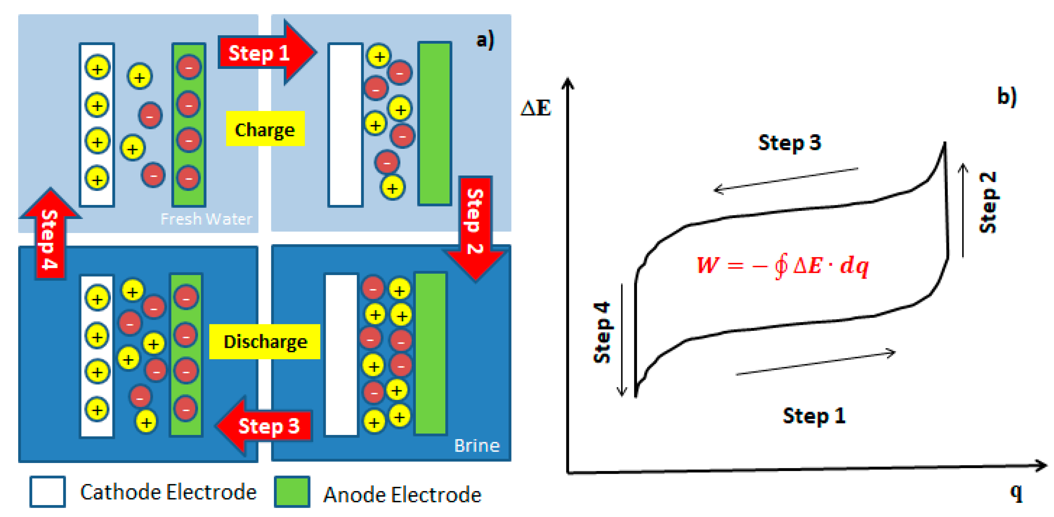
The mixing entropy battery proposed by Fabio La Mantia operates under a process by which anionic and cationic electrodes, selectively interact with Cl− and Na+ ions in several steps. In step 1, the battery is charged when M+ and A− ions are removed from the respective electrodes in a low ionic strength solution. In step 2, the recovery solution is exchanged for the concentrated solution, generating an increase in cell voltage or open circuit potential; this phenomenon is known as “Voltage Rise” [1,2,4,5,7,11,19,22,26]. In step 3, the battery is discharged with this high potential, capturing the M+ ions and A− from the concentrated solution, interspersing these ions within the crystalline structure of both electrodes at a constant current and in a closed circuit, generating energy. Finally, in step 4, the concentrated solution is exchanged for a recovery solution with low ionic force, leaving the device ready to start a new cycle. During steps 2 and 4, there is no power consumption or generation. Energy extraction, W, is given by the following expression:
where is the applied current, is the charge, and is the time. During the ion capture and release stage, energy extraction (W) is given by the sum of thermodynamic and kinetic contributions according the following expression:
where is the equilibrium potential of the electrochemical system, is the overpotential of the device, and and are the energy consumption products of the thermodynamic and kinetic contribution, respectively. Kinetic effects are usually related to overpotentials and are essential in determining the amount of energy extracted, on the other hand, kinetic limitations come hand in hand with mass diffusion processes.
3. Energy Consumption in the Process of Mixing Entropy Battery (MEB)
The different electrode arrays designs for MEB that have been proposed and successfully applied can be classified as selective exchange and salt capturing methods. The selective exchange is based on an ion intercalation reaction in Prussian Blue Analogue (PBA) while the salt capturing is based on conversion of Ag to AgCl [27]. In accordance with Equation (14) the salt capturing method operates using FePO4 and Ag as electrodes interacting with Li+ and Cl−, respectively. The selective exchange method operates with one selective electrode capable of capturing only metal cations different than Li+, in agreement with the following reaction:
The thermodynamic contribution to the energy consumption (Wth), depends on the method used for the metal ion recovery from the solution. In particular, the equilibrium voltage during step 1 and step 3, according to Figure 1, and the methods are given by the following Nernst equations.
3.1. Thermodynamic Energy Consumption
The thermodynamic energy consumption (Wth), depends on the method used for the metal recovery, in this case salt caturing and selective exchange methods.
3.1.1. Salt Capturing Method
For the salt capturing method, the equilibrium voltage during charge and discharge steps is given by the following Nernst equations, which describe the equilibrium condition of the reaction (14).
The thermodynamic energy consumption per mole of Li+ transferred from the brine to the recovery solution, using the salt capturing method, can be calculated by integrating along steps 1 and 3:
where, c is concentration and V is volume of the solution.
3.1.2. Selective Exchange Method
In the case of the selective exchange method the equilibrium voltage during charge and discharge steps is given by the following Nernst equations, which describe the equilibrium condition of the reaction (25).
The subscript M refers to the metal cation. The thermodynamic energy consumption per mole of Li+ transferred from the brine to the recovery solution,, using the selective exchange method is:
where q indicates the charge stored in the active material, qmax is the maximum charge stored in the active materials during step 1 and is the formal potential of the reaction, which is dependent on the state of charge. The concentration of ions can be considered constant during step 1 and during step 3. The concentration of the ions can change significantly.
3.2. Kinetic Energy Consumption
The kinetic energy consumption (Wk), is correlated to the overvoltage in the electrochemical device, η. The overvoltage can be divided in three contributions, according to the following equation:
where is the potential drop in the electrolyte, is the overvoltage product charge transfer and is the overpotential product mass transfer. These overpotentials depend on the materials, species involved in the reaction, electrolyte solution and the electrodes materials.
The depends on the geometry of the electrochemical device, as well as on the concentration and nature of the ions present in the solution. During step 1 the concentration of the ions in solution does not change significantly, so that the potential drop in the electrolyte can be described by the following equations:
3.2.1. Salt Capturing Method
For the salt capturing method, the drop potential in the electrolyte () related to the reaction (14) is given by the following equations.
3.2.2. Selective Exchange Method
For the selective exchange method, the drop potential in the electrolyte () related to the reaction the reaction (25) is given by the following equations.
where is the initial resistivity of the recovery solution at the beginning of step 1, is the resistivity of the solution during step 3 and, and are the distance between electrodes and A is the surface area of the electrode. It is assumed that the electrodes are two parallel plate of the same dimensions and that all the cations have similar mobility, ui.
also is known as the surface overvoltage for both electrodes. In step 3 this overpotential is independent of the electrochemical method. This condition changes only for the salt capturing method in step 1, because of the continuous change in the concentration of the ions in the recovery solution.
The is caused by the transport of reacting and produced species during the electrochemical reaction and strongly depends on the electrochemical method used. In the case of the salt capturing and selective exchange method, the concentration overvoltage during steps 1 and 3 is given by the following:
3.2.3. Salt Capturing Method
For the salt capturing method, the concentration overvoltage for reactants and products () related to the reaction (14) is given by the following equations.
3.2.4. Selective Exchange Method
For the selective exchange method, the concentration overvoltage for reactants and products () related to the reaction the reaction (25) is given by the following equations.
where Di is the diffusion coefficient of species i and is the thickness of diffusion layer. Surface overvoltage is strongly dependent on the nature and structure of the active materials used for the recovery of metal cations as Li+. It is difficult to predict the value of the surface overvoltage, however it is known that once AgCl is formed on the surface of Ag metal, ηS largely increases [5,27,28] and actually represents one of the highest energy losses in the system. Prussian Blue Analogue (PBA) as NiHCF presents a very fast kinetic and very low ηS.
The kinetic energy consumption is always positive and it is observed that the kinetic energy consumption relative to the resistance of the electrolyte and the diffusion process is, in general, small and similar for the two methods when the current density is constant.
4. Natural Solutions as Electrolyte for MEB
For the correct MEB operation, it is possible to use the following concentrated electrolytes: seawater, hot-springs water, lake water, underground water, geothermal water, oilfield brine, relict hydrothermal brine, brine from reverse osmosis plants and high-altitude salt-lake brine.
The majority of publications about MEB for harvesting blue energy use a solution of between 0.5 and 0.6 M NaCl as a concentrated solution (seawater), and 0.02 to 0.024 M NaCl as a diluted solution (river water) [1,4,5,6,11,12,19,23]. Seawater is the most abundant electrolyte on Earth; nearly 97.5% of the Earth is covered by seawater, but just 2.5% is fresh water. Obviously, seawater has a significantly higher salt concentration than fresh water due to the existence of salts in the form of dissolved ions at a concentration of about 35 g/L of total salts [29]. On the other hand, the geothermal water composition is characterized by the macro elements of the reservoir rock and the subsurface environment to which it is exposed most of the time. Like seawater, the NaCl is the most predominant salt component present in dissolved form adding salinity to the geothermal water. The total dissolved solids in high temperature geothermal water (>150 °C) were reported to be between 2.5 to 81 g/L, while for medium temperature geothermal waters it is (90–150 °C). The total dissolved solids were reported to be between 1.1 to 8.2 g/L. The highest concentrations, of between 260 to 280 g/L for geothermal water, have been reported in California, USA [30]. Another interesting alternative is the use of brines from shallow saline lakes or evaporation ponds located in the high altitude plateau of the Salar de Atacama basin in Chile. The total dissolved solid in these brines, around 165 g/L, contains Mg2+, Ca2+, Na+, K+, SO42−, Cl− and HCO3− as major constituents and also B+, Li+ and Cu2+ as trace elements. Nevertheless, other elements as Co, Cr, Fe, Mn, Mo, Pb, V, and Zn—although confirmed—are not well documented [31]. Table 1, shows the composition of major constituents of different natural brines that have a potential use in this technology.
The main technical limitation of this technology is the fresh water availability. Most publications indicate the use of river water as dilute salt solution. An alternative for fresh water is the use of urban wastewater, which was reported by Meng Ye et al. [22], but no indication was given for the water quality.
5. Intercalation Materials as Cathode Electrode in MEB
The behavior of a battery is based on the redox reactions which take place on the surface of the electrodes. The equilibrium potential of these reactions depends on the concentration of the electroactive components in the electrolyte solution, which ideally follows a Nernstian response, so that the change of the solution leads to the voltage rise that can be exploited for the energy extraction [1].
Valid candidates to replace the “sodium-capturing electrode” have been found in the PBA family. These materials have an open crystal structure composed of a face-centered cubic setting of transition metal cations octahedrally coordinated to hexacyanometallate groups. Large interstitial “A sites” within the structure can accommodate zeolitic water or alkali insertion ions. This results in a general chemical formula of , where A is an alkali cation, P is the N-coordinated transition metal cation, is the hexacyanometallate anion and represents a hexacyanometallate vacancy. Both the N-coordinated and C-coordinated transition metals can be electrochemically active in this structure. The PBA framework structure has wide channels between the A sites, allowing for the rapid insertion and removal of monovalent and multivalent cations. Some researches verify intercalation of Na+, Li+, Mg2+, Cu2+, Al3+ and NH4+ in PBA [7,8,36,37,38].
The principal cathode materials, based on PBAs tested in the MEB, are Cobalt Hexacyanoferrate (CoHCF) [23], Nickel Hexacyanoferrate (NiHCF) [27,39] and Copper Hexacyanoferrate (CuHCF) [7,8,11,13,18] to capture Na+ ions from seawater. The use of materials in the PBA family in MEBs is an advantage, because most are low-cost cathode materials [40].
5.1. Cobalt Hexacyanoferrate (CoHCF)
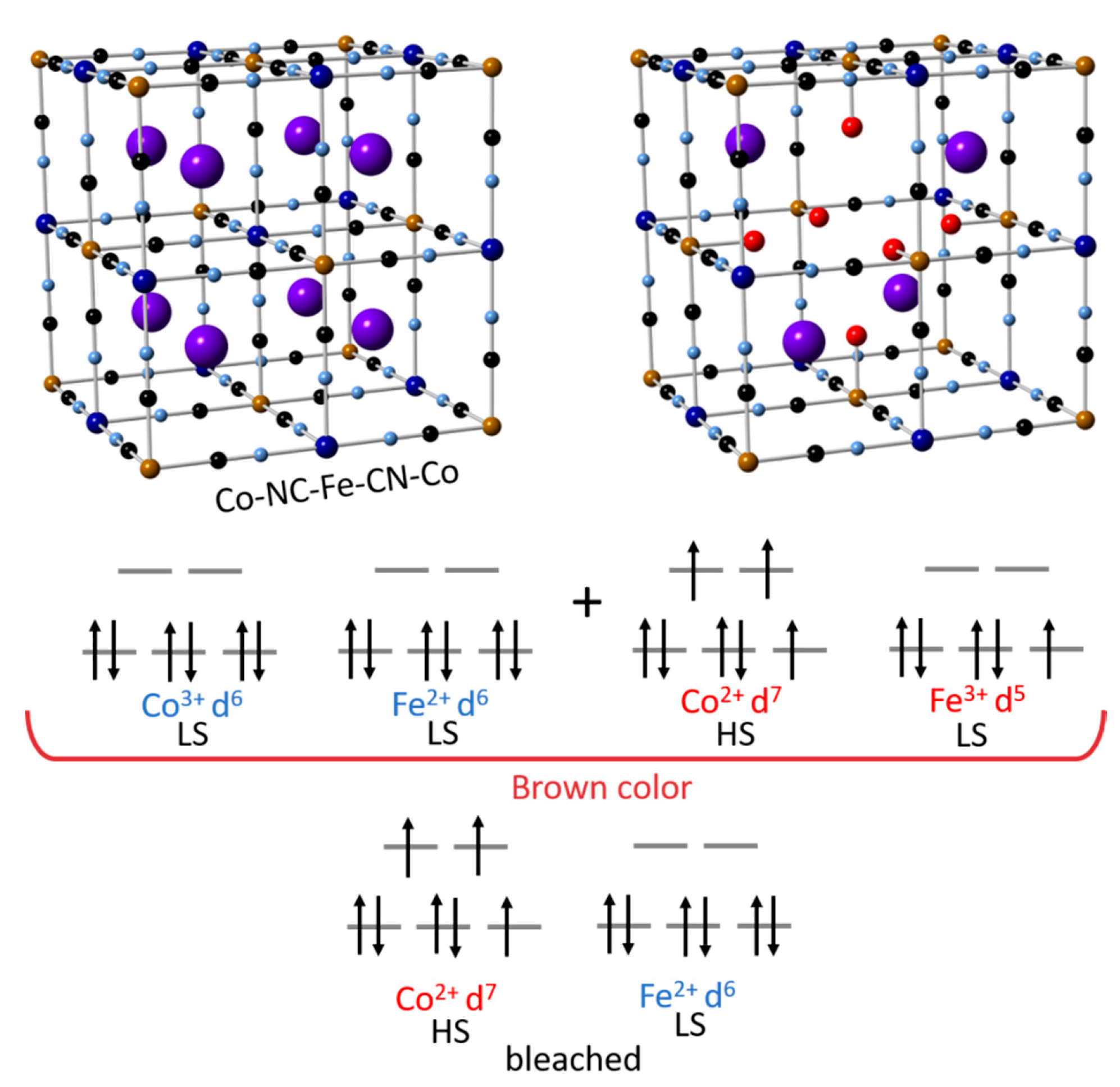
Cobalt Hexacyanoferrate is one of the most interesting inorganic polymers. As shown in Figure 2, the redox process in CoHCF involves two different metal transition ions (Fe and Co). Unlike other materials of the same class, the redox process is driven by a metal to metal charge transfer mechanism. The Fe3+ and Co3+ makes it possible to observe both redox couples, Fe3+/ Fe2+ and Co3+/ Co2+ in the same material [41]. The principal intercalation reaction for Na+ ions is shown in the following reactions [23].
5.2. Nickel Hexacyanoferrate (NiHCF)
Nickel hexacyanoferrate consists of Fe and Ni ions connected by CN- bridges, generating a face-centered cubic structure. In this coordination compound, Ni2+ ions are located in crystal lattice sites occupied by high spin Fe3+ species in PBA. Each Fe ion coordinates with six carbon atoms, whilst each Ni ion coordinates with six nitrogen atoms. This arrangement produces an open-channel network along the three crystallographic axes, which allows for electroinsertion/electrodeinsertion of hydrated cations [27,39,44], as shown in Figure 3.
5.3. Copper Hexacyanoferrate (CuHCF)
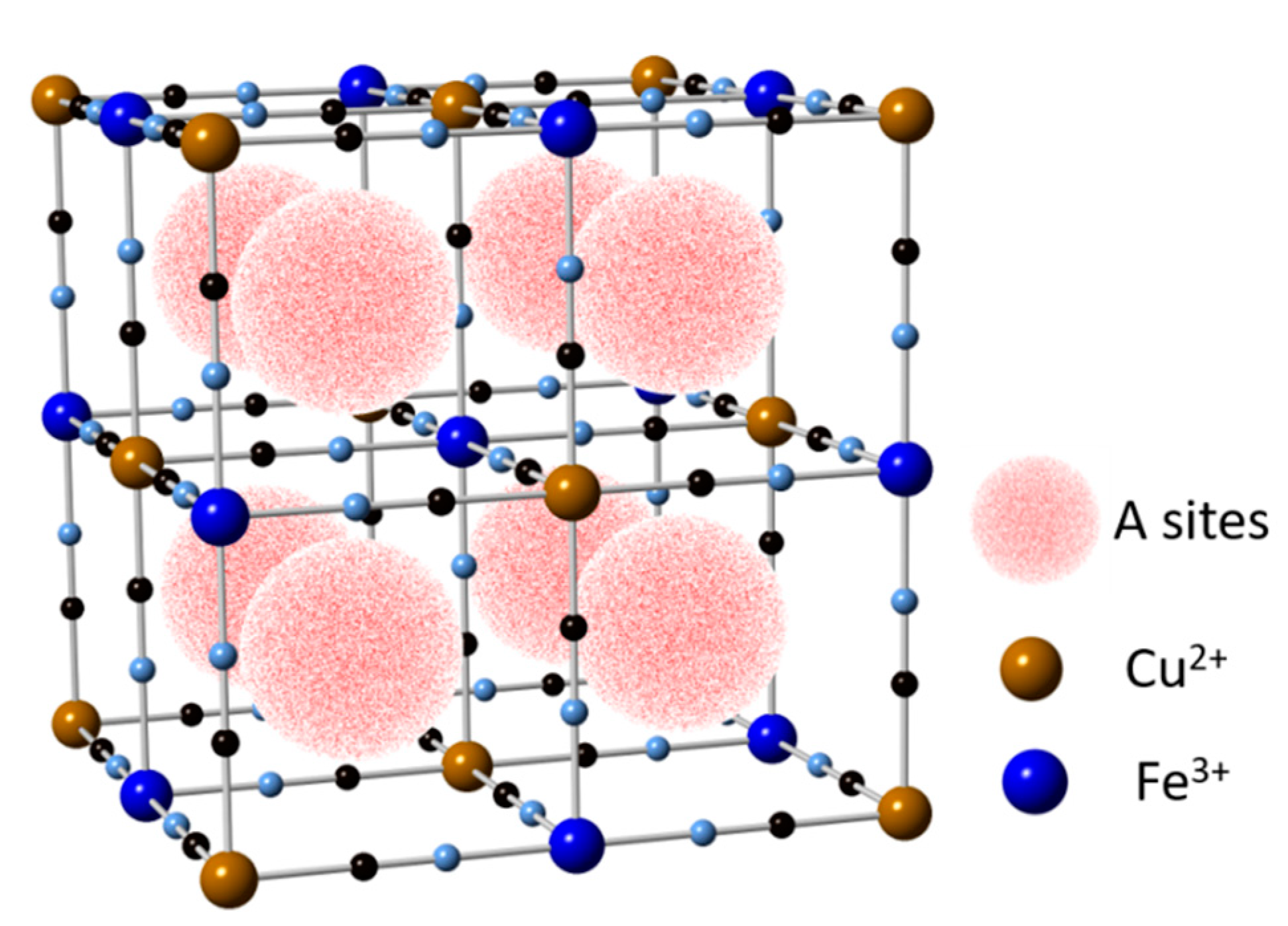
This material showed a very good potential for mono and multivalent ions insertion and de-insertion characteristics. The capacity of CuHCF is insensitive to the ionic valency of the intercalating species provided. The concentration of intercalating ions in the electrolyte is more than the moles of the active material, this is because the number of ions inserted in the CuHCF depends on the balancing of charge with the number of available Fe2+ ions in the crystal structure, thereby limiting the cell capacity [8,13].
The reduction reaction corresponds to the collation process, and oxidation to the deintercalation process of Na+ ions. When the reduction process occurs, the reduction of Fe3+ ions to Fe2+ occurs simultaneously. At the same time, for the Na+ ion insertion process to be carried out within the crystalline structure of PBA, a lot of energy or work force will be needed, because in some PBAs the K+ ions occupy the center of the structure, as shown in Figure 4. During the oxidation process of Fe2+ to Fe3+ the deintercalation of Na+ ions will simultaneously occur.
Nowadays, PBAs are the cheapest cathode materials used in MEBs [40]. These materials don’t need high temperatures for synthesis because the material can be obtained at ambient temperature. Table 2 shows the most typical cathode materials used in MEB, indicated in the bibliography, and their operation conditions.
5.4. LiFePO4
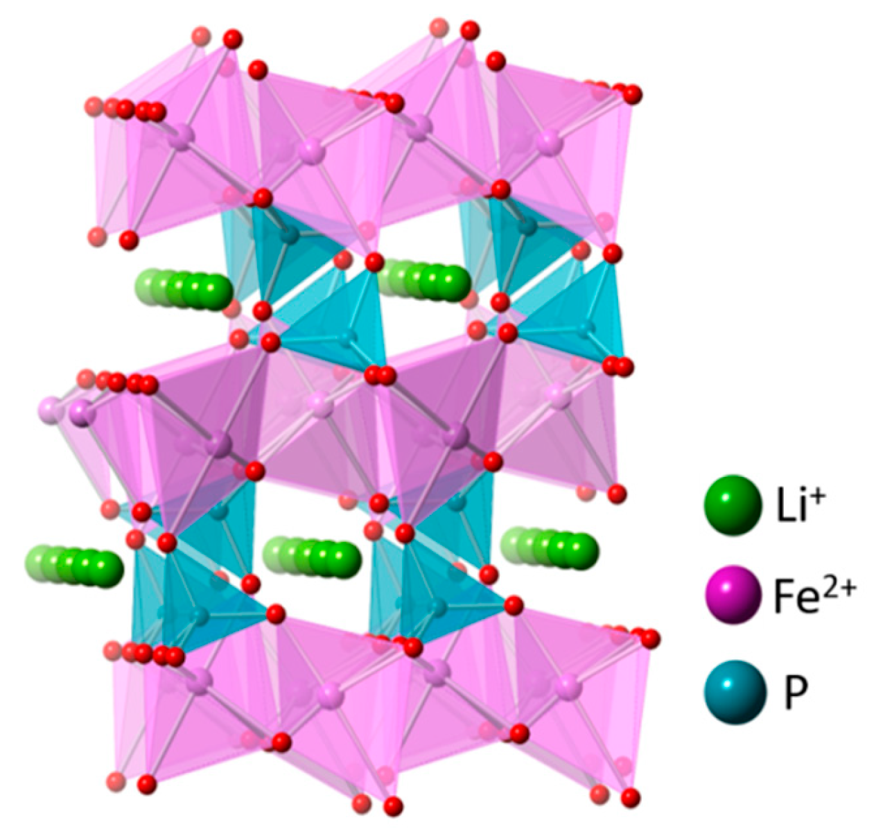
The topotactic insertion of Li+ ions into heterosite (FePO4) is used successfully in lithium iron phosphate rechargeable battery. The LiFePO4 in the olivine phase is more stable than insertion of Na+, accepting lithium in preference to other cations on exposure in the aqueous solution. The high mobility of Li+ in the structure shows the fast discharge reaction, suggesting that Li+ insertion is controlled by the time of exposure of FePO4 material to solutions that contain Li+, indicated by the fast kinetic. The insertion of Na+ into heterosite FePO4 involves a large volumetric expansion, structural rearrangement, and low kinetics and the presence of a small amount of Li+ ions. The FePO4 matrix seems to block the insertion of Na+ [5,47,48], as shown in Figure 5.
5.5. Na2Mn5O10
Manganese dioxide-based materials are used as supercapacitor and are studied for their good electrochemical behavior, high specific capacitance, environmental-friendliness and low cost. Among the large quantities of manganese oxides reported in literature are Li-Mn-O, Na-Mn-O or Mg-Mn-O systems, which received extensive attention due to their tunnel or layered crystal structures, facilitating the cation intercalation/deintercalation [49] as shown in Figure 6. A Mn4+/Mn3+ redox system involving a single-electron transfer is responsible for the MnO2 pseudocapacitive behavior. The energy storage mechanism is generally related to the accumulation of ionic charges in the double layer at the electrode/electrolyte interface. In aqueous electrolytes the charge/discharge is described by the following equation [5,50]:
where represents metal cations as Na+, Li+ and K+. The reaction mechanism implies an adsorption/desorption process of cations at the material surface and/or an insertion/extraction process of cations into the bulk material. The charge storage consists of a complete reduction of Mn4+/Mn3+ energy extracted from , depending strongly on the quality of the material collector interface of the supercapacitor [50].
5.6. Na4Mn9O18
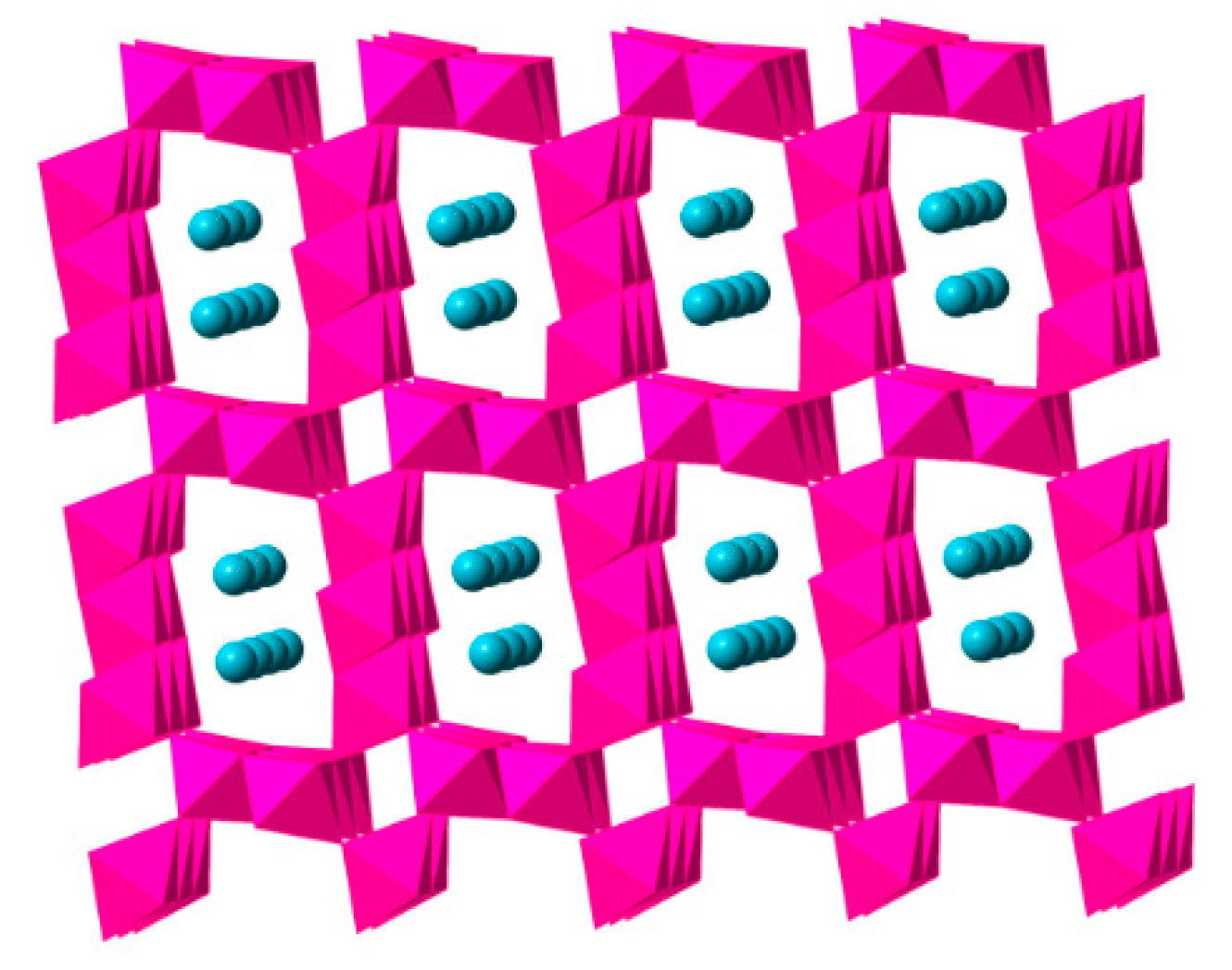
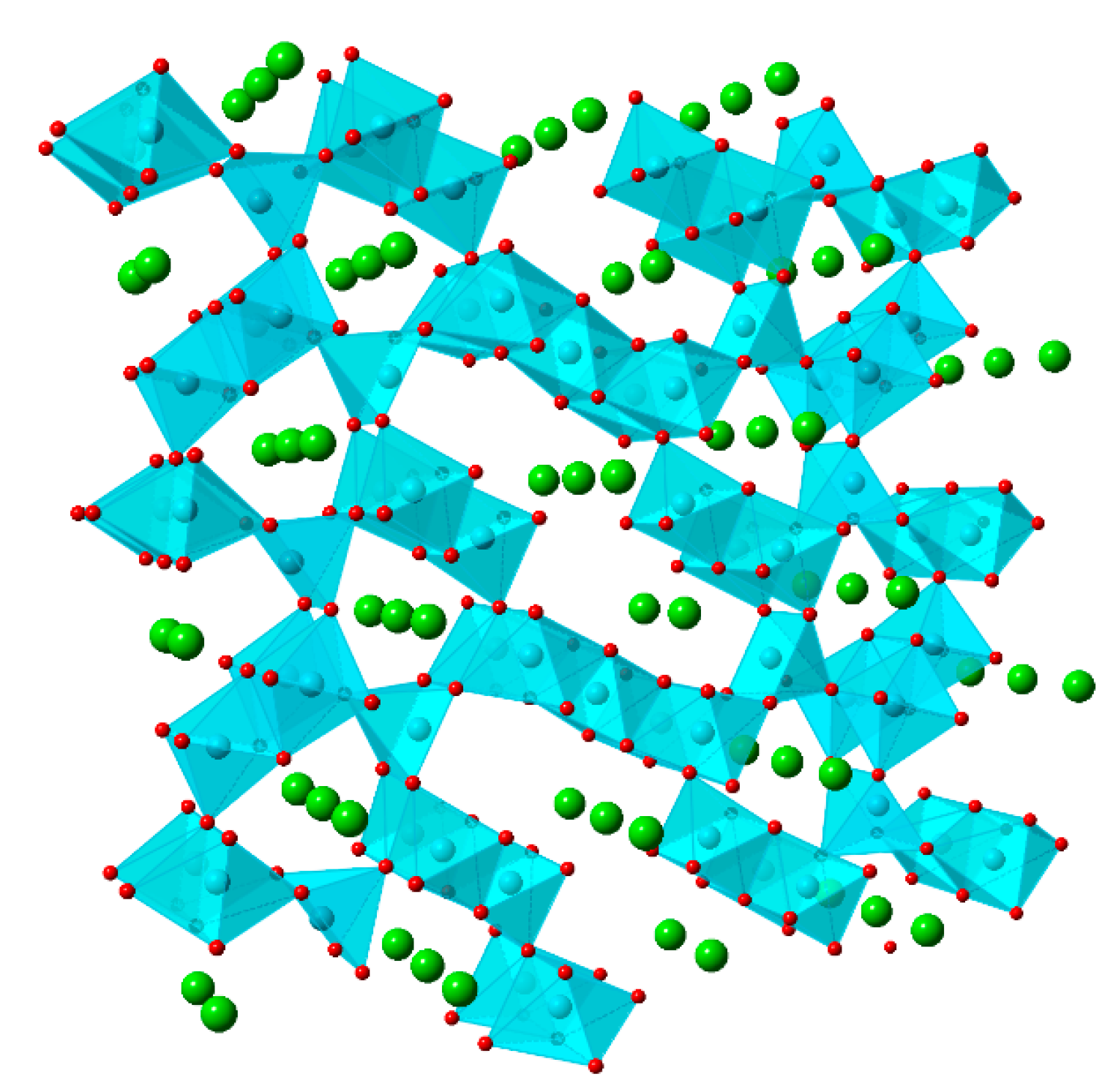
The sodium manganese oxide has been considered as a promising cathode material in the Na+ ion battery. The orthorhombic structure of sodium manganese oxides is dependent on the sodium content, and it is made of MnO5 square pyramids and MnO6 octahedral as shown in Figure 7. The manganese ions are located in two different environments, leading to three available sites in which two Na+ ions occupy the large s-shaped tunnels while another Na+ ion occupies a smaller tunnel [51], according to the follow equation [22]:
Table 3 shows the most typical battery materials and the principal parameters used in the MEB for operation and design of the electrochemical device. These parameters deliver the constructive form of the MEB. The volume of the test battery indicates that the technology is of laboratory scale and has not yet been tested on a pilot scale. All MEB use parallel plate electrodes in their design, and the electrode distance is also important because the internal resistance of electrolytes is reduced by decreasing the distance between electrodes [22].
Table 4 shows information about the suspension preparation procedure for the active material in the cathode electrodes. The active material is mixed with a polyvinylidene fluoride (PVDF) as a binder, carbon black or graphite and N-Methyl-2-pyrrolidone (NMP), 1-Methyl-2-pyrrolidinone or dimethyl sulfoxide as solvent.
Table 5 shows information regarding the blue energy recovery obtained by various researchers using different active materials for the MEB.
Many groups are focusing on a synthesis of new material electrodes with high specific capacity and cycling steadiness. Also, efforts have been directed to simplify electrode manufacturing processes. The most commonly used electrode materials have been modified by elemental doping, coating and composting with other materials like LiNiMnCoO2 [52]. These imply high ion diffusivity, enhancement in conductivity, ionic mobility and high retention capacity during the charging/discharging process. According to the reaction mechanisms of electrode materials, the materials can be divided into two groups, namely insertion and conversion type materials [53]. The literature shows that insertion materials are more promising materials because a robust crystalline structure, enlarged diffusion channel and easier pathways for ion insertion and removal are achieved. These provide a long-term cycling stability and high rate capability in comparison with conversion electrodes like Ag or Bi. These characteristics imply excellent stability and good safety performance for the intercalation material, and therefore are a preferred choice in commercial batteries [54].
6. Anode Materials Used in MEB
The anode materials used in MEB devices must have a very good redox behavior in contact with Cl− ions, as the intercalation or reaction of the electrodes with Cl− will result in energy storage. The silver electrode is a precious metal that reacts with Cl− to produce AgCl in addition to side complexation reactions, not only with chloride but also with sulfate in seawater. Searching alternative anode electrodes is essential for the development of MEBs.
6.1. Silver
Silver (Ag) electrodes are the most popular anodic electrodes [13] used in MEBs because of their reversibility and adaptability features in the presence of Cl− ions. The reason is that the anodic AgCl phase formation can take in an electrochemical window devoid of oxygen evolution reaction [55]. Unfortunately, AgCl phase formation takes place through many different forms of parallel reactions, as follows:
The typical anodic reactions n = 1 (n = 1,2,3) with thermodynamic stabilities [56] take place according to the following equations [5,22,27,28,54,55,56]:
The equilibrium concentration of the total soluble Ag+ is about 8.9 ppm, almost 100 times the U.S EPA secondary drinking water standard of 0.1 ppm. Ag+ is known to cause adverse health effects, including argyria, argyrosis, liver and kidney damage [22]. At present, the behavior of Ag in hypersaline solutions such as Atacama brines has not yet been studied.
Over 500 mV, the anodic current increases, due to the occurrence of reactions with the OH− ion at pH 7 or close to neutral, according to the following equation [57,58]:
AgCl formation mechanisms on the Ag surface electrode have been identified as a two-dimensional monolayer that is formed in the first adsorption/desorption cycle. After that, the AgCl phase or thin film grows by nucleation on the first layer as shown in Figure 8. During the formation of AgCl film over the Ag substrate, the overpotential gradually increases due to the resistance of deposit film. The overpotential fluctuation has been attributed to the cracking and healing of the AgCl layer or the dissolution of AgCl deposit accompanying the deposit growth [60,61,62].
6.2. Bismuth Oxychloride (BiOCl)
In 2019 G. Tan et al. [13] presented Bismuth Oxychloride (BiOCl) as an alternative to the Ag metal as anode. BiOCl has a tetragonal structure as shown in Figure 9 and is composed of a layer of Cl−, Bi3+ and O2- ions, and was successfully employed in chloride ion batteries and faradic deionization systems as chloride (Cl−) release/capture electrodes. BiOCl showed two kinds of reversible reactions due to Cl− transfer during cycling: (i) a major conversion reaction in which BiOCl transformed to Bi metal and Bi2O3, and (ii) a minor intercalation process that BiOCl charged to BiOCl1-x (x > 0) [61]. The principal reaction that occurs during charge and a discharge step is:
6.3. Polypyrrole (PPy)
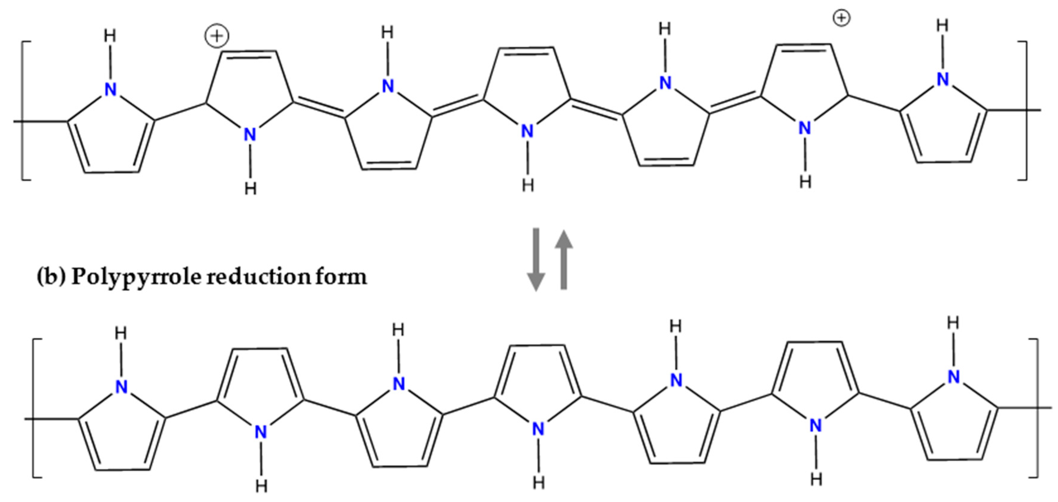
This compound is another promising material successfully tested as anode electrode [39,62,63]. The PPy material as an organic conducting polymer has been implemented with pyrrole-based polymers in which anionic dopants are incorporated upon preparation of the anode electrode as shown in Figure 10. The PPy is insoluble in aqueous electrolytes [63] and due to its wide potential window, complemented with high electron conductivity and good mechanical properties, has a wide potential range of technological applications [64]. The following mechanism of anion doping occurs by means of the following expression:
The conductivity of these conjugated polymers can be enhanced by oxidation of their chains. Oxidation/reduction processes also known as doping/de-doping are commonly accompanied by an ion flow in the electrode/solution interface, which maintains the electroneutrality of the polymer matrix [64]. The first step is the coordination of the anions from the electrolyte with the PPy chains during oxidation, which are then released during reduction. The reaction potentially of PPy depends on the particular doping anion. The Ag/PPy electrode consists of silver particles dispersed in PPy and was used in a MEB by Gomes et al. [39].
The Table 6 shows the anode materials that used until now in MEB technology. The difference between them is the energy consumption in the process of capturing the Cl−. Under similar conditions, the AgCl and BiOCl needed much more energy than PPy without considering that Ag has a higher cost than Bi and PPy. The costs are 3 USD/kg, 9.8 USD/kg and 553 USD/kg for PPy, Bi and Ag respectively [40,66].
7. Conclusion and Outlooks
Salinity gradient energy or blue energy using MEBs is clearly a plausible alternative to renewable energy around the world. In comparison with classical marine energies based on the mechanical action of waves and coastal wind, the blue energy presents interesting advantages related to reduced installation and material costs and corrosion protection requirements in coastal areas. However the working conditions in coastal areas pose a challenge for an MEB installation to overcome long term exposure to humidity with high salinity, wave action, splash and high corrosive stress, which together give rise to very fast corrosion in important sectors of a plant, increasing, as a result, the cost of this alternative energy harvesting [67]. The latest developments in this area, towards new and more efficient blue energy devices, encourage new ideas for the development of environmentally friendly projects. While blue energy is closely related to the recovery of chemical energy from the mixture of seawater and the river water that flows into the sea, it is also true that it is possible to consider other alternatives, such as the following:
- (a)
- Synthetic or natural saline solutions such as altiplanic brines in South America can serve as electrolytes in areas where no rivers with considerable flows are available. This alternative opens the possibility for this technology to be used in nearby coastal areas, or high altitude salt lake brines, as is the case for many altiplanic places in South America.
- (b)
- Another possibility would be to consider rejection flows from reverse osmosis plants as concentrated NaCl solution and seawater as the diluted solution in arid places where there are no rivers or treatment plants that flow into the sea.
- (c)
- It is interesting to note that fresh water availability, which is the main restrictive factor to implement MEB technologies in arid places, can be overcome by using solar energy to obtain distilled water with complete recycling of the electrolyte to achieve conversion of solar energy into electrical energy. The solar distillation technologies are well known and have a historical record of applications in Northern Chile as far back as 1842 and worked effectively for 40 years [68]. This fresh water collection alternative would make harvesting energy from salinity gradient possible at lower costs and greater efficiency.
- (d)
- The use of wastewater effluents as a source of fresh water could be useful for obtaining electrical energy through MEBs. However, more research related to the behavior of electrodes in the presence of biological contaminants and free chlorine is needed.
Today the efforts of many researchers are focused on the search for new cathode materials capable of storing the greatest amount of energy with good reversibility as well as low over-potentials and the lowest self-shocks or electrical leaks. This condition enables a good response under high intensity charging and discharging cycles, in addition to lower operational costs that overall fulfill a requirement for an environmentally friendly technology.
The proof-of-concept for MEB studies tested with a combination of different electrolytes such as real wastewater effluent, fresh water or artificial recovery solutions; real or artificial seawater or brine; with Sodium Manganese Oxide (NMO) or Lithium Iron Phosphate (LFP) as a cationic electrode and Ag/AgCl as anionic electrode have been shown to have high energy recovery efficiency values (68 to 75%). Unfortunately, some drawbacks are that (i) the Ag/AgCl electrode is costly and partially soluble in seawater or hypersaline solutions such as Atacama brines, (ii) the NMO and LFP electrodes are also costly with a moderate specific capacity and (iii) the MEB operation requires a charging step with an upfront energy investment, increasing the operational complexity. A very convenient attribute is the open-framework structure belonging to PBA materials, that allows fast insertion/extraction of cations into/from the interstitial sites or crystal structure, evidenced by over 1000 charge/discharge cycles and lower cost (<1 USD/kg) [40].
It is interesting that anionic materials in electrochemical devices such as Bi/BiOCl, Ag/AgCl and PPy have not only been tested in MEB batteries but also in chloride sensors, deionization devices and Lithium recovery from brines. The initial high adsorption/desorption activity for Cl− ions exhibited by Ag/AgCl and BiOCl degrades during the cycles, as higher thermodynamic and kinetic energy consumptions gradually increase, whereby the recovered blue energy is reduced over time. The PPy that is the cheapest material (<3 USD/kg) [40] as anode electrode presents the best behavior when capturing Cl− ions during cycling, this being manifested as a lower energy consumption. In this potential range the PPy electrode also showed an excellent cycling performance that was close to 100% coulombic efficiency (ranging from 95.7 to 97.8%) and 92% capacity retention through 50 cycles [40].
Other reported electrodes made of inorganic materials such as [69,70,71], [72], [73], [74], [75], [76], [77], [78], [79], [80], [81] and [78] have been explored as active materials for Faradaic ions storage in electrochemical desalination devices.
Recently new anode materials have been reported and are under development, such as [82], [83,84], [83,84], [85], [86,87,88], [89] and [90].
Thus, at present development of the MEB technology, PBA and PPy seem to be the ideal candidates to be used as cationic and anionic electrode materials. Both have lower costs, overlapping potential range, sensitivity to NaCl and LiCl concentration changes and excellent cycling performance and stability in aqueous solutions.
Author Contributions
Conceptualization, methodology, and writing-original daft preparation, F.G.; visualization, writing review and editing, L.C.; sources and editing, L.M.; visualization, writing review and editing, Á.S. All authors have read and agreed to the published version of the manuscript.
Funding
This research received no external funding.
Acknowledgments
The author would like to the Programa de Doctorado en Ingeniería de Procesos de Minerales of the University of Antofagasta, Chile.
Conflicts of Interest
The authors declare no conflict of interest.
References
- Marino, M.; Misuri, L.; Ruffo, R.; Brogioli, D. Electrode kinetics in the “capacitive mixing” and “battery mixing” techniques for energy production from salinity differences. Electrochim. Acta 2015, 176, 1065–1073. [Google Scholar] [CrossRef]
- Marino, M.; Misuri, L.; Carati, A.; Brogioli, D. Proof-of-Concept of a Zinc-Silver Battery for the Extraction of Energy from a Concentration Difference. Energies 2014, 7, 3664–3683. [Google Scholar] [CrossRef] [Green Version]
- Lee, J.; Yoon, H.; Lee, J.; Kim, T.; Yoon, J. Extraction of Salinity Gradient Energy using a Hybrid Capacitive-mixing System. ChemSusChem 2017, 10, 1600–1606. [Google Scholar] [CrossRef] [PubMed]
- Brogioli, D. Extracting renewable energy from a salinity difference using a capacitor. Physcal Rev. Lett. 2009, 058501, 31–34. [Google Scholar] [CrossRef]
- La Mantia, F.; Pasta, M.; Deshazer, H.D.; Logan, B.E.; Cui, Y. Batteries for Efficient Energy Extraction from a Water Salinity Difference. Nanoletters 2011, 11, 1810–1813. [Google Scholar] [CrossRef]
- Brogioli, D.; Ziano, R.; Rica, R.A.; Salerno, D.; Kozynchenko, O.; Hamelers, H.V.M.; Mantegazza, F. Exploiting the spontaneous potential of the electrodes used in the capacitive mixing technique for the extraction of energy from salinity difference. Energy Environ. Sci. 2012, 5, 9870–9880. [Google Scholar] [CrossRef] [Green Version]
- Kim, T.; Rahimi, M.; Logan, B.E.; Gorski, C.A. Evaluating Battery-like Reactions to Harvest Energy from Salinity Differences using Ammonium Bicarbonate Salt Solutions. ChemSusChem 2016, 9, 981–988. [Google Scholar] [CrossRef]
- Kim, T.; Rahimi, M.; Logan, B.E.; Gorski, C.A. Harvesting energy from salinity differences using battery electrodes in a concentration flow cell Harvesting energy from salinity differences using battery electrodes in a concentration flow cell. Environ. Sci. Technol. 2016. [Google Scholar] [CrossRef]
- Morais, W.G.; Gomes, W.J.A.S.; Huguenin, F. Neutralization Pseudocapacitors: An Acid-Base Machine. J. Phys. Chem. C 2016, 120, 17872–17877. [Google Scholar] [CrossRef]
- Hasan, K.N.; Khai, T.X.; Kannan, R.; Zakaria, Z.A. Harnessing Blue energy: A Review Techniques and Preliminary Analysis. MATEC Web Conf. 2017, 131, 04013. [Google Scholar] [CrossRef] [Green Version]
- Jia, Z.; Wang, B.; Song, S.; Fan, Y. A membrane-less Na ion battery-based CAPMIX cell for energy extraction using water salinity gradients. RSC 2013, 3, 26205–26209. [Google Scholar] [CrossRef]
- Sharma, K.; Kim, Y.H.; Yiacoumi, S.; Gabitto, J.; Bilheux, H.Z.; Santodonato, L.J.; Mayes, R.T.; Dai, S.; Tsouris, C. Analysis and simulation of a blue energy cycle. Renew. Energy 2016, 91, 249–260. [Google Scholar] [CrossRef] [Green Version]
- Tan, G.; Zhu, X. Polyelectrolyte-coated CuHCF and BiOCl electrodes for efficient salinity gradient energy recovery in capacitive mixing. Energy Technol. 2019, 8. [Google Scholar] [CrossRef]
- Logan, B.E.; Elimelech, M.; States, U. Membrane-based processes for sustainable power generation using water. Nature 2012. [Google Scholar] [CrossRef]
- Sales, B.B.; Liu, F.; Schaetzle, O.; Buisman, C.J.N.; Hamelers, H.V.M. Electrochemical characterization of a supercapacitor flow cell for power production from salinity gradients. Electrochim. Acta 2012, 86, 298–304. [Google Scholar] [CrossRef] [Green Version]
- Pattle, R.E. Production of Electric Power by Mixing Fresh and Salt Water in the Hydroelectric Pile. Nature 1954, 174, 660. [Google Scholar] [CrossRef]
- Clampitt, B.H.; Kiviat, F.E. Energy recovery from saline water by means of electrochemical cells. Sci. New Ser. 1976, 194, 719–720. [Google Scholar] [CrossRef]
- Jia, Z.; Wang, B.; Song, S.; Fan, Y. Blue energy: Current technologies for sustainable power generation from water salinity gradient. Renew. Sustain. Energy Rev. 2014, 31, 91–100. [Google Scholar] [CrossRef]
- Marino, M.; Kozynchenko, O.; Tennison, S.; Brogioli, D. Capacitive mixing with electrodes of the same kind for energy production from salinity differences. J. Phys. Condens. Matter 2016, 28, 114004. [Google Scholar] [CrossRef]
- Post, J.W.; Hamelers, H.V.M.; Buisman, C.J.N. Energy Recovery from Controlled Mixing Salt and Fresh Water with a Reverse Electrodialysis System. Environ. Sci. Technol. 2008, 42, 5785–5790. [Google Scholar] [CrossRef]
- Pasta, M.; Battistel, A.; Mantia, F. La Batteries for lithium recovery from brines. Energy Environ. Sci. 2012, 5, 9487–9491. [Google Scholar] [CrossRef]
- Ye, M.; Pasta, M.; Xie, X.; Cui, Y.; Criddle, S. Performance of a Mixing Entropy Battery Alternately Flushed with Wastewater Effluent and Seawater for Recovery of Salinity-gradient Energy - Suplementary Information. Energy Environ. Sci. 2014, 1–8. [Google Scholar]
- Tehrani, S.H.M.H.; Seyedsadjadi, S.A.; Ghaffarinejad, A. Application of electrodeposited cobalt hexacyanoferrate fi lm to extract energy from water salinity gradients. RSC Adv. 2015, 5, 30032–30037. [Google Scholar] [CrossRef]
- Nie, P.; Yuan, J.; Wang, J.; Le, Z.; Xu, G.; Hao, L.; Pang, G.; Wu, Y.; Yan, X.; Zhang, X. Prussian Blue Analogue with Fast Kinetics Through Electronic Coupling for Sodium Ion Batteries. Appl. Mater. Interfaces 2017, 9, 20306–20312. [Google Scholar] [CrossRef] [PubMed]
- Liao, J.; Hu, Q.; Yu, Y.; Wang, H.; Tang, Z.; Wen, Z.; Chen, C. Potassium-rich iron hexacyanoferrate/dipotassium terephthalate @carbon nanotube composite for K-ion full cells with optimized electrolyte. J. Mater. Chem. A 2017, 0, 19017–19024. [Google Scholar] [CrossRef]
- Rica, R.A.; Ziano, R.; Salerno, D.; Mantegazza, F.; van Roij, R.; Brogioli, D. Capacitive Mixing for Harvesting the Free Energy of Solutions at Different Concentrations. Entropy 2013, 15, 1388–1407. [Google Scholar] [CrossRef] [Green Version]
- Trocoli, R.; Bidhendi, G.K.; Mantia, F. La Lithium recovery by means of electrochemical ion pumping: A comparison between salt capturing and selective exchange. J. Phys. Condens. Matter 2016, 28, 114005. [Google Scholar] [CrossRef]
- Pasta, M.; Wessells, C.D.; Cui, Y.; La Mantia, F. A Desalination Battery. Nanoletters 2012, 12, 839–843. [Google Scholar] [CrossRef]
- Senthilkumar, S.T.; Go, W.; Han, J.; Thuy, L.P.T.; Kishor, K.; Kim, Y.; Kim, Y. Emergence of rechargeable seawater batteries. J. Mater. Chem. A 2019, 7, 22803–22825. [Google Scholar] [CrossRef]
- Gude, G. Geothermal Source for Water Desalination—Challenges and Opportunities; Butterworth-Heinemann: Oxford, UK, 2018; Volume 1, ISBN 9780128152447. [Google Scholar]
- Tapia, J.; González, R.; Townley, B.; Oliveros, V.; Álvarez, F.; Aguilar, G.; Menzies, A.; Calderón, M. Geology and geochemistry of the Atacama Desert. Antonie van Leeuwenhoek Int. J. Gen. Mol. Microbiol. 2018, 111, 1273–1291. [Google Scholar] [CrossRef]
- Bardi, U. Extracting Minerals from Seawater: An Energy Analysis. Sustainability 2010, 2, 980–992. [Google Scholar] [CrossRef] [Green Version]
- Cortecci, G.; Boschetti, T.; Mussi, M.; Lameli, C.H.; Mucchino, C.; Barbieri, M. New chemical and original isotopic data on waters from El Tatio geothermal field, northern Chile. Geochem. J. 2005, 39, 547–571. [Google Scholar] [CrossRef]
- Taylor, P.; Park, J.; Sato, H.; Nishihama, S. Solvent Extraction and Ion Exchange Lithium Recovery from Geothermal Water by Combined Adsorption Methods. Solvent Extr. Ion Exch. 2012, 30, 398–404. [Google Scholar] [CrossRef]
- Ogawa, Y.; Koibuchi, H.; Suto, K.; Inoue, C. Effects of the Chemical Compositions of Salars de Uyuni and Atacama Brines on Lithium Concentration during Evaporation. Resour. Geol. 2014, 64, 91–101. [Google Scholar] [CrossRef]
- Guduru, R.K.; Icaza, J.C. A Brief Review on Multivalent Intercalation Batteries with Aqueous Electrolytes. Nanomaterials 2016, 6, 41. [Google Scholar] [CrossRef]
- Yang, N.; Sun, H. Biocoordination chemistry of bismuth: Recent advances. Coord. Chem. Rev. 2007, 251, 2354–2366. [Google Scholar] [CrossRef]
- Ma, F.; Li, Q.; Wang, T.; Zhang, H.; Wu, G. Energy storage materials derived from Prussian blue analogues. Sci. Bull. 2017, 62, 358–368. [Google Scholar] [CrossRef] [Green Version]
- Gomes, W.J.A.S.; De Oliveira, C.; Huguenin, F. Energy Harvesting by Nickel Prussian Blue Analogue Electrode in Neutralization and Mixing Entropy Batteries. Langmuir 2015, 31, 8710–8717. [Google Scholar] [CrossRef]
- Ye, M.; Pasta, M.; Xie, X.; Dubrawski, K.L.; Xu, J.; Liu, C.; Cui, Y.; Criddle, C.S. Charge-Free Mixing Entropy Battery Enabled by Low-Cost Electrode Materials. ACS Omega 2019, 4, 11785–11790. [Google Scholar] [CrossRef] [Green Version]
- Berrettoni, M.; Giorgetti, M.; Zamponi, S.; Conti, P.; Ranganathan, D.; Zanotto, A.; Saladino, M.L.; Caponetti, E. Synthesis and Characterization of Nanostructured Cobalt Hexacyanoferrate. J. Phys. Chem. C 2010, 114, 6401–6407. [Google Scholar] [CrossRef]
- Kholoud, E.; Watanabe, H.; Takahashi, A.; Emara, M.M.; Abd-El-Nabey, B.A.; Kurihara, M.; Tajima, K.; Kawamoto, T. Cobalt haxacyanoferrate nanoparticles for wet-processed brown-bleached electrochromic devices with hydridization of high spin/low-spin phases. J. Mater. Chem. C 2017, 5, 8921–8926. [Google Scholar] [CrossRef]
- Martínez-García, R.; Knobel, M.; Balmaseda, J.; Yee-Madeira, H.; Reguera, E. Mixed valence states in cobalt iron cyanide. J. Phys. Chem. Solids 2007, 68, 290–298. [Google Scholar] [CrossRef]
- Wessells, C.D.; Peddada, S.V.; Huggins, R.A.; Cui, Y. Nickel Hexacyanoferrate Nanoparticle Electrodes For Aqueous Sodium and Potassium Ion Batteries. Nanoletters 2011, 11, 5421–5425. [Google Scholar] [CrossRef]
- Malecki, G.; Ratuszna, A. Crystal structure of cyanometallates Me3[Co(CN)6]2 and KMe[Fe(CN)6] with Me=Mn2+, Ni2+, Cu2+. Powder Diffr. 1999, 14, 25–30. [Google Scholar] [CrossRef]
- Loos-Neskovic, C.; Ayrault, S.; Badillo, V.; Jimenez, B.; Garnier, E.; Fedoroff, M.; Jones, D.J.; Merinov, B. Structure of copper-potassium hexacyanoferrate ( II ) and sorption mechanisms of cesium. J. Solid State Chem. 2004, 177, 1817–1828. [Google Scholar] [CrossRef]
- Intaranont, N.; Garcia-Araez, N.; Hector, A.L.; Milton, J.A.; Owen, J.R. Selective lithium extraction from brine by chemical reaction with battery materials. J. Mater. Chem. A 2014, 2, 6374–6377. [Google Scholar] [CrossRef]
- Biendicho, J.J.; West, A.R. Thermally-induced cation disorder in LiFePO4. Solid State Ionics 2011, 203, 33–36. [Google Scholar] [CrossRef] [Green Version]
- Liu, S.; Fan, C.; Zhang, Y.; Li, C.; You, X. Low-temperature synthesis of Na 2 Mn 5 O 10 for supercapacitor applications. J. Power Sources 2011, 196, 10502–10506. [Google Scholar] [CrossRef]
- Ghodbane, O.; Pascal, J.; Charles, I.; Montpellier, G.; Cnrs, U.M.R.; Aime, E. Microstructural Effects on Charge-Storage Properties in MnO 2 -Based Electrochemical. ACS Appl. Mater. Interfaces 2009, 1, 1130–1139. [Google Scholar] [CrossRef]
- Liu, X.; Zhang, N.; Ni, J.; Gao, L. Improved electrochemical performance of sol – gel method prepared Na 4 Mn 9 O 18 in aqueous hybrid Na-ion supercapacitor. J. Solid State Electrochem. 2013, 1, 1939–1944. [Google Scholar] [CrossRef]
- Jiang, X.; Sha, Y.; Cai, R.; Shao, Z. The solid-state chelation synthesis of LiNi1/3Co1/3Mn1/3O2 as a cathode material for lithium-ion batteries. J. Mater. Chem. A Mater. Energy Sustain. 2015, 00, 1–9. [Google Scholar] [CrossRef]
- Palacín, M.R. Recent advances in rechargeable battery materials: A chemist’s perspective. Chem. Soc. Rev. 2009. [Google Scholar] [CrossRef]
- Meng, J.; Guo, H.; Niu, C.; Zhao, Y.; Xu, L.; Li, Q.; Mai, L. Advances in Structure and Property Optimizations of Battery Electrode Materials. Joule 2017. [Google Scholar] [CrossRef] [Green Version]
- Bro, P.; Marincic, N.; Mallory, P.R.; Science, P. The High Rate Oxidation of Silver Electrodes in Chloride Solutions. J. Eletrochemical Soc. 1970, 116, 1338–1341. [Google Scholar] [CrossRef]
- Jaya, S.; Rao, T.P.; Rao, G.P. Mono- and multilayer formation studies of silver chloride on silver electrodes from chloride-containing solutions. J. Appl. Electrochem. 1987, 17, 635–640. [Google Scholar] [CrossRef]
- Margalit, N. Cathodes for Seawater Activated Cells. J. Electrochem. Soc. 1975, 122, 1005–1008. [Google Scholar] [CrossRef]
- Birss, V.I.; Smith, C.K. The anodic behavior the formation and reduction thin silver chloride films. Electrochim. Acta 1987, 32, 259–268. [Google Scholar] [CrossRef]
- Ha, H.; Payer, J. Electrochimica Acta The effect of silver chloride formation on the kinetics of silver dissolution in chloride solution. Electrochim. Acta 2011, 56, 2781–2791. [Google Scholar] [CrossRef] [Green Version]
- Jin, X.; Lu, J.; Liu, P.; Tong, H. The electrochemical formation and reduction of a thick AgCl deposition layer on a sil v er substrate. J. Electroanal. Chem. 2003, 542, 85–96. [Google Scholar] [CrossRef]
- Keramidas, G.; Voutsas, G.P.; Rentzeperis, P.I. The crystal structure of BiOCl. Zeitschrift für Krist. 1993, 205, 35–40. [Google Scholar] [CrossRef]
- Su, X.; Hatton, T.A. Redox-electrodes for selective electrochemical separations. Adv. Colloid Interface Sci. 2017, 244, 6–20. [Google Scholar] [CrossRef] [PubMed]
- Pasta, M.; Wessells, C.D.; Huggins, R.A.; Cui, Y. A high-rate and long cycle life aqueous electrolyte battery for grid-scale energy storage. Nat. Commun. 2012, 3, 1147–1149. [Google Scholar] [CrossRef] [PubMed] [Green Version]
- Morais, W.G.; Lima, G.; Gomes, W.J.A.S.; Huguenin, F. Electrochemical Systems for Renewable Energy Conversion from Salinity and Proton Gradients. J. Brazil Chem. Soc. 2018, 29, 934–947. [Google Scholar] [CrossRef]
- Stejskal, J.; Trchova, M.; Bober, P.; Moravkova, Z.; Kopecky, D.; Vrñata, M.; Prokes, J.; Varga, M.; Watzlova, E. Polypyrrole salts and bases: Superior conductivity of nanotubes and their stability towards the loss of conductivity by deprotonation. RSC Adv. 2016, 6, 88382–88391. [Google Scholar] [CrossRef] [Green Version]
- Nam, D.; Choi, K. Bismuth as a New Chloride-Storage Electrode Enabling the Construction of a Practical High Capacity Desalination Battery. J. Am. Chem. Soc. 2017, 139, 11055–11063. [Google Scholar] [CrossRef]
- Musabikha, S.; Ketut Aria Pria Utama, I. Mukhtasor Corrosion in the Marine Renewable Energy: A Review. Proc. Ocean. Mech. Aerosp. 2016, 3, 121–128. [Google Scholar]
- Kristoferson, L.A.; Bokalders, V. Solar Water Distillation. In Renewable Energy Technologies; Pergamon: Oxford, UK, 1986; pp. 215–218. [Google Scholar]
- Miyai, Y.; Ooi, K.; Katoh, S. Recovery of Lithium from Seawater Using a New Type of Ion-Sieve Adsorbent Based on MgMn2O4. Sep. Sci. Technol. 1988, 23, 179–191. [Google Scholar] [CrossRef]
- Liu, M.; Rong, Z.; Malik, R.; Canepa, P.; Jain, A.; Ceder, G.; Persson, K.A. Spinel compounds as multivalent battery cathodes: A systematic evaluation based on ab initio calculations. Energy Environ. Sci. 2015, 8, 964–974. [Google Scholar] [CrossRef] [Green Version]
- Mao, M.; Gao, T.; Wang, C. A critical review of cathodes for rechargeable Mg batteries. Chem. Soc. Rev. 2018, 47, 8804–8841. [Google Scholar] [CrossRef]
- Kim, S.; Lee, J.; Kim, C.; Yoon, J. Na2FeP2O7 as Novel Material for Hybrid Capacitive Deionization. Electrochim. Acta 2016, 255, 369–378. [Google Scholar] [CrossRef]
- Huang, Y.; Cheng, F.; Guo, L.; Yang, H.Y. Ultrahigh Performance of Novel Electrochemical Deionization System based on NaTi2(PO4)3/rGo Nanocomposite. J. Mater. Chem. A 2017, 5, 18157–18165. [Google Scholar] [CrossRef]
- Chen, F.; Huang, Y.; Guo, L.; Ding, M.; Yang, H.Y. A dual-ion electrochemistry deionization system based on AgCl-Na0.44MnO2 electrodes. Nanoscale 2017, 9, 10101–10108. [Google Scholar] [CrossRef] [PubMed]
- Guo, L.; Mo, R.; Shi, W.; Huang, Y.; Leong, Z.Y.; Ding, M.; Chen, F.; Yang, H.Y. Prussian blue anode for high performance electrochemical deionization promoted by faradic mechanism. Nanoscale 2017, 9, 13305–13312. [Google Scholar] [CrossRef] [PubMed]
- Desai, D.; Beh, E.S.; Sahu, S.K.; Vedharathinam, V.; Van, Q.; De Lannoy, C.; Jose, A.P.; Volkel, A.R.; Rivest, J. Electrochemical Desalination of Seawater and Hypersaline Brines with Coupled Electricity Storage. ACS Energy Lett. 2018, 3, 375–379. [Google Scholar] [CrossRef]
- Choi, S.; Chang, B.; Kim, S.; Lee, J.; Yoon, J.; Choi, J.W. Battery Electrode Materials with Omnivalent Cation Storage for Fast and Charge-Efficient Ion Removal of Asymmetric Capacitive Deionization. Adv. Funct. Mater. 2018, 1802665, 1–9. [Google Scholar] [CrossRef]
- Lee, J.; Kim, S.; Kim, C.; Yoon, J. Hybrid capacitive deionization to enhance the desalination performance of capacitive techniques. Energy Environ. Sci. 2017, 00, 1–7. [Google Scholar] [CrossRef]
- Zhu, X.; Xu, W.; Tan, G.; Wang, Y. Concentration Flow Cells for Efficient Salinity Gradient Energy Recovery with Nanostructured Open Framework Hexacyanoferrate Electrodes. Energy Technol. Environ. Sci. 2018, 3, 5571–5580. [Google Scholar] [CrossRef]
- Li, G.; Yang, Z.; Jiang, Y.; Jin, C.; Huang, W.; Ding, X. Towards polyvalent ion batteries: A zinc-ion battery based on NASICON. Nano Energy 2016, 25, 211–217. [Google Scholar] [CrossRef]
- Qu, Q.T.; Shi, Y.; Tian, S.; Chen, Y.H.; Wu, Y.P.; Holze, R. Short communication A new cheap asymmetric aqueous supercapacitor: Activated carbon // NaMnO 2. J. Power Sources 2009, 194, 1222–1225. [Google Scholar] [CrossRef]
- Shaz, M.; Van Smaalen, S.; Palatinus, L.; Hoinkis, M.; Klemm, M.; Horn, S.; Claessen, R. Spin-Peierls transition in TiOCl. Physcal Rev. Lett. 2005, B71, 100405. [Google Scholar] [CrossRef] [Green Version]
- Gao, P.; Zhao, X.; Zhao-karger, Z.; Diemant, T.; Behm, R.J.; Fichtner, M. Vanadium Oxychloride / Magnesium Electrode Systems for Chloride Ion Batteries. Appl. Mater. Interfaces 2014, 6, 22430–22435. [Google Scholar] [CrossRef] [PubMed]
- Gao, P.; Reddy, M.A.; Mu, X.; Diemant, T.; Zhang, L.; Zhao-karger, Z.; Sai, V.; Chakravadhanula, K.; Clemens, O.; Behm, R.J.; et al. Rechargeable Batteries VOCl as a Cathode for Rechargeable Chloride Ion Batteries Angewandte. Angew. Chem. Int. Ed. 2016, 55, 4285–4290. [Google Scholar] [CrossRef] [PubMed]
- Zhao, X.; Zhao-karger, Z.; Wang, D.; Fichtner, M. Metal Oxychlorides as Cathode Materials for Chloride Ion Batteries. Angew. Chem. Int. Ed. 2013, 52, 13621–13624. [Google Scholar] [CrossRef]
- Maguire, J.A.; Banewicz, J.J. Direct Intercalation of Alkali Metal Ions in FeOCl. Mat. Res. Bull 1984, 19, 1573–1580. [Google Scholar] [CrossRef]
- Zhao, X.; Li, Q.; Yu, T.; Yang, M.; Fink, K.; Shen, X. Carbon incorporation effects and reaction mechanism of FeOCl cathode materials for chloride ion batteries. Nat. Publ. Gr. 2016, 6, 1–8. [Google Scholar] [CrossRef] [Green Version]
- Lind, M.D. Refinement of the Crystal Structure of Iron Oxychloride. Acta Cryst 1970, B26, 1058–1062. [Google Scholar] [CrossRef]
- El-Halim, A.M.A.; Fawzy, M.H.; Stay, A. Saty Cyclic voltammetric behaviour and some surface characteristics of the lead electrode in aqueous NaCl solutions. J. Electroanal. Chem. 1991, 316, 275–292. [Google Scholar] [CrossRef]
- Zuo, W.; Zhu, W.; Zhao, D.; Sun, Y.; Li, Y.; Liu, J.; Lou, X.W. Bismuth oxide: A versatile high-capacity electrode material for rechargeable aqueous metal-ion batteries. Energy Environ. Sci. 2016, 9, 2881–2891. [Google Scholar] [CrossRef]
Figure 1.
(a) Schematic representation of the systematic work of the mixing entropy battery (MEB). (b) Typical Brogioli cycle, where the battery cell voltage (ΔE) vs charge (q) is represented. The closed integral represents the removable energy (W) of cycle.
Figure 1.
(a) Schematic representation of the systematic work of the mixing entropy battery (MEB). (b) Typical Brogioli cycle, where the battery cell voltage (ΔE) vs charge (q) is represented. The closed integral represents the removable energy (W) of cycle.

Figure 2.
Schematic view of the CoHCF crystal structure and expected valence/spin states for the respective redox state (ICSD no. 157486). Illustration based from [42,43].

Figure 3.
Crystal structure of Nickel Hexacyanoferrate (NiHCF) (ICSD no. 89338). Illustration based on [44,45].

Figure 4.
Schematic structure of Copper Hexacyanoferrate (CuHCF) (ICSD no. 99499). Illustration based from [36,46].

Figure 5.
Crystal structure of olivine LiFePO4 in projection [001] (ICSD no. 56291).

Figure 6.
Schematic illustration of the crystal structure of Na2Mn5O10. This structure consists of purple octahedral units MnO6 shared by corners and/or edges, where Na+ occupies positions within channels formed by octahedrals units (JCPDS 27-0749).
Figure 6.
Schematic illustration of the crystal structure of Na2Mn5O10. This structure consists of purple octahedral units MnO6 shared by corners and/or edges, where Na+ occupies positions within channels formed by octahedrals units (JCPDS 27-0749).

Figure 7.
Schematic illustration of the crystal structure of Na4Mn9O18. The Mn atoms form alternated octahedron MnO6 and tetrahedron MnO4 to form a several channels where diffusion of Li+ ions occurs (MP-1094147).
Figure 7.
Schematic illustration of the crystal structure of Na4Mn9O18. The Mn atoms form alternated octahedron MnO6 and tetrahedron MnO4 to form a several channels where diffusion of Li+ ions occurs (MP-1094147).

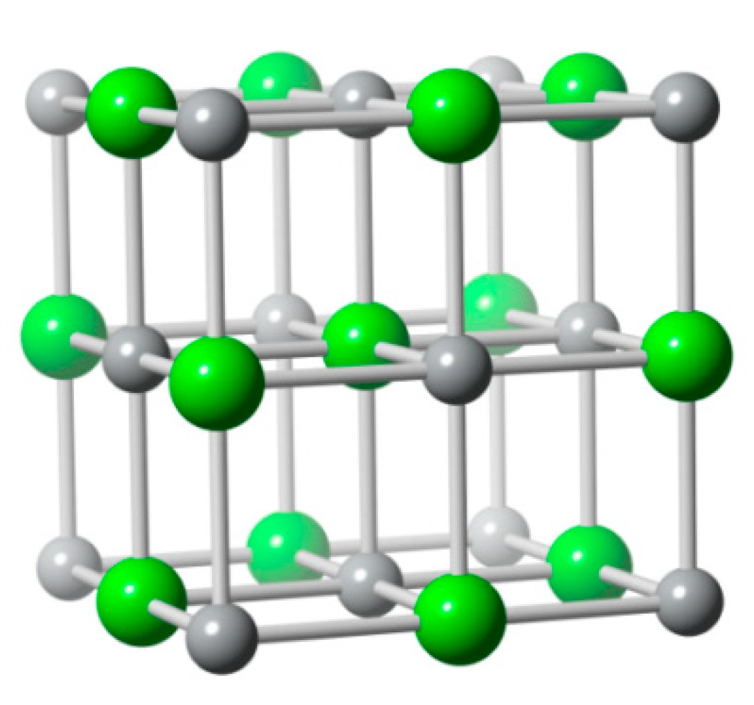
Figure 8.
The AgCl structure, a FCC unit cell with two ions (ICSD no. 56538) (Ag and Cl− are gray and green atoms respectively) per lattice point.
Figure 8.
The AgCl structure, a FCC unit cell with two ions (ICSD no. 56538) (Ag and Cl− are gray and green atoms respectively) per lattice point.

Figure 9.
Schematic 2D layer structure of BiOCl (ICSD no. 74502).

Figure 10.
Structure of Polypyrrole for respective redox states. Illustration based from [65].
Figure 10.
Structure of Polypyrrole for respective redox states. Illustration based from [65].


Table 1.
Main ion compositions of natural brines.
| Ref. | Natural Source | Cl− [ppm] | Na+ [ppm] | Mg2+ [ppm] | Ca2+ [ppm] | Li+ [ppm] |
|---|---|---|---|---|---|---|
| [29,32] | Seawater | 19.345 | 10.752 | 1.195 | 0.416 | 0.179 |
| [33,34] | Geothermal | 7.899 | 4.459 | 1.700 | 250 | 34,27 |
| [35] | Atacama Brine | 198.000 | 42.700 | 40.500 | 368 | 1.820 |
Table 2.
Prussia blue analogue material as cathode in MEBs.
| Ref. | PBA | Electrode Area [cm²] | Range Potential [V] | Range Density Current [A/cm²] | N° Cycle | Gain Voltage [V] |
|---|---|---|---|---|---|---|
| [11] | CuHCF | 5 | 0.2–0.65 | ±0.1 | 10 | 0.102 |
| [7] | CuHCF | 7 | 0–0.8 | ±0.2 | 20 | 0.172 |
| [8] | CuHCF | 3 | 0–0.9 | ±0.5 | - | 0.172 |
| [13] | CuHCF | 1 | - | ±0.2 | 50 | - |
| [23] | CoHCF | 1.3 | 0–1.1 | ±0.01 | 30 | 0.153 |
| [39] | NiHCF | 1 | 0–0.6 | ±0.01 | - | - |
Table 3.
Battery materials used as cathodes in MEBs.
| Ref. | BM | Electrode Area [cm²] | Volume MEB | Range Potential [V] | Electrode Distance [mm] | Range Density Current [A/cm²] | N° Cycle |
|---|---|---|---|---|---|---|---|
| [cm³] | |||||||
| [5] | LiFePO4 | 2 | 0.35 | 0–0.5 | 10 | ± 0.5 | 100 |
| [5] | Na2Mn5O10 | 2 | 0.35 | - | 10 | ± 0.25 | 100 |
| [1] | Na2Mn5O10 | 1 | - | - | 0.6 | - | - |
| [22] | Na4Mn9O18 | 9 | 1.5 | - | 1.7 | ± 0.03 | 12 |
| [3] | Na4Mn9O18 | 3.01 | 0.06 | 0–0.6 | 0.2 | ± 0.5 | 3 |
Table 4.
Preparation of battery material and PBA for cathodes in MEBs.
| Ref. | Active Material | Synthesis Method | Covering Method | Active Material [%] | Substrate | Electrode Mass [mg /cm²] |
|---|---|---|---|---|---|---|
| [5] | LiFePO4 | Polymeric Synthesis | Drop Casting | 80 | Carbon Cloth | 25 |
| [22] | Na4Mn9O18 | Solid State Reaction | Ink Coating | 85 | Carbon Cloth | 14 |
| [1] | Na2Mn5O10 | Pachini Method | Doctor Blade | 80 | Graphite | 8 |
| [7] | MnO2 | Co-Precipitation | Doctor Blade | 70 | Graphite Sheet | 34 |
| [11] | CuHCF | Dropwise | Spread | 90 | Carbon Plate | 5 |
| [7] | CuHCF | Co-Precipitation | Doctor Blade | 70 | Graphite Sheet | - |
| [8] | CuHCF | Co-Precipitation | Doctor Blade | 70 | Graphite Foil | 4.4 |
| [13] | CuHCF | Co-Precipitation | Spread | 80 | Carbon Paper | 4.8 |
| [23] | CoHCF | Co-Precipitation | Electrodeposition | - | CPE | 0.193 |
| [39] | NiHCF | Co-Precipitation | Hand Painting | 80 | Carbon Cloth | - |
Table 5.
Blue energy recovery using different cathode materials.
| Ref. | Active Material | Relevant Characteristics | Reversible Capacity [mAh/g] | Efficiency [%] | Blue Energy Recovery | |
|---|---|---|---|---|---|---|
| Advantage | Disadvantage | |||||
| [5] | LiFePO4 | High Stability | Poor E.C | 120 | - | 13.5 µW/cm2 |
| [22] | Na4Mn9O18 | High Capacity Retention | Low Charge Capacity | 113 | 68 | 0.65 kW/m3 |
| [5] | Na2Mn5O10 | High Surface Area | Low Charge Capacity | - | 75 | 10.5 µW/cm2 |
| [11] | CuHCF | High Capacity | High Irreversible Reaction | - | 69 | 13990 µW/cm2 |
| [7] | CuHCF | - | - | 411 mW/m2 | ||
| [8] | CuHCF | - | - | 6.3 mW/m2 | ||
| [13] | CuHCF | - | - | 87 mW/m2 | ||
| [23] | CoHCF | High Energy Density | Cell Voltage Limited (<1 V) | 130 | 65 | 4632 µW/cm2 |
| [39] | NiHCF | Efficient Energy Consumption | Low water recovery | 60 | - | 16.8 kJ/mol |
© 2020 by the authors. Licensee MDPI, Basel, Switzerland. This article is an open access article distributed under the terms and conditions of the Creative Commons Attribution (CC BY) license (http://creativecommons.org/licenses/by/4.0/).
Share and Cite
MDPI and ACS Style
Galleguillos, F.; Cáceres, L.; Maxwell, L.; Soliz, Á. Electrochemical Ion Pumping Device for Blue Energy Recovery: Mixing Entropy Battery. Appl. Sci. 2020, 10, 5537. https://doi.org/10.3390/app10165537
AMA Style
Galleguillos F, Cáceres L, Maxwell L, Soliz Á. Electrochemical Ion Pumping Device for Blue Energy Recovery: Mixing Entropy Battery. Applied Sciences. 2020; 10(16):5537. https://doi.org/10.3390/app10165537
Chicago/Turabian StyleGalleguillos, Felipe, Luis Cáceres, Lindley Maxwell, and Álvaro Soliz. 2020. "Electrochemical Ion Pumping Device for Blue Energy Recovery: Mixing Entropy Battery" Applied Sciences 10, no. 16: 5537. https://doi.org/10.3390/app10165537
Note that from the first issue of 2016, this journal uses article numbers instead of page numbers. See further details here.