Review

A Review of Self-Coherent Optical Transceivers: Fundamental Issues, Recent Advances, and Research Directions

1
Instituto de Telecomunicações, Campus Universitário de Santiago, University of Aveiro, 3810-193 Aveiro, Portugal
2
Department of Electronics, Telecommunications and Informatics, Instituto de Telecomunicações, Campus Universitário de Santiago, University of Aveiro, 3810-193 Aveiro, Portugal
3
Department of Electrical and Electronic Engineering, University of Melbourne, Melbourne, VIC 3010, Australia
*
Author to whom correspondence should be addressed.
Appl. Sci. 2021, 11(16), 7554; https://doi.org/10.3390/app11167554
Submission received: 20 July 2021 / Revised: 7 August 2021 / Accepted: 9 August 2021 / Published: 17 August 2021

Abstract

:
This paper reviews recent progress on different high-speed optical short- and medium-reach transmission systems. Furthermore, a comprehensive tutorial on high-performance, low-cost, and advanced optical transceiver (TRx) paradigms is presented. In this context, recent advances in high-performance digital signal processing algorithms and innovative optoelectronic components are extensively discussed. Moreover, based on the growing increase in the dynamic environment and the heterogeneous nature of different applications and services to be supported by the systems, we discuss the reconfigurable and sliceable TRxs that can be employed. The associated technical challenges of various system algorithms are reviewed, and we proffer viable solutions to address them.

1. Introduction

The advent of the fifth-generation (5G) network will impact different network entities, technologies, and the corresponding system as a whole. In this perspective, how the access networks, metro, core networks, high-performance cloud data center networks (DCNs), as well as the associated edge services and Internet of Things (IoT) devices are designed and deployed will be affected [1,2,3]. Furthermore, the emergence of IoT devices has brought about the unprecedented expansion of Internet connections [4,5]. Their proliferation and effective support for several innovative applications and services such as cloud computing, augmented reality (AR), massive machine-to-machine communication, and emerging web applications have considerably contributed to the growing increase in machine- and user-generated data traffic. In this regard, there has been a significant increase in the workload of the underlying DCNs that support the applications and services [6]. For effective service delivery, the ensuing traffic transportation requires a consistent increase in bandwidth both in the metro and long-haul optical fiber networks. Consequently, this imposes unprecedented bandwidth requirements on the transport networks. In this perspective, to satisfy diverse requirements such as robustness, flexibility, high bandwidth, and relatively reduced cost per unit bandwidth, bandwidth-efficient and cost-effective transmission systems have to be adopted [2]. One such effective solution is the intensity modulation with direct detection (IM-DD) transceivers (TRxs) scheme.
In addition, IM-DD-based transceivers offer various advantages such as low cost and ultra-low complexity. For instance, they require fewer optical components and present relaxed laser wavelength stability, without the need for complex digital signal processing (DSP) such as frequency offset compensation and carrier phase compensation [7]. These advantages make IM-DD-based schemes good candidates in the short-reach applications where a considerable amount of transceiver deployment is demanded. As a result, the associated cost of the short-reach transceivers is one of the main factors for network design and deployment, making it deserve significant consideration [8,9].
Moreover, the IM-DD receiver (Rx) sensitivity is independent of the state of polarization (SOP) and the carrier phase of the signal. This is advantageous as the polarization state randomly fluctuates in real system scenarios [10]. Nevertheless, the IM-DD system’s scalability and its spectral efficiency (SE) are significantly limited when the achievable information rate (AIR) is to be upgraded beyond 100 gigabits per second (Gb/s) per wavelength. This is mainly due to the associated one-dimensional (1D) modulation and detection constraints [8,11]. For instance, one of the fundamental bottlenecks of the conventional IM-DD system is the second-order nonlinearity. This is caused by the square law photodetection, and it limits the system capacity significantly. As a result of the lack of the phase diversity of the system, the transmission distance will be limited by chromatic dispersion (CD)-induced power fading [9] since the information is modulated on the optical intensity rather than the field [12]. Therefore, the conventional IM-DD system is incapable of field recovery (FR), which can support the digital compensation of fiber linear impairments and multidimensional modulation. On the other hand, the long-haul-based optical networks have attained a considerable AIR advancement for the multiterabit transmission with coherent (COH) transceiver system’s revitalization [8,11].
Furthermore, the polarization diversity feature of light can be exploited in the COH system to maximize the system SE and optimize the AIR [8]. With the aid of COH detection, optical receivers can perform field recovery of both the intensity and phase of the optical signal that is propagating over the fiber [8,13]. Furthermore, the coherent receiver (Co-Rx) is capable of the linear recovery of the signal with phase diversity. Fiber linear impairments can be effectively compensated through DSP. Other attractive features of the COH technology that facilitate multiterabit per second (Tb/s) capacity are the support for polarization multiplexing (PolMux), high-order modulation formats, dense wavelength division multiplexing (DWDM), and superchannels [12]. Apart from the offered increase in the degrees of freedom (DoFs) for optical modulations, the Co-Rx facilitates the digital compensation of fiber dispersion. This helps prevent the need for the complicated optical dispersion management [8,13].
It should be noted that polarization-diverse Co-Rx usually performs four-dimensional (4D) detection. This includes the signal in-phase (I) and quadrature (Q) of both polarizations X/Y. As a result, the offered dual-polarization (DP) field recovery by the implementation helps maximize the detection dimension in the single-mode fiber (SMF). Under random polarization variations of the fiber channel, it ensures a closed multiple-input multiple-output (MIMO) space without information loss. Nonetheless, the associated system complexity of the conventional Co-Rxs has been limiting its implementation to long-haul-based networks due to the cost, footprint, and power consumption of the transceiver [8,11,13].
In addition, based on the exhausting multiplexing dimension in the conventional direct-detection-based system and the consideration of the enhanced sensitivity of the COH detection along with its inherent WDM functionality, research attention has been shifting towards low-complexity implementations of COH systems. Consequently, to enhance the system AIR while maintaining the related cost-effective benefit, the short-reach networks should explore an appropriate compromise between 1D-based IM-DD and 4D-based COH detection schemes. In this perspective, some simplified and low-cost optical transceivers with good tradeoffs between the COH and the direct-detection-based systems have been presented [8,11,13].
In general, a promising system should be able to offer low-latency, low-cost, and small-footprint optical transceiver components that can support larger bitrates and operate over a considerable reach compared with the conventional IM-DD systems, while still being power efficient. To explore a suitable compromise between the cost-effective direct detection and spectrally efficient COH configurations, different potential solutions have focused on the optimization of the required components. For instance, some prevent the implementation of a local oscillator (LO) laser and extensive DSP that are normally employed in the conventional COH system, while still offering higher AIR values compared to the conventional direct detection [14]. In this regard, various configurations that are capable of realizing two-dimensional (2D) detection have been reported. Nonetheless, the solutions present notable limitations regarding the nonlinear signal–signal beat noise (SSBN) that is caused by the photodetection square function. The effect of this is a remarkable limitation in the system capacity. In an effort to address the 2D-based detection challenges, some configurations that leverage the direct detection scheme have been presented to perform three-dimensional (3D) detection [8,11,13].
Furthermore, notable advancements have been reported regarding simplified COH transceiver technologies. For instance, vertical-cavity surface-emitting lasers (VCSELs) or externally modulated lasers have been employed with analog signal processing to address the system complexity. Several polarization-independent quasicoherent receivers have been presented as a viable scheme to address the growing system requirements. The scheme is capable of attending to the system requirements in a cost-effective manner without the need for a DSP for real data recovery. Furthermore, based on the fact that the receiver sensitivity can be enhanced by the quasicoherent receiver, reduced optical power laser and inexpensive photodiodes can be employed rather than costly ones [15].
In addition, among the promising solutions that have been presented, a number of self-coherent (SCOH) systems have attracted considerable attention. In the SCOH systems, both the modulated signal and the carrier are copropagated at the transmitter (Tx). Moreover, at the receiver, the launched carrier from the transmitter not only serves as a reference, but also beats with the signal in the course of photodetection, resulting in SCOH detection [9]. Consequently, to achieve the system requirements, they depend on signal self-beating or beating between the signal and the copropagated continuous-wave (CW) laser tone from the transmitter. Many simpler DSP algorithms are usually employed compared to the conventional Co-Rx [14].
In this tutorial paper, we present a comprehensive review of high-performance, low-cost, advanced, and simplified optical transceiver paradigms that are suitable for different applications with the main focus on potential architectures for intra- and inter-DCN applications. The work majorly focused on the SCOH systems in which the signal self-beating or the beating between the modulated signal and the copropagated CW laser tone from the transmitter is exploited. In this context, effective means and related concepts of signal phase reconstruction based on the intensity information using the SCOH detection systems are presented. Furthermore, the means of addressing the fiber channel impairments such as the prevailing chromatic dispersion through optical channel linearization by the considered transceiver configurations are discussed. Moreover, the ability of the transceiver configurations to reduce both the system hardware and DSP complexity compared with the dual-polarized coherent (DP-COH) system while still enhancing the system SE in relation to the conventional IM-DD is comprehensively presented. Some cost-effective and simplified transceiver architectures that can effectively offer salient advantages such as high-SE and a high per-carrier interface rate (100 G per wavelength and beyond) over tens to hundreds of kilometers are discussed. With the DP-COH transmission scheme configuration being used as a benchmark, different potential schemes are compared considering various associated features such as the optical SEs, transceiver architectures, enabling DSPs, and the related receiver bandwidths. Moreover, based on the growing increase in the dynamic environment and the heterogeneous nature of the applications and services to be supported by the systems, reconfigurable and sliceable transceivers (transponders) that are capable of adapting a number of specified transmission parameters to accomplish exceptional tradeoffs among the network reach, power dissipation, and data rate are discussed with the main focus on their economics, advantages, and complexity. The transceivers can support different features such as flexible spectrum utilization and adaptive resource exploitation in a cost-effective manner. The associated system algorithms and technical challenges are reviewed with proffered viable solutions. Furthermore, different experimental demonstrations that were based on SCOH detection schemes are comprehensively reviewed.

1.1. Review of Related Works

Significant technological advancement has been made in the fields of optical communications regarding the optical field recovery of both the intensity and phase of light [16,17]. The field recovery capability majorly distinguishes COH detection from direct detection transmission counterpart [13]. With a number of research efforts, some direct detection systems can offer comparable detection dimensions to that of the COH system. However, the improvement in the system performance may be at the expense of either SSBN or SE wastage. To address the challenges, Kramers–Kronig (KK)-based direct detection system and Stokes vector direct detection (SV-DD) with better performance have been presented as alternatives to the conventional Co-Rxs [9,11,13,18,19,20,21,22]. These schemes have been experimentally demonstrated to be viable [11,13,19,21,22,23,24,25,26,27,28,29,30,31].
In addition, several papers have considered the related role of DSP in different aspects such as the estimation of the carrier phase, optical transceiver design, polarization state tracking, linear transmission impairment, and mitigation [7,10,22]. Moreover, to improve the system performance, the concepts of COH systems have been adapted to the direct detection schemes in some research efforts. For instance, various architectures have been proposed for direct phase modulation of the transmitter lasers [32], while a variety of cost-effective Co-Rx configurations have also been proposed [33,34]. Furthermore, a review and comparison of different optical SCOH subsystems with different channel linearization technologies and DSPs have been presented [9,11,12,13,14,19,26,33,34,35,36,37,38]. Different types and principles of the Stokes space field [11,13,39,40,41] and polarization [8,11,13,23,24,39] recoveries have been comprehensively discussed. Similarly, the Stokes vector receiver (SVR) that can perform a 3D detection without an LO has been presented [24]. Furthermore, the system capability to offer a data rate distance product beyond 10 Tb/s·km has been considered. For instance, potential 100 G per wavelength and beyond schemes for short-reach applications have been well compared [9,12,24,42]. Correspondingly, a comparative review of different potential schemes for intra- and inter-DCNs regarding the minimum required electrical bandwidth for the receivers and their support for digital chromatic dispersion compensation has been discussed [14].
Furthermore, to address the related spectral broadening of the KK algorithm that is due to nonlinear operations [18,43,44], some viable solutions have been presented. For instance, a modified DSP algorithm that does not require digital upsampling can be employed [18]. Similarly, mathematical approximations have also been presented to prevent the associated nonlinear operations’ execution [44,45,46]. Likewise, a low-complexity approach for the Hilbert filter implementation, where the associated convolution can be done directly, has been considered [21]. Furthermore, the related periodic spectral repetition and time domain singularity problem of the sampled Hilbert filter have been attended to through a modified Hilbert filter [21].
Moreover, one of the stringent system requirements for the conventional KK scheme is the minimum-phase condition in which a strong CW tone is demanded to realize an accurate field reconstruction. Consequently, this condition demands a high carrier-to-signal-power ratio (CSPR) [18,19,21,43,47]. This requirement deserves further research consideration as it presents an additional sensitivity penalty [48,49]. A number of research efforts have considered a means of reducing the required CSPR in the conventional KK system through modified KK receivers [48,49,50,51,52].
In addition, different carrier and optical single-sideband (SSB) signal generation have been presented [12,53,54,55,56]. For instance, the optical SSB signal generation regarding the offset SSB and virtual SSB (VSSB) has been presented [12]. Likewise, the SSB signal transmitters that are based on an electrical I Q mixer and optical I Q modulator are being studied [53]. Apart from the bias-induced generation being considered, digital virtual and optical generation schemes have been discussed [54]. Moreover, detailed theoretical derivations of the SSB-based modulation, as well as the relationship between the device parameters and the CSPR have been presented [55,56].
Furthermore, SSBN mitigation/receiver-based digital linearization schemes for the direct-detection-based systems have been considered [12,21,22,29,30,46,54,57,58,59]. For instance, the SSBN cancellation schemes based on the frequency gap insertion and iterative SSBN cancellation algorithm have been presented [12]. Similarly, the KK detection, iterative SSBN cancellation, and joint iterative SSBN cancellation have been analyzed [54]. Moreover, Refs. [22,29] focused on the performance of the direct-detection-based transceivers with electronic dispersion compensation (EDC) and DSP-based receiver linearization techniques. Furthermore, the receiver DSP (Rx-DSP) with the KK scheme and EDC has been considered [21,30,46]. The iterative SSBN cancellation and KK field reconstruction techniques have been analyzed [57].
As previously mentioned, several efforts have been presented in the literature regarding SCOH optical transceivers. Nevertheless, there are still some issues that demand further consideration. For instance, Ref. [47] focused on an increase in the DWDM system AIR through a corresponding increase in the SE. In the work, direct detection, constant-IM, and COH detection were studied, while other simplified schemes were not considered. Furthermore, the reviews in [7,10,22] centered mainly on the principle of COH optical communications and the related DSP. Furthermore, most of the configurations presented in [32,33,34,60] are mainly applicable to the passive access network systems. The supported transmission distance [32,33,60] or AIR [32,60] is also limited.
In spite of the fact that a variety of optical SCOH subsystems is being reviewed [9,11,12,13,14,19,26,33,34,37,38], the KK scheme and the associated signal processing chains have not been considered in the majority of the contributions. The optical SSB signal generation and mitigation were only presented briefly in a small number of works. Furthermore, the work in [24] focused on the SV-DD scheme and the signal recovery in the Stokes space, while other related SCOH subsystems were briefly reviewed. Likewise, the means of addressing spectral broadening in the KK algorithm were well attended to in [18,21,44,45,46]; however, most of them did not consider the demand for a strong CW tone, but also contributed to the issue [43]. Although measures by which the required CSPR in the conventional KK system can be lowered have been presented [48,49,50,51,52], the spectral broadening and the need to reduce the required digital upsampling have not been considered. Despite the fact that a joint optimization for the CSPR and DSP resampling rate has been considered [30,61], detailed information regarding the fundamental concept demands further consideration. Apart from the fact that the presented work in [14] was brief, some salient concepts of the simplified transceivers such as carrier/SSB signal generation, SSBN mitigation, spectral broadening, CSPR optimization, and field and polarization recoveries were not discussed. Moreover, the great majority of the contributions focused on one- or two-optical-SSB-signal generation [12,53,54,55,56], while most also presented one or two SSBN mitigation/digital linearization schemes [12,21,22,29,30,46,54,57,58,59]. Furthermore, in [55,56], the SSB signal generation was well presented, while little or no consideration was given to the SSBN mitigation/digital linearization schemes.

1.2. Contributions

As previously mentioned, there have been substantial contributions in the literature regarding optical transceiver systems. However, due to the continuous development in the field and the usual space constraints for publications, an all-inclusive research effort has not been presented on the simplified optical transceiver systems to support high-speed short- and medium-reach use cases. Consequently, a comprehensive tutorial in this area is highly imperative. This will enable researchers to have in-depth knowledge regarding the related requirements, technologies, architectures, and challenges of optical transceiver systems. Besides being abreast of the developments in the area, they will be able to proffer viable solutions to various network demands. Furthermore, the proffered insightful recommendations will be handy tools in practical system design. In light of this, this paper is a step towards bridging the gap of knowledge regarding the SCOH optical transceiver systems for short- and medium-reach applications. It presents not only a comprehensive tutorial on the optical transceiver architectures, but also considers the requirements for a simplified optical transceiver architectural evolution along with a piece of broad information on the technicalities of different related challenges and potential solutions. Moreover, the need for per-wavelength AIR enhancement is discussed, and different transceiver architectures that are capable of supporting 100 G per wavelength and beyond, at comparatively longer transmission distances and in a cost-effective way, are presented. Consequently, this paper not only complements the contributions of the existing survey and tutorial papers on the SCOH optical transceiver systems, but also covers more concepts with in-depth clarifications. In this context, the main contributions of this tutorial paper are as follows:
(i)
An extensive analysis of the associated short-reach system features and enabling technologies that demand novel transceiver architectures and DSP techniques are presented. In this context, an overview of high-speed short-reach systems regarding their classifications, advanced optoelectronic devices, potential modulation formats, requirements, and challenges are well considered;
(ii)
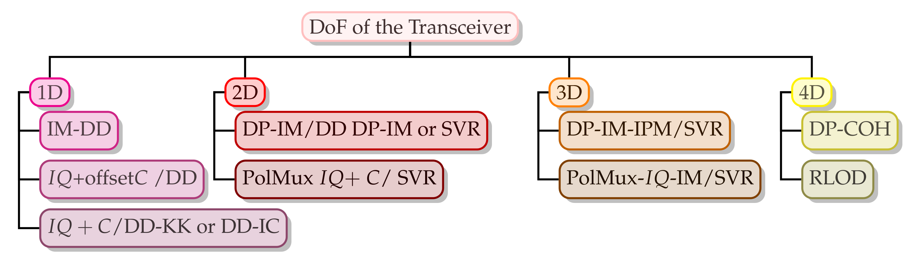
A comprehensive tutorial on the optical transceiver architectures and their classifications based on the DoF is presented. Furthermore, research efforts towards simplified and cost-effective architectures are well discussed. Furthermore, the requirements for a simplified transceiver architectural evolution from 1D to 4D and the related technical challenges are discussed with potential solutions being proffered;
(iii)
In addition to a comparison among different detection schemes, we present a detailed SCOH system classification based on the detection schemes, as well as the adopted polarization and modulation schemes at the transmitter. Furthermore, we give a comprehensive discussion of their relative advantages compared to the conventional IM-DD and COH systems. Furthermore, their respective technical limitations are considered, and potential solutions are proffered;
(iv)
Moreover, besides the presented comprehensive studies on the carrier and optical SSB signal generation, a distinct classification of the schemes based on the adopted generation approaches is provided. Furthermore, the related features of the schemes are extensively discussed considering the required frequency gap, associated CSPR, achievable SE, required optical filter, and hardware complexity;
(v)
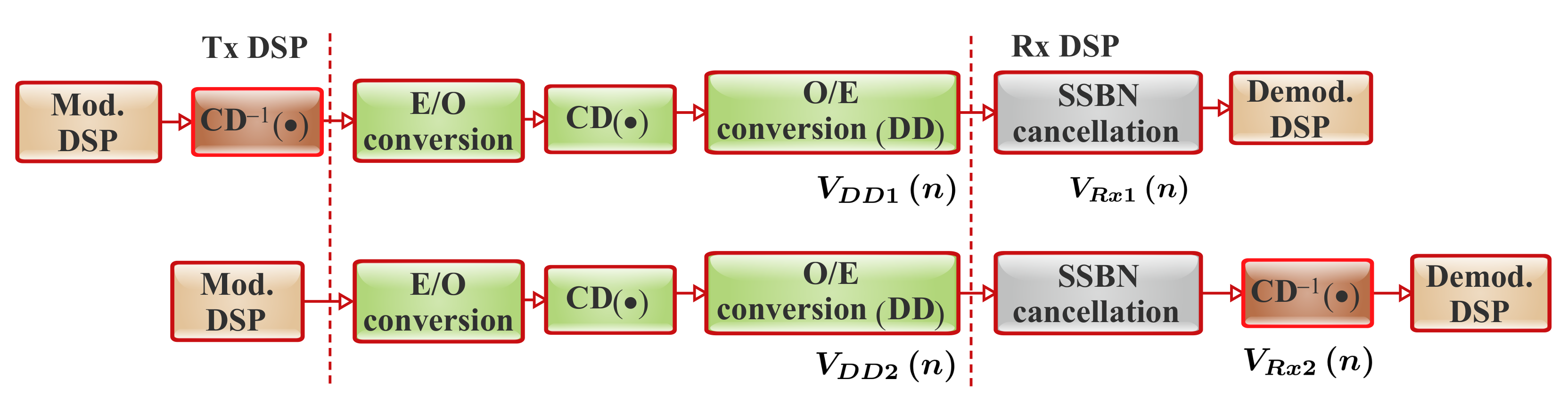
Furthermore, apart from an in-depth discussion on the SSBN mitigation concepts, the SSBN mitigation/receiver-based digital linearization schemes for the direct-detection-based systems are clearly presented with the main focus on the performance of transmitter-based EDC (Tx-EDC) and receiver-based EDC (Rx-EDC) systems;
(vi)
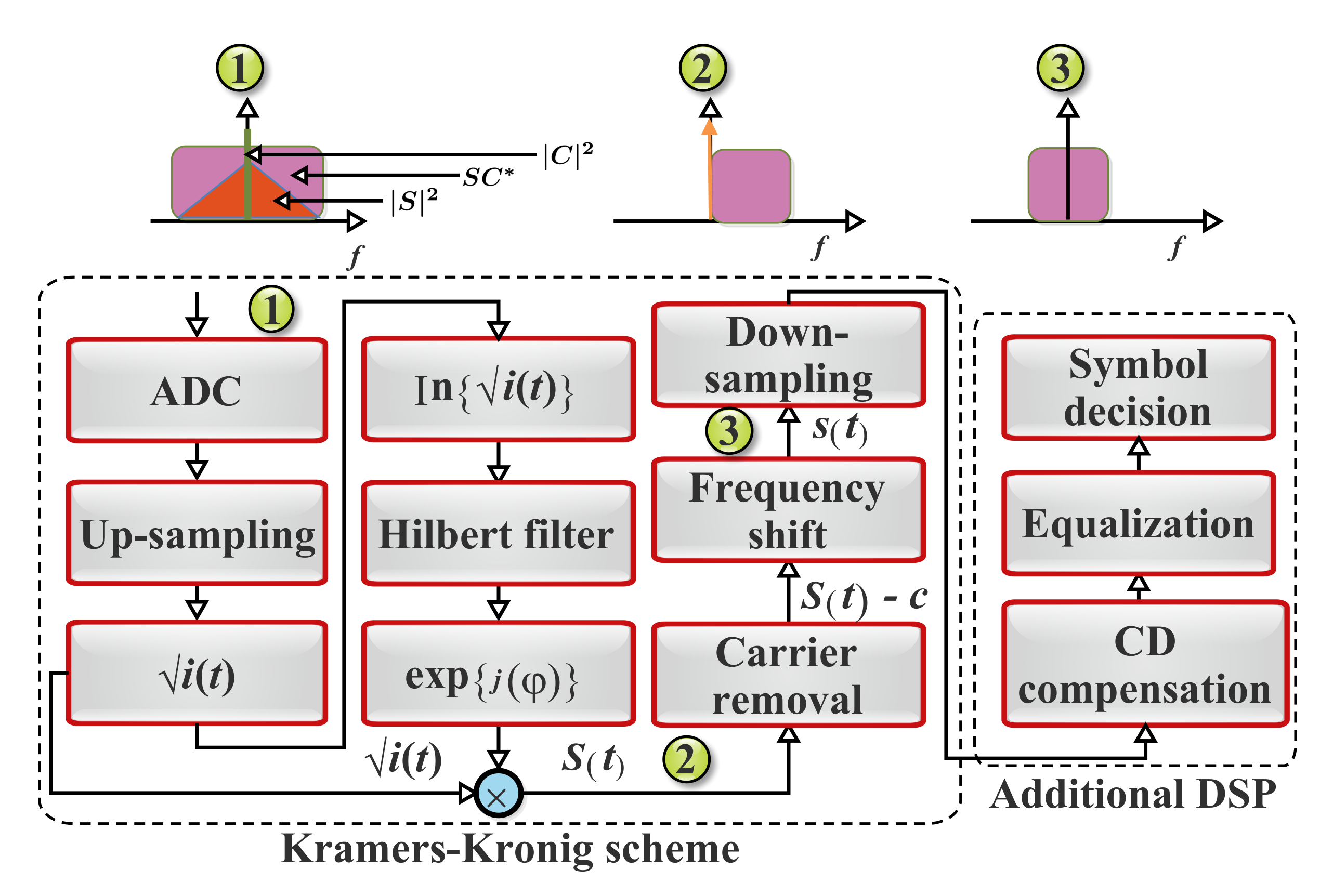
Moreover, the KK algorithm is comprehensively presented, and due attention is paid to the related effects of different factors such as chromatic dispersion, the optoelectronic frontend, and IQ imbalance on the KK scheme;
(vii)
A comprehensive tutorial on various approaches by which the conventional KK system challenges regarding the spectral broadening, high CSPR value, and associated additional sensitivity penalty can be attended to considering factors such as the system complexity and latency is presented;
(viii)
Apart from different potential systems for 100 G and beyond applications that have been considered in the other review papers, we also present different SCOH-based experimental demonstrations that are capable of supporting high-speed short- and medium-reach use cases; Furthermore, an overview of recent research and development efforts on the enabling technologies to support 100 Gb/s and beyond (Tb/s) per wavelength is presented;
(ix)
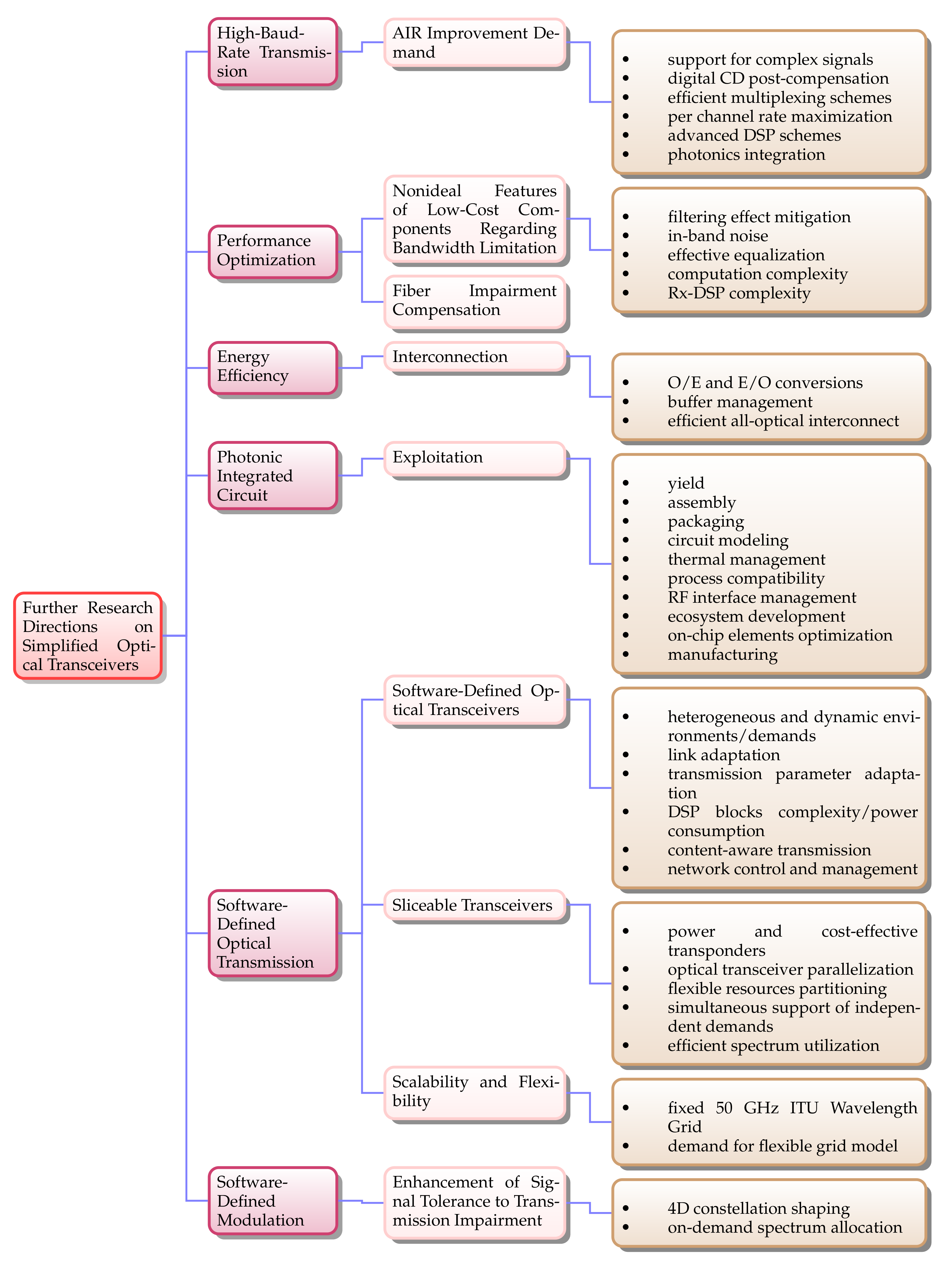
Additionally, we address further research directions and future optical network considerations for performance enhancement. In this context, advancement towards high-baud-rate transmission is presented, and the photonic integrated circuit (PIC) exploitation for low-cost, low-power consumption, and low-footprint schemes is comprehensively discussed. We highlight the need for tremendous synergy between photonic technologies and the software-defined networking (SDN) programmability to facilitate the functionalities of flexible transceiver systems that will be able to support the content-aware future transmission systems. An in-depth discussion on how the synergy can facilitate advanced functionalities and ensure full exploitation of photonic technology’s potentialities and available resources is presented.

1.3. Organization

The remainder of this paper is organized as follows. Section 2 discusses the need for per-wavelength AIR enhancement based on simplified systems for future networks and use cases. A comprehensive analysis of the associated short-reach system features and enabling technologies is given in Section 3. In Section 4, an overview of SSB signal generation and SSBN mitigation techniques is presented. Moreover, in Section 5, we discuss the principles of the KK algorithm regarding both the conventional and modified KK schemes. Section 6 focuses on the transceiver architectures and their related features. Moreover, we present different concerted efforts towards simplified transceiver architectures in Section 7. Furthermore, Section 8 focuses on the associated concepts, implementations, technical challenges, and potential solutions of various prospective SCOH transceiver structures. In Section 9, a comprehensive review of the polarization recovery schemes and Stokes space field recovery techniques is presented. Section 10 presents some key experimental implementations of the SV-DD- and KK-based schemes. It also offers a fair comparison between both schemes. In addition, Section 11 addresses further research directions and future optical network considerations for simplified transceiver architectures. Furthermore, concluding comments are given in Section 12.

2. Beyond 100 Gb/S Era

This section presents the need for per-wavelength AIR enhancement based on simplified transmission systems.

2.1. The Need for per Wavelength AIR Enhancement

The 100 G standards for short-reach optical transceivers are defined by the IEEE 802.3. The 100 GBase long-range (LR4) defines the optical interface for four wavelengths at about 1310 nm based on a channel spacing of 4.5 nm with an achievable transmission range of 10 km. The 100 GBase-ER4 can operate over a 40 km range [36,62]. The 100 G Ethernet local area network (LAN) interface standardization prompts the need for the enhancement of the per-wavelength AIR of the short-reach systems to 100 Gb/s and beyond. This is an effort to support and meet the growing increase in Internet traffic [9,24]. For instance, 100 Gb/s Ethernet frames’ transmission over 2 to 10 km SMF has been standardized as 100 GBASE-LR4 in the IEEE 802.3ba. In this context, four colors in the 1300 nm band are employed on a LAN-WDM grid with a 4.5 nm channel spacing and with individual channels supporting 25 Gb/s of intensity-modulated data. Besides the LR4 standard, 100 GBASE-SR4 offers specifications to support Ethernet frames over ∼100 m of multimode fiber. This is based on the employment of four fiber lanes with each of the lanes delivering 25 Gb/s in the 850 nm window. Furthermore, with respect to the IEEE 802.3 ba standard, there are a number of commercial 100 G transceivers on the market. These transceiver modules are C form factor pluggable (CFP) such as CFP and CFP2, which are the industry standard MSA form factors that are designed for optical communication applications. They are intended to support 40/100 G and are compliant with the 40 and 100 GBase IEEE 802.3ae standards [63]. There are some efforts toward 400 G and beyond (1 Tb/s) Ethernet. For instance, CFP8, which is a form factor being specified by the CFP MSA for 400 G Ethernet solutions, has been presented. The two 400 G transceivers designed for this purpose are CFP8-FR8 and CFP8-LR8 [64,65].

2.2. Why the Need for a Simplified System?

The aforementioned 100 G Ethernet standard and the existing commercial products are based on either WDM or spatial multiplexing to realize the aggregate bit rate. However, there is a growing consensus that the realization of the anticipated 400 Gb/s and 1 Tb/s depends mainly on the employment of inexpensive, power-efficient, and low-footprint components in the achievement of 100 Gb/s on a single wavelength. The WDM approach in which lower rates such as 25 or 50 Gb/s are multiplexed in the wavelength is challenging due to the required large number of laser sources. For instance, the realization of 400 Gb/s and 1 Tb/s using 8 × 50 Gb/s and 20 × 50 Gb/s, respectively, based on the required amount of lasers, hinders the overall performance of the transceiver. Furthermore, the additional stringent requirements being imposed on the laser wavelength stability and the transceiver packaging both optically and thermally are more demanding. Similarly, regarding the spatial multiplexing approach in which multiple fiber lanes per cable are employed, there will be some challenges concerning packaging, as well as end-to-end interfacing between the parallel fiber lanes and the transceiver. To minimize the required amount of laser, it is advisable to employ ( 4 × 100 ) Gb/s based on four colors for the realization of 400 Gb/s solutions. In this, each wavelength will be supporting 100 Gb/s, and all wavelengths can be launched on a coarse WDM (CWDM) grid (20 nm spacing) or LAN-WDM (4.5 nm spacing) [63].
Furthermore, for the system scalability from 400 Gb/s to 1 Tb/s, ten lasers will be required to be packaged in either a CFP, CFP2, or CFP4 form factor, and this is relatively challenging. On a CWDM grid, it is impractical to fit ten lasers in the O-band. Consequently, an alternative solution is to employ a LAN-WDM grid. Another factor to be considered in this situation is that the development of uncooled transmitters will be very demanding as the lasers normally have a 0.1 nm / C wavelength temperature coefficient. Therefore, a scheme that helps minimize the required number of colors while enhancing the bit rate per wavelength is a promising solution for attending to the system demand. The scheme can exploit additional DoFs to double the realizable bit rate per wavelength. One such viable solution is the polarization division multiplexing (PDM) schemes [63].

2.3. Ethernet Standards and Optical Transceiver Applications

As previously mentioned, owing to innovative applications such as virtual reality, machine-to-machine communication, online gaming, and other time-sensitive services that will be supported by the 5G and beyond network, there has been a growing need to improve the bandwidth in the data center industry. To achieve the system requirements, there has been a notable transition to new categories of fiber connectivity protocols and media. Furthermore, as a data center normally supports heterogeneous applications and services that co-exist at varying speeds and requirements, it is important to understand existing Ethernet standards and related transceiver types. Proper fiber optic infrastructure identification for different network configurations is of utmost importance. In this subsection, we focus on different transceivers (10/25/40/100/400 GbE) and present a clear guide that can facilitate the selection of the appropriate fiber optic infrastructure for different network configurations.

2.3.1. Optical Transceivers and the Related Ethernet Standards

Some classifications regarding the link reach, transceiver form factor, interface connector type, fiber type, and speed have to be taken into consideration when choosing the most suitable transceiver. For short-range (SR) applications (∼500 m), interfaces such as SFP+, SFP28, QSFP+, QSFP28, and QSFP-DD are the most widely used. Similarly, CFP, CXP, and CPAK are preferred interfaces for long-range (LR) and high-speed applications [66,67]. Depending on the application, both single-mode fiber (SMF) and multimode fiber (MMF) can be used for data transmission using the aforementioned transceivers. For instance, they can be used for certain SR 40 G and 100 G applications. However, SMF with Dense-WDM is normally employed in the LR transmission. This results in higher data rates and longer ranges (∼40 km). It should be noted that 400 G deployment in the hyperscale data centers will be largely supported by quad small form factor pluggable-double-density (QSFP-DD) transceivers. Table 1 summarizes key parameters for the different transceivers with a range of specifications for various applications [66].

2.3.2. Ethernet Standards and Optical Transceiver Applications

The legacy Common Public Radio Interface (CPRI) and Open Base Station Standard Initiative (OBSAI) lines mainly focus on 3G/4G mobile fronthaul (FH) networks. Moreover, the legacy CPRI/OBSAI line has standard temperature modules (0 to 70 ℃) that can be used in conventional telecom environments. Industrial temperature (−45 to 85 ℃) modules can also be deployed in harsh environments such as unheated outdoor cabinets and mobile BS towers. In the 3G/4G networks, high networking speeds are not required between the remote radio unit (RRU) and the baseband unit (BBU) compared with 5G mobile network configurations. Consequently, 10G FH SFP+ optical transceivers can be used to satisfy the transmission requirements. Furthermore, based on the base station (BS) manufacturer standard preference, these transceivers can be coded either for the CPRI or OBSAI bit rates. CPRI Options 2 to 8 with line bit rates that range from 1228.8 Mbps to 10.138 Gbps and OBSAI RP3 × 2 to RP3 × 8 with rates of 1.536 Gbps to 6.144 Gbps can be employed to support 10G-FH.
Moreover, with the heterogeneous wireless network evolution, the demarcation point between the FH, midhaul (MH), and backhaul (BH) is becoming indistinct and thin. This imposes stringent requirements on mobile transport networks, demanding the redesign of the interfaces [1]. Therefore, it is imperative to develop an innovative transport network architecture, capable of supporting the multiple hauls simultaneously, as depicted in Figure 1. In this regard, the transport network should be able to support heterogeneous transmission media such as high-capacity copper, optical (e.g., wireless/fiber-based), and wireless (e.g., mmWave/THz) for the network elements’ interconnection. Furthermore, they should be able to converge to support different FH link solutions such as the existing protocols (CPRI) and 5G-specific protocols (eCPRI, Next-Generation Fronthaul Interfaces (NGFI)), envisaged 6G-specific protocols, latency-sensitive Ethernet, Ethernet-based backhaul, and generic packet-based solutions [68]. This results in the idea of an integrated transport network known as the “any-haul or X-haul” for all-generation (X-G) coexistence (3G/4G/5G/6G) [69].
The need to support X-haul in the 5G and beyond networks imposes new demands on optical transceivers. In this context, there is a growing need for high-rate optical transceivers as a higher cell site density is required. Therefore, as summarized in Table 2, 25 G/100 G optical transceivers are required for the 5G optical FH network to support massive MIMO, while carrier-grade 100 G/200 G/400 G transceivers are required for the MH/BH. In view of this, eCPRI is a better solution compared with CPRI/OBSAI [70]. In Section 3.3, we present various enabling technologies for the optical transceivers to support 5G and beyond applications.

3. Short-Reach Systems Classification and Enabling Technologies

This section discusses the short-reach systems with the main focus on the DCNs. The related short-reach system features such as classifications, potential modulation formats, advanced optoelectronic devices, requirements, and challenges that necessitate novel transceiver architectures and DSP techniques are comprehensively analyzed.

3.1. Short-Reach Systems’ Overview and Classification

This subsection focuses on the overview and classification of the short-reach systems. They can be grouped in line with the associated technological features and limiting factors. A typical optical communication scenario is illustrated in Figure 2.

3.1.1. Intra-Data Center or Server-to-Server Links

In a DCN, intra-data center or server-to-server links are the data links that connect one server to another and the racks together inside the DCN. These kinds of links are usually below 300 m, and they comprise the major amount of the DCIs. Currently, the links are dominated by the MMF due to the extremely cost-efficient vertical-cavity surface-emitting laser (VCSEL) transmitters’ employment. Since the links are mainly based on the MMF, the major limiting factor is the associated intermodal dispersion that severely limits the data rate per wavelength to below 40 Gb/s [35,42].

3.1.2. Inter-Data Center Links

Inter-data center links are usually below 20 km and are typically employed to connect one data center to another and ensure data exchange between multiple DCNs [35,42]. Furthermore, they are usually referred to as DCIs [42]. Unlike what is entailed in intra-data center links, inter-data center links exploit the standard SMF (SSMF). This is mainly owed to the length scale, which is too long for the MMF implementation. The employment of MMF for this length scale can bring about an intermodal dispersion. In contrast, the length scale is relatively short for an optical amplifier deployment. As a result, an essential parameter for system optimization is receiver sensitivity. Furthermore, it is noteworthy that advanced photodiodes such as high-bandwidth avalanche photodiodes (APDs) offer considerably better receiver sensitivity compared with the conventional PIN PD. Furthermore, with an increase in the chromatic dispersion effects in conjunction with the baud rate and distance, the direct detection scheme eliminates the signal phase information, making the system nonlinear. Consequently, the chromatic dispersion effects have to be attended to by exploiting innovative signaling and DSP techniques. O-band transmissions are also a means of addressing this issue. This is due to the chromatic dispersion that is minimized at that wavelength band for the SSMF [35].

3.1.3. Extended Reach Inter-Data Center, Access, and Metro Links

As these links can be between 20 km and 80 km, optical amplification can be employed in certain scenarios. In spite of this, direct detection receivers are still the preferred candidates for these applications when compared with the full CO-Rxs. Therefore, to enhance the bit rate, polarization-multiplexed direct detection configurations such as the SV-DD receivers have been receiving considerable attention. Alternatively, there are various intensive efforts towards enhancing the bit rate, as well as the transmission distance of O-band systems without the need for optical amplification. Due to the considerable advances in digital COH systems, full COH transceivers are becoming more economical, power efficient, and compact. In this regard, full COH transceivers are anticipated to be adopted for the extended reach inter-data center links [35]. In the following subsection, we focus on the DCNs and the related concepts.

3.2. Data Center Network Requirements and Challenges

A data center is a physical facility employed by different organizations to accommodate vital data and applications for the advancement in the information technology industry and economic transformation [72]. Moreover, the design of data centers is mainly contingent on several factors such as the storage resources and network of computing that facilitate the effective provision of the shared data and applications. Typically, DCNs are designed to support different applications and activities such as productivity applications, email, file sharing, artificial intelligence, big data, machine learning, customer relationship management, enterprise resource planning, communications, and collaboration services [73]. In this subsection, we present a comprehensive discussion of the DCN requirements and the associated challenges. Moreover, we proffer potential solutions to address the related challenges.

3.2.1. Resilience

Network resilience is one of the main concerns in DCNs. For example, optical interconnects that employ centralized architectures in which a single ultra-high-capacity optical switch is supporting a significant amount of servers are highly susceptible to single-point-of-failure issues. Consequently, robust architectures are required to address the issues. A notable way of attending to this is network redundancy. For instance, each network element (i.e., aggregate switch) can be connected to multiple core switches with multiple links. Apart from the fact that this approach can offer improved connectivity, it also ensures better resilience in the event of an interface or link failure [74].

3.2.2. Energy Consumption

The high economic impact of DCNs regarding energy efficiency has been attracting considerable attention. The required energy for an effective operation usually results in higher operational expenditure (OPEX) costs. For instance, it has been observed that DCNs consume about 10–20% of the entire information technology power of the sites [72,74]. Consequently, substantially energy-efficient interconnections are required for sustainable higher network traffic with relatively less energy consumption [74].

3.2.3. Traffic

It has been observed that the majority of network traffic processing is within the DCNs (intra-DCNs). This is mainly due to a large amount of hosted applications that are based on parallel programming frameworks. This setup demands significant interaction among the distributed storage and processing nodes for huge data management. This implies considerable communication requirements among the servers. The intra-DCNs’ traffic increase is also owed to the introduction of innovative high-performance server processors. The processors host interfaces that can support 10 Gb/s data rates. In addition, with the integration of different high-performance processing cores into a single processor, higher-bandwidth interfaces are needed for effective communication between those cores and other cores hosted on separate racks. DCN operators have been adopting 100 Gb/s Ethernet and beyond to meet the network demands [74].

3.2.4. Scalability

One of the major benefits of the existing DCNs is that they can efficiently scale to a fat-tree topology that is capable of interconnecting racks that host thousands of servers. This is facilitated by leveraging the resources and economies of scale of the Ethernet switches. In contrast, the majority of optical interconnects are based on centralized architectures, which causes significant scalability limitations. For instance, apart from the concerns about the associated cost of the devices, there are also related technical challenges that may hinder performance enhancement. Consequently, the means of achieving scalable optical interconnect schemes that are capable of hosting a huge number of servers in the DCN is of utmost importance to the operators [74].

3.2.5. Latency

As previously mentioned, DCNs have hundreds of thousands of servers that need to communicate with each other by means of low-latency and high-performance interconnection networks [74]. Furthermore, a considerable amount of computation and data storage is usually executed in DCNs [75]. Therefore, based on the associated supercomputing, as well as other delay-sensitive cloud applications/services, DCNs demand more stringent latency than the long-haul systems. Furthermore, short-reach systems normally experience small propagation delays and comprise fewer link components, which can incur relatively less signal delay. Consequently, for short-reach systems, the main element that incurs significant latency is the forward error correction (FEC). Typically, the FEC latency can be between 15 and 150 μ s , making it the key contributor to the total system latency. Based on this, complicated soft decision-FEC (SD-FEC) with iterative decoding methods is not usually considered as an effective option. Therefore, either a standard hard decision-FEC (HD-FEC) or other innovative low-latency codes are more applicable to the short-reach systems. It should be noted that the implementation will also impose more stringent requirements regarding the pre-FEC BER and receiver sensitivity [35].

3.3. Enabling Technologies for Short-Reach System

In this subsection, we present different potential modulation formats and advanced optoelectronic devices for the short-reach systems along with the associated requirements and challenges.

3.3.1. Potential Modulation Formats

This subsection briefly presents some advanced high-order modulation formats that can be exploited to considerably scale the transmission speed of short-reach systems.

Pulse Amplitude Modulation

The simplest high-order modulation format to achieve a higher bit rate with limited bandwidth components is pulse amplitude modulation (PAM). Compared to the non-return-to-zero on-off-keying (NRZ-OOK) format, information bits can be encoded on multiple optical amplitude levels such as PAM-M (e.g., PAM-4, PAM-8, or PAM-16). The NRZ modulation format is more tolerant of ISI compared to multilevel intensity signaling such as PAM-M [17,42]. Furthermore, it is noteworthy that when the level number doubles, the receiver sensitivity will be significantly reduced by a factor of four. Therefore, a higher optical signal-to-noise ratio (OSNR) is usually demanded by the higher-order PAM signals. Besides being more susceptible to channel impairments such as the chromatic dispersion, they demand DSP schemes that are more complex [36,42]. Furthermore, it is noteworthy that in view of the tradeoff between the achievable bit rate and system performance, PAM-4 is a more practical and promising alternative compared with higher-order PAM signals [35]. Therefore, regarding the implementation complexity and system performance, it has been considered as a more attractive format for short-reach applications [76]. Remarkably, PAM-4 has been adopted by the IEEE 400 GbE P802.3bs task force for the DCIs [35]. Furthermore, PAM-4 has been adopted by the 100 GBASE-KP4 for electrical backplane interconnects [16].

Carrierless Amplitude and Phase Modulation

Bell Laboratories proposed carrierless amplitude and phase (CAP) for asymmetric digital subscriber line (ADSL) applications in order to improve the transmission AIR by means of orthogonal multiplexing method [36,77]. It facilitates the quadrature amplitude modulation (QAM)-type signal generation with a relatively simpler implementation [35]. Unlike the QAM scheme where individual data streams are modulated, a digital filtering process is employed in CAP for the generation of quadrature signals without additional carriers. To achieve this, the CAP transmitter generates a QAM-like signal through the combination of the Hilbert pair of two filtered multilevel signals [16,36]. In this regard, the CAP system implementation is relatively simple. With the rapid advancement regarding the capability and the processing speed of integrated circuits, CAP modulation has been finding application in the IM-DD schemes and has been considered as one of the viable solutions for realizing optical transmission in the range beyond the usual capacity (i.e., over 100 Gb/s can be realized) with enhanced performance regarding the SE, complexity, and cost [77]. However, CAP is highly sensitive to nonflat channel frequency responses. Based on this, the ITU G.992.1 G.DMT (discrete multitone) has been adopted as the predominant standard. The DMT-based ITU-T G.992.1 expands the usable bandwidth of telephone lines [36].

Discrete Multitone Modulation

In a distributed radio access network (D-RAN) or centralized/cloud radio access network (C-RAN) where massive-MIMO techniques and CPRI/eCPRI interfaces are implemented, radio-over-fiber (RoF) schemes are normally employed for the transmission between the BBU and RRHs [1]. In this network, the RoF signal is usually impaired by the fiber link chromatic dispersion (when SMF is employed) or multimode dispersion (when MMF is employed). The multipath fading of the wireless link and imperfection of the BS components contribute to the signal impairment as well. One of the promising solutions to simultaneously attend to the fiber link dispersion and wireless link multipath fading effects is optical orthogonal frequency division multiplexing (OFDM) [78,79,80]. In this context, if the guard interval is sufficiently longer than the total delay spread caused by chromatic dispersion and maximum differential group delay, the impairment can be compensated using an optical OFDM. To achieve this, the employed cyclic prefix has to be longer than the total delay spread owing to dispersion and multipath spreading effects [78].
DMT is a category of the OFDM scheme, and it is known as DD-OFDM. In DMT, the frequency spectrum is divided into orthogonally modulated subcarriers. Then, the input data sequence are electrically encoded onto each subcarrier. Furthermore, being a multicarrier modulation scheme, it presents attractive features such as flexible multilevel coding, high SE, and high tolerance to channel impairments. As previously mentioned, DMT is being implemented in the ITU-T ADSL standard, and it was later adopted for the ITU-T very-high-speed DSL 2 (VDSL2) standard. Furthermore, it has been attracting considerable attention for the low-cost and bandwidth-limited short-reach communication applications. This is because of its inherent flexibility to shape the transmitted signal’s frequency spectrum [42,76]. Nonetheless, as other multicarrier schemes such as OFDM, DMT presents a high peak-to-average power ratio (PAPR) issue. The high PAPR issue usually has a considerable influence on the DMT’s tolerance to the relative intensity noise (RIN), as well as the ADC and DAC resolution requirements [42]. Furthermore, the efficiency of ADC and DAC with a limited effective number of bits (ENoB) can be optimized by clipping the related signal waveform. The employed optical modulators can be driven in the nonlinear region. This is to ensure a high modulation index and, consequently, that the achievable system signal-to-noise ratio (SNR) is maximized. It is noteworthy that this approach is essential when the SNR is the limiting factor for highly spectrally efficient signals. Nevertheless, the approach presents an issue regarding the enhanced system nonlinearities. This occurs with the interplay between the transmitter-induced nonlinearities and the fiber chromatic dispersion, as well as the nonlinear square law detection at the receiver. This issue can be mitigated with the use of nonlinear equalizers at the receiver [42].

Multicarrier Entropy Loading

In addition, with a number of advanced optical modulations that have been presented, the capacity of optical transmission systems has been pushed towards the limit. Consequently, in an attempt to squeeze out the last few bits from bandwidth-limited optical channels, multicarrier entropy loading (EL) has been proposed. EL is based on probabilistic constellation shaping (PCS) and goes beyond bit loading (BL) through continuous source entropy adaptation. This can significantly help enhance the achievable information rate. In this context, EL is an effective solution for realizing an optimum AIR in bandwidth-limited channels under frequency-selective fading. This makes it a promising scheme for short-reach interconnects [81].

Optical Single-Sideband Modulation

Another attractive modulation scheme that has been gaining significant recognition for different applications is the single-sideband (SSB) modulation. For instance, the SSB-DMT, SSB-PAM4, and SSB-CAP schemes have been gaining significant attention [53,82,83,84,85]. This is mainly due to the notable offered advantages such as the improved SE and significant resistance to chromatic dispersion because of the EDC capability [55,56]. Comprehensive information on the SSB signal generation and associated concepts is given in Section 4.

3.3.2. Advanced Optoelectronic Devices for High-Speed DCIs

Apart from the advanced formats that have been discussed so far, there are different research efforts on optoelectronic devices and components to support high-speed DCIs. This subsection focuses on different devices for short-reach transmission systems.

Vertical-Cavity Surface-Emitting Lasers

Cost-effective support of the unprecedented data traffic demands the use of inexpensive laser diodes at the transmitter. The laser should be able to offer sufficient output power and high modulation bandwidths, and emit in the nearinfrared [86]. Directly modulated VCSELs have gained significant attention in high-speed applications because of the associated benefits such as the small footprint, energy efficiency, and cost effectiveness [87,88]. For instance, gallium arsenide (GaAs) 850 nm multimode (MM) VCSELs in conjunction with MMF are widely employed in the commercial short-reach intra-DCI. However, one of the main performance limitations of this implementation is the modal dispersion, which is instigated by the differential modal delay (DMD) in the MMF [42]. The modal dispersion effect can be mitigated by employing a single-mode or few-mode operation. Based on this, SMF deployment will be a promising option to support the evolving hyperscale DCNs. Similarly, the adoption of single-mode (SM) VCSEL-based technologies that are capable of mitigating the chromatic dispersion effects and supporting spectrally efficient transmissions over an extended reach are also an attractive option [76,89,90]. Nevertheless, the major weaknesses of single-mode VCSELs are that they usually have limited output power and demand further complex optical alignment. In order to prevent the high-order transverse modes’ lasing and achieve single-/quasi-mode lasing, the aperture size can be minimized by means of oxidation or through the integration of a mode filter that is generated through a surface relief [42]. Furthermore, VCSELs emitting at 980 nm, 1060 nm, and 1100 nm with a negligible increase in fabrication complexities and significantly high-modulation bandwidths have been studied in the upper limit of GaAs technology [42,89,90].
Moreover, considerable efforts have been presented on high-speed VCSELs for the 1.3 μ m and 1.55 μ m wavebands to extend the transmission range [86,88]. In this context, several device models such as nitrogen-containing quantum wells (QWs), wafer fusion, and buried tunnel junction (BTJ) have been attracting research attention in the 1.3 μ m waveband. On the other hand, for 1.55 μ m, only BTJ VCSELs in which a short-cavity design is exploited offer exceptional performance. An instance of such a design is based on the indium gallium aluminum arsenide (InGaAlAs) material. The associated optical, electrical, and thermal design of such devices and the relative design improvements were presented in [86].
Furthermore, InP-based VCSELs are capable of emitting at relatively longer wavelengths such as 1.3 μ m and 1.55 μ m. They have been attracting considerable attention owing to the associated lower losses and lesser power consumption. For instance, single-mode 1.5- μ m VCSELs that are InP based with two dielectric distributed Bragg reflectors (DBRs) and a 1.5- λ -long semiconductor cavity have been demonstrated [91]. The configuration offers superior dynamic characteristics and does not require FEC, DSP, or any equalization.

Directly Modulated Laser

A directly modulated laser (DML) typically generates high output power and has been considered to be a more power- and cost-efficient approach compared with the external modulation solutions. This is owed to the fact that the laser bias current is driven directly by the modulated signal. Furthermore, due to their compactness, they can be easily integrated with other devices. Based on the associated features, DMLs have been considered as attractive solutions for cost-sensitive DCNs and access networks. Nevertheless, the DML capability for high-speed data links is hindered by the limited modulation bandwidth. To attend to the drawback, different viable techniques can be adopted along with advanced modulation formats and DSP. For instance, the DML modulation bandwidth can be enhanced through the exploitation of innovative design and techniques such as multisection laser design [92], multiple quantum well (MQW) laser design [42,92], and injection locking [42]. Another limiting factor for the DML-based system is the spectrum broadening, which is mainly due to the inherent chirp effect. Several techniques both in the optical and digital domains can be used to address the chirp effect [42,93].

Mach–Zehnder Modulator

The Mach–Zehnder modulator (MZM) has been widely employed in IM-DD optical communications for external modulation. It operates through the combination of two-phase modulators within a Mach–Zehnder interferometer structure to accomplish intensity modulation. Furthermore, for effective support of high-speed communications using advanced modulation formats, significant efforts have been made regarding the realization of small-sized, but high-performance MZMs. It is noteworthy that commercial MZMs are usually made from lithium niobite (LiNbO 3 ) and are capable of supporting high-capacity transmissions [94]. Nevertheless, they are typically packaged into bulky modules that are not only expensive, but also energy-intensive. Therefore, their application for client-side optical interfaces such as pluggable optical transceivers is hindered. Based on this, they might not be able to meet the usual growing requirement in the optical communication links [42,95]. These challenges can be addressed by the employment of monolithically integrated LiNbO 3 electro-optic modulators [95]. Energy-efficient integrated nanophotonic LiNbO 3 MZMs with a high bandwidth can also be employed. Likewise, MZMs that are based on InP can be produced at a low cost and be monolithically integrated into a small size [42,94]. For instance, a distributed feedback (DFB) laser that is based on InP can be monolithically integrated with the MZM. Similarly, another good example is the MZM laser that is based on InP being integrated with a capacitance-loaded traveling-wave electrode (CL-TWE). Additionally, SiP-based MZMs fabricated with wafer-scale technology are also viable solutions [94]. In this context, there have been intensive research efforts on multi-electrode MZMs (ME-MZMs) [96,97] and SiP-based traveling-wave MZMs (TW-MZMs) [98]. It is noteworthy that MZMs based on SiP and InP are now in the industrial development stage. MZMs based on silicon-organic hybrid (SOH) platforms have been presenting attractive features to support high data rates [99].

Double-Sided Electro-Absorption Modulated Lasers

Electro-absorption modulated lasers (EMLs) are based on a well-developed InP technology and have been extensively employed for short-reach links because of the associated advantages such as the high bandwidth, small form factor, and large extinction ratio [100]. Typically, an EML has just one modulated output, and the other output is normally employed for monitoring. In a double-sided EML (DS-EML), two EAMs are integrated on both sides of the laser. Consequently, two independent optical modulated signals can be offered at the same wavelength by a DS-EML. It is noteworthy that it is relatively challenging to generate polarization division multiplexed signals by employing two discrete EMLs. This is owed to the relative wavelength drifting. In this regard, a DS-EML is an ideal solution for polarization division multiplexed signal generation due to the two offered independent modulated outputs at the same wavelength [35,100].

Electro-Absorption Modulator Integrated with a Distributed Feedback Laser

In the commercial 10G and 25 G transceiver applications, the distributed feedback laser with electro-absorption modulator EAM (EA-DFB) has been widely employed [101]. Compared with the DML, the EA-DFB lasers offer notable advantages such as an improved extinction ratio, better modulation linearity, and enhanced bandwidth. With respect to the external MZM, it has a smaller size and requires a lower driving voltage at a lower cost, making it an attractive candidate for future high-speed applications. Moreover, another promising and advanced device is the distributed feedback laser that is monolithically integrated with a traveling-wave EAM (DFB-TWEAM). Apart from the high linearity of its phase response, the DFB-TWEAM device has a broad bandwidth that is capable of supporting several high-speed transmissions [42,102].
In general, short-reach transmission based on PAM-4 or -8, with either separated or integrated modulators and lasers, can support 100 Gb/s per lane. It should be noted that a simple IM-DD-based implementation with a low form factor and low-cost transmitters such as DMLs or EMLs is a promising technology for effective support of the future inter-DCI applications compared with an external modulation in which an MZM is employed. Nevertheless, the DMLs’ or EMLs’ system performances are limited by factors such as the modulation bandwidth and the electro-optical components’ nonlinear impairments for the modulation and detection of the signal. As previously mentioned, there are different approaches that are based on advanced DSP that can be exploited to mitigate the limitations [103].

Semiconductor Optical Amplifier-PIN/Transimpedance Amplifier Receiver

The achievement of a target BER in higher bit rate systems demands a higher SNR. This brings about a reduction in receiver sensitivity. To realize a high-power budget or receiver sensitivity, the employment of optical pre-amplification is essential. This can be achieved by employing erbium-doped fiber amplifiers (EDFAs). However, the EDFA implementation results in relatively higher costs and larger footprints, making it inappropriate for short-reach applications. To address this, a monolithic integrated SOA-PIN/transimpedance amplifier (TIA) receiver can be employed. Nonetheless, it operates only in the TE polarization. Furthermore, a receiver-based integrated semiconductor optical amplifier (SOA)-PIN chip that has low-polarization-dependent gain (PDG) can also be employed. The SOA-PIN chip exploits a buried heterostructure and a deep ridge evanescent PIN PD supported on a semi-insulating InP substrate [35].

High-Bandwidth APD Receiver

Compared with the PIN diode, an APD has a much higher responsivity. Based on this, it is an attractive device that can help achieve high receiver sensitivity and low-cost and long-reach transmission. For instance, a high-bandwidth Ge/Si APD can be employed. It is a promising device for future high-speed applications due to its ease of integration with other SiP devices [35].

Optoelectronic Oscillator

Oscillators are normally used for the conversion of energy from a continuous source to a signal that varies periodically. A wide range of electromagnetic, mechanical, and atomic oscillators offers a varied range in the approximation to the achievement of an ideal harmonic oscillator. It is noteworthy that for a given oscillator, the accuracy of this approximation is determined by the degree of output signal stability and spectral purity. This is primarily contingent on the oscillator’s energy storage capability, which is based on the resistive loss (normally frequency-dependent) of its different elements [104]. Furthermore, an extensively used oscillator is the electronic oscillator. An electronic oscillator can either be based on a vacuum tube or solid-state technology. Both solutions are not only noisy, but lack sufficient stability for applications that demand very high stability and spectral purity. This performance limitation is due to the ohmic and dispersive losses of the various elements of the oscillator. In light of this, to address the associated challenges, different efforts have been presented by combining a high-quality (Q)-factor resonator with the electronic oscillator. The Q represents a figure of merit for the resonator. Furthermore, different high-Q resonators such as electromagnetic, mechanical, and acoustic can be employed for electronic oscillator stabilization, resulting in hybrid oscillators known as electromagnetic, electromechanical, or electro-acoustic. It should be noted that the resonator selection is normally determined by a range of factors; however, for the maximum achievable Q at room temperatures, the crystal quartz (mechanical) resonator is the best choice for the electronic oscillator stabilization. Nonetheless, owing to their limited high-Q resonant modes at low frequencies (∼10 to 100 MHz), crystal quartz resonators offer a restricted range of frequency tenability, making them unsuitable for the direct generation of high-frequency signals. This issue can be addressed by the implementation of an optoelectronic oscillator (OEO) [104,105].

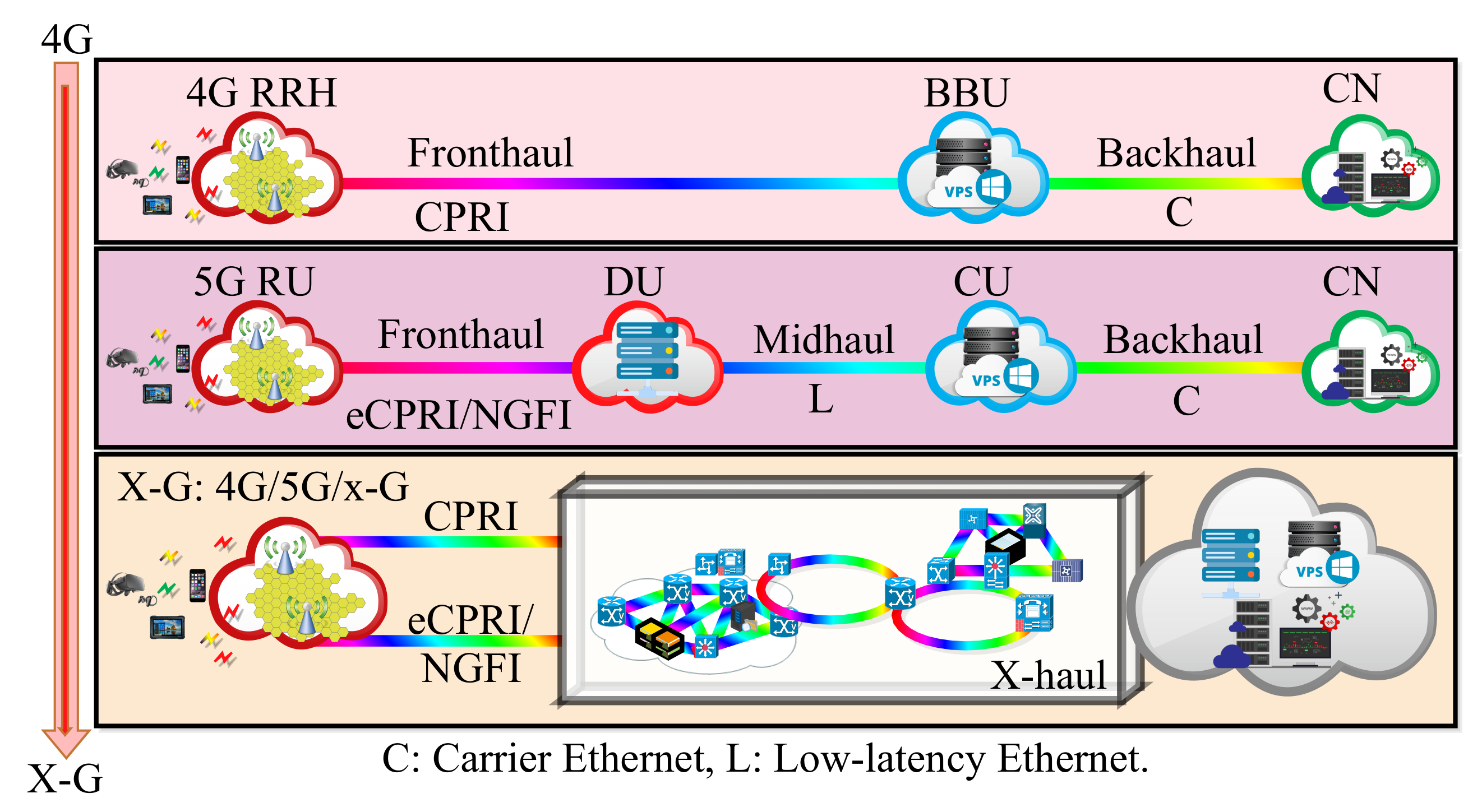
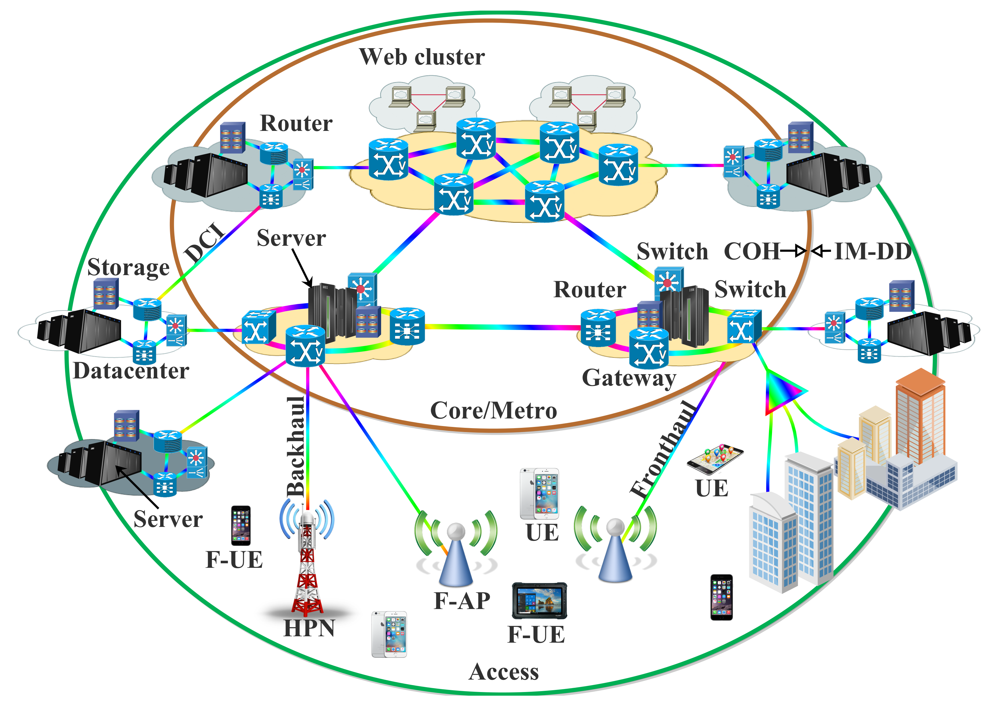
3.3.3. Optoelectronic Devices and Modulation Formats’ Applications in the 5G Network

To improve the network performance, innovative functional splits and related standards have been introduced in 5G. In this context, new quality-of-service requirements are imposed on optical transport. Based on the system requirements, several advanced transceiver configurations and modulation formats can be employed for different 5G use cases. Furthermore, various transceiver components can be selected based on the network demand. Table 3 summarizes some of the presented modulation formats and advanced optoelectronic devices for 5G applications considering optical transceivers discussed in Section 2.3.2. In this regard, we focus on different transceiver configurations for 5G X-haul (FH, MH, and BH). The related wavelength and the achievable transmission distance are considered.

3.3.4. Requirements and Challenges

This part presents a number of system requirements and the specific constraints that make the application of digital conventional COH systems inappropriate for short-reach systems. Consequently, the associated system requirements prompt further research directions on novel transceiver architectures and DSP techniques. This will be discussed in this subsection.

Cost

The short-reach transceiver applications require a low cost, so high-performance devices such as thermoelectric cooling (TEC), LiNbO 3 external modulators, and low-linewidth external cavity lasers (ECL) are unattractive. It is noteworthy that the implementation of LOs and full CO-Rxs is undesirable. On the other hand, most of the short-reach transceivers usually comprise components such as DMLs, low-bandwidth PIN, VCSELs, and EAMs. Direct-detection-based schemes with simplified DSP are the more promising solutions for the short-reach systems compared with the COH schemes and their typical advanced DSP algorithms. Furthermore, since thermoelectric cooling and wavelength locking mechanisms are not required, a so-called coarse-WDM is used where the channel spacing is larger than the standard 50 GHz ITU grids [35].

Form Factor

In general, small form factors are very essential to the majority of optical transceivers. However, the demanded form factor by the short-reach applications such as DCNs is even more stringent. This is mainly due to the fact that the underlying form factors have significant effects on the port number and density, as well as the rack size to support the ports. These parameters determine the size of the DCN as a whole and the required cooling system. Therefore, the form factor plays a pivotal role in total energy consumption/usage by the system [35].

Other Challenges of Short-Reach Systems

As previously mentioned, short-reach systems demand low-cost components. However, these kinds of components usually offer imperfect results that consequently bring about the initiation of additional transmission impairments that are mainly peculiar to the short-reach systems. For instance, when a DML is directly modulated, a signal chirp will be generated. Components such as transimpedance amplifiers (TIAs), EAMs, and PDs also generate additional nonlinear distortions. The low-pass filtering effect that is owed to the insufficient bandwidth of different components is another typical impairment of the short-reach systems. The RIN of the laser source and the finite extinction ratios of the EAM degrade the SNR, and subsequently, the link power budget margins are reduced. Moreover, equalization of linear transmission impairments such as polarization mode dispersion (PMD) and chromatic dispersion is really challenging using direct detection with non-negative signaling. This is owed to the received signal spectrum, which cannot be simply multiplied by the inverse of the PMD/CD transfer function [17,35].

4. SSB Signal Generation and SSBN Mitigation Techniques

This section presents different techniques that can be adopted for carrier and SSB signal generation at the transmitter. The associated SSBN mitigation schemes at the receiver are considered.

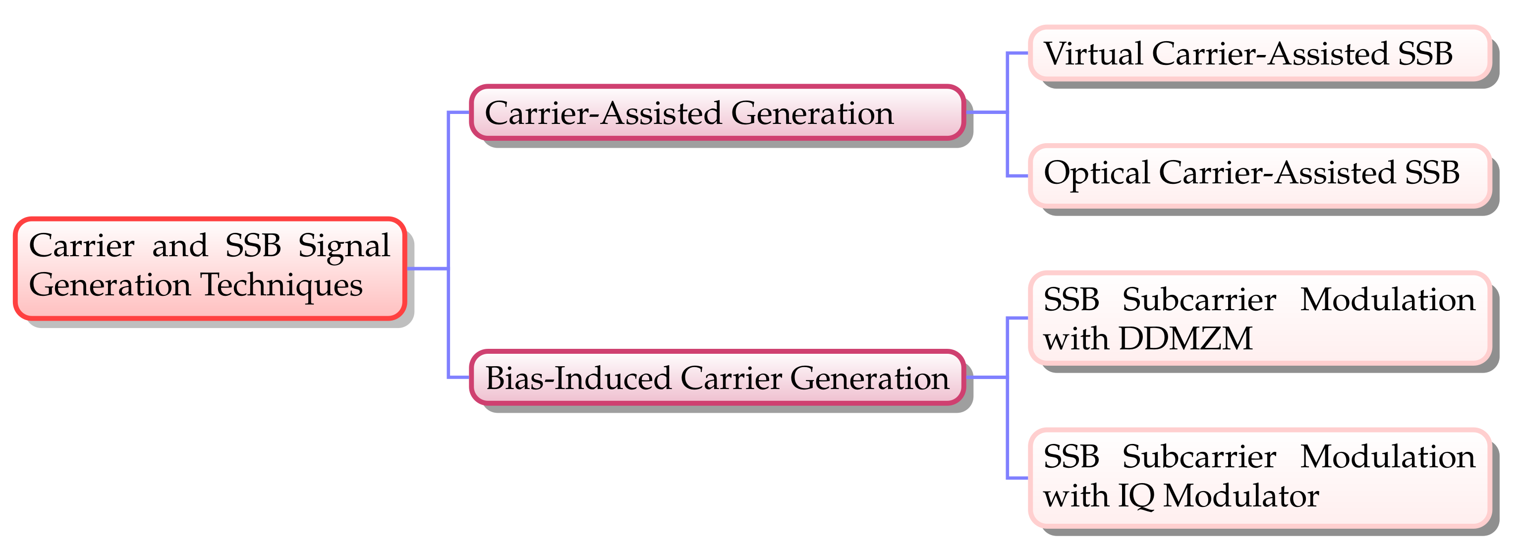
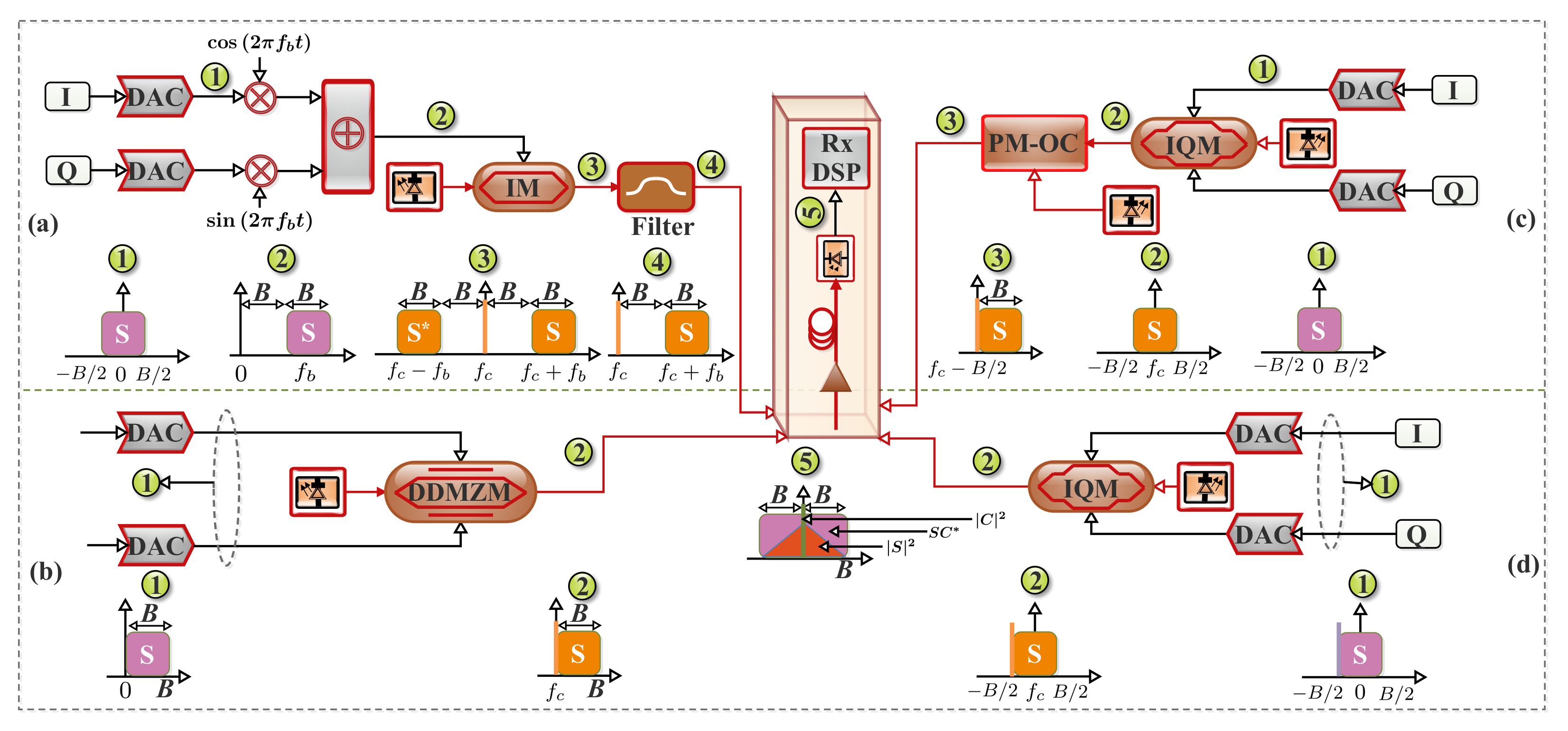
4.1. Carrier and SSB Signal-Generation Techniques

In this subsection, different means of generating SSB signals are discussed. In this context, the four extensively employed methods are considered. As illustrated in Figure 3, they are classified into two fundamental groups based on the adopted generation approach, which can be a bias-induced or carrier-assisted scheme. The considered SSB signal-generation schemes and the associated spectra are depicted in Figure 4.

4.1.1. Bias-Induced Carrier Generation Scheme

The bias-induced carrier generation scheme is based on the manner in which the I Q M or the dual-drive Mach–Zehnder modulator (DDMZM) is biased in order to generate the carrier.

SSB Subcarrier Modulation with the IQ Modulator

This approach is based on the employment of an optical SSB filter to remove one of the two sidebands of the DSB signal at the transmitter end [56]. In this scheme, both SSB Nyquist baseband signals are upconverted to a subcarrier frequency ( f s c ) of B / 2 by multiplexing with exp j 2 π ( B B 2 2 ) t . Instead of the null point, the I Q M can be biased either above or below the null point for an optical carrier to be induced. Therefore, an intensity modulator and an optical filter can be used to generate an optical SSB signal as shown in Figure 4a. Based on the IQ modulator transfer function, the SSB subcarrier modulation output when an IQM is employed can be expressed as [55,56]:
E o u t ( t ) = E i n ( t ) 2 cos π V π ( V I + V I b i a s ) + j cos π V π ( V Q + V Q b i a s ) ,
where E i n t and E o u t t represent the input and output optical field, respectively, V π is the half-voltage of the two electrodes, V I b i a s and V Q b i a s denote the DC bias voltage of two parallel phase modulators (PMs), and V I and V Q represent the two electrical signals to drive the modulators.
Moreover, Equation (1) can be rewritten as:
E o u t ( t ) = E i n ( t ) 2 cos π V π V I cos V I b i a s V π π sin π V π V I sin V I b i a s V π π + j cos π V π V Q cos V Q b i a s V π π sin π V π V Q sin V Q b i a s V π π .
In addition, if we assume a low-amplitude signal and set V I b i a s = V Q B i a s = V π V π 2 2 , Equation (1) can be rewritten as:
E o u t ( t ) = E i n ( t ) 2 sin π V π V I + j sin π V π V Q E i n ( t ) 2 π V π ( V I + j V Q ) TX s ,
where TX s denotes the output signal of the transmitter.
Based on Equation (3), the output signal of the transmitter in this SSB scheme can be expressed as [55,56]:
TX s = V I + j V Q = s ( t ) exp j 2 π ( B B 2 ) 2 ) t
where s ( t ) denotes the baseband signal at a bandwidth of B.
It is noteworthy that the in-phase component V I and quadrature component V Q are low-amplitude-value signals [83]. As a result, higher-order terms can be neglected. Therefore, if we set V I b i a s = V Q b i a s = V b i a s , the second-order Taylor series expansion of E o u t t can be expressed as:
E o u t ( t ) = E i n ( t ) 2 1 1 2 π V π V I 2 cos V b i a s V π π π V π V I sin V b i a s V π π + j 1 1 2 π V π V Q 2 cos V b i a s V π π π V π V Q sin V b i a s V π π
Furthermore, Equation (5) can be further simplified and rewritten as:
E out ( t ) = E i n ( t ) 2 ( 1 + j ) cos V b i a s V π π π V π ( V I + j V Q ) sin V b i a s V π π 1 2 π V π 2 ( V I 2 + j V Q 2 ) cos V b i a s V π π .
In general, the CSPR can be expressed as:
C S P R =   10 log 10 P c a r r i e r P s i g n a l
Based on Equation (7), the CSPR of SSB subcarrier modulation with the IQM can be deduced from Equation (6) as [55]:
C S P R S S B S C M I Q M = 10 log 10 ( 1 + j ) cos V b i a s V π π 2 π V π sin V b i a s V π π 2 s ( t ) 2 ¯ = 10 log 10 2 π V π 2 tan 2 V b i a s V π π s ( t ) 2 ¯
Although this method is the simplest solution, it requires a sharp optical filter to remove one of the two sidebands of the DSB signal. Therefore, apart from the extra expense that has to be incurred on the optical filter, when the spectrum gap between the SSB signal and carrier is narrow, the sideband that is meant to be eliminated will present some residuals, owing to the optical filter nonideal characteristics [53,55,56]. A guard band between the signal and the optical carrier is desirable to eliminate one of the sidebands. Furthermore, since the spectral gap bandwidth is the same as that of the signal, half of the electrical spectrum efficiency (ESE) is sacrificed in the process [40,56,107]. Based on this, one of the main weaknesses of this method is the additional bandwidth being occupied by the gap interval that would have been employed for data transmission. The additional bandwidth has a considerable effect on the required bandwidth of the ADC and DAC. On the other hand, it is also possible to employ converters with only a fourth of the bandwidth; however, this is at the expense of extra components [108].

SSB Subcarrier Modulation with the DDMZM

A DDMZM offers simpler bias control and a lower cost to generate the optical SSB signal compared to an optical I Q modulator. Figure 4b depicts an optical SSB signal generation with a DDMZM-based approach. In this, a digital SSB filter that depends on the Hilbert transformation is implemented at the transmitter. Consequently, the two driving signals of the DDMZM are a pair of Hilbert signals with a phase difference of π / 2 [55,56].
It should be noted that a DDMZM comprises two phase modulators that are driven by two independent electrical signals, which are V I and V Q with DC bias voltage V b i a s 1 and V b i a s 2 , respectively. If we set V b i a s 2 V b i a s 1 = V π / 2 and then assume an ideal extinction ratio (ER) condition and low-amplitude signal, the second-order Taylor series expansion of the DDMZM input–output relationship can be expressed as [83]:
E o u t ( t ) = E i n ( t ) 2 exp j π V π ( V 1 + V b i a s 1 ) + exp j π V π ( V 2 + V b i a s 2 ) = E i n ( t ) 2 exp j π V π V 1 + V b i a s 2 V π 2 + exp j π V π ( V 2 + V b i a s 2 )   E i n ( t ) 2 j 1 + j π V π V 1 π 2 V π 2 V 1 2 exp j π V π V b i a s 2 + 1 + j π V π V 2 π 2 V π 2 V 2 2 exp j π V π V b i a s 2 = E i n ( t ) 2 exp j π V π V b i a s 2 ( 1 j ) + π V π ( V 1 + j V 2 ) + π 2 V π 2 ( j V 1 2 V 2 2 )
In addition, this approach presents a tradeoff between robustness to chromatic dispersion and improved sensitivity [107]. It can be inferred from Equation (9) that the DDMZM-based implementation presents a large power penalty owing to the large direct current (DC) component. Due to this, the CSPR is more challenging for the required minimum-phase condition in the KK scheme. Consequently, the DDMZM is more appropriate for the SSB subcarrier modulation instead of the carrier-assisted SSB schemes [55].
Moreover, it is noteworthy that the optical modulation index (OMI) is generally used to measure the DDMZM’s performance, and it can be expressed as:
O M I = V R F r m s / V π
where V R F r m s denotes the root mean square (RMS) of the electrical input to the DDMZM.
The CSPR of SSB subcarrier modulation with the DDMZM can be deduced using Equations (7) and (9) as [55]:
C S P R S S B S C M D D M Z M = 10 log 10 1 j 2 π V π 2 s ( t ) 2 ¯ = 10 log 10 2 π V π 2 s ( t ) 2 ¯ = 10 log 10 2 π 2 O M I 2
It can be deduced from Equation (8) and Equation (11) that when a DDMZM is employed in the SSB subcarrier modulation, the related CSPR will be a function of the input electric signal and V π , while that of the IQM counterpart is not only a function of both aforementioned parameters, but also a function of the bias voltage, V b i a s .

4.1.2. Carrier-Assisted Generation Scheme

The carrier-assisted generation scheme implementation is presented in this subsection. It depends on whether the carrier tone to be appended to the signal spectrum is generated digitally or optically.

Optical Carrier-Assisted SSB

An optical I Q M driven by a pair of baseband signals can be employed for the SSB signal generation as illustrated in Figure 4c. Contrary to the implementations illustrated in Figure 4a where the I Q M can be biased either above or below the null point, in the optical carrier-assisted SSB approach, it is biased at the null point. This helps the optical carrier suppression [55]. Therefore, in this approach, a separate optical tone can be appended to the signal spectrum at a B / 2 frequency. Then, the polarization of the signal and the carrier are aligned at the transmitter side by means of a polarization-maintaining optical coupler (PM-OC) [56,109]. It should be noted that this implementation demands an optical frequency comb generation (OFCG) or an extra laser to generate the optical tone. However, this can bring about an increase in the cost and hardware complexity regarding the system implementation compared with the methods in Figure 4b,d [56].
Furthermore, with regard to the IQ modulator transfer function and the SSB modulation concepts, if an ideal extinction ratio and negligible insert loss are assumed, the output of the IQ modulator can be defined as:
E out ( t ) = 1 2 E i n ( t ) 1 2 exp j π V π ( V I + V I b i a s ) + 1 2 exp j π V π ( V I + V I b i a s ) + 1 2 E i n ( t ) 1 2 exp j π V π ( V Q + V Q b i a s ) + 1 2 exp j π V π ( V Q + V Q b i a s ) = 1 2 E i n ( t ) cos π V π ( V I + V I b i a s ) + j cos π V π ( V Q + V Q b i a s )
In the optical carrier-assisted SSB scheme, the optical SSB signal can be expressed as:
S out ( t ) =   E o u t ( t ) + A 1 exp j 2 π B 2 t exp ( j 2 π f c t )
where f c denotes the center frequency of the first laser (see Figure 4c) and A 1 represents the amplitude of the optical carrier that is generated by the second laser.
Correspondingly, the associated CSPR can be defined as:
C S P R O C A S S B I Q M = 10 log 10 A 1 2 E o u t ( t ) 2 ¯ = 10 log 10 4 V π 2 A 1 2 π 2 E i n ( t ) · s ( t ) 2 ¯

Virtual Carrier-Assisted SSB

Another promising and viable approach for generating an SSB signal is based on appending and copropagating a digital RF tone that serves as a virtual carrier in conjunction with the signal at the transmitter [53,56]. As the previously discussed scheme, this approach employs one I Q M and two DACs. As illustrated in Figure 4d, to suppress the optical carrier, the I Q M is biased at the null point as the approach in Figure 4c.
In this scheme, the output signal of the transmitter in this SSB scheme can be expressed as [55]:
TX s = s ( t ) + A exp j 2 π ( B B 2 ) 2 ) t
Furthermore, in the virtual carrier-assisted SSB scheme, the optical SSB signal can be expressed as:
E out ( t ) =   E i n ( t ) 2 π V π s ( t ) + A 2 exp j 2 π B 2 t exp ( j 2 π f c t )
where A 2 represents the amplitude of the virtual carrier that is generated by the second laser.
The associated CSPR can be defined as [56]:
C S P R V C A S S B I Q M =   10 log 10 A 2 2 s ( t ) 2 ¯
A close look at Equations (14) and (17) reveals that parameters such as the optical carrier power, input laser power, signal power, and V π can influence C S P R O C A S S B I Q M , while factors such as the optical carrier power and signal power influence C S P R V C A S S B I Q M . Furthermore, compared with the method shown in Figure 4b, dynamic CSPR adjustment can be realized easily by adjusting the digital tone amplitude in the virtual carrier-assisted system [56]. In addition, it should be noted that the analog bandwidth at the transmitter of each of the schemes in Figure 4a,b is twice that of each of the schemes in Figure 4c,d. This is due to the fact that the SSB subcarrier modulation schemes are based on the transmission of an SSB signal to prevent half of the bandwidth from being utilized, while the DSB signal is transmitted at the transmitter in the carrier-assisted approaches [55]. Table 4 presents a summary of the carrier- and SSB signal-generation techniques.

4.2. Optical SSBN Mitigation

In this subsection, the SSBN mitigation concepts, focusing on the performance of the Tx-EDC and Rx-EDC systems, are considered. In this context, their performance in conjunction with different Rx-based digital linearization methods is discussed.

4.2.1. Optical SSBN Mitigation Concepts

As previously mentioned, the direct detection transceivers’ performance is severely degraded by the SSBN penalty. To address this, DSP-based linearization techniques that facilitate a narrow (or zero) spectral guard band employment have been presented. In addition to their ability to address the SSBN penalty, they are also capable of enhancing the SE with a low optical hardware complexity [22]. Furthermore, the robustness to the polarization mode dispersion and the phase noise can be enhanced as well [110].
As illustrated in Figure 5, the linearization schemes are majorly based on using an optical ASE filter to remove the dominating noise. Then, the received signal can be split into two branches through a 1 × 2 optical coupler. One section (the upper branch) is fed directly to the PD to generate both the SSBN and desired data sideband. Likewise, in the lower branch, a carrier suppression filter (CSF) can be employed to suppress the optical carrier, which brings about just the SSBN after the PD. Therefore, the outputs of the two branches can be subtracted to achieve the desired signal. It should be noted that the linearization schemes are also capable of alleviating the beat noise power effect. This subsequently results in an enhanced receiver sensitivity [22,110].
In addition, the optical transmission systems for short-to-medium-reach applications can extend from quite a few tens to a few hundred kilometers. Consequently, dispersion compensation is highly imperative in such links [111]. Furthermore, it has been observed that digital compensation of the fiber link dispersion is highly desirable due to the associated cost and complexity motives. Unlike the optical compensation scheme such as a dispersion-compensating fiber (DCF), the digital compensation scheme is known as an EDC [112,113,114,115,116]. Furthermore, apart from its potential to be implemented effectively with a suitable performance at the transmitter, it can also be employed at the receiver. The Tx-EDC can be realized by means of a complex modulator [29,117]. Nonetheless, the nonlinearity due to square law photodetection is one of the notable impairments of the Rx-based EDC (Rx-EDC) direct detection systems. This limitation can be addressed with the aid of optical SSB signaling. The implementation aims at maintaining the optical signal phase waveform in the electrical domain after detection, to ensure an Rx-EDC employment [29].
Nevertheless, when SSB signaling and Rx-EDC are employed, the limiting factor to the system performance is the SSBN. Similarly, with SSB OFDM and Nyquist-SCM implementations, dispersion is usually compensated either by employing a Tx-EDC or by appending a cyclic prefix (CP) for dispersion tolerance. Nonetheless, the expense of the implementations can be an increase in system complexity. This is owed to the prerequisite knowledge of the cumulative dispersion of the link at the transmitter that necessitates feedback from the receiver. Another notable drawback that is as a result of the employed cyclic prefix is the reduction in the achievable SE. Furthermore, the implementation of the Tx-EDC can also result in an increase in the PAPR. This can eventually bring about modulation nonlinearities and larger quantization noise by the DACs [29].
In addition, effective linearization schemes can be employed to perform linear optical effect (dispersion) compensation at the receiver. This can offer comparable performance to the systems with precompensation [18]. Furthermore, based on the current development of digital linearization techniques, it is possible to prevent the nonlinear SSBN distortion or compensate for it partially [29].
The performance of the Tx-EDC and Rx-EDC systems in conjunction with the linearization methods can be analyzed by considering Figure 6. The Tx-EDC implementation is depicted in Figure 6a, while that of the Rx-EDC system is illustrated in Figure 6b. In the Tx-EDC scheme, the SSB signal E 0 ( n ) is generated at the transmitter, and modulation DSP is implemented. Then, for chromatic dispersion compensation, the Tx-EDC, H C D 1 ( ) , is accomplished via signal predistortion [29,117]. The optical carrier, E carrier , is subsequently inserted by means of an I Q M in the process of E/O conversion. Consequently, the normalized DSB signal, V D D i ( n ) , after the square law detection for the Tx-EDC and Rx-EDC systems, can be expressed respectively as [29]:
V D D 1 n = H C D E carrier + H C D 1 E 0 n 2 = E carrier 2 + 2 E carrier · E 0 n + E 0 n 2 ,
V D D 2 n = E carrier 2 + 2 E carrier · H C D E 0 n + H C D E 0 n 2 ,
where the first and second terms in the right-hand side of Equation (18a) represent the DC and the desired carrier–signal beating products, respectively, and the third term denotes the SSBN.
A close comparison between Equations (18a) and (18b) reveals that the second and the third terms of Equation (18b) are the products of the beating between the dispersed signal with the optical carrier and with itself, respectively. It is noteworthy that the implementation of the Rx-EDC scheme without linearizing the receiver will result in the inability of the Rx-EDC scheme to recover the undispersed signal accurately. This limitation will be due to the frequency-dependent phase rotation of the SSBN terms, H C D 1 ( | H C D ( E 0 ( n ) ) | 2 ) , which is owed to the dispersion. Based on this, the Rx-EDC performance will be hindered considerably compared with that of the Tx-EDC scheme.
Moreover, supposing that the third term of both Equations (18a) and (18b) can be removed entirely with the implementation of the SSBN compensation scheme, then the received signal, V R x i ( n ) , prior to the demodulation DSP block, for the Tx-EDC and the Rx-EDC systems, can be defined respectively as [29]:
V R x 1 n E carrier 2 + 2 E carrier · E 0 n .
V R x 2 n H C D 1 E carrier 2 + 2 R e E carrier · H C D E 0 n E carrier 2 + 2 R e E carrier · E 0 n .
The similarity between Equations (19a) and (19b) implies that the Rx-EDC can realize comparable performance to that of the Tx-EDC on the condition that the beating interference term is well suppressed. Based on this, it can be inferred that the Rx-EDC performance is subject to the attained linearization and the efficiency of the employed compensation scheme [29]. In the following subsections, we discuss a number of receiver-based digital linearization techniques and the associated interference-cancellation schemes.

4.2.2. Optical SSBN Mitigation Approaches

This subsection considers the performance of the Tx-EDC and Rx-EDC systems as illustrated in Figure 7. In this context, their implementation in conjunction with different receiver-based digital linearization approaches is discussed.

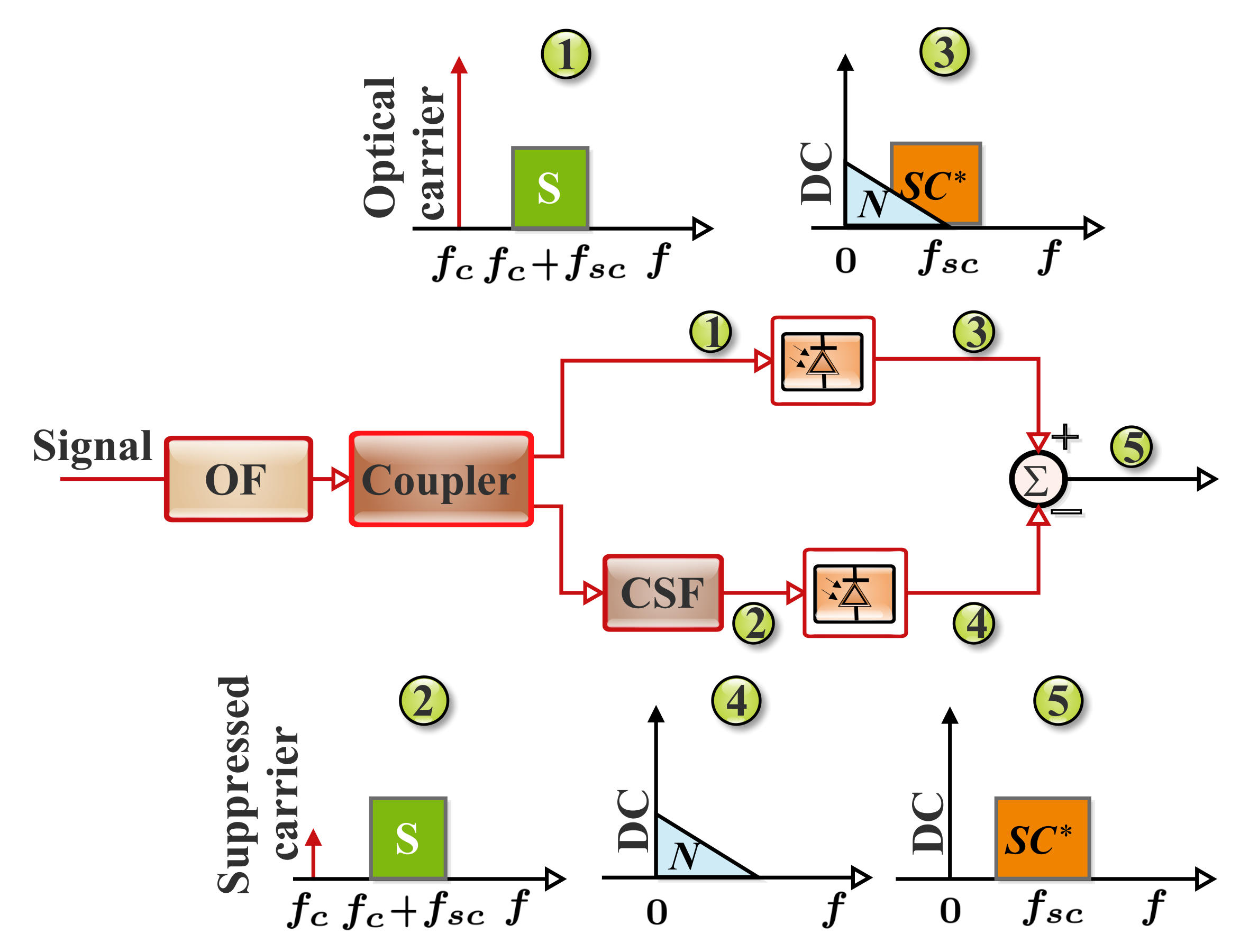
Single-Stage Linearization Filter Approach

The Rx-DSP configuration that is based on a single-stage linearization filter (SSLF) and the Rx-EDC is illustrated in Figure 7a. In the SSLF block, a digital SSB signal is acquired from the detected electrical DSB signal by means of a sideband filter (SF) [29]. Furthermore, in this scheme, the SSBN terms are treated as a perturbation to the signal [22]. Then, the SSBN terms’ waveform approximation is estimated in accordance with the SSB signal and subtracted from the SSB signal that has been filtered. This process helps the partial compensation of the SSBN [31]. Therefore, the performance difference between the Tx-EDC and Rx-EDC can be reduced with the implementation. Moreover, for both EDC schemes, the transmission performance over a range of launch powers can be enhanced. A notable benefit of this scheme is the offered DSP structure, which is very simple, resulting in a significantly low DSP complexity implementation [29]. In view of the fact that the SSBN terms’ calculation is realized right from the detected signal, as opposed to its reconstruction based on the symbol decisions, as usually done in the SSBN estimation and cancellation algorithm, it reduces the DSP complexity considerably. It averts the requirement for precise symbol decision-making in the course of the beating terms’ reconstruction [22]. Nevertheless, since the SSBN terms estimation is in line with the received distorted signal, extra beating interference is presented by the scheme. This considerably limits the compensation performance [29].

Two-Stage Linearization Filter Approach

The SSLF approach can be improved by adopting a two-stage linearization filter and the Rx-EDC in the Rx-DSP design as depicted in Figure 7b. The main limitation of the SSLF approach is the introduced beating interference, which is largely the signal-SSBN beating products. This issue can be addressed by employing another linearization stage in addition to a stage being employed in the SSLF approach. This will facilitate the elimination of the unwanted beating interference that emanates from the first linearization stage. Therefore, the second stage helps further improve the compensation gain. Furthermore, it can help the Rx-EDC to have an enhanced BER performance and transmission performance comparable to those of the Tx-EDC. The small difference that could occur between the BER Rx-EDC and Tx-EDC can be attributed to the uncompensated residual beating terms being caused by the linearization filter in the second stage [29].

Iterative Linearization Filter Approach

Another viable solution for improving the Rx-DSP performance is the iterative linearization filter and Rx-EDC implementation. The iterative linearization filter scheme can further help enhance the SSLF and two-stage linearization filter performance. In this approach, the detected signal waveform is initially stored in the memory as illustrated in Figure 7c. Subsequently, the SSBN is determined according to the sideband-filtered signal. Then, the resulting signal can be subtracted from the stored signal waveform so as to alleviate the SSBN [57,58]. The procedure will then be iterated several times with the intention of accomplishing a maximum compensation gain. Furthermore, based on the iterative linearization filter, an identical BER performance can be realized with the Rx-EDC and Tx-EDC. Although significant compensation performance improvement can be offered by the scheme, it presents additional DSP complexity compared to the single- and two-stage linearization filters methods. This can be mainly attributed to the required multiple iterations [29,118]. Besides the significant latency that can be incurred, the associated iterations can considerably increase the DSP power consumption [50]. One means of addressing this is by combining a tunable frequency gap between the data sideband and the optical carrier. This will help alleviate the estimation burden of the iterative detection and flexibly improve the system performance within reasonable iterations [118]. However, this could be at the expense of the SE.

SSBN Estimation and Cancellation Approach

The Rx-DSP that comprises the SSBN estimation and cancellation technique in addition to the Rx-EDC is depicted in Figure 7d. This technique presents compensation performance that is comparable to that of the iterative SSBN cancellation scheme. Unlike the iterative SSBN cancellation scheme, the need for multiple symbol decision-based SSBN reconstruction procedures that demand multiple IFFT/FFT pairs is prevented. Furthermore, the scheme entails having two replicas of the detected signal. A copy is stored in the memory, while the other is sent to an SSLF that offers partial elimination of the SSBN terms. Then, a noniterative SSBN estimation and cancellation is executed to construct an approximation of the SSBN. Subsequently, the resulting signal is subtracted from the signal waveform that is stored in the memory [29,59]. It is noteworthy that no additional unwanted beating product is presented by the scheme, as is usual in the case of the linearization filtering schemes. Consequently, the SSBN estimation and cancellation scheme presents an improved compensation gain in particular, at the higher OSNR values. Nonetheless, the dependency on the symbol decision accuracy is the main limitation of the scheme. This limitation results in performance degradation at lower OSNR levels [29].

Kramers–Kronig Approach

The Rx-DSP that exploits the KK algorithm and the Rx-EDC is shown in Figure 7e. Rather than considering SSBN terms as a perturbation that should be eliminated as in the case of other linearization approaches, the KK algorithm reconstructs the optical phase of the transmitted SSB signal based on its detected intensity [22]. It is noteworthy that out of all the linearization schemes being considered, the KK algorithm offers the best performance [29,50,55]. Based on this, we give further information on the KK algorithm and the means of addressing the associated challenges in Section 5.
In general, to realize an ultimate compensation gain, the amplitude scaling factor, η ( ) , used in the linearization scheme has to be optimized. In a configuration that exploits a scaling factor, it can be optimized by sweeping its value and then choosing the best value that can realize the minimum BER. Furthermore, for the scheme that has two scaling factors, the scaling factor of the primary linearization stage is firstly optimized. Therefore, based on the optimized value of the first stage, the second scaling factor can also be optimized. In addition, either the Tx-EDC or Rx-EDC can be employed in the DD scheme when an appropriate linearization technique is implemented. It is remarkable that the performance difference between both EDCs depends mainly on the adopted linearization scheme’s effectiveness. Moreover, a summary of SSBN mitigation techniques is given in Table 5. Furthermore, provided that the beating interference is effectively suppressed, both EDCs can accomplish comparable performance. With the Rx-EDC, the system operation can be considerably simplified, resulting in relatively low system complexity. This is due to the link dispersion knowledge that is not demanded at the transmitter [29].

5. Kramers–Kronig Detection Scheme

In this section, the principles of the KK algorithm regarding both the conventional and the modified KK schemes are considered. Likewise, the impact of different related factors on the KK algorithm is deliberated.

5.1. Principles of the KK Algorithm

An SCOH KK scheme is a direct detection Co-Rx in which the cost-effectiveness of the direct detection system and the high-performance benefits of COH transmission are jointly exploited. As previously mentioned, for a minimum-phase optical SSB signal, the phase information can be retrieved from its intensity by the KK relation. This offers a high potential for the direct detection optical SSB signal that is really robust to the linear transmission impairments and SSBN. Nonetheless, one of the related technical challenges of the conventional KK scheme implementation is the requirement for the DSP block to function at a sampling rate that is faster than the one stipulated by Nyquist. This challenge can be associated with certain nonlinear operations such as the exponential and logarithm functions that are required in the KK algorithm [119]. The associated nonlinear operations can considerably broaden the spectrum of the signal. Consequently, to address the induced spectral broadening, it is imperative to implement a digital upsampling prior to the DSP [18,43,44,120]. Furthermore, detailed information on why digital upsampling is essential was given in [43]. Based on this, a larger memory and faster processing speed are demanded in the KK algorithm’s DSP chip. Experimental demonstrations have also revealed that to realize an optimum receiver sensitivity, typical values of the required samples per symbol are in the range of 4–6 Sa/symbol, [29,30,45,46,61,109]. Therefore, the KK scheme’s real-time implementation may be hindered by the increase in the number of samples at DSP. Moreover, DSP can be implemented in parallel to lower the specified processing speed of the chip. However, the power consumption and complexity will be considerably increased [44,46]. Based on this, it is highly important to modify the KK DSP algorithm. In the following subsections, the conventional KK algorithm, as well as the modified alternatives are discussed.

5.1.1. Conventional KK Algorithm

A typical block diagram of the conventional KK scheme is depicted in Figure 8. Complex optical data s ( t ) exp ( j ω s t ) are superimposed on a copolarized reference optical carrier c exp ( j ω c t ) with a real-valued amplitude c at the transmitter. In this regard, an optical signal, E ( t ) , that impinges on the direct detection receiver can be defined as [21]:
E ( t ) = c + s t e j ω Z t e j ω c t ,
where ω Z = ω s ω c .
In addition, the KK concept is based on the application of the Hilbert transform to an analytic time signal with known amplitude information only. Moreover, if the spectrum of the signal, a ( t ) = s ( t ) exp ( j ω Z t ) , does not extend to negative frequencies, then it is analytic. Furthermore, in accordance with the KK concept, the carrier has to be sufficiently large to fulfill the minimum-phase condition (i.e., | s ( t ) | < c ) with a reasonably high degree of confidence. In reality, this indicates that the CSPR must be larger than the signal PAPR to ensure a perfect DSP-based phase retrieval. Furthermore, it should be noted that the optimal CSPR required for a related PAPR depends on parameters such as the OSNR, the employed modulation format, and the received signal pulse shape [21].
In addition, for a receiver with responsivity R with R = 1 , after the square law detection by a single-ended PD, a current, I ( t ) , that is proportion to the received electrical signal power can be realized as [44,45,46]:
I ( t ) = | E ( t ) | 2 = | c + s t e j ω Z t | 2
It should be noted that there are some contributions from the signal–signal beating | s ( t ) | 2 , the signal–carrier beating 2 { c s ( t ) exp ( j ω Z t ) } , as well as carrier–carrier mixing, c 2 , to the power spectrum of I ( t ) , as illustrated in Figure 8 [21]. Furthermore, an ADC is then used for sampling and quantizing the photocurrent I ( t ) . Subsequently, the function ln I ( t ) is estimated from the measured data, where ln denotes the natural logarithm operation. It is noteworthy that an unlimited number of higher harmonics will be generated due to the associated nonlinearities of the operation. Therefore, before executing the nonlinear operations, the output data of the ADC has to be sufficiently upsampled to inhibit aliasing errors [21,44,45,46,119].
The conventional KK algorithm retrieves the phase information, φ ( t ) , from the intensity information via the Hilbert transform as:
φ ( t ) = H [ ln I ( t ) ] .
Consequently, the electrical field, E ( t ) , of the downconverted optical signal, can be recovered as:
E ( t ) = I ( t ) exp [ j φ ( t ) ] = c + s ( t ) exp ( j ω Z t ) .
The next process is the removal of the reference carrier. Furthermore, the subsequent signal can then be shifted from the intermediate frequency, ω Z , to the baseband. Thus, the obtained complex data signal s ( t ) can be defined as [21]:
s ( t ) = i ( t ) exp [ j φ ( t ) ] c e j ω Z t .
Moreover, digital downsampling can also be implemented and further DSP such as electrical equalization, carrier recovery, and demodulation can then follow [21,44,45,46]. In the following subsection, we discuss a number of modifications to the conventional KK algorithm.

5.1.2. Modified KK Algorithms

As stated earlier, some technical challenges require significant attention for the effective implementation of the KK algorithm. Table 6 presents some modification efforts to address the issues. They are grouped by the matter that they tried to address. For instance, some schemes tried to address the required upsampling, while some focused on the demanded high CSPR. However, it has been observed that for perfect reconstruction, most of the efforts usually achieve their aims at the expense of additional penalties that are related to factors such as CSPR, complexity, latency, bandwidth, and cost.
As previously mentioned, the spectral broadening is a result of nonlinear operations, and a viable solution has to find a way of getting around their execution. This can be achieved by exploiting a DSP algorithm that isdigital upsampling-free [18]. For instance, suitable mathematical approximations can be employed to get around the associated nonlinear operations of the conventional KK algorithm. In this context, the square root of I ( t ) can be approximated to a second-order binomial expansion. Furthermore, by exploiting the minimum-phase condition, the phase of the signal can also be approximated. The function, ln I ( t ) , can also be approximated based on the second-order Taylor expansion [45,46]. Unlike the conventional KK algorithm that operates at 6 Sa/symbol, the algorithm that is based on mathematical approximations can operate at 2 Sa/symbol [46]. Moreover, the implementation is capable of exhibiting similar performance to that of the conventional KK scheme [46]. Besides the logarithm function that can be approximated, the exponential function can also be eliminated through the Cartesian-form representation of the complex signal [44].
It is noteworthy that some approaches may still comprise some nonlinear operations such as square and square root functions in the modification process. Nevertheless, a comparative study has established that the associated nonlinear operations of the upsampling-free KK algorithm present a negligible contribution to the spectral broadening. However, the upsampling-free algorithm limitation is that the performance difference between its implementation and the conventional KK algorithm can be significant when the required SNR is absolutely high [44]. Owing to the related multiple iterations of some approaches, considerable complexity and latency can be incurred by their application [18].
Additionally, to satisfy the minimum-phase condition, the conventional KK system demands a strong CW tone whose amplitude is comparatively greater than that of the information-bearing signal. When the minimum-phase condition is met, the field reconstruction can be accurately achieved through the KK relation at the expense of a high CSPR [48,49]. However, the requirement for a strong carrier imposes a significant limitation on the transmitter and can also increase the nonlinear fiber propagation effects in the direct detection systems [49]. Consequently, the concern about the high CSPR is the additional sensitivity penalty being presented [48]. As a result, it is highly imperative to ease the CSPR constraint without making any significant sacrifice of the system performance [51]. In this regard, there have been concerted efforts on the means of lowering the required CSPR in the conventional KK system. For instance, an enhanced KK algorithm that is capable of accomplishing the conventional KK scheme’s performance but with a ∼3 dB lower CSPR can be employed [49]. The scheme integrates a flexible adaptive dispersion compensation into its algorithm, and it is based on an independent, but direct intensity measurement of the received signal replicas. In this, two replicas are measured, and one of the replicas is to some extent dispersed compared with the other. However, the scheme presents additional hardware (i.e., a dispersive element, an optical splitter, and an optical demultiplexer) cost due to the requirements of two independent direct detection paths [49] and high iterative DSP [50]. It should be noted that the related cost can be insignificant in shared WDM channels [49].
The required high CSPR for the KK subsystem can also be relaxed by exploiting an enhanced SSBN mitigation algorithm that is based on the KK relation. The scheme can offer a reduction in the optimal CSPRs, and the OSNR can be improved as well. For instance, a 2–3 dB reduction in the CSPRs can be realized [51]. A modified KK algorithm that functions in comparatively low CSPR conditions has been demonstrated [52]. Unlike the conventional scheme where a strong CW is just appended to the complex SSB signal to fulfill the minimum-phase condition, in the presented reconstruction scheme, an exponential operation is applied to the complex SSB signal. Therefore, the required condition is inherently satisfied, and the original signal can be accurately reconstructed even at a low CSPR value. Nevertheless, the scheme just retrieves the information-bearing signal rather than the optical field. The scheme can also be modified to reconstruct the optical signal field by means of the KK relation. However, this is at the expense of the spectral broadening caused by the exponential operation. This results in the need for a greater system bandwidth compared with the conventional KK scheme [48].
In addition, it has been observed that most of the KK algorithm modification efforts to either prevent the use of digital upsampling or implement limited upsampling have deviated from the fundamental algorithm by employing a number of linear approximations for the nonlinear operations of the KK algorithm. Based on this, most of the modified algorithms achieve their objectives at the expense of a measurable power regarding the required CSPR for perfect reconstruction. In this context, an alternative approach to the approximation-based algorithm modification with minimal modification can be employed. Furthermore, the approach can offer suitable performance at a relatively lesser CSPR penalty [43].
Furthermore, the requirement for extensive DSP can also be addressed. This can be achieved by exploiting the scheme that is based on a SiP hardware SSBN cancellation [50]. The scheme is based on the concept that the SSBN can be removed through either software- or hardware-based approaches. The software-based SSBN cancellation approach prevents additional hardware complexity. However, they usually require an iterative process to effectively alleviate the effect of inessential elements that can hinder the desired signal [18]. On the other hand, the minimum-phase condition is not required in the hardware-based SSBN cancellation. This results in a lower achievable CSPR compared with the software-based cancellation. Besides the SSBN cancellation, a relatively lower cost and a smaller footprint can be achieved with the implementation. Compared with the enhanced KK scheme, the required CSPR can be lowered by 3 dB without any complexity increase [50]. Likewise, there are experimental efforts on the means of optimizing the performance of the KK scheme through the simultaneous consideration of the related CSPR value and digital upsampling. For instance, in [30,61], the joint optimization of the CSPR at the transmitter and DSP resampling rate in the KK scheme within the receiver was considered through sweeping, to identify the optimum values.

5.2. Related Impact on the KK Scheme

In this subsection, the associated impacts of different factors such as chromatic dispersion, the optoelectronic frontend, and I Q imbalance on the KK subsystem are presented. Considerable attention is given to the laser-related impact on the KK system’s performance.

5.2.1. Opto-Electronic Frontend

The KK receivers have demonstrated high potential for full-optical field reconstruction in one polarization by employing a single PD such as the heterodyne detection. However, unlike heterodyne detection, the required CSPR is much more relaxed. Furthermore, signal distortions (i.e., chromatic dispersion) that might have occurred prior to the square law detection can be compensated after optical field reconstruction [121]. Nonetheless, the KK reconstruction algorithm is susceptible to the signal distortion that occurs between square law detection and KK processing [19]. Therefore, for an effective optical field reconstruction, the squared magnitude of the optical field has to be fed into the KK algorithm without further distortions that might emanate from the digitization processing and optical-to- electrical (O/E) conversion. In a practical receiver, this is not usually the case, and distortion is normally induced by the O/E conversion frontend transfer function. In general, the receiver has bandwidth limitations and the residual phase and magnitude responses of its associated components such as transimpedance amplifier, PD, and ADC. It should be noted that if the electrical distortion is not compensated, it can bring about residual SSBN and can equally affect the optical field reconstruction [19,121].
Moreover, the impact of receiver bandwidth limitations on the KK algorithm has been studied, and it has been numerically demonstrated that even with moderate receiver bandwidth limitations, a significant OSNR penalty can be induced. Similarly, it has been experimentally demonstrated that adaptive equalizer employment prior to the KK processing can alleviate the O/E frontend bandwidth limitation impact on the KK field reconstruction and subsequently enhance the system performance [19,121]. Furthermore, the impact of the magnitude and phase distortions has been considered, and it has been revealed that the magnitude response presents a much more stringent impact compared with the phase response. However, in the course of KK detection, a slight phase response can induce an ∼0.5 dB penalty [19]. An abrupt change in the amplitude or phase can also result in a more severe penalty. In general, for an effective optical field reconstruction, the phase and magnitude distortions that might have occurred within the signal bandwidth have to be compensated prior to the KK algorithm’s application [19].

5.2.2. Laser-Related Effects

Additionally, it has been demonstrated that the KK implementation is sensitive to laser detuning from the center of the channel [122]. Moreover, it has been demonstrated experimentally that in spite of the SCOH direct detection nature, laser phase noise has a severe impact on the KK transmission performance, owing to its interactions with both fiber chromatic dispersion and a strong optical carrier. In that work, the system performance with distributed feedback and fiber lasers was compared at 11 dB CSPR. The presented results demonstrated a considerable performance gain for fiber laser employment. The gain was due to the low linewidth and frequency stability of the fiber laser. This resulted in a lower performance penalty by the interaction of dispersion and phase noise during propagation [123]. This implies that the employment of a low-quality laser with a high linewidth can bring about substantial degradation in the transmission performance. In [124], by considering the equalization-enhanced phase noise (EEPN) and phase-to-amplitude noise conversion, the impact of laser phase noise on direct detection transmission with the KK scheme was analyzed.

5.2.3. Fiber Dispersion

The KK algorithm can effectively mitigate SSBN, and it can digitally compensate the chromatic dispersion. In [125], the impacts of the chromatic dispersion on both KK and SSBN iterative cancellation receivers were investigated. Both receivers can effectively accomplish field recovery and with a comparable SE. However, the KK algorithm depends on the minimum-phase condition to reconstruct the optical field. Based on this, it demands a suitably high CSPR [125].
In addition, it has been demonstrated that the optimal CSPR value for the KK scheme increases with an increase in the transmission distance. This is owed to an increase in the chromatic dispersion-induced PAPR that violates the minimum-phase condition [51]. As a result of this, the field cannot be accurately recovered, resulting in transmission performance degradation. Therefore, the OSNR sensitivity of the KK algorithm depends on the chromatic dispersion. On the other hand, the IC receiver has no limitation on the minimum-phase condition. Consequently, it demonstrates high robustness against chromatic dispersion irrespective of the CSPRs. Therefore, the IC receiver is insensitive to chromatic dispersion, while the KK subsystem is sensitive to it. To be robust against chromatic dispersion, a relatively high CSPR is required by the KK scheme, resulting in an increment in the optimal CSPR [125]. Although the KK algorithm is sensitive to chromatic dispersion, for short-reach applications, polarization mode dispersion is not a main limiting factor [126].

5.2.4. IQ Imbalance

The effective implementation of the KK algorithm depends mainly on the SSB-modulated signal. A usual method of generating an optical SSB signal is by the I Q M , as discussed in SubSection 4.1. In an I Q M , for the perfect generation of an SSB signal, the I port and Q port are driven via the DSB upconverted signal and its related Hilbert transform, respectively. In this regard, an SSB signal will be generated through the seamless cancellation of one sideband by the combination of the Hilbert transform pairs. Furthermore, to fulfill the minimum-phase condition, it is imperative to add a strong CW optical carrier to the signal [127].
It is noteworthy that the I Q M is most efficient when biased at null. This means better electrical spectrum efficiency as it generates two sidebands. This implies an improved power efficiency. Therefore, any configuration that deviates from this will suffer either electrical spectrum efficiency or power efficiency degradation. Furthermore, the practical challenges of the I Q M implementation to generate the optical SSB signal are timing misalignment, amplitude imbalance, and I Q phase mismatch between the I and the Q components of the signal. Likewise, these factors will significantly affect the suppression ratio of the optical sideband. Consequently, the resulting I Q imbalance of the modulator causes the minimum-phase condition violation and generates interfering DSB distortion components in the optical spectrum. These result in the performance degradation of the KK system. Moreover, the subsequent limitation of the I Q imbalance on the back-to-back performance is owed to the minimum-phase condition, while its associated degradation in the transmission performance is due to dispersion-induced RF power fading [127].

6. Transceiver Architectures’ Classification and Basic Concepts

This subsection focuses on the transceiver architectures and their related features such as the achievable optical spectrum efficiency (OSE), support for the digital compensation of chromatic dispersion at the receiver, and the minimum required electrical bandwidth of the receiver [14]. The transceiver architecture can be broadly classified based on the offered DoF or the number of dimensions, as illustrated in Figure 9.

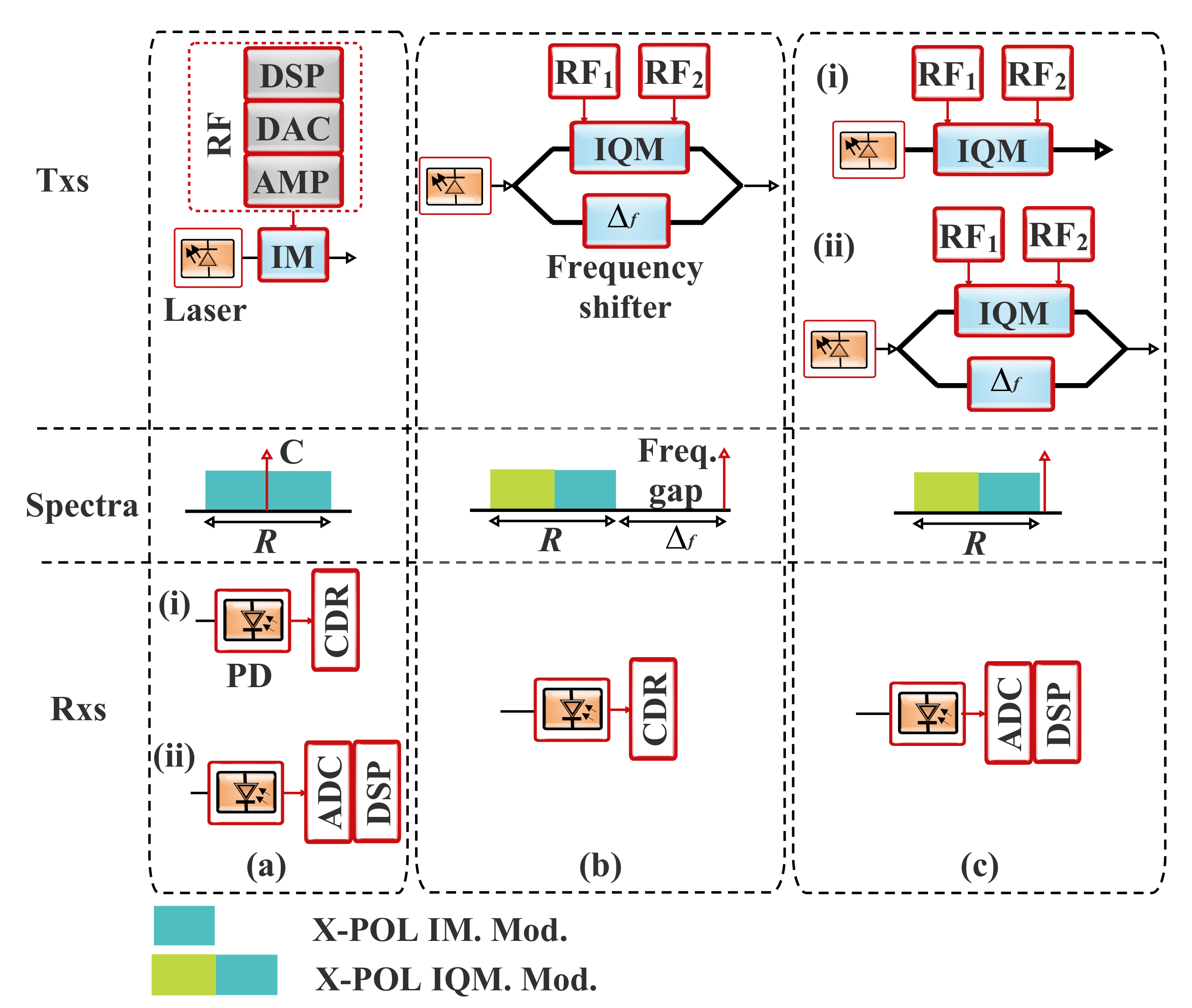
6.1. 1D-Based Architectures

The 1D-based architectures exploit just one DoF and are presented as follows:

IM-DD

The IM-DD is a 1D scheme that offers the simplest configuration. Its transmitter is based on the IM, and the receiver is based on direct detection, as depicted in Figure 10a. The radio frequency (RF) signal modulates the light wave intensity from the CW laser at the transmitter. In regard to the CW laser frequency, the obtained optical spectrum after modulation is a double-sideband (DSB) signal in which a strong CW tone is located precisely in the middle, as well as locked “in-phase” with the information-bearing signal [17]. At the receiver, the intensity of the received optical signal is detected by a photodiode (PD). Therefore, the transmitter and receiver arrangement is usually referred to as the IM-DD scheme. Furthermore, depending on the adopted technique, a 1D IM-DD scheme can be realized without or with a digital-to-analog converter (DAC) or analog-to-digital converter (ADC) and DSP at the receiver, as depicted in Figure 10a(i) and Figure 10a(ii), respectively [10,14].
Moreover, regarding the achievable optical spectrum efficiency, the IM-DD scheme can realize 25% optical spectrum efficiency with reference to a DP-COH system. Digital chromatic dispersion compensation is not supported due to the undetected phase information of the received field. Furthermore, the optical spectrum of an IM-DD signal is conjugate symmetric around the optical carrier. This is in view of the fact that the baseband RF signal is real. Similarly, for effective detection of an IM signal with an optical bandwidth, R, the minimum required electrical bandwidth of the receiver is R / 2 [14].

IG + Offset C/DD

The I Q + shifted (offset) C scheme is a variety of the SCOH systems that frequency multiplexes a frequency shifted copy of the transmitter laser with the modulated signal. The scheme is depicted in Figure 10b. At its transmitter, a shifted copy of the CW laser is inserted into the complex modulated signal, while a frequency gap that is equal to R is maintained between the signal and tone. At the receiver, owing to the adequate frequency gap, a single PD with electrical bandwidth 2 R offers the bandpass carrier–signal beating where the unwanted SSBN can be removed by means of filtering in DSP. Therefore, the DSP stack of the I Q + C SCOH scheme demands the SSBN cancellation stage. Likewise, the reconstructed field can be chromatic dispersion compensated after SSBN cancellation [14].

IQ + C/DD-KK or DD-IC

The I Q + C scheme is illustrated in Figure 10c. It is similar to the I Q + offset C system, but it doubles the SE. Because the related frequency gap between the carrier and the signal in the I Q + offset C system is eliminated in the I Q + C scheme, the CW tone is transmitted in proximity to the spectrum edge. Furthermore, the tone can be appended at the transmitter either electrically (Figure 10c(i)) or optically (Figure 10c(ii)). In the former approach, suitable sinusoids can be added to the modulating RF signals from the DACs that drive the I Q modulator ( I Q M ). However, some RF swing is sacrificed in this approach for tone generation. In the latter scheme, a power split portion of the transmit laser is frequency shifted for the tone generation. Nevertheless, this approach demands a second modulator that can be used for frequency shifting. At the receiver, to recover the field information of the carrier–signal beating, the SSBN can be removed through DSP using either interference cancellation (IC) or any SSBN mitigation scheme, as discussed in Section 4.2. Furthermore, the minimum electrical bandwidth of the receiver is R. Digital chromatic dispersion compensation is supported at the receiver [14,18,29,119].

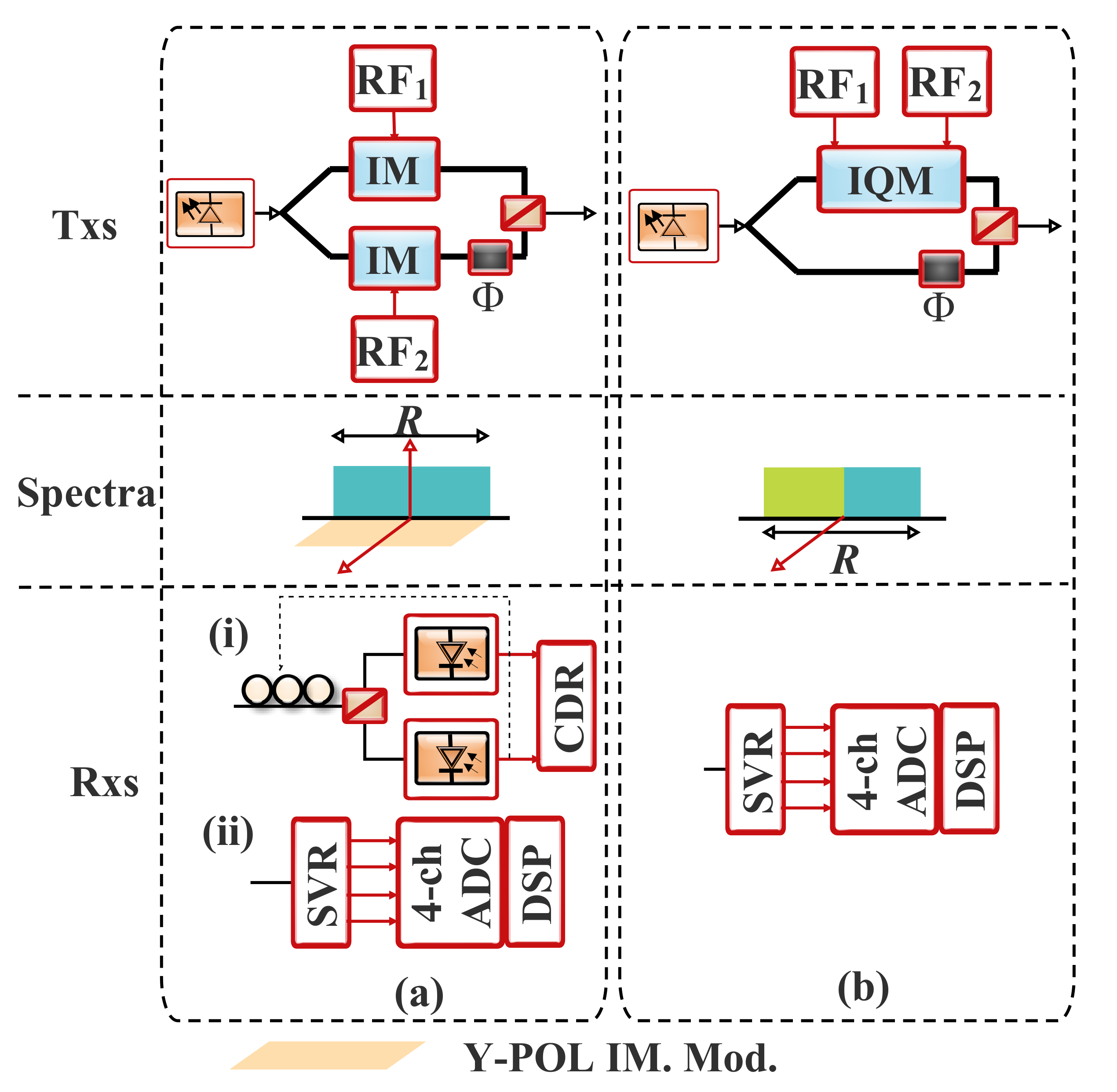
6.2. 2D-Based Architectures

There are enormous opportunities when the exploited DoFs are two rather than one. Based on this, there is a unique window of opportunity to seize the offered advantages while a self-beating direct detection scheme is still maintained. There are a number of 2D-based architectures, and some of the potential ones are presented.

6.2.1. DP-IM/DD DP-IM or the Stokes Vector Receiver

The DP-IM/DD DP-IM or Stokes vector receiver exploits two DoFs to enhance the system performance, as shown in Figure 11a. Furthermore, with the DP-IM scheme, two RF signals can be encoded on the intensities of orthogonal polarizations of a single laser at the transmitter [14,33,34]. Furthermore, two potential receiver structures for the DP-IM based transmitter are the direct detection receiver (Figure 11a(i)) and Stokes vector receiver (Figure 11a(ii)). Based on the former implementation, a DSP-free receiver that employs a polarization beam splitter (PBS) and two PDs can be employed to detect the DP-IM signal. However, the implementation demands optical polarization tracking to avoid polarization wandering. On the other hand, as expatiated in Section 8, based on the latter structure, polarization demultiplexing can be achieved with the aid of a Stokes vector receiver with the outputs feeding four ADCs that are followed by a MIMO DSP unit. The employed MIMO filter bank in the Stokes vector receiver accomplishes Stokes space-based polarization derotation. It also facilitates residual ISI mitigation [14,23,34].

6.2.2. PolMux I Q + Carrier (C)/Stokes Vector Receiver

As the DP-IM/DD DP-IM/Stokes vector receiver, the PolMux I Q + C /Stokes vector receiver scheme exploits two DoFs to enhance the system performance, as illustrated in Figure 11b. For instance, it employs the signal I and Q parts along with the CW carrier (C) at the transmitter. Therefore, in the PolMux- I Q + C scheme, at the transmitter, two RF signals are encoded on two orthogonal phase quadratures (I and Q). Furthermore, a copy of the carrier is multiplexed with the I Q signal on the orthogonal polarization [23]. The polarization derotation can be realized at the receiver using a Stokes vector receiver and the associated MIMO DSP. Subsequently, the full-complex field information can be provided on the X polarization. Therefore, with this configuration, chromatic dispersion compensation at the Rx-DSP is possible after MIMO polarization derotation [14].

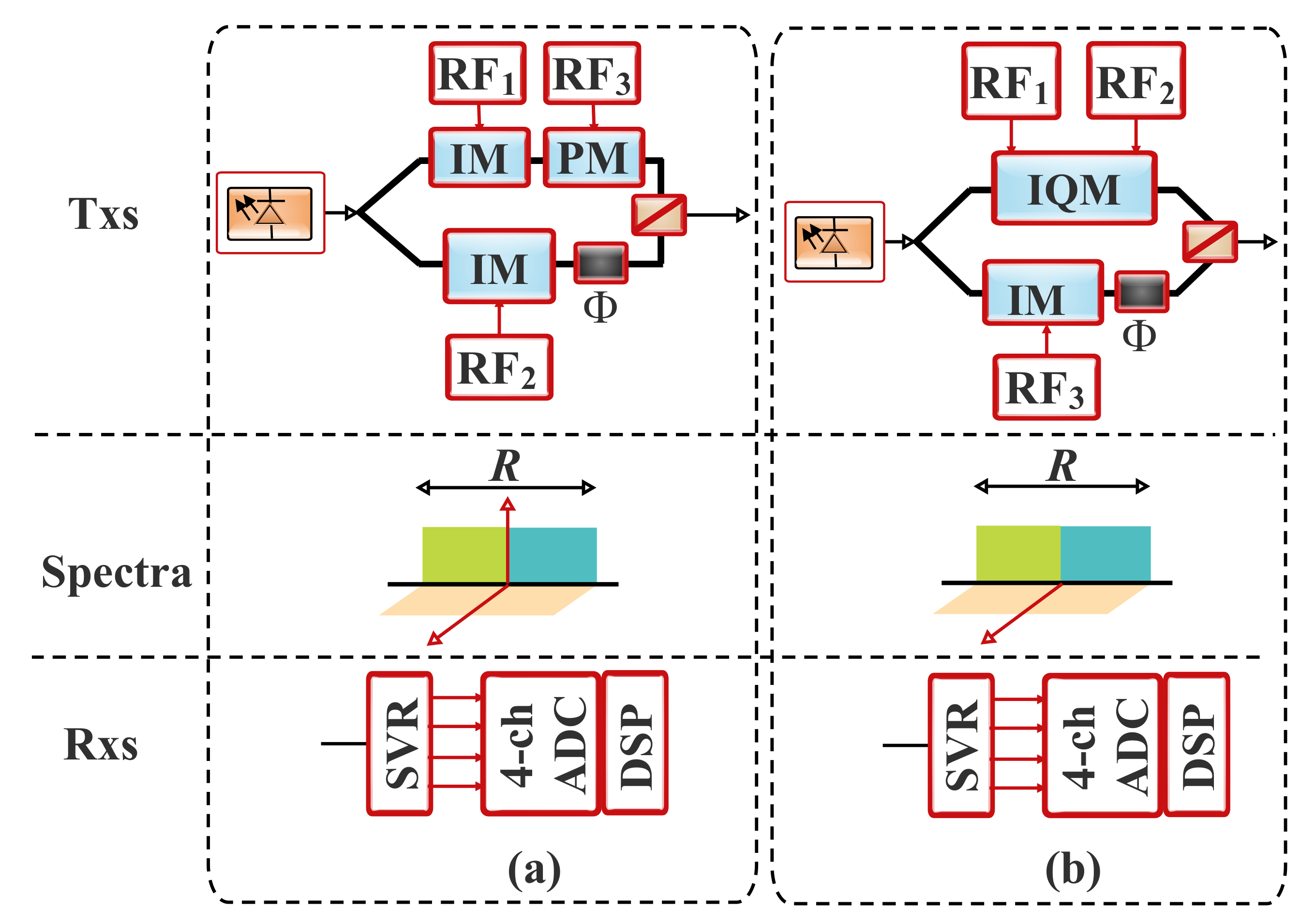
6.3. 3D-Based Architectures

The bit rate and the SE of self-beating direct detection schemes can be further increased by modulating and recovering a third DoF. To realize this, there are a number of transceiver architectures (as depicted in Figure 12a,b) and modulation formats that can be employed [14]. The signal recovery can then be achieved by means of a Stokes vector receiver [17]. The DP-IM-intensity-and-phase modulation (IPM) (Figure 12a) and PolMux- I Q -IM (Figure 12b) are instances of the 3D-based architectures. In the schemes, a third RF signal is encoded by employing complex modulation on one polarization component [14], while a real-valued IM is adopted on the other [37,128]. Therefore, in these schemes, the optical spectrum is conjugate symmetric on one polarization, while it is asymmetric on the other [14]. As the PolMux I Q + C /Stokes vector receiver scheme, polarization derotation can be realized at the receiver by employing a Stokes vector receiver and the associated MIMO DSP algorithms.

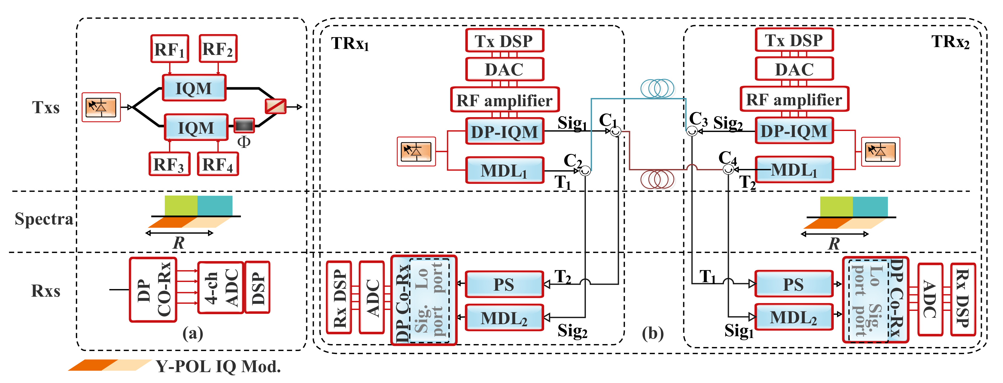
6.4. 4D-Based Architectures

The DP-COH schemes are illustrated in Figure 13. In the DP-COH scheme in Figure 13a, the receiver configuration that leverages an LO to extract the phase information of the interfered signal is the Co-Rx. Instances of this configuration are homodyne and heterodyne receivers [10]. The DP-COH configuration serves as a benchmark for comparing other configurations. Furthermore, as discussed in Section 7.1, through the complex modulation of the two polarizations, the available four DoFs are exploited by the DP-COH systems. Consequently, with the aid of either one (2 × 8) or two (2 × 4) 90 hybrid and an LO laser, the DP-COH can realize both polarization and phase diversity. Furthermore, in the process, the unwanted signal–signal beating is eliminated by the balanced detection. It should be noted that the carrier recovery stage is essential in the Rx-DSP stack of the DP-COH system [14].
Furthermore, another promising architecture is the remote LO delivery (RLOD) system. The RLOD is a self-homodyne COH detection scheme with a bidirectional transmission. As the conventional COH system, it supports full utilization of the four available DoFs for modulation in optical transmission. As illustrated in Figure 13b, the schematic of the RLOD comprises two transceivers. Furthermore, each transmitter contains a transmitter DSP (Tx-DSP) that leverages the employed DAC, the output signal of which is amplified to drive the DP-IQM. Likewise, the transmitter has a laser, the output of which is split into two branches. One of the branches is employed to feed the DP-IQM for modulation, while the other one is for delivering the reference tone. Furthermore, two circulators can be employed at each transceiver side to ensure that the two lanes of the full-duplex fiber are used as bidirectional fibers rather than the usual unidirectional implementation in the conventional IM-DD systems. The modulated signal from Transceiver 1 and the tone from Transceiver 2 are coupled by the circulators C 1 and C 4 to one lane, while the modulated signal from Transceiver 2 and the tone from Transceiver 1 are coupled by the circulators C 3 and C 2 , respectively, to the other lane of the full-duplex fiber. It is noteworthy that the modulated signal and tone propagation are in opposite directions [130].
At the receiver, for coherent reception, the associated tone and the modulated signal from Transceiver 2 are extracted by the circulators C 1 and C 2 , respectively, while the transmitted tone and the modulated signal from Transceiver 1 are extracted by the circulators C 3 and C 4 for the onward distribution to the DP-Co-Rx at Transceiver 2. It should be noted that there is a polarization stabilizer (PS) in the tone path. The PS helps ensure tone–signal beating on both states of polarization. Furthermore, the time delay between the signal and tone can be synchronized with the aid of a matched delay line (MDL), which is based on matched fibers. This can aid in ensuring the same laser phase noise cancellation at Co-Rx during the tone–signal beating. Matching the signal and tone paths helps enable uncooled laser implementation. Furthermore, to facilitate the Rx-DSP, the analog output signals from the DP-Co-Rx are converted to a digital output by the ADC after COH reception [130]. In addition, different transceiver architectures are summarized in Table 7. Furthermore, efforts towards simplified architectures in which the cost-effective benefit of the 1D-based IM-DD and the enhanced AIR of the 4D-based COH systems are exploited, as well as the associated tradeoffs are discussed in Section 7.

7. Towards a Simplified Optical Transceiver

The concepts and need for an SCOH system for short- and medium-reach applications such as DCNs are comprehensively discussed in this section. Moreover, with reference to the COH detection and the IM-DD, the relative benefits and classifications of the SCOH schemes are presented.

7.1. Full Coherent Optical System

Before discussing the SCOH, we focus on the fundamental principle of COH optical systems. In this context, various detection schemes such as homodyne, heterodyne, and phase-diversity homodyne are considered in conjunction with different means by which they measure the complex amplitude of an optical signal.

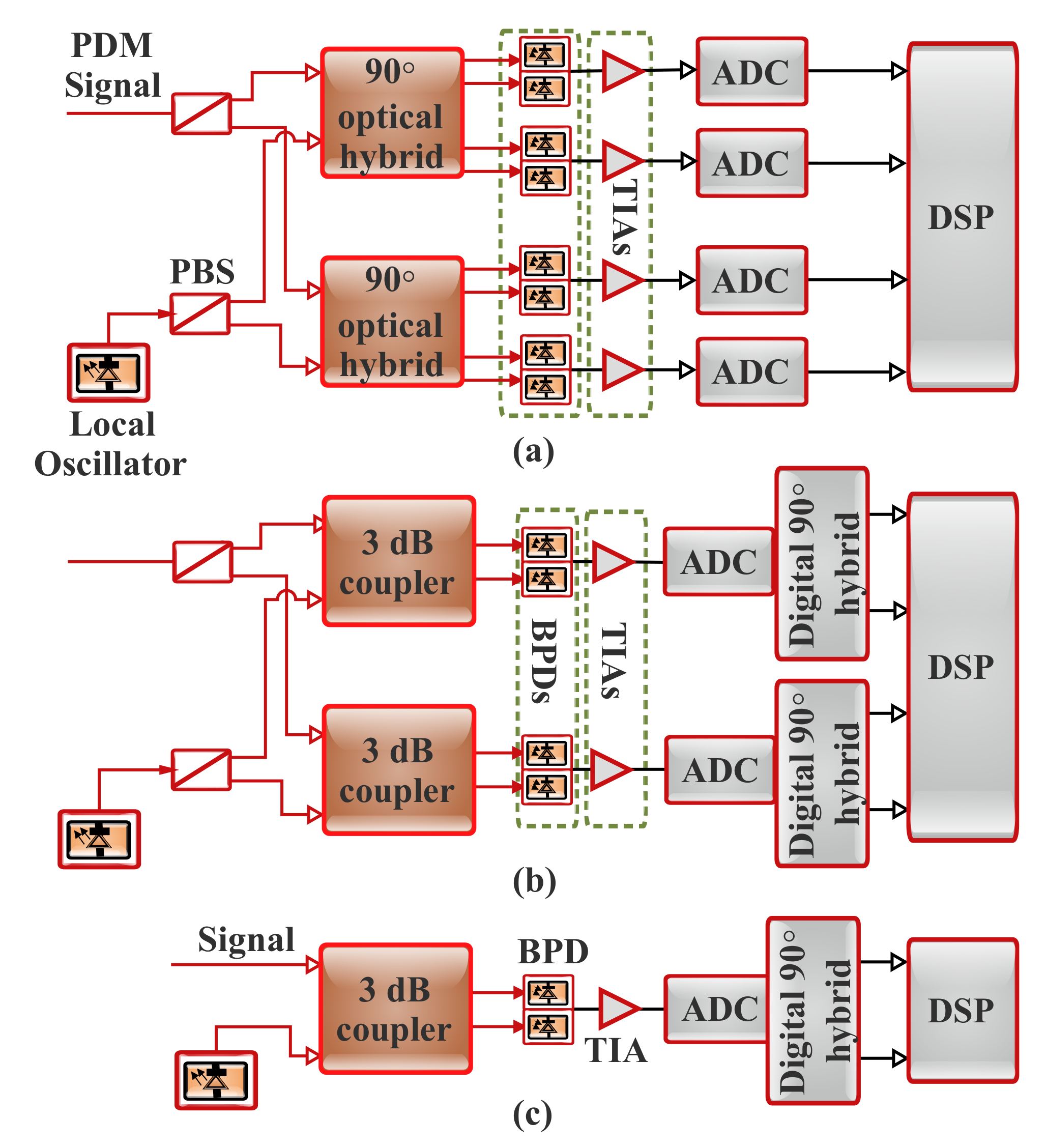
7.1.1. Optical Coherent Receiver Configurations

The COH system can effectively detect the full optical field [2,18,19]. Furthermore, Co-Rxs can be broadly based on two configurations, which are intradyne/homodyne and heterodyne systems. As illustrated in Figure 14, in the former (i.e., Figure 14a), a pair of balanced detectors is required per polarization, while for the latter (i.e., Figure 14b,c), a detector whose bandwidth is twice that of the former, per polarization, is usually employed [19,21]. It is noteworthy that the polarization-diverse intradyne scheme is mainly adopted in the existing Co-Rxs [18,21]. In general, a full Co-Rx implementation (i.e., Figure 14a) is usually based on components such as an LO laser, optical hybrids, either a polarization diversity system or an optical polarization tracking setup, and balanced PDs (BPDs) (i.e., four pairs) in order to suppress the SSBN at relatively lower LO powers. In Section 7.1.2, we expatiate on the fundamentals of optical coherent detection for different configurations. Furthermore, detailed information on the DSP for long-haul COH systems is available in [10,132,133]. In spite of the fact that a full Co-Rx might be an effective long-term scheme, currently, it is not a cost-efficient solution for cost-sensitive and short-reach link applications such as DCNs [18,19]. Simplified COH optical schemes have been presented to address the associated challenges of the full COH system implementation.

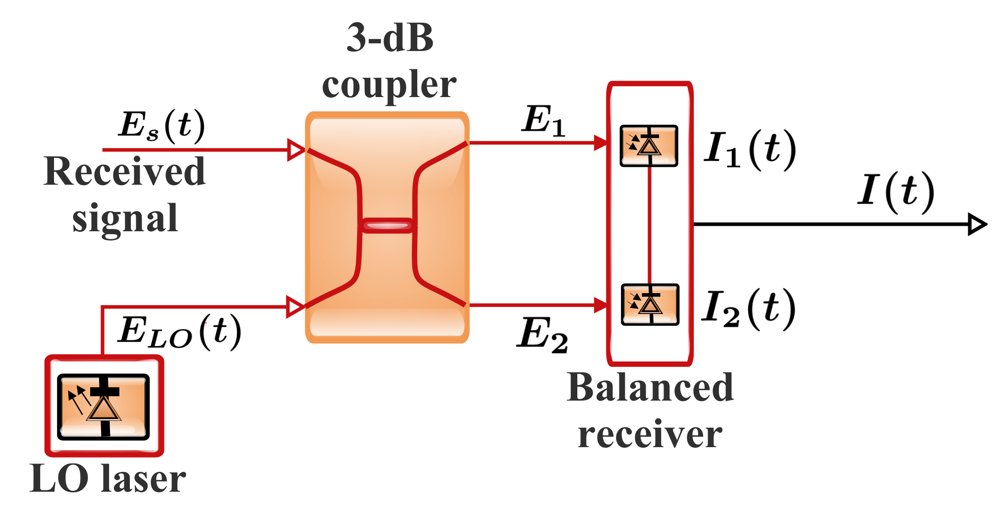
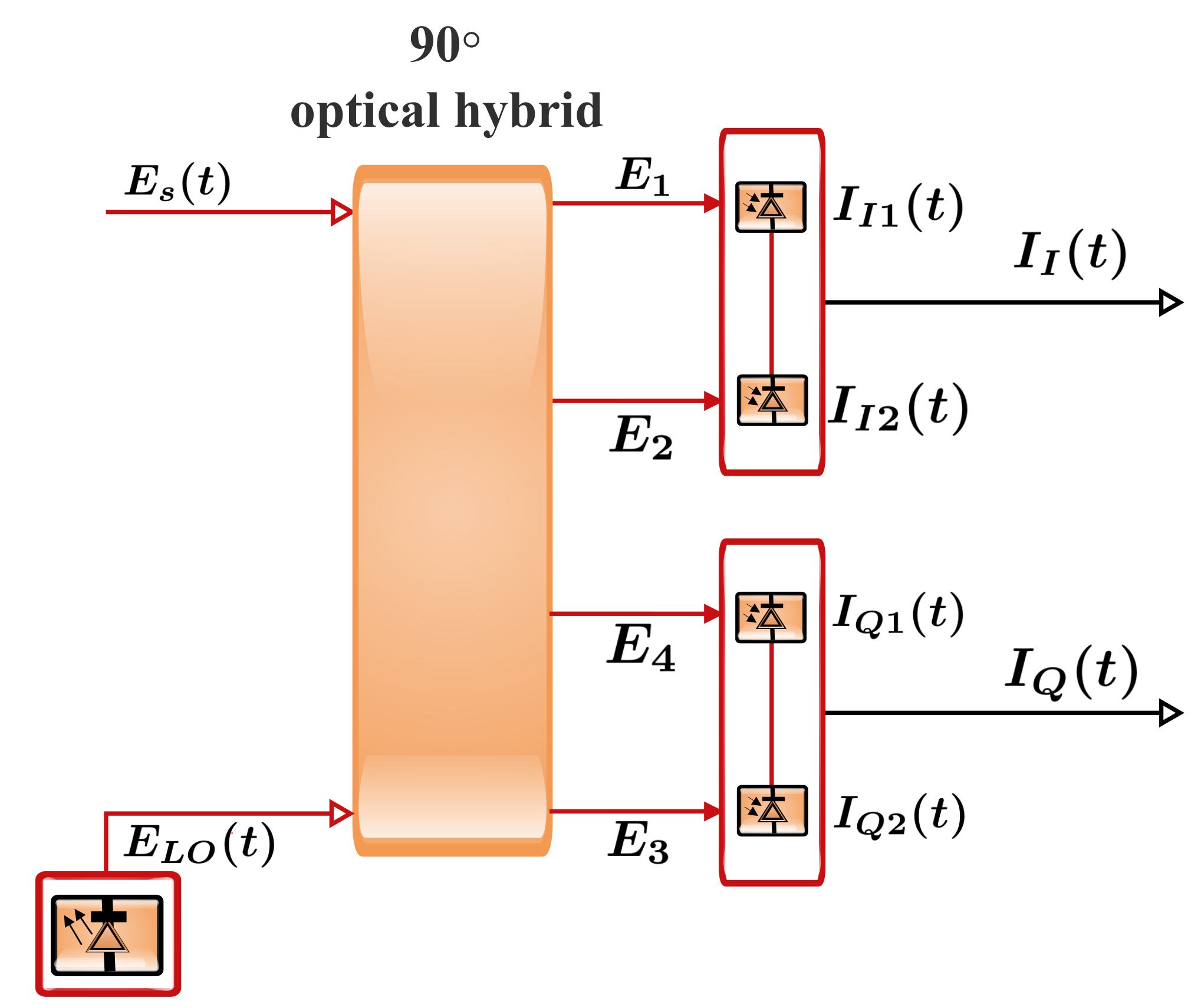
7.1.2. Optical Coherent Detection Principles

The principle of optical signal detection in the COH system can be explained by considering the configuration shown in Figure 15. The receiver measures the beat between the LO and signal. In general, when the product of the electric fields of the CW LO and modulated signal is estimated, the complex electric fields of the transmitted optical signal, E s ( t ) , and that of the LO, E LO , can be defined respectively as [10]:
E s ( t ) = A s ( t ) exp ( j ω s t ) ,
E LO ( t ) = A LO exp ( j ω LO t ) ,
where A s ( t ) denotes the complex amplitude of the optical signal, A LO ( t ) represents the constant complex amplitude of the LO, and ω s and ω LO are the angular frequency of the optical signal and LO, respectively.
In addition, apart from its ability to suppress the DC component, balanced detection also helps maximize the beat. The beating can be accomplished by a 3 dB optical coupler. The coupler ensures a 180 phase shift between the two output ports. Hence, the co-polarized signal and LO, the incident electric fields on the upper and lower photodiodes, can be expressed respectively as [134]:
E 1 =   1 2 ( E s + E LO ) ,
E 2 =   1 2 ( E s E LO ) ,
It is noteworthy that the photodiode is usually modeled as a square law detector. Its responds to the square of the electric field as:
i ( t ) = R E s ( t ) 2
Furthermore, using Equations (25a), (26a), and (27), as well as (25b), (26b), and (27), the output photocurrents produced by a pair of photodiode when illuminated by the fields E 1 and E 2 can be expressed as [10,135]:
I 1 ( t ) =   R 2 P s ( t ) + P LO + 2 P s ( t ) P LO cos ω I F t + θ I F ( t ) ,
I 2 ( t ) =   R 2 P s ( t ) + P LO DD term 2 P s ( t ) P LO cos ω I F t + θ I F ( t ) Coherent detection term ,
where ω I F denotes the intermediate angular frequency (IF) and θ I F ( t ) represents the phase information and given respectively as [135]:
ω I F = | ω s ω LO | ,
θ I F ( t ) = θ s i g ( t ) θ LO ( t ) ,
where θ s i g ( t ) denotes the phase of the transmitted signal and θ LO is the phase of the LO.
Furthermore, to obtain the aggregate photocurrent, the output photocurrents of the photodiode pair are subtracted. Hence, using Equation (28), the output of the balanced detector can be expressed as:
I ( t ) =   I 1 ( t ) I 2 ( t ) =   2 R P s ( t ) P LO × cos ω I F t + θ I F ( t ) .
It can be deduced from Equation (30) that balanced detection measures just the carrier–signal beating, while direct detection terms and excess intensity noise produced by the LO are eliminated. It is noteworthy that the photocurrent is proportional to P LO . Consequently, an increase in the LO power results in a relative gain in the photocurrent. Based on this, the receiver’s thermal noise becomes negligible [10,135].

Heterodyne Detection

Heterodyne detection can be considered as a scenario in which ω I F 2 π / T , where 1 / T represents the symbol rate that determines the optical carrier modulation bandwidth. Based on this, it can be inferred from Equation (30) that the signal’s electric field is downconverted to an IF signal.
Moreover, in this scenario, the signal phase can be expressed as:
θ s i g ( t ) = θ s ( t ) + θ s n ( t )
where θ s ( t ) represents the phase modulation and θ s n ( t ) denotes the phase noise. As a result, the output of the receiver can be defined as [10,134,135]:
I ( t ) = 2 R P s t P LO cos ω I F t + θ s ( t ) + θ n ( t ) ,
where θ n ( t ) represents the total phase noise, which can be expressed as:
θ n ( t ) = θ s n ( t ) θ LO ( t ) .
From Equation (32), note that the complex amplitude of the current can be defined as [10]:
I c ( t ) = 2 R P s t P LO exp j θ s ( t ) + θ n ( t ) .
In addition, for the synchronous demodulation of the IF signal in Equation (32) that is obtained through heterodyne detection, a phase-locked loop circuit is required at the IF stage. The employment of the electrical phase-locked loop helps the estimation of the phase noise and decoding of the symbol on the phasor expressed by Equation (34).

Homodyne Detection

This detection scheme applies in a scenario where ω I F = 0 . The photodiode current for this detection scheme can be expressed as:
I ( t ) = 2 R P s t P LO cos θ s i g ( t ) θ LO ( t ) .
With reference to Equation (35), the homodyne receiver determines the inner product between the signal and the LO phasors. Furthermore, for effective symbol decoding, the LO phase, θ LO ( t ) , has to track θ s n ( t ) to ensure the condition θ n ( t ) = 0 . This can be satisfied with the optical phase-locked loop implementation in the conventional coherent receiver. On the other hand, in the digital counterpart, it can be fulfilled with the aid of DSP. Nevertheless, this brings about an increase in the system complexity in practice. Based on Equation (35), one the in-phase (cosine) component can be detected, while the quadrature component (sine) is not considered. Consequently, full information on the complex amplitude of the signal cannot be extracted as both IQ components of the signal cannot be detected simultaneously.

Phase Diversity

Assume another LO with a phase shift of 90 in the homodyne receiver and a signal path with two branches, as illustrated in Figure 16. This configuration is known as a phase-diversity homodyne receiver and is capable of the simultaneous detection of both IQ components of an optical signal. The required 90 phase shift can be achieved by a 90 -optical hybrid. It should be noted that this approach allows the beat of the signal with a 90 shifted version of the LO.
Furthermore, with inputs E s and E LO , the configuration can deliver outputs E 1 , E 2 , E 3 , and E 4 expressed as [10,134]:
E 1 =   1 2 ( E s + E LO ) ,
E 2 =   1 2 ( E s E LO ) ,
E 3 =   1 2 ( E s + j E LO ) ,
E 4 =   1 2 ( E s j E LO ) .
Likewise, the corresponding output photocurrents of the balanced photodiodes can be expressed as [10,135]:
I I ( t ) =   I I 1 ( t ) I I 2 ( t ) = R P s P LO cos { θ s i g ( t ) θ LO ( t ) } in - phase component ,
I Q ( t ) =   I Q 1 ( t ) I Q 2 ( t ) = R P s P LO sin { θ s i g ( t ) θ LO ( t ) } quadrature component .
Based on Equations (37), the restored complex amplitude can be expressed as:
I c ( t ) = I I ( t ) + j I Q ( t ) = R P s t P LO exp j θ s ( t ) + θ n ( t ) ,
I c , x ( t ) = I I 1 , x ( t ) + j I Q 2 , x ( t ) = R P s , x P LO 2 exp j ω I F t + θ I F ( t ) + θ x ( t ) ,
I c , y ( t ) =   I I 1 , y ( t ) + j I Q 2 , y ( t ) =   R P s , y P LO 2 exp j ω I F t + θ I F ( t ) + θ y ( t ) .
Furthermore, to restore the final complex amplitude, the DSP unit can be employed. DSP functions by sampling the photocurrents using a sampling period T s to achieve a complex array given by:
I c ( n T s ) = I c , x I c , y = R P s , x P LO 2 exp j ω I F t + θ I F ( t ) e s ( n T s ) ,
where e s ( n T s ) represents a normalized Jones vector that signifies the SOP of the received signal at the instant n T s .

7.2. Simplified Coherent Optical System

In an effort to offer economical solutions to support the short-reach links and the associated applications, several simpler transmission schemes that are based on direct detection systems have been presented [2,18,44,46]. Instances of such simplified solutions are the SCOH schemes that are alternative solutions to conventional Co-Rxs. With the SCOH implementation, the complex-valued single-polarization optical field can be fully reconstructed without an LO by leveraging the direct detection scheme [19].
In this context, the CW tone and the modulated signal are transmitted concurrently to ensure COH detection with a single-ended detector per polarization [19]. Based on this, linear propagation impairments can be effectively prevented with the aid of standard DSP techniques [18]. Furthermore, with SCOH detection, there is no need for polarization tracking. This is due to the fact that copropagation of the LO and the signal makes them experience the same polarization rotations. Based on this, as long as higher-order polarization mode dispersion is negligible, both the LO and the signal stay polarization-aligned [19]. However, the scheme presents notable limitations regarding the power budget and the required frequency gap. For instance, as a significant fraction of the launched power has to be assigned to the LO, the power budget happens to be less satisfactory [18]. Furthermore, it is worth noting that as balanced detection is inappropriate for SCOH approaches, either a high CSPR or iterative DSP algorithms are required for SSBN cancellation. Moreover, the requirement for a high CSPR hinders the receiver sensitivity and subsequently the reach. Instances of the SCOH schemes are the Stokes vector-based and KK-based schemes [8,19,44,46,49,51], as discussed in Section 5 and Section 8, respectively.

7.3. SCOH System Classification

This subsection presents a comprehensive analysis of the existing SCOH-based schemes. The schemes can be grouped by the receiver structure. Mainly, they can be classified as either being based on a single-ended PD or a balanced receiver scheme.

7.3.1. Direct-Detection-Based Single-Ended photodetector

In a conventional direct detection scheme, the IM is normally employed at the transmitter. Furthermore, the modulator is usually driven through a real-valued RF signal. This results in a Hermitian symmetric optical spectrum. However, it should be noted that half of the optical spectrum efficiency is wasted by this scheme. Another notable drawback of the direct detection scheme is the associated chromatic dispersion-induced power fading, which eventually gives rise to the transmission distance limitation [9].
The chromatic dispersion-related challenges can be attended to by using the DCF as the compensating element. The DCF is designed to offer a negative dispersion coefficient that helps the suppression of the accumulated CD (compensate for the transmission fiber dispersion). However, this approach is limited by various factors such as higher-order dispersion, nonlinearities, and the lack of tunability. These problems can be overcome by adopting a tunable dispersion compensation approach. This approach is attractive due to the offered reduction in the inventory of the required compensation modules. It is also a promising solution in a reconfigurable network to adapt to routing path changes owing to its ability to track dynamic changes in dispersion. There are a number of approaches such as the linearly chirped fiber Bragg grating (FBG) with nonuniform heating, the nonlinearly chirped FBG with a simple mechanical stretcher, the electronic tap delay filter with weights, the virtually imaged phased array, and the multiple stage all-pass filter, which have been presented to achieve tunable dispersion compensation. Although these solutions are promising, they also present some limitations. For instance, the FBG can cause wavelength-dependent group delay and subsequently chromatic dispersion [136,137]. It can also be addressed by exploiting the means that prevented the reception of the two interfering sidebands. In this context, an SSB field modulation is a promising candidate that can easily be employed [108]. Single-ended PD-based direct detection structures such as the offset SSB, VSSB, and blockwise phase switching-direct detection (BPS-DD) schemes are good implementation examples of this classification.

7.3.2. Direct-Detection-Based Balanced Receiver

The adoption of field modulation in the SCOH schemes facilitates phase diversity realization by the direct detection receivers. Although at the system expense, balanced receiver-based direct detection offers benefits such as the feasibility of recovering phase diverse signals and instinctive elimination of SSBN by means of the BPD. This helps address the associated high computational complexity of the iterative SSBN cancellation algorithm. Conceptually, the traditional SCOH scheme that supports coherent-like detection without an LO copropagates the carrier in conjunction with the signal at the transmitter. Then, at the receiver, the signal and the carrier are separated again. The resulting signal is separated into two paths used to drive the two inputs of the standard Co-Rx [9]. For instance, as illustrated in Figure 17a, the polarization division multiplexing-direct detection (PDM-DD) employs a narrow bandwidth low-pass filter to separate the signal and the carrier in the frequency domain [9,138]. In this implementation, a frequency gap is highly desirable between the signal and the carrier. Primarily, the frequency gap is normally reserved to ensure that the signal–signal beating being instigated by the photodetection is less than the subcarriers’ frequency band. Therefore, the gap is intended to facilitate carrier and subcarrier bands’ separation by means of optical filters. It is worth noting that this process limits the SE of direct-detection-based systems. Furthermore, the performance of the optical filter is another limitation that deserves considerable attention [138].
In addition, it should be noted that the laser frequency drift can be about 10 GHz, and the realization of the low-pass bandwidth in this range with the existing commercial filter is very expensive. Consequently, the PDM-DD scheme not only exhibits a high system cost, but also wastes the SE. To address the associated issue of the PDM-DD scheme, a signal carrier interleaved-direct detection (SCI-DD) has been presented. The SCI-DD scheme separates the signal and the carrier in the time domain by assigning the main carrier and the signals to different time slots. As illustrated in Figure 17b, one carrier block is appended to two consecutive signal blocks at the transmitter. At the receiver, the stream is separated into two different paths, and the lower path is delayed by one block length. This helps ensure that the signal and the carrier from different paths beat effectively with each other at the receiver [9,40]. Furthermore, an optical hybrid, as well as differential detection are employed in the recovery of the DSB signals. Therefore, provided that the balanced receiver offers a common-mode rejection ratio that is high enough, the DSP implementation for the SSBN cancellation is not required [40]. However, one-third of the SE is sacrificed by the SCI-DD [9].
In an effort to further enhance the system AIR per wavelength, an SV-DD scheme has been presented. This scheme is capable of realizing a 100% SE with regard to the COH detection of single-polarization modulation [9]. As depicted in Figure 17c, in the SV-DD scheme, the transmitter locates the signal and the carrier at two orthogonal polarizations using a polarization beam combiner (PBC). Furthermore, at the Stokes vector receiver, a 3D detection is conducted for the signal representation recovery in the Stokes space. With the help of a DSP-based 3 × 3 Stokes vector rotation, the desired signal can be well retrieved with the full phase diversity [9,23]. Moreover, the associated concepts and implementations of various prospective transceiver structures for the Stokes system are presented in Section 8.

7.4. Relative Advantages of SCOH Schemes

With reference to its counterparts such as the IM-DD and COH detections in the short- and medium-reach applications, the relative advantages of SCOH schemes are presented in the following. Compared to the COH detection, the relative benefits of the SCOH are as follows [12]:
  • There is a significant simplification in the optical hardware, mainly for the optical frontend of the receiver;
  • The dual-polarized receiver is highly important in the COH system to enable 2 × 2 MIMO polarization recovery. On the other hand, single-polarization is one of the suitable options in the SCOH for the polarization alignment for the signal and the carrier at the transmitter;
  • The required DSP by the receiver is simplified (e.g., no need for the execution of sophisticated carrier recovery);
  • The SCOH can be implemented uncooled, while this is challenging in the COH system. The cooling circuitry makes the COH system power-consuming and bulky;
  • As an ultimate consequence of the previous itemized advantages, the SCOH-based scheme provides a cost-effective solution compared with the full COH scheme for short- and medium-reach applications.
In addition, compared to the IM-DD, the following benefits can be offered by the SCOH [9,12]:
  • The received signal in the SCOH is a linear replica of the transmitted one based on the linear channel that facilitates optical field modulation and detection;
  • The copropagated carrier facilitates phase diversity realization and helps increase the receiver sensitivity;
  • Since the carrier and the signal are generated through the same laser source, there is considerable assurance that the phases between them are coherent with each other at the transmitter. Consequently, the system’s vulnerability to the laser phase noise is inherently mitigated in the SCOH system;
  • A single-carrier IM-DD system is susceptible to ISI and has a transmission distance limitation. These issues can be addressed with the implementation of the SCOH system;
  • The SCOH offers a 2D direct detection receiver that helps expand the optical spectrum efficiency. Furthermore, the RF bandwidth utilization ratio at the receiver can reach up to 100% with the DSB modulation;
  • The supported optical field modulation in the SCOH system facilitates the DWDM and superchannel implementation.
In general, an SCOH system attempts to offer a good tradeoff between the COH and IM-DD schemes, as presented in Table 8. Moreover, as detailed in Section 8, this is contingent on the employed detection dimensions and other adopted techniques.

8. SCOH Transceiver Structures

This section presents different potential transceiver structures for the Stokes system. The structures are well compared to show their respective advantages and disadvantages. Furthermore, apart from the technical challenges that are discussed, potential solutions are proffered to address the related issues of the transceiver structures.

8.1. Optical Field Representation

In this subsection, we present the associated concepts and implementations of various potential SV-DD transceiver structures. We begin this part by presenting the Jones space and Stokes space for optical field representations.

8.1.1. Jones Space Representation

In the SV-DD schemes, the polarization diversity feature in the fiber channel is exploited by using the Stokes space signal representations to support multidimensional polarization modulations. Based on this, the (electrical/optical) SE and the transmission reach can be relatively enhanced [11,13]. Likewise, in the COH detection scheme, the polarization state acquisition is normally realized in the Jones space. Therefore, at the transmitter, the signal Jones representation of an optical field with the Jones vector, E , can be expressed as [8,140]:
E = E x ^ E y ^ = E x e i ϕ x E y e i ϕ y = e i ϕ x E x E y e i ( ϕ y ϕ x )
where E x ^ and E y ^ are complex valued, E x and E y represent signed real values with phases ϕ x and ϕ y , respectively, and ( · ) * denotes complex conjugation.

8.1.2. Stokes Space Representation

Unlike the Jones space representations, in the Stokes space, the entire Stokes parameters are real-valued second-order terms of the complex optical field (Figure 18). Based on this, the direct detection scheme can be employed to recover the second-order optical intensities [13,20,141]. Furthermore, the Jones space is a two-dimensional complex space in which each dimension denotes the optical field being propagated in the horizontal and vertical axis, while the Stokes space is a three-dimensional real-valued space. In physical terms, each dimension denotes the difference in the optical power after the field has passed through different orthogonal polarizer pairs. For instance, the first dimension represents the difference in the optical power after the linear polarizers with the principal axis orientation along the x ^ - and y ^ -directions. Furthermore, the second dimension denotes the outcome of the polarizer alignments at + 45 and 45 . Similarly, the third dimension represents the results of right-hand and left-hand circular polarizers [140].
Moreover, an optical field can be launched on two orthogonal polarizations and is then combined using a polarization beam combiner (Table 9). The resulting transmitted signal in the Jones vector (JV) can be represented by the Stokes vector. Moreover, an optical field can be launched on two orthogonal polarizations and then be combined using a polarization beam combiner. The resulting transmitted signal in the Jones vector can be represented by the Stokes vector. The Stokes space, T , representation of an optical field can be defined as [26,142]:
T = S = S 0 S 1 S 2 S 3 = E x ^ E x ^ * + E y ^ E y ^ * E x ^ E x ^ * E y ^ E y ^ * 2 { E x ^ E y ^ * } 2 { E x ^ E y ^ * } = | E x ^ | 2 + | E y ^ | 2 | E x ^ | 2 | E y ^ | 2 2 ( E x ^ . E y ^ * ) 2 ( E x ^ . E y ^ * )
where S i i = 0 , , 3 represent the Stokes vector components in which S 0 denotes the total light power and and represent the real and imaginary part of a complex variable, respectively.
In addition, Equation (42) can also be expressed based on a modified Stokes vector, I , as [26,143]:
I =   1 2 ( S 0 + S 1 ) 1 2 ( S 0 S 1 ) S 2 S 3 = | E x | 2 | E y | 2 2 | E x | | E y | cos ( ϕ x ϕ y ) 2 | E x | | E y | sin ( ϕ x ϕ y )
Alternative versions of the SVRs in which four single-ended PDs are employed are depicted in Figure 19b,c. Based on the other structure illustrated in Figure 19b, four single-ended PDs and a 2 × 4 optical hybrid can be employed. After being split by the PBS, the output signals X and Y are the inputs to the couplers. Then, the output ports 1 and 4 of the couplers are individually launched directly into the PDs, while ports 2 and 3 are connected to the hybrid. Furthermore, only two outputs out of the two pairs of outputs from the hybrid are linked to the PDs. The assembly produces the outputs | X | 2 and | Y | 2 from the PDs that are connected to ports 1 and 4, respectively, while the outputs of | X + Y | 2 and | X + i Y | 2 are obtained from the PDs that are connected to ports 2 and 3, respectively. Therefore, the S 1 component of the Stokes vector can be recovered by S 1 = | X | 2 | Y | 2 . Furthermore, the S 2 component can be recovered by S 2 = | X + Y | 2 | X | 2 | Y | 2 = 2 ( X · Y * ) and the S 3 by S 3 = | X + i Y | 2 | X | 2 | Y | 2 = 2 ( X · Y * ) [8,24]. Therefore, the resulting received signal Stokes vector, R = ( S 0 , S 1 , S 2 , S 3 ) can be expressed as [11,24,140]:
R = S 0 S 1 S 2 S 3 = | X | 2 + | Y | 2 | X | 2 | Y | 2 2 ( X · Y * ) 2 ( X · Y * )
Therefore, Equation (44) can be defined by linear transformation as [11,24]:
R = S 0 S 1 S 2 S 3 = 1 0 0 1 1 0 0 1 1 1 0 1 1 0 1 1 | X | 2 | X + Y | 2 | X + i Y | 2 | Y | 2
Based on the fact that the matrix in Equation (45) has a full rank of three, the four outputs are sufficient enough to comprise the entire information of the Stokes vector.
Moreover, when the resulting received signal of the Stokes vector, R , is linearly transformed, a matrix with the full rank of three will be obtained. Consequently, the four outputs are adequate enough to comprise the entire information of the Stokes vector.
Furthermore, based on the configuration in Figure 19c, the S 1 component of the Stokes vector can be retrieved as S 1 = S 0 + 2 I x . Likewise, the S 2 component can be recovered as S 2 = S 0 + 2 I 45 , and the S 3 component can be retrieved as S 3 = S 0 + 2 I R . Therefore, the transformation can be expressed as [11]:
S 0 S 1 S 2 S 3 = 1 0 0 0 1 2 0 0 1 0 2 0 1 0 0 2 S 0 I x I 45 I R
where I x is the X polarization power, I 45 represents the 45 linearly polarized component power, and I R denotes the right circularly polarized component power [11].
Although Figure 19b,c employs single-ended PDs rather than the balanced PDs used in Figure 19a, the price for this is that they require one additional ADC for signal recovery [11].
In addition, prior to the signal recovery, the receiver has to track the polarization rotation in the course of transmission in the fiber. The rotation is normally given by a 3 × 3 rotation matrix (RM) in the Stokes space. Therefore, the next operation is the acquisition of the channel rotation matrix and the subsequent rotation of the Stokes vector at the receiver in accordance with those at the transmitter [39].

9. Stokes Space Polarization and Field Recovery Principle

System AIR enhancement demands the employment of polarization diversity in the fiber channel. As previously mentioned, during transmission, the polarization states of optical signals change randomly, and they have to be acquired at the receiver for signal retrieval. In this context, various polarization recovery schemes for estimating the rotation matrix have been presented. In this section, we give a comprehensive review of the polarization recovery schemes. Moreover, a broad overview of the Stokes space field recovery techniques is presented.

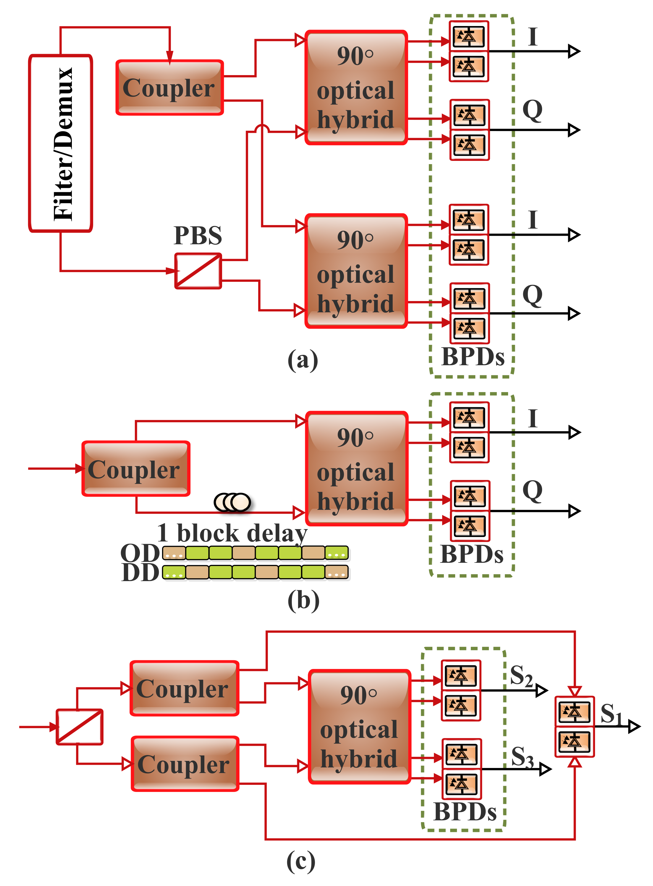
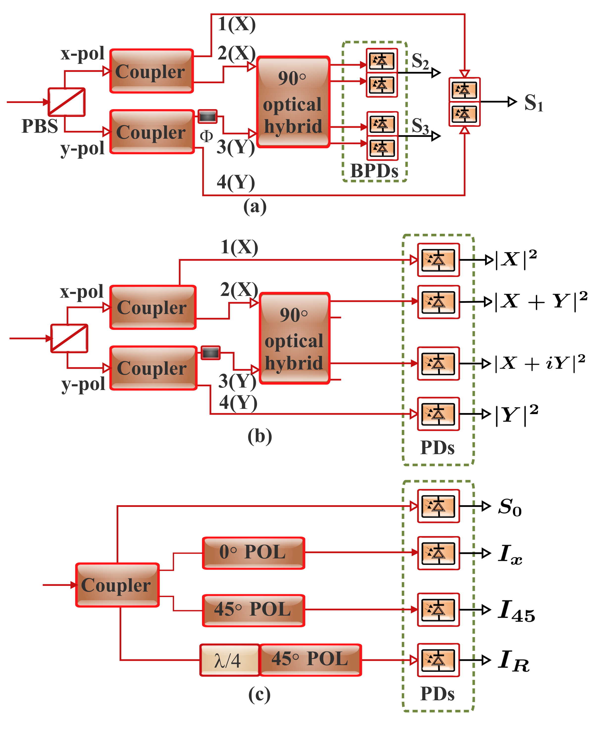
9.1. Polarization Recovery Techniques in the Direct Detection Stokes Vector Receiver

As previously mentioned in Section 8, the system AIR can be enhanced by exploiting the polarization diversity feature of light [8]. Nonetheless, it is noteworthy that the optical signal polarization state changes randomly in the course of transmission. This is mainly owed to the dynamic and time-varying birefringence distribution along the length of the optical fiber link. This results in the random fluctuation of the Stokes parameters. Consequently, for effective signal recovery, the variation in the polarization state has to be tracked by the receiver. Moreover, in a typical COH detection system, a 4D (or 2D complex) detection is performed by the receiver in the Jones space. Then, the variation is usually characterized by a 2 × 2 Jones matrix. On the other hand, in a 3D Stokes space, a 3 × 3 real-valued rotation matrix can be used to represent the polarization rotation [8,13,24]. Furthermore, provided that the polarization mode dispersion and polarization-dependent loss (PDL) impacts are negligible, the rotation matrix is usually considered as a frequency-independent unitary matrix in the short-reach systems. There are a number of polarization recovery schemes such as the blind rotation matrix estimation algorithm and the training symbol-assisted rotation matrix estimation that can be employed in the rotation matrix estimation. Mainly, the schemes are contingent on factors such as the Stokes space modulation (SSM) format and the respective signal distribution in the Stokes space. In this subsection, the polarization recovery schemes are categorized based on the related Stokes space modulation formats [13].

9.1.1. Adaptive MIMO Equalization

An extensively employed polarization recovery technique for the PDM-COH systems is an adaptive MIMO equalization. Furthermore, to facilitate a linear-equalization-based polarization recovery in the Stokes space modulation systems with DD-SVR, the associated signals have to be linear to the Stokes parameters. For instance, a 3 × 2 MIMO equalizer is usually applied after Stokes vector detection in the PDM-PAM system. This helps the recovery of PAM signals that are modulated on the | X | 2 and | Y | 2 , which are analogous to S 0 and S 1 . Comparable with some 3D Stokes space modulation formats in which MIMO equalization is modified for the polarization recovery, the Stokes space signals can present a relaxed condition by being finite discrete values that can support digital equalization. Moreover, regarding the Stokes space field recovery, the SCOH-SSM is capable of employing a 3 × 2 equalizer for the polarization recovery. This is as a result of the complex signal that is linearly modulated on S 2 and S 3 [13].
An instance of adaptive equalization is the blind adaptive equalization (BA-E), which is another viable approach for tracking the polarization rotation in the SV-DD scheme [24,39,146]. As illustrated in Figure 20a, this can be realized through the simultaneous implementation of residual chromatic dispersion and other linear distortion compensations along with the complex signal development. The adaptive equalizer is based on the least mean squares algorithm. The three inputs (see Figure 20a) are to obtain the three components of the received Stokes vector [11]. The signal s ( k ) is the obtained output after polarization rotation, where k is the time index. The equalizer coefficients c 1 , c 2   and   c 3 are related to the rotation matrix inverse RM 1 as c n = h 2 n + j h 3 n ( n = 1 , 2 , 3 ) , where h m n denotes the matrix element of RM 1 of the mth row and nth column [24,39].
The procedures involved in the adaptive algorithm can be broadly classified into the steps depicted in Figure 21 [11,24,39]. The instantaneous squared error is minimized by the algorithm at new time k + 1 . Then, the filter coefficients’ deviation from the previous evaluation at time k is minimized as [11,24]:
min c ( k + 1 ) e ( k + 1 ) 2 + 1 / ( μ 1 ) R ( k + 1 ) 2 c ( k + 1 ) c ( k ) 2
Moreover, an experimental implementation of the algorithm for a single-carrier SV-DD was demonstrated in [39].

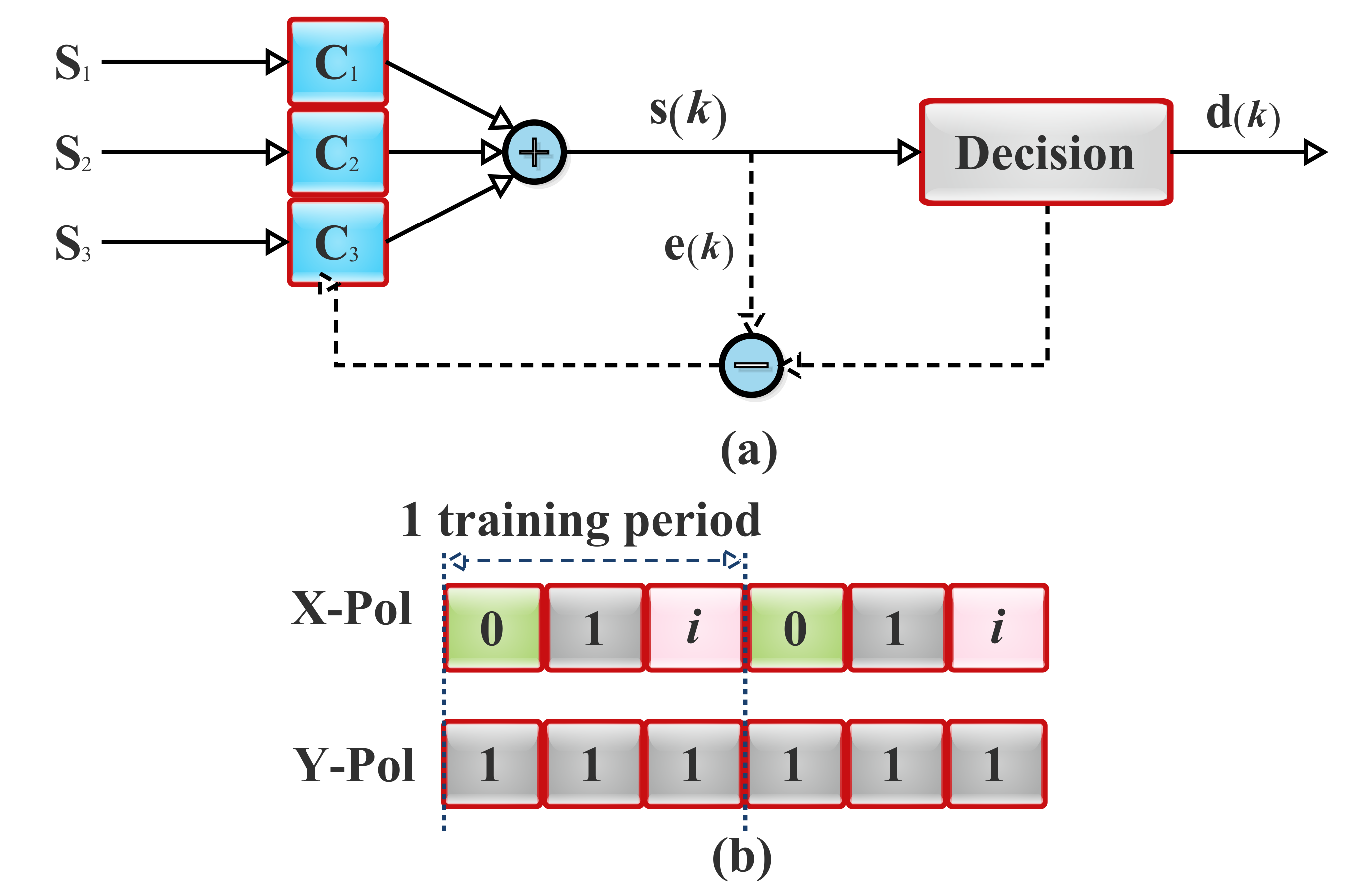
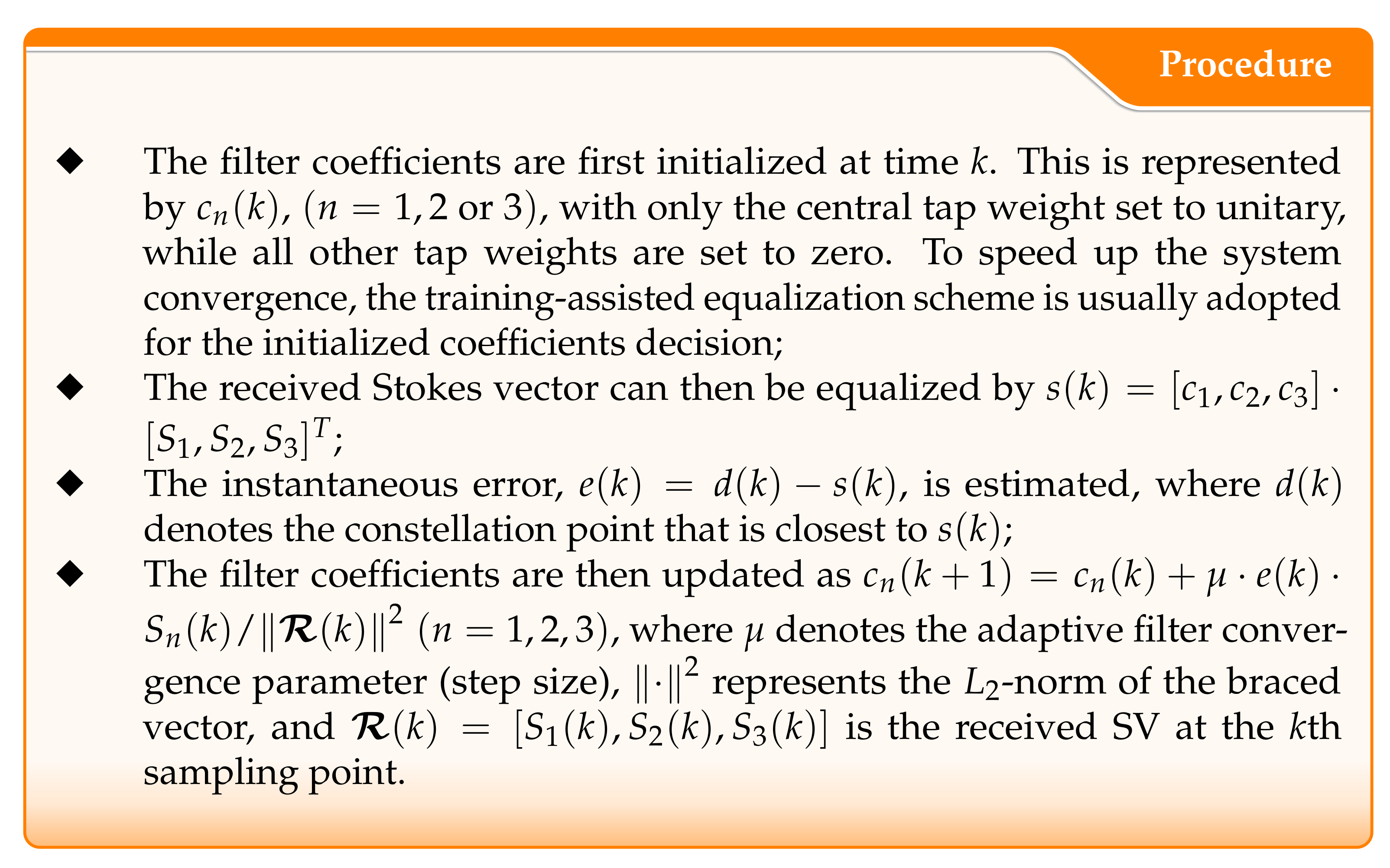
9.1.2. Training-Assisted Polarization Characterization

In a situation where the Stokes space signal distributions do not present discrete constellation information for the Stokes space modulation formats, certain special polarization training sequences have to be transmitted to facilitate the Stokes vector receiver in characterizing polarization variation. The three orthogonal bases in the Stokes space are the widely employed training sequences [8,13,24].
As depicted in Figure 20b, the training-assisted equalization (TA-E) scheme implementation entails the division of one training period into three time slots while the carrier power is kept constant. In this context, in the time domain, a specific training pattern can be appended before each frame of the signal. For instance, in the first time slot, while the carrier power is kept constant, no signal will be transmitted. Consequently, the Jones vector is for the slot 0 , 1 . Then, the corresponding Stokes vector for the Jones space representation of 0 , 1 is given as, 1 , 0 , 0 . Therefore, the received Stokes vector can be used to acquire the first column of the SV-RM in the first time slot as [8,24]:
S 1 S 2 S 3 = r 11 × × r 21 × × r 31 × × 1 0 0
where r i j denotes the rotation matrix element of the ith row and jth column.
In the second time slot, a real signal with constant power as that of the carrier can be transmitted. This gives rise to a Jones vector of 1 , 1 , and using the same approach discussed earlier, the Stokes vector of 0 , 1 , 0 will be obtained. Based on this, the second column of the SV-RM can be acquired. Furthermore, in the third time slot, the Jones vector of i , 1 resulting in the Stokes vector of 0 , 0 , 1 can be employed to acquire the third column of the SV-RM. Therefore, at the transmitter, three orthogonal training symbols with the Jones space representation 0 , 1 , 1 , 1 , and i , 1 with the three corresponding Stokes vector bases 1 , 0 , 0 , 0 , 1 , 0 , and 0 , 0 , 1 , respectively, are launched. It should be noted that the training symbols’ transmitted Stokes vector ( T ) and the training symbols’ received Stokes vector ( R ) are related by:
R = H · T ,
where H is the 3 × 3 rotation matrix in the Stokes space.
Therefore, the transmitted Stokes vector can be realized by multiplying the received Stokes vector with the inverse of the acquired rotation matrix as ( T = H 1 · R ) [8,24]:
X T 2 Y T 2 2 ( X T · Y T * ) 2 ( X T · Y T * ) = r 11 r 12 r 13 r 21 r 22 r 23 r 31 r 32 r 33 1 · X R 2 Y R 2 2 ( X R · Y R * ) 2 ( X R · Y R * )
where T and R denote the transmitter and receiver, respectively, and · 1 is the inverse operation.
Furthermore, based on the estimation of the Stokes vector rotation matrix ( H = R · T 1 ), the received signal Stokes vector can be recovered back to the transmitted polarization state as T = H 1 · R . Moreover, when a polarization division multiplexed signal is sent at the transmitter, the entire Stokes vector components will be the second order term of the signal, which results in a nonlinear channel response. Therefore, the signal will be considerably impaired through the spectrum power fading in the presence of the chromatic dispersion. This brings about a limited reach, owing to the fact that it will be highly challenging to transmit the signal over hundreds of kilometers. This challenge can be addressed by means of channel linearization. This can be achieved by maintaining the Y polarization as a constant carrier while the signal is used to modulate the X polarization only. Based on this approach, the subsequent Jones vector is J = [ X , Y ] T , and the Stokes vector can be defined as [24]:
S = | S | 2 | C | 2 , ( S · C * ) , ( S · C * ) T .
In general, the SV-DD algorithm concept is based on the combination of the second and the third components of the Stokes vector to achieve the final output S · C * , which contains the full phase diversity of the signal. Therefore, the signal can be fully recovered from the output without being marred by the chromatic dispersion-induced fading. Furthermore, the SV-DD algorithm helps associate the nonlinearity term with the first Stokes vector component without impairing the recovered signal derived from the second and the third Stokes vector components. Therefore, it is remarkable that the SV-DD signal is complex modulated, and there is no need for a frequency gap between the carrier and the signal. In this regard, the optical fiber channel can be considered as a linear complex optical channel that is comparable to that of COH detection [24]. As a result, compared with single-polarization-modulated COH detection, the SV-DD can realize 100% nominal SE. In relation to the offset-OFDM and VSSB, the SV-DD offers electrical spectrum efficiency of 4 × and 2 ×, respectively [8,13,24].
It is noteworthy that the implementation of the training-assisted equalization scheme imposes distinct conditions on the transmitter. For instance, there should be a symmetric power on the X- and Y- polarizations in the Jones space. It should be capable of controlling the interpolarization differential phase through its adjustment to 0 or 90 . Moreover, regarding the Stokes space field recovery, the PDM-SSB and SCOH-SSM can support and transmit the three required orthogonal bases [13].

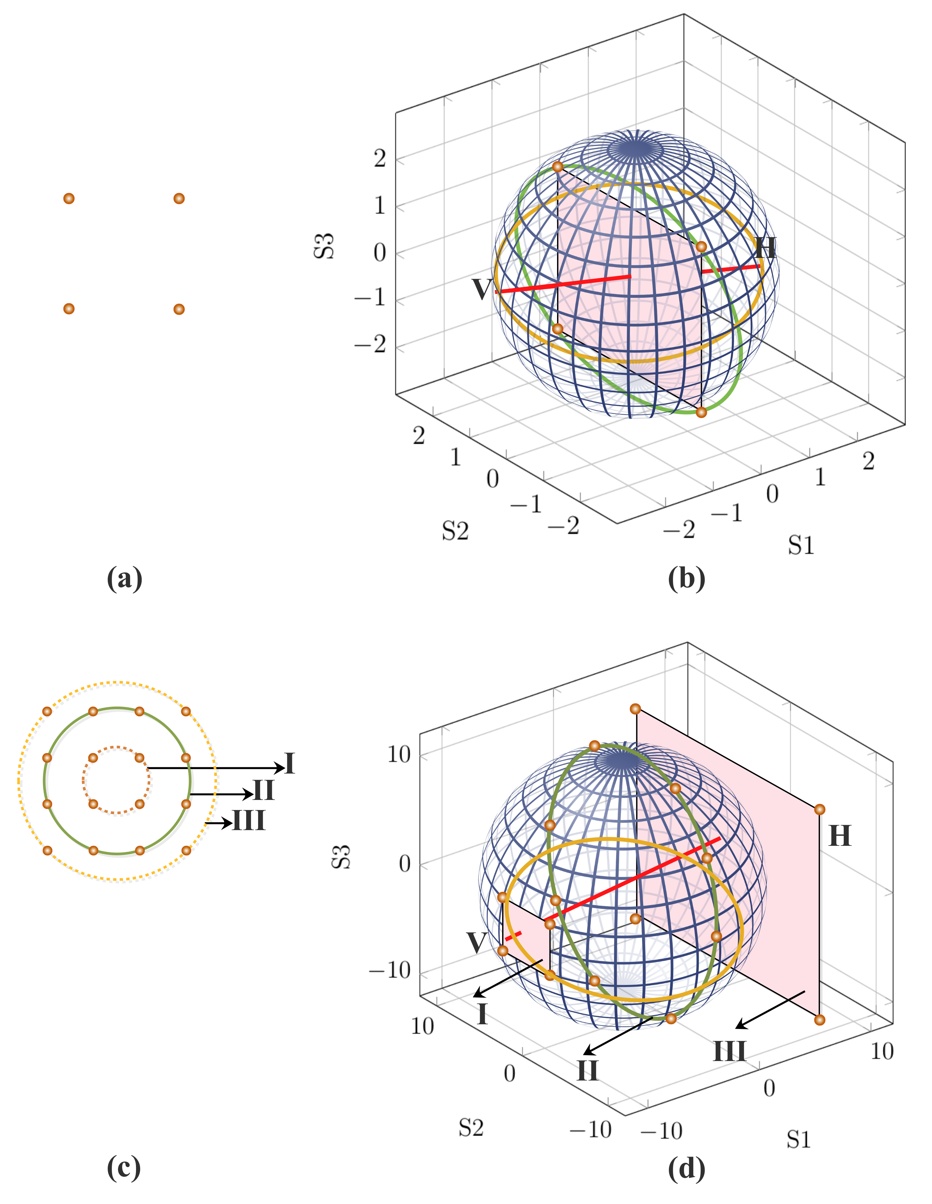
9.1.3. Stoke Space Signal-Distribution-Based Polarization Demultiplexing

Polarization rotation can also be ideally determined by neglecting the polarization-dependent loss and the polarization mode dispersion. In this context, two parameters between the two polarization modes, which are the phase difference, Δ ϕ , and the rotation angle, θ , have to be well considered. Through the received Stokes vector distribution analysis, Δ ϕ and θ can be obtained. Consequently, the 3 × 3 rotation matrix can be restored. For instance, for the 4-QAM modulation format shown in Figure 22a, a constant module is maintained by the signal. When the CSPR is set to 0 dB as illustrated in Figure 22b, the transmitted SVs can be restructured as: T = [ 0 , 2 S · C * , 2 ( S · C * ) ] T . With reference to the Poincaré sphere, all the SVs are positioned at the plane X = 0 with the normal given by ( 1 , 0 , 0 ) [11,23].
Furthermore, the received signal polarization state can be characterized by the plane and the associated normal vector. Furthermore, it is worth noting that there is a combination of the received SVs and the noise. This hinders their ability to completely fall into a plane. However, the least-squares plane (LSP) can be estimated for all the SVs. The least-squares plane is the plane that minimizes the value i ( d i ) 2 , where d i denotes the distance between the plane and the ith Stokes vector. Moreover, for the least-squares plane equation given as A x + B y + C z = 0 , the related least-squares plane normal vector would be ( A , B , C ) . d i between the SVs ( S i , 1 , S i , 2 , S i , 3 ) and the least-squares plane is given by [11]:
S 1 , 1 S 1 , 2 S 1 , 3 S 2 , 1 S 2 , 2 S 2 , 3 S n , 1 S n , 2 S n , 3 · A B C = d 1 d 2 d n .
In realistic scenarios, where the plane in the Stokes space suffers fast rotations induced by critical environmental conditions, affecting the fiber birefringence, the employment of alternative approaches for computing the normal vector may be advantageous [147]. In [148], the authors proposed an adaptive estimation of the inverse rotation matrix, without the calculation of the best fitting plane. This alternative method consists of an algorithm that uses the initial orientation of the normal, along with the polarization state of the upcoming signal sample, to adaptively compute the next normal. Moreover, the technique can integrate a stage for polarization-dependent loss compensation [149] without compromising its adaptive running [148].
It should be noted that one of the potential candidates for addressing the optimization problem is singular-value decomposition. Therefore, when the least-squares plane’s normal is estimated as N = ( n 1 , n 2 , n 3 ) , afterwards, the rotation angle and the phase delay can be expressed respectively as [11]:
θ = a tan n 2 2 + n 3 2 , n 1
Δ ϕ = a tan n 3 , n 2 .
Furthermore, the 3 × 3 rotation matrix can be obtained through multiplication of the polarization rotation matrix with the phase delay matrix as [11]:
R M = 1 0 0 0 cos ( Δ ϕ ) sin ( Δ ϕ ) 0 sin ( Δ ϕ ) cos ( Δ ϕ ) cos ( θ ) sin ( θ ) 0 sin ( θ ) cos ( θ ) 0 0 0 1 .
In addition, besides the 4-QAM, the aforementioned steps can be applied to other formats such as single-carrier modulations (i.e., 16-QAM) with discrete value modules and multicarrier modulation (i.e., OFDM) counterparts with arbitrary modules. For instance, a 16-QAM implementation with three modules and the SVs being partitioned into three groups is depicted in Figure 22c. Furthermore, when the CSPR is set to 0 dB, each of the Stokes vector groups will produce a plane in the Stokes space at the transmitter, as illustrated in Figure 22d. Consequently, by following the aforementioned processes for the 4-QAM, any group of points can be selected at the receiver to determine the least-squares plane and, subsequently, the rotation matrix. Moreover, it should be noted that within each of the planes, the Stokes vector power (i.e., S 0 ) is maintained to be the same [11].

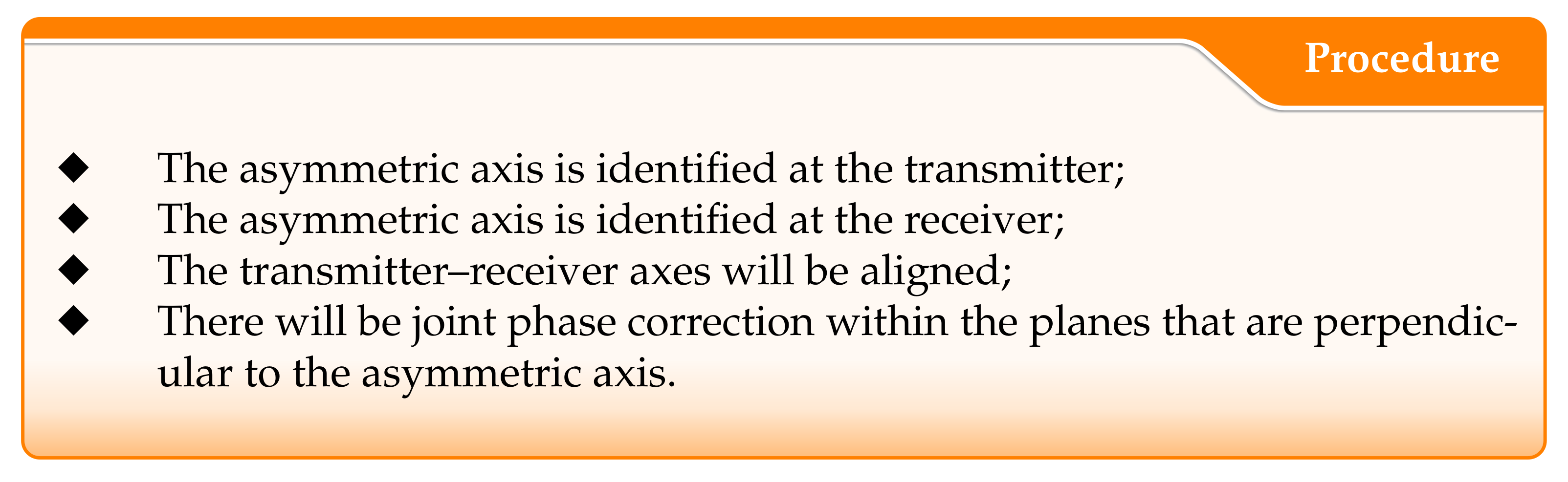
9.1.4. Analog Polarization Identification

As previously mentioned, when no discrete constellation information is presented, some training-assisted polarization characterization is required. However, the requirement of the three polarization bases’ transmission in the Stokes space might be a daunting task for the transmitter. A good instance of such scenarios is the implementation of the 3D Stokes space field recovery. In this case, irrespective of the adopted 1D field recovery scheme for the X-POL, a high CSPR is required either to guarantee a positive intensity envelope or reduce the SSBN power ratio. Consequently, the X-POL will possess a relatively higher power compared with the Y-POL, which results in an asymmetric distribution in the Stokes space. In such a condition, the associated signal will be intensely polarized towards X-POL. Based on this, the basis vector by the S 1 axis only can be transmitted [13].
Moreover, based on the asymmetric feature of polarization modulations, polarization axis identification is easy and digital signal knowledge is not required. Consequently, all-analog polarization recovery can be realized [13,150]. The concept has been presented for the DSP-free COH systems’ polarization recovery. In the implementation, to label the polarization state, a marker tone is appended to one polarization. It is noteworthy that the initial effort of analog polarization identification (API) in the Stokes space centers on the SCOH-SSM. In this, there is a constant carrier on the Y-POL that brings about a distribution in which the central axis orientation is towards the S 1 axis [13]. Furthermore, if the signal distribution in the Stokes space is asymmetric, then the analog polarization identification is a polarization recovery algorithm that is modulation independent. The procedure for the Stokes space analog polarization identification realization is shown in Figure 23.
A notable impact of the analog polarization identification is that digital clock recovery is not required by the polarization recovery. For instance, the average power S 1 of the 3D Stokes space modulation and the SCOH-SSM distribution are not dependent on proper digital sampling. Consequently, asymmetric axis identification can be realized in either the digital domain or analog domain through any sampling frequency mismatch. Moreover, the realization of polarization recovery ahead of clock recovery offers notable advantages. One is that the Stokes-space-modulated signal clock recovery can be simplified. Apart from the fact that the Stokes vector receiver will demand less DSP, it can also be DSP-free. This will eventually result in a receiver with relatively lower power consumption [13,150].

9.2. Stokes Space Field Recovery

As previously mentioned, the main aim of Stokes space field recovery is to offer an appropriate connection between the Jones space optical field and the Stokes space optical intensity in order to address the second-order nonlinear signal representation [13]. In this section, the digital subsystem dimension that comprises modulation and detection is defined in accordance with the bandwidth utilization of a band-limited receiver rather than the optical spectrum. Furthermore, the reference point for this analysis is the 1D subsystem with the IM-DD. Furthermore, it is remarkable that the SSB subsystem with complex modulation is commonly considered as 2D in the optical domain, at most; it recovers the B-baud complex signal with the B-Hz bandwidth. This is mainly owed to its heterodyne-based detection nature. Consequently, it can be considered as 1D in relation to the 1D IM-DD reference point. Moreover, a polarization division multiplexed COH system is a 4D-based scheme due to the fact that, with homodyne detection, a B-Hz dual-polarized Co-Rx can recover the maximum of a 2B-baud complex signal. This is equivalent to 4B-baud single-polarization. In addition, it should be noted that the Stokes vector receiver is capable of recovering any signal being modulated in the Stokes space. For instance, the Stokes vector elements can be modulated and subsequently detected in the Stokes space [11].

9.2.1. 1D Direct Detection-Based Field Recovery

As previously mentioned, field recovery is of paramount importance for system performance improvement. The complex signal field can be recovered merely from its intensity by modulating it with the SSB. In this regard, the optical carrier, C, is normally inserted along with the complex signal S ( t ) . Though it can be introduced away from the signal spectrum, to maximize the SE, it is usually located at the edge of the signal spectrum. Based on this, the SSB signal, U ( t ) = S ( t ) + C , I / Q parts are related by the Hilbert transform, H as [13]:
U Q ( t ) = H [ U I ( t ) ]
It is worth noting that the main associated limitation of the transformed signal is that it is challenging for the square law detection to recover a pure I part of the SSB signal. This is due to the second-order SSBN that contaminates the signal. This can be inhibited through the employment of a high CSPR, as well as several digital SSBN cancellation techniques [13,40]. Moreover, the relationship between the intensity, I ( t ) = | U ( t ) | 2 , and the phase, φ ( t ) , can be expressed in polar coordinates as [13]:
φ ( t ) = 1 / 2 · H [ log I ( t ) ] .
In addition, the 1D direct detection is also capable of recovering a DSB complex signal when a time domain redundancy is employed. This can be realized by means of the blockwise phase switching scheme discussed in Section 7.3.1. This approach is known as a carrier-assisted dual-polarized (CA-DP) modulation system with the SV-DD. In the CA-DP SV-DD system, two consecutive time domain signal blocks, S and i S , are forwarded by the blockwise phase switching transmitter [41]. Therefore, the carrier consecutively beats with the signal blocks for the I / Q parts, respectively, yielding [13,41]:
I = | S + C | 2 = | S | 2 + 2 ( S C * ) + | C | 2
Q = | i S + C | 2 = | S | 2 + 2 ( S C * ) + | C | 2 ,
where i denotes a 90 phase shift (switched).
It is noteworthy that the SSBN cancellation algorithm is still required by the blockwise phase switching receiver for the appropriate removal of the second-order terms. In relation to the SSB-FR, the BPS-FR can realize the same receiver electrical spectrum efficiency, but halves the optical spectrum efficiency as the SSB-FR [13].

9.2.2. 2D Direct-Detection-Based Field Recovery

The 2D direct-detection-based field recovery can be based on an SCOH Stokes space modulation (SCOH-SSM) or PDM-SSB modulation. The associated concept of these 2D direct-detection-based field recoveries is presented in this subsection.

Self-Coherent Stokes Space Modulation

As previously mentioned, the Stokes parameters are second-order terms of the field signal X and Y. Furthermore, the four Stokes parameters can be classified into two groups. The first group contains S 0 and S 1 , which are the self-beating of X and Y. Similarly, the second group comprises S 2 and S 3 , which are the cross-beating between X and Y [13]. Nevertheless, in order to linearize the direct detection optical channel, it is highly desirable to modulate the X polarization only with a complex DSB signal, while the Y polarization is launched as a constant carrier. The process helps ensure that the cross-beating terms are directly linearized. Consequently, after polarization rotation, the linear replica of X (a phase diverse signal) can be promptly recovered from S 2 + i S 3 = S · C * by the Stokes vector receiver. This is comparable to the output that can be realized by COH detection [11,13].

Polarization Division Multiplexing Single-Sideband Modulations

The SSB-FR exploits the corresponding double receiver bandwidth to convert a complex signal into an intensity signal after the square law detection. In this process, | U | 2 is transformed into U. For the PDM-SSB scheme, the dual-polarized optical field can be recovered by the SSB modulation of both polarizations. Consequently, after Stokes space polarization rotation, the field can then be recovered from S 0 and S 1 (i.e., | X | 2 and | Y | 2 ) [13].
Moreover, the PDM-SSB can be adapted by omitting the carrier at the Y-POL. With this approach, about a 3 dB carrier power at the transmitter can be conserved. Based on this, the system OSNR sensitivity can be improved. The implementation is known as PDM-SSB no-carrier Y-POL (PDM-SSB-NCY). Conceptually, rather than being retrieved from | Y | 2 , the field signal, Y, is retrieved from [ S 2 S 3 ] based on procedures that are similar to those of the 3D Stokes space field recovery as discussed in the following subsection [13].
In relation to the PDM-COH systems, the SCOH-SSM can attain 50% optical spectrum efficiency and electrical spectrum efficiency owing to the unmodulated Y-POL. However, with the PDM-SSB, the assessment is not straightforward. This is due to the fact that it is the direct detection system that is capable of recovering the dual-polarized optical field, and based on this, the optical spectrum efficiency is maximized to 100%. Nevertheless, being a 2D format in the Stokes space, only 50% electrical spectrum efficiency can be realized as the required receiver bandwidth is doubled by the SSB detection [13].
Furthermore, it is remarkable that, unlike the long-haul transmission in which high optical spectrum efficiency is usually taken into consideration in order to maximize the fiber capacity, in the short-reach applications, the primary consideration is electrical spectrum efficiency instead of optical spectrum efficiency. This is owed to the fact that the AIR per wavelength can be maximized by high electrical spectrum efficiency for a band-limited transceiver. This helps lessen the cost per bit and consequently results in transceiver cost reduction. In the short-reach networks that are deployed for commercial purposes, the optical spectrum resource is not a scarce commodity. Consequently, it is highly essential to focus on the electrical spectrum efficiency maximization in the 3D Stokes space field recovery system design [13,20].

9.2.3. 3D Direct-Detection-Based Field Recovery

As the Stokes space supports three distinct degrees of freedom for modulation, the 3D clock has been extensively investigated in an effort to maximize the Stokes vector receiver electrical spectrum efficiency. Basically, a conventional 3D clock comprises one interpolarization differential phase modulator and two IMs for dual-polarized optical intensities. Nevertheless, the 3D clock subsystems are not capable of recovering the whole set of fields for the three possible dimensions. Based on this, the attainable reach of the 3D clock subsystems is limited at the C-band when chromatic dispersion precompensation is not implemented. A notable way of addressing the challenge so as to ensure field recovery at the receiver is to perform linear complex modulations in the Jones space. It should be noted that due to the limitation being presented by the 3D modulation in the Stokes space, the dimension of one polarization in the Jones space has to be reduced to 1D and then the 1D field recovery exploited. This can be achieved by modulating the X-POL with a 1D signal, which can either be an SSB signal or a DSB signal with blockwise phase switching. On the other hand, the Y-POL can be a 2D DSB complex signal. Subsequently, the entire 3D field can be retrieved by the Stokes space field recovery after polarization rotation based on the following steps [13]:
  • The intensity X 2 = ( S 0 + S 1 ) / 2 can be recovered, and subsequently, the field X can be retrieved from the intensity information using 1D field recovery;
  • Furthermore, the field Y = ( S 2 + i S 3 ) * / X * can then be retrieved.
Although all the 3D Stokes space field recovery schemes employ the aforementioned procedures for retrieving all 3D fields, the main difference between them can be perceived from the adopted 1D field recovery method. For instance, there is a stringent impact on the SNR with SSB signal polarization employment because of the noise folding effect in the sideband of interest. This results in about a 3 dB OSNR penalty for the SSB-FR when the noise from the unoccupied sideband is folded into the utilized one after the square law detection. It should also be noted that the effect will also impact the other polarization. On the other hand, with the BPS-FR scheme implementation, DSB signals are modulated on both polarizations. This helps address the aforementioned penalty and related challenges of the SSB-FR [13].
Moreover, when the 1D systems such as the SSB-FR and BPS-FR that require SSBN cancellation at the X-POL are employed, then the field recovery depends on digital demodulation. However, the associated bit-error can impact the Y-POL field recovery. On the other hand, the related error propagation can be avoided by the SSB-FR. This can be achieved through direct signal phase reconstruction from the photocurrent in the polar coordinates [13].
In addition, the optical spectrum efficiency is halved by the BPS-FR in the 1D field recovery system compared with the SSB-FR. Nevertheless, when a 3D Stokes space field recovery scheme is implemented with either the BPS-FR or SSB-FR at the X-POL, the same optical spectrum efficiency will be achieved. This is a result of the unused sideband at the X-POL that is really challenging to share with another WDM channel since DSB modulation is implemented at the Y-POL. Moreover, with respect to the 4D PDM-COH systems, 75% optical spectrum efficiency can be achieved by the 3D Stokes space field recovery, and the electrical spectrum efficiency can be maximized to 75% as well. This value is the highest realizable electrical spectrum efficiency currently offered by the direct-detection-based receivers [13]. The related features of different dimensional detection field recovery schemes are presented in Table 10.
In general, the ability of a 1D direct detection scheme to recover a single-polarization-based optical field in the Jones space can be enhanced by duplicating the 1D field recovery scheme to realize a DP-FR system. Furthermore, it will be appropriate to detect only two intensities of | X | 2 and | Y | 2 (i.e., S 0 and S 1 ) that are expressed by the local polarization axes. Furthermore, the field X and Y can be recovered by means of the intensities. Then, the Jones space 2 × 2 MIMO polarization rotation can be implemented. Nevertheless, the related carrier fading is the primary impediment of the approach [13].
It is noteworthy that the optical carrier polarization state is unknown at the receiver when it travels along with the signal. Consistent separation of the carrier to the two local polarization axes might be challenging for the receiver. Therefore, the process can give rise to a total carrier fading at one of the polarization. Moreover, it has been observed that an active polarization control is required in the optical domain for the conventional PDM-SSB direct detection systems. A notable solution for addressing this in the offset-SSB is to launch two carriers, but at different frequencies so as to prevent destructive interference. In this, rather than the 2 × 2 (in view of two carriers and two polarizations at the receiver), 4 × 4 MIMO that is cascaded after field recovery for polarization recovery is employed. Furthermore, regarding the gapless SSB, there is no general consensus on whether the field recovery has to be implemented first before polarization recovery. However, the following points are very imperative in the system design:
  • The polarization recovery demands field recovery in the Jones space;
  • The gapless SSB-FR implementation demands a specified CSPR threshold;
  • Furthermore, in a condition whereby the polarization states are arbitrary, it will be highly challenging to guarantee the CSPR beyond the threshold for the entire MIMO dimensions without the polarization recovery.
Therefore, this results in unstable system performance for various polarization states. The issue can be prevented using the Stokes space. This is mainly due to it being isomorphic to the Jones space. Based on this, it offers exceptional potential for polarization recovery in its specific space, and field recovery is not required before polarization recovery. As a result, its implementation provides a reliable solution based on which polarization-diversity DD-FR can be employed without the need for an active optical polarization control [13].

10. Experimental Implementations

There are a considerable number of groups that have implemented SV-DD- and KK-based schemes using different models. In this part, we consider some key experimental implementations. Based on this, we give a fair comparison between both schemes regarding the required CSPR value and the system complexity.
In general, regarding an optical amplifier noise-limited system, an SV-DD can effectively operate at 0 dB CSPR while other direct-detection-based schemes normally require a relatively higher CSPR value. For instance, Table 11 illustrates various direct-detection-based experimental implementations that are grouped into SV-DD- and KK-based schemes. It can be inferred that while most of the SV-DD-based demonstrations demand 0 dB CSPR for signal transmission over more than 100 km SSMF, the KK-based demonstrations require ∼ 8 to 12 dB. This outstanding advantage can be attributed to the fact that the SSBN can be entirely separated from the desired signal by the SV-DD scheme. In this context, the SV-DD-based scheme offers the most efficient approach for the SSBN cancellation with the lowest required OSNR. This can be achieved without sacrificing the electrical bandwidth. Nevertheless, a conventional SV-DD-based scheme implementation demands a higher number of components, resulting in a more complex receiver structure compared with other single-PD-based schemes. Consequently, the SV-DD-based scheme receiver complexity can present significant challenges regarding cost and power consumption. Based on this, modified SV-DD-based schemes with a fewer components are highly imperative [19,151]. In this regard, a self-heterodyne SV-DD (SH-SVD) scheme that is based on an SSB signal and requires fewer components was presented in [151]. In spite of the fact that the scheme can considerably reduce the associated receiver cost and power consumption compared with a three- or four-PD-based SV-DD scheme, the related increase in the required sampling rate and bandwidth is another concern.

11. Further Research Directions and Future Considerations

There have been considerable research efforts on the simplified optical transceivers as expatiated in the previous sections. Nevertheless, some research directions on simplified optical transceivers are still underexplored. This section focuses on research opportunities and associated technical challenges. In this context, as illustrated in Figure 24, advancement towards high-baud-rate transmission, PIC exploitation, and software-defined optical transmission will be discussed.

11.1. Advancement towards High-Baud-Rate Transmission

The future optical networks are envisaged to support a diverse bandwidth demand due to the persistent growth in the DCN traffic. In this regard, for the associated large traffic demand between the main nodes, the deployment of Tb/s transponders is anticipated. Furthermore, the smaller nodes can exploit a fraction of the Tb/s traffic without employing expensive Tb/s receivers. It should be noted that there has been significant improvement in the COH systems that are capable of supporting a single-channel 1 Tb/s transmission [131]. Moreover, the increase in the production and advancement in photonics integration has helped alleviate the associated high cost of COH transceivers [131,161]. With advanced DSP, these have contributed immensely to the improvement in the SE, AIR, speed, and flexibility of optical transmission [161,162]. Based on this, the COH detection system is now becoming an attractive solution for short-reach use cases that have been dominated by the direct detection counterpart.
In addition, for the direct-detection-based schemes to offer comparable performance to the COH system, there have been a number of innovative direct detection schemes that have been presented. However, as previously mentioned, the schemes usually demand relatively complex optical hardware just as the COH schemes. For instance, an I Q M is required for the KK detection and a Stokes vector receiver for a polarization-diversity direct detection [14,23,131]. In this context, only marginal transceiver cost differences are anticipated between both systems in the future.
As previously mentioned, there are various proposed direct-detection-based schemes such as the KK and SSBN iterative cancellation receivers that can perform optical field recovery. Nevertheless, these SCOH schemes are limited to the SSB modulation format. Consequently, they conspicuously lose half of the electrical spectrum efficiency compared with the DSB modulation. The generation of the SSB is always inefficient either in transmitter bandwidth or in power. For instance, it is susceptible to the noise folding issue, which demands a precise optical filter. This requirement considerably complicates the receiver design. Therefore, it is noteworthy that for the SCOH to be competitive with the COH, it needs to handle the DSB. In this regard, all the SSB formats could potentially become just bookish discussions. Just as the heterodyne that has been extensively discussed in the lab, it has never been deployed largely in the field, due to the inferior electrical spectrum efficiency. Consequently, one research direction for the SCOH would be schemes that can detect the DSB rather than the well-studied and focused SSB. In this context, a notable and novel receiver scheme that can accomplish optical field recovery of complex-valued DSB signals through direct detection is carrier-assisted differential detection (CADD). Compared with the KK and SSBN iterative cancellation receivers, CADD doubles the electrical spectrum efficiency through the adoption of the DSB modulation without sacrificing the receiver sensitivity. By leveraging the direct detection in which a precise receiver optical filter is unnecessary, CADD can adopt cost-effective uncooled lasers in contrast to the expensive temperature-controlled lasers in the COH systems. As a result, the CADD receiver architecture initiates a new category of direct-detection-based schemes that are appropriate for photonic integration. This is comparable to the homodyne receivers in the COH detection [163,164].
In general, one of the effective means of minimizing the operational cost of a direct-detection-based scheme is to maximize the related reception rate per channel under the receiver bandwidth constraint. Therefore, an essential factor to be considered is the receiver bandwidth efficiency which is the ratio of the achievable rate to the receiver bandwidth limit. It is noteworthy that promising direct-detection-based receivers capable of supporting short-reach systems with 100 Gb/s and beyond should support complex signals that are relatively easier for a high-baud-rate generation. It is highly imperative to support digital chromatic dispersion post-compensation for a considerable reach extension. Furthermore, optical time-division multiplexing (OTDM) can be employed for the Tb/s transmission. However, apart from the need for a precise timing alignment of the tributaries in the OTDM, high-order optical dispersion compensation that is relatively expensive is demanded. Based on these, its implementation for Tb/s transmission is debatable. On the other hand, optical OFDM offers better performance regarding the SE and receiver sensitivity. It is not only resilient to tributary timing alignment, but is also robust to polarization/channel dispersion. Therefore, a PDM-M-QAM-OFDM scheme is a good candidate for the envisaged Tb/s transmission [131].

11.2. Performance Optimization Issues of Short-Reach Transceivers

Usually, for the performance optimization of a transmission system, the employment of high-speed and high-order signals is desirable. This is also applicable to the short-reach systems that are based on low-cost and direct-detection-based transmitters. However, in the short-reach transmission system, the bandwidth of the transmitter and receiver is low and comparatively less than the Nyquist bandwidth of the signal. In this regard, the application of high-speed and high-order signals to low-cost optical transmitters and receivers will result in performance degradation. The degradation can be owed to factors such as bandwidth limitation and chromatic dispersion-induced channel fading. Based on this, advanced DSP schemes can be exploited for impairment compensation and performance improvement [165].
As previously mentioned, viable schemes such as SSB signaling and the KK method can be employed for chromatic dispersion mitigation by means of Rx-DSP. Furthermore, the nonideal performance of low-cost components regarding insufficient bandwidth can be addressed by different advanced DSP algorithms. For instance, the direct detection-faster than Nyquist (DD-FTN) scheme can attend to the narrowband filtering effects and can offer considerable performance improvement compared with the traditional linear equalization that is typically employed for the bandwidth limitation compensation of optical systems. This is owed to the related enhancement of in-band noise in the bandwidth-limited optical systems by the linear equalization, which can be mitigated through the post filter of direct detection-faster than Nyquist [165].
Furthermore, another viable approach for the narrowband filtering effect mitigation is spectrally efficient frequency division multiplexing (SEFDM). In SEFDM, the subcarriers are packed closer beyond the Nyquist limit in the frequency domain (compared with OFDM) to accomplish SE gains, while the orthogonality and receiver complexity are compromised [165]. Furthermore, the differentially modulated or index modulation concept can also be applied to the SEFDM scheme for mitigating intercarrier interference effects and realizing higher bandwidth efficiency [166,167].
In addition, the Volterra series-based nonlinear equalization (VNLE) can also be employed to address the nonideal features of low-cost components. There is a linear term and nonlinear terms in the Volterra series expansion. Therefore, the linear and nonlinear impairments can be compensated simultaneously. However, as a result of the tradeoff between the equalization performance and computation complexity, VNLEs are usually designed just for the equalization of the first linear, as well as second-order nonlinear impairments [165]. Furthermore, with the progress in parallel computation, machine learning (ML) has been gaining significant attention and has been employed for nonlinearity mitigation. Furthermore, a number of ML-based algorithms such as support vector machines (SVMs) and artificial neural networks (ANNs) have been implemented in optical communication [168,169]. In optical systems, the algorithms can be used for several purposes such as estimation, classification, performance monitoring, and failure prediction. An ANN has been considered as a suitable solution for mitigating nonlinear impairments in an optical communication system based on its capability to establish a complex nonlinear boundary between different classifications (e.g., input and output spaces) [169]. In this context, ANN-based nonlinear equalizer (NLE) can offer better system performance than the VNLE-based NLE [170]. Nevertheless, the critical issue of an ANN implementation is the associated computational complexity [168]. A transfer-learning-aided NN-based nonlinear equalization can be employed to alleviate the associated issue of the ANN-based equalization [171].
Moreover, it should be noted that most of the schemes such as nonlinear Volterra equalizations and decision feedback equalizations that are based on advanced DSP for handling the impairments are usually applied at the receiver, and they require relatively high computational complexity. On the other hand, training-based pre-equalization (Pre-EQ) and nonlinear look-up-table (LUT) predistortion (Pre-DT) can also be employed to address the issues [172]. These implementations offer a notable advantage regarding an effective reduction in the Rx-DSP complexity [103,165].

11.3. Energy-Efficient Interconnection

As previously mentioned, one of the key challenges in the DCN design is the associated energy consumption of the infrastructure. The employed optical technology in DCNs is predominantly a point-to-point communication among switches. This is achieved with the aid of optical fibers and transceivers. Usually, regarding the fiber, low-cost MMFs that are operating at 850 nm are employed, while for the optical transceivers, they are based on SFP technology. With this approach, for effective communication, it is essential for the optical transmitters to transform the packets into optical signals, while optical receivers have to convert the signal to the electrical domain. This is due to the fact that packet switching is executed by means of electronic switch fabrics. In light of this, for packet switching, a significant amount of energy is wasted in the process of O/E and electrical-to-optical (E/O) conversions not only at the transceiver modules, but also on the switch fabrics. Considerable latency is also incurred in the conversions process. Likewise, there is further latency aggravation because of electrical buffering that is required at the respective switch to address packet contention. To attend to these challenges in the DCNs, an all-optical interconnect in which switching can be entirely executed in the optical domain to prevent energy-intensive electrical switches’ implementation is a promising solution. In this context, it is desirable to replace both electrical and opaque networks with transparent all-optical networks [74].

11.4. Photonic Integrated Circuit Exploitation

The conventional Co-Rxs that are based on 90 optical hybrids usually present an issue regarding the distortion in the received I Q signals. This can be attributed to hardware impairments during the fabrication process. For instance, the amplitude imbalances may be owed either to phase-diversity networks, coupling mismatches, or PD responsivities. The imbalances can result in adjacent channel interference, constellation distortion, and common-mode-rejection-ratio (CMRR) degradation. Although it is possible to employ complex DSP algorithms for the partial mitigation of constellation distortion, the CMRR correction and nonideal filter effects reduction are very challenging with the conventional DSP-based algorithms. To address the associated challenges, PIC receivers in which 120 hybrids are leveraged could be potential candidates. This is owed to the related better bandwidth performance and chip size reduction with merely three single-ended detectors. Through a linear calibration process, the hardware impairments can be alleviated. This brings about virtually perfect received I / Q signals and enhanced CMRRs, which implies better performance. Furthermore, the energy consumption can be reduced and the DSP workload can be alleviated compared with relatively complex DSP techniques [173]. Furthermore, apart from its capability to support a dense number of ports, photonic integration can efficiently support component sharing. For instance, a number of integrated WDM lasers can collectively share thermoelectric cooling rather than one for each. This can really help address the challenges of a growing increase in the lane rate [16]. Furthermore, PIC will facilitate integrated transmitter and receiver structures. With the integration, the system cost and form factor will be considerably reduced. Apart from the fact that it will ease signal generation, the integration will also facilitate chromatic dispersion precompensation and WDM multiplexing [35]. Nevertheless, there are some design and technical challenges that are specific to PIC technologies. For instance, concerted efforts are required to address the associated issues regarding the yield, assembly, packaging, circuit modeling, thermal management, process compatibility, RF interface management, ecosystem development, on-chip elements’ optimization, and manufacturing [174].

11.5. Software-Defined Optical Transmission

As previously mentioned, there has been considerable advancement in the area of COH optical transceivers as there are high-capacity COH transceivers such as 100 Gb/s and 200 Gb/s that are commercially available. Semiconductor companies are relentlessly working on the application-specific integrated circuit (ASIC) development for 400 Gb/s and beyond transceivers [161,162,175]. It is noteworthy that the 100 Gb/s-based transmission systems are compatible with the 50 GHz ITU wavelength grid. However, bit rates that are more than 100 Gb/s may not fit into the fixed 50 GHz spectrum slots. Therefore, a flexible grid model is required to meet future bandwidth demands. [175].
In addition, the scalability and flexibility of most of the transceivers in certain operation scenarios such as SDN and flexible grid DWDM links are debatable [1,161,162,175]. It should be noted that optical technologies that leverage the SDN can help the realization and optimization of on-demand infrastructure and service provisioning to subscribers in an efficient manner [176]. This is mainly owed to the SDN inherent features such as centralized controllers, data plane open interfaces, the global network view, as well as separate data and control planes [176,177]. With native support for software-defined optical transmission by the transceiver, the system throughput and flexibility can be significantly improved [1,161,162,175]. For instance, optimal use of the transceiver can be achieved in some cases if it can be sliced into portions. In this regard, each portion can be dynamically used to support different applications in accordance with their respective need. In general, adaptive and flexible networks that are well equipped with flexible transceivers and network elements that are capable of adapting to the actual traffic needs are required to address the challenges appropriately [175]. This section focuses on research directions and considerations for software-defined optical transmission systems.

11.5.1. Software-Defined Optical Transceivers

There has been considerable migration from static networks that offer limited flexibility to software-defined optical networks (SDONs) by the telecommunications industry. The rationale behind the adaptation is due to the fact that the perpetual increase in traffic has to be supported by dynamic network throughput. The usable fiber bandwidth is limited, and an increase in the SE is at the expense of the achievable reach. Another challenge being faced by the telecommunications industry is the growing increase in the dynamic environment and the heterogeneous nature in the optical transport network (OTN) [1,161]. The variation can be attributed to an increase in the uncertainty of the traffic sources and the heterogeneity of the demands, as well as the ever-changing models being employed by the content providers to address them [175].
In addition, the optical network operators usually intend to accomplish the fairest possible optimal tradeoff between the SE and the reach. Consequently, for effective support of the network requirements in the SDON environment, the transceivers need to have good controls and adaptations for a number of parameters and functionalities that are related to the symbol rate, modulation format, FEC overhead, channel spacing, optical spectrum shaping, and coding gain (CG). In light of this, software-defined transceivers have been attracting significant attention due to the offered benefits such as improved flexibility, increased robustness to channel impairments, and an upgrade path for the content-aware future transmission systems. In this regard, they have been envisaged to play a significant function in dynamic access network development [178,179].
Based on the transceivers’ programmability and parameter adaptation, optimal tradeoffs among the reach, power dissipation, and data rate can be realized in accordance with the bandwidth requirements and prevailing channel conditions [161,162,178,180]. This will facilitate the ability of the transceivers to support “any-haul”. Therefore, the same transceiver can be employed for different applications through appropriate parameter reconfiguration, making it a promising candidate for SDON applications [161]. Furthermore, it is noteworthy that reconfigurable transceivers’ development will demand different innovations in both software and hardware parts that might be more demanding than the fixed counterparts. Similarly, network control and management could be more challenging [175].

11.5.2. Sliceable Transceivers

The increasing growth in traffic and its dynamic nature can be supported by deploying more network resources that are seemingly static. However, in a situation where the cost scales linearly with the required bandwidth, support for the new services might not be cost-effective. To address this, the optical spectrum has to be utilized efficiently. Therefore, with elastic optical networks (EONs) in conjunction with the required bandwidth variable reconfigurable optical add–drop multiplexers (ROADMs), as well as rate and/or reach adaptive (flexible) optical transponders, different transmission parameters such as the baud rates, bit rates, subcarriers, and modulation formats can be dynamically changed and aggregated [175,180,181]. Then, the transmission bandwidth can be sliced and software-controlled for a dynamic adaptation and simultaneous support of numerous independent traffic demands and optical reaches [161,181]. Some of such efforts are based on the adoption of VCSELs with a multicarrier scheme, flexible bandwidth wavelength selective switches, and dense photonic integration [182,183,184,185]. Furthermore, besides being able to address the dynamic increase in the traffic, the sliceable bandwidth variable transponder (S-BVT) applies to high rates of migration and network restoration. Nevertheless, intense and concerted research efforts are still on to realize transponders that are power- and cost-effective, to support the required features [181,186].
Furthermore, parallelization in optical transceiver design is ongoing mainly to address the limitation of an electrical bandwidth [181,186].

11.6. Software-Defined Modulation

It is noteworthy that the net data rate that can be achieved will only change in coarse discrete steps when a fixed symbol rate and a fixed-rate code scheme are employed. To address the coarse discrete steps’ change and realize a continuous tradeoff between the SE and reach while keeping the symbol rate fixed, a variable-rate FEC code and advanced modulation techniques can be employed [187]. Furthermore, the modulation format can be software-defined when the transmitter-site DSP and the collaborative receiver-side DSP are exploited. In this regard, the system performance can be optimized based on the link conditions. Besides the conventional square QAM, advanced modulation formats such as the 4D modulation formats and iterative polar modulation in which the four orthogonal dimensions are jointly exploited can be employed. In addition, the tolerance of the signal to nonlinear fiber transmission impairment and linear noise can be enhanced by means of an optimized 4D constellation shaping [162].
In addition, software-defined transceivers are evolving and have been attracting applications in long-haul optical networks. Furthermore, a number of access-network-based transceiver implementations that are capable of flexible exploitation of multiplexing schemes and modulation formats have been emerging [188]. In this regard, a number of software-defined transceivers have been experimentally demonstrated for access networks. For instance, a DSP-based DMT modulation for a 100 Gb/s/ λ IM-DD transmission over 10 km SMF by employing high-speed CMOS DAC technology has been demonstrated [189]. The demonstration demands fiber chromatic dispersion mitigation to extend the reach to 40 km. Furthermore, the benefits of software-defined OpenFlow1.0-based flex-grid λ -flow configuration for dynamic 150 Mb/s per-cell 4G OFDM transceivers in relation to the CPRI-based method for a high-speed, low-latency mobile backhaul were established over 20 km SSMF in [179]. The scheme can offer interoperable on-demand spectrum allocation by means of software-defined control.
In general, different transceiver and network architectures have been developed for short-reach applications. Owing to different hardware being demanded by each architectural implementation, there may be relatively different limitations that will be imposed on the level at which each configuration can exploit the software-based advantages. For instance, since different transceiver architectures’ modulation and detection techniques, as well as the offered DoF are diverse, some hardware implementations should be more promising than the others for short-reach-based software-defined transceiver applications [178]. In addition, the full integration of programmability and softwarization into the optical transceiver systems to exploit their intrinsic benefits demand sufficient information about the peculiarities of the related devices and elements to be programmed. Moreover, the potentials and the limitations of the associated photonic technologies have to be well known. In this context, the programmable and accessible parameters have to be understood. This will facilitate the definition of an information model to be implemented by the SDN controller for the effective configuration of the network elements and underlying devices [190]. Apart from the fact that more research attention has to be paid to reconfigurable transceivers, concerted efforts are still required to make the transceivers cost-effective enough for short-reach applications. Further information regarding the related design challenges and tradeoffs for practical optical transceiver implementations is given in [35,161] and the references therein.

12. Conclusions

The growing increase in the adoption of 5G-enabled mobile applications and services in the access and metropolitan networks is pushing the global IP traffic to the zettabytes range, making optical communication systems highly essential to support the growing demands. In optical communication systems, performance enhancement depends on how the physical dimensions such as time, frequency, quadrature, polarization, and space are being systematically exploited for modulating and multiplexing light. The information-theoretic capacity per unit bandwidth is the fundamental limit to spectral efficiency. A high delay and complexity can result from close proximity to such a limit. Furthermore, there is an associated complexity to the capacity that can be supported by different optical transceiver systems, with high-sensitivity and high-capacity 4D coherent being more complex than the low-capacity 1D intensity modulation with direct detection counterpart. The realization of polarization-independent operation for complexity minimization rather than polarization diversity presents considerable optical complexity. Consequently, to alleviate the related complexity, it is highly desirable to accomplish polarization-independent reception without the need for optical polarization tracking at the receiver. The self-coherent schemes are opening up new prospects for ultra-high-capacity transceivers. This presents remarkable advantages beyond the conventional intensity modulation with direct detection while still relatively maintaining the simplicity and salient cost-efficiency feature for short- and medium-reach applications. The offered benefits are as a result of the exploited advantages of the cost-effective and simplified intensity modulation with direct detection, as well as the high sensitivity and complex modulation format that enabled sophisticated coherent systems. Moreover, the great majority of the self-coherent schemes are polarization insensitive/independent, and they can perform up to 3D detection without the need for an LO, which eliminates the need for sophisticated remote wavelength management between the transmitter and the receiver. Based on their relative advantages, they are capable of supporting data rates beyond 100 G per wavelength at relatively longer transmission distances, making them a promising solution for high-bandwidth, low-footprint, high-performance, energy-efficient, and cost-sensitive short- and medium-reach applications. In this paper, we presented comprehensive tutorials on the main requirements, technologies, architectures, and associated challenges of different transceiver systems. Different advancements in modulation formats, devices, and digital signal processing algorithms that are capable of facilitating 100 Gb/s and beyond per wavelength were broadly reviewed. Furthermore, a set of self-coherent schemes was well reviewed and comprehensively compared. We presented different channel linearization techniques along with the associated technical challenges of their implementations for optical direct-detection-based schemes. Moreover, certain related open-ended issues were presented, and the proffered potential solutions were well examined. It can be established that based on the promising and significant progress, there is considerable prospect towards high-speed optical transceivers that are capable of fulfilling the current and future requirements. This can be attributed to the fact that the self-coherent schemes aim to bridge the performance gaps between the conventional coherent and intensity modulation with direct detection schemes. Furthermore, it is anticipated that they will soon pave the way toward standardization and industrial development.

Author Contributions

Conceptualization, I.A., R.P., W.S., A.P. and N.M.; methodology, I.A., R.P., N.S. and N.M.; software, I.A. and N.M.; validation, I.A., W.S., A.P. and N.M.; formal analysis, I.A., R.P., N.S., C.S., H.J., W.S., A.P. and N.M.; investigation, I.A., R.P., N.S., C.S., H.J., W.S., A.P. and N.M.; resources, I.A., W.S., A.P. and N.M.; data curation, I.A., R.P. and N.M.; writing—original draft preparation, I.A. and N.M.; writing—review and editing, I.A., R.P., N.S., C.S., H.J., W.S., A.P. and N.M.; visualization, I.A., R.P., C.S. and H.J.; project administration, I.A., W.S., A.P. and N.M.; funding acquisition, A.P. and N.M. All authors read and agreed to the published version of the manuscript.

Funding

This work is supported by the European Regional Development Fund (FEDER) and the Internationalization Operational Programme (COMPETE 2020) of the Portugal 2020 (P2020) framework, under the projects DSPMetroNet (POCI-01-0145-FEDER-029405) and UIDB/50008/2020-UIDP/50008/2020 (DigCORE).

Institutional Review Board Statement

Not applicable.

Informed Consent Statement

Not applicable.

Data Availability Statement

Not applicable.

Conflicts of Interest

The authors declare no conflict of interest.

References

  1. Alimi, I.A.; Teixeira, A.L.; Monteiro, P.P. Toward an Efficient C-RAN Optical Fronthaul for the Future Networks: A Tutorial on Technologies, Requirements, Challenges, and Solutions. IEEE Commun. Surv. Tutor. 2018, 20, 708–769. [Google Scholar] [CrossRef]
  2. Muga, N.J.; Patel, R.K.; Alimi, I.; Silva, N.A.; Pinto, A.N. Self-coherent optical detection for access and metro networks. In Proceedings of the 2019 International Conference on Transparent Optical Networks ICTON, Angers, France, 9–13 July 2019; pp. 1–4. [Google Scholar]
  3. Zhu, Y.; Yi, L.; Yang, B.; Huang, X.; Wey, J.S.; Ma, Z.; Hu, W. Comparative study of cost-effective coherent and direct detection schemes for 100 Gb/s/λ PON. IEEE/OSA J. Opt. Commun. Netw. 2020, 12, D36–D47. [Google Scholar] [CrossRef]
  4. Alimi, I.A.; Abdalla, A.M.; Olapade Mufutau, A.; Pereira Guiomar, F.; Otung, I.; Rodriguez, J.; Pereira Monteiro, P.; Teixeira, A.L. Energy Efficiency in the Cloud Radio Access Network (C-RAN) for 5G Mobile Networks. In Optical and Wireless Convergence for 5G Networks; John Wiley & Sons, Ltd.: Hoboken, NJ, USA, 2019; Chapter 11; pp. 225–248. [Google Scholar] [CrossRef]
  5. Alimi, I.; Shahpari, A.; Sousa, A.; Ferreira, R.; Monteiro, P.; Teixeira, A. Challenges and Opportunities of Optical Wireless Communication Technologies. In Optical Communication Technology; Pinho, P., Ed.; IntechOpen: Rijeka, Croatia, 2017; Chapter 2. [Google Scholar] [CrossRef] [Green Version]
  6. Balanici, M.; Pachnicke, S. Hybrid electro-optical intra-data center networks tailored for different traffic classes. IEEE/OSA J. Opt. Commun. Netw. 2018, 10, 889–901. [Google Scholar] [CrossRef]
  7. Erkılınç, M.S.; Lavery, D.; Shi, K.; Thomsen, B.C.; Killey, R.I.; Savory, S.J.; Bayvel, P. Comparison of Low Complexity Coherent Receivers for UDWDM-PONs (λ-to-the-User). J. Light. Technol. 2018, 36, 3453–3464. [Google Scholar] [CrossRef]
  8. Che, D.; Li, A.; Chen, X.; Hu, Q.; Wang, Y.; Shieh, W. Stokes vector direct detection for short-reach optical communication. Opt. Lett. 2014, 39, 3110–3113. [Google Scholar] [CrossRef] [PubMed]
  9. Che, D.; Chen, X.; Li, A.; Hu, Q.; Wang, Y.; Shieh, W. Optical Direct Detection for 100 G Short Reach Applications. In Proceedings of the 2014 Asia Communications and Photonics Conference (ACP), Shanghai, China, 11–14 November 2014; pp. 1–3. [Google Scholar]
  10. Kikuchi, K. Fundamentals of Coherent Optical Fiber Communications. J. Light. Technol. 2016, 34, 157–179. [Google Scholar] [CrossRef]
  11. Che, D.; Shieh, W. Polarization Demultiplexing for Stokes Vector Direct Detection. J. Light. Technol. 2016, 34, 754–760. [Google Scholar] [CrossRef]
  12. Che, D.; Hu, Q.; Shieh, W. Linearization of Direct Detection Optical Channels Using Self-Coherent Subsystems. J. Light. Technol. 2016, 34, 516–524. [Google Scholar] [CrossRef]
  13. Che, D.; Sun, C.; Shieh, W. Optical Field Recovery in Stokes Space. J. Light. Technol. 2019, 37, 451–460. [Google Scholar] [CrossRef]
  14. Morsy-Osman, M.; Plant, D.V. A Comparative Study of Technology Options for Next Generation Intra- and Inter-datacenter Interconnects. In Proceedings of the 2018 Optical Fiber Communications Conference and Exposition (OFC), San Diego, CA, USA, 11–15 March 2018; pp. 1–3. [Google Scholar]
  15. Altabas, J.A.; Suhr, L.F.; Valdecasa, G.S.; Lazaro, J.A.; Garces, I.; Jensen, J.B.; Clausen, A.T. 25 Gbps Quasicoherent Receiver for Beyond NG-PON2 Access Networks. In Proceedings of the 2018 European Conference on Optical Communication (ECOC), Roma, Italy, 23–27 September 2018; pp. 1–3. [Google Scholar] [CrossRef]
  16. Wei, J.; Cheng, Q.; Penty, R.V.; White, I.H.; Cunningham, D.G. 400 Gigabit Ethernet using advanced modulation formats: Performance, complexity, and power dissipation. IEEE Commun. Mag. 2015, 53, 182–189. [Google Scholar] [CrossRef]
  17. Chagnon, M. Optical Communications for Short Reach. J. Light. Technol. 2019, 37, 1779–1797. [Google Scholar] [CrossRef]
  18. Mecozzi, A.; Antonelli, C.; Shtaif, M. Kramers–Kronig coherent receiver. Optica 2016, 3, 1220–1227. [Google Scholar] [CrossRef]
  19. Chen, X.; Antonelli, C.; Chandrasekhar, S.; Raybon, G.; Mecozzi, A.; Shtaif, M.; Winzer, P. Kramers–Kronig Receivers for 100-km Datacenter Interconnects. J. Light. Technol. 2018, 36, 79–89. [Google Scholar] [CrossRef]
  20. Che, D.; Sun, C.; Shieh, W. Maximizing the spectral efficiency of Stokes vector receiver with optical field recovery. Opt. Express 2018, 26, 28976–28981. [Google Scholar] [CrossRef] [PubMed]
  21. Füllner, C.; Adib, M.M.H.; Wolf, S.; Kemal, J.N.; Freude, W.; Koos, C.; Randel, S. Complexity Analysis of the Kramers–Kronig Receiver. J. Light. Technol. 2019, 37, 4295–4307. [Google Scholar] [CrossRef]
  22. Li, Z.; Sezer Erkılınç, M.; Shi, K.; Sillekens, E.; Galdino, L.; Xu, T.; Thomsen, B.C.; Bayvel, P.; Killey, R.I. Digital Linearization of Direct-Detection Transceivers for Spectrally Efficient 100 Gb/s/λ WDM Metro Networking. J. Light. Technol. 2018, 36, 27–36. [Google Scholar] [CrossRef]
  23. Che, D.; Li, A.; Chen, X.; Hu, Q.; Wang, Y.; Shieh, W. 160-Gb/s stokes vector direct detection for short reach optical communication. In Proceedings of the OFC 2014, San Francisco, CA, USA, 9–13 March 2014; pp. 1–3. [Google Scholar] [CrossRef]
  24. Che, D.; Li, A.; Chen, X.; Hu, Q.; Wang, Y.; Shieh, W. Stokes Vector Direct Detection for Linear Complex Optical Channels. J. Light. Technol. 2015, 33, 678–684. [Google Scholar] [CrossRef]
  25. Morsy-Osman, M.; Chagnon, M.; Plant, D.V. Four-Dimensional Modulation and Stokes Direct Detection of Polarization Division Multiplexed Intensities, Inter Polarization Phase and Inter Polarization Differential Phase. J. Light. Technol. 2016, 34, 1585–1592. [Google Scholar] [CrossRef]
  26. Hoang, T.; Sowailem, M.; Zhuge, Q.; Osman, M.; Samani, A.; Paquet, C.; Paquet, S.; Woods, I.; Plant, D. Enabling High-Capacity Long-Reach Direct Detection Transmission With QAM-PAM Stokes Vector Modulation. J. Light. Technol. 2018, 36, 460–467. [Google Scholar] [CrossRef]
  27. Che, D.; Yuan, F.; Shieh, W. 200-Gb/s polarization-multiplexed DMT using stokes vector receiver with frequency-domain MIMO. In Proceedings of the 2017 Optical Fiber Communications Conference and Exhibition (OFC), Los Angeles, CA, USA, 19–23 March 2017; pp. 1–3. [Google Scholar]
  28. Presi, M.; Cossu, G.; Contestabile, G.; Ciaramella, E.; Antonelli, C.; Mecozzi, A.; Shtaif, M. Transmission in 125-km SMF with 3.9 bit/s/Hz Spectral Efficiency Using a Single-drive MZM and a Direct-detection Kramers–Kronig Receiver without Optical CD Compensation. In Proceedings of the 2018 Optical Fiber Communications Conference and Exposition (OFC), San Diego, CA, USA, 11–15 March 2018; pp. 1–3. [Google Scholar]
  29. Li, Z.; Erkılınç, M.S.; Shi, K.; Sillekens, E.; Galdino, L.; Thomsen, B.C.; Bayvel, P.; Killey, R.I. SSBI Mitigation and the Kramers–Kronig Scheme in Single-Sideband Direct-Detection Transmission With Receiver-Based Electronic Dispersion Compensation. J. Light. Technol. 2017, 35, 1887–1893. [Google Scholar] [CrossRef] [Green Version]
  30. Li, Z.; Erkilinç, M.S.; Shi, K.; Sillekens, E.; Galdino, L.; Thomsen, B.C.; Bayvel, P.; Killey, R.I. Joint Optimisation of Resampling Rate and Carrier-to-Signal Power Ratio in Direct-Detection Kramers–Kronig Receivers. In Proceedings of the 2017 European Conference on Optical Communication (ECOC), Gothenburg, Sweden, 17–21 September 2017; pp. 1–3. [Google Scholar] [CrossRef] [Green Version]
  31. Randel, S.; Pilori, D.; Chandrasekhar, S.; Raybon, G.; Winzer, P. 100-Gb/s discrete-multitone transmission over 80-km SSMF using single-sideband modulation with novel interference-cancellation scheme. In Proceedings of the 2015 European Conference on Optical Communication (ECOC), Valencia, Spain, 27 September–1 October 2015; pp. 1–3. [Google Scholar] [CrossRef]
  32. Altabas, J.A.; Izquierdo, D.; Lazaro, J.A.; Garces, I. Cost-Effective Transceiver Based on an RSOA and a VCSEL for Flexible uDWDM Networks. IEEE Photonics Technol. Lett. 2016, 28, 1111–1114. [Google Scholar] [CrossRef]
  33. Morsy-Osman, M.; Chagnon, M.; Poulin, M.; Lessard, S.; Plant, D.V. 1λ× 224 Gb/s 10 km transmission of polarization division multiplexed PAM-4 signals using 1.3 μm SiP intensity modulator and a direct-detection MIMO-based receiver. In Proceedings of the 2014 The European Conference on Optical Communication (ECOC), Cannes, France, 21–25 September 2014; pp. 1–3. [Google Scholar] [CrossRef]
  34. Chagnon, M.; Lessard, S.; Plant, D.V. 336 Gb/s in Direct Detection Below KP4 FEC Threshold for Intra Data Center Applications. IEEE Photonics Technol. Lett. 2016, 28, 2233–2236. [Google Scholar] [CrossRef]
  35. Zhong, K.; Zhou, X.; Huo, J.; Yu, C.; Lu, C.; Lau, A.P.T. Digital Signal Processing for Short-Reach Optical Communications: A Review of Current Technologies and Future Trends. J. Light. Technol. 2018, 36, 377–400. [Google Scholar] [CrossRef]
  36. Rasmussen, J.C.; Takahara, T.; Tanaka, T.; Kai, Y.; Nishihara, M.; Drenski, T.; Li, L.; Yan, W.; Tao, Z. Digital signal processing for short reach optical links. In Proceedings of the 2014 The European Conference on Optical Communication (ECOC), Cannes, France, 21–25 September 2014; pp. 1–3. [Google Scholar] [CrossRef]
  37. Hoang, T.; Sowailem, M.; Osman, M.; Paquet, C.; Paquet, S.; Woods, I.; Zhuge, Q.; Plant, D.V. 280-Gb/s 320-km transmission of polarization division multiplexed QAM-PAM with stokes vector receiver. In Proceedings of the 2017 Optical Fiber Communications Conference and Exhibition (OFC), Los Angeles, CA, USA, 19–23 March 2017; pp. 1–3. [Google Scholar]
  38. Shieh, W.; Che, D. Optical Field Recovery via Stokes Vector Direct Detection. In Proceedings of the 2019 Optical Fiber Communications Conference and Exhibition (OFC), San Diego, CA, USA, 3–7 March 2019; pp. 1–3. [Google Scholar]
  39. Li, A.; Che, D.; Chen, V.; Shieh, W. Spectrally efficient optical transmission based on Stokes vector direct detection. Opt. Express 2014, 22, 15662–15667. [Google Scholar] [CrossRef] [PubMed]
  40. Chen, X.; Li, A.; Che, D.; Hu, Q.; Wang, Y.; He, J.; Shieh, W. Block-wise phase switching for double-sideband direct detected optical OFDM signals. Opt. Express 2013, 21, 13436–13441. [Google Scholar] [CrossRef] [PubMed]
  41. Li, A.; Li, Z.; Wen, Y.; Peng, W.; Cui, Y.; Bai, Y. 192-Gb/s 160-km transmission of carrier-assisted dual- polarization signal with Stokes vector direct detection. In Proceedings of the 2016 Optical Fiber Communications Conference and Exhibition (OFC), Anaheim, CA, USA, 20–24 March 2016; pp. 1–3. [Google Scholar]
  42. Pang, X.; Ozolins, O.; Lin, R.; Zhang, L.; Udalcovs, A.; Xue, L.; Schatz, R.; Westergren, U.; Xiao, S.; Hu, W.; et al. 200 Gbps/Lane IM/DD Technologies for Short Reach Optical Interconnects. J. Light. Technol. 2020, 38, 492–503. [Google Scholar] [CrossRef] [Green Version]
  43. Mecozzi, A.; Antonelli, C.; Shtaif, M. Kramers–Kronig receivers. Adv. Opt. Photonics 2019, 11, 480–517. [Google Scholar] [CrossRef]
  44. Bo, T.; Kim, H. Toward Practical Kramers–Kronig Receiver: Resampling, Performance, and Implementation. J. Light. Technol. 2019, 37, 461–469. [Google Scholar] [CrossRef]
  45. Bo, T.; Kim, H. Kramers–Kronig Receiver Without Digital Upsampling. In Proceedings of the 2018 Optical Fiber Communications Conference and Exposition (OFC), San Diego, CA, USA, 11–15 March 2018; pp. 1–3. [Google Scholar]
  46. Bo, T.; Kim, H. Kramers–Kronig receiver operable without digital upsampling. Opt. Express 2018, 26, 13810–13818. [Google Scholar] [CrossRef]
  47. Kahn, J.M.; Ho, K. Spectral efficiency limits and modulation/detection techniques for DWDM systems. IEEE J. Sel. Top. Quantum Electron. 2004, 10, 259–272. [Google Scholar] [CrossRef] [Green Version]
  48. An, S.; Zhu, Q.; Li, J.; Su, Y. Accurate Field Reconstruction at Low CSPR Condition Based on a Modified KK Receiver with Direct Detection. J. Light. Technol. 2019, 1. [Google Scholar] [CrossRef]
  49. Blech, L.; Eldar, Y.; Antonelli, C.; Mecozzi, A.; Shtaif, M. The Enhanced Kramers Kronig Receiver. In Proceedings of the 2018 Optical Fiber Communications Conference and Exposition (OFC), San Diego, CA, USA, 11–15 March 2018; pp. 1–3. [Google Scholar]
  50. Lyu, M.; Shi, W.; Rusch, L.A. SiP Alternative to Enhanced KK for OFDM. In Proceedings of the 2018 European Conference on Optical Communication (ECOC), Roma, Italy, 23–27 September 2018; pp. 1–3. [Google Scholar] [CrossRef]
  51. Sun, C.; Che, D.; Ji, H.; Shieh, W. Towards Low Carrier-to-Signal Power Ratio for Kramers–Kronig Receiver. In Proceedings of the 2019 Optical Fiber Communications Conference and Exhibition (OFC), San Diego, CA, USA, 3–7 March 2019; pp. 1–3. [Google Scholar]
  52. An, S.; Zhu, Q.; Li, J.; Su, Y. Modified KK Receiver with Accurate Field Reconstruction at Low CSPR Condition. In Proceedings of the 2019 Optical Fiber Communications Conference and Exhibition (OFC), San Diego, CA, USA, 3–7 March 2019; pp. 1–3. [Google Scholar]
  53. Zhou, X.; Huo, J.; Zhong, K.; Khan, F.N.; Gui, T.; Zhang, H.; Tu, J.; Yuan, J.; Long, K.; Yu, C.; et al. Single Channel 50 Gbit/s Transmission Over 40 km SSMF Without Optical Amplification and In-Line Dispersion Compensation Using a Single-End PD-Based PDM-SSB-DMT System. IEEE Photonics J. 2017, 9, 1–11. [Google Scholar] [CrossRef]
  54. Zhu, Y.; Jiang, M.; Zhang, F. Direct detection of polarization multiplexed single sideband signals with orthogonal offset carriers. Opt. Express 2018, 26, 15887–15898. [Google Scholar] [CrossRef]
  55. Lu, D.; Zhou, X.; Huo, J.; Gao, J.; Yang, Y.; He, K.; Yuan, J.; Long, K.; Yu, C.; Lau, A.P.T.; et al. Theoretical CSPR Analysis and Performance Comparison for Four Single-Sideband Modulation Schemes With Kramers–Kronig Receiver. IEEE Access 2019, 7, 166257–166267. [Google Scholar] [CrossRef]
  56. Zhang, X.; Zhang, C.; Chen, C.; Jin, W.; Zhong, X.; Qiu, K. Digital chromatic dispersion pre-management for SSB modulation direct-detection optical transmission systems. Opt. Commun. 2018, 427, 551–556. [Google Scholar] [CrossRef]
  57. Le, S.T.; Schuh, K.; Dischler, R.; Buchali, F.; Schmalen, L.; Buelow, H. Beyond 400 Gb/s Direct Detection over 80km for Data Center Interconnect Applications. J. Light. Technol. 2019, 1. [Google Scholar] [CrossRef]
  58. Zou, K.; Zhu, Y.; Zhang, F.; Chen, Z. Spectrally efficient terabit optical transmission with Nyquist 64-QAM half-cycle subcarrier modulation and direct detection. Opt. Lett. 2016, 41, 2767–2770. [Google Scholar] [CrossRef] [PubMed]
  59. Li, Z.; Erkilinc, M.S.; Maher, R.; Galdino, L.; Shi, K.; Thomsen, B.C.; Bayvel, B.; Killey, R.I. Reach Enhancement for WDM Direct-Detection Subcarrier Modulation using Low-Complexity Two-Stage Signal-Signal Beat Interference Cancellation. In Proceedings of the ECOC 2016, 42nd European Conference on Optical Communication, Dusseldorf, Germany, 18–22 September 2016; pp. 1–3. [Google Scholar]
  60. Cano, I.N.; Lerin, A.; Polo, V.; Prat, J. Direct Phase Modulation DFBs for Cost-Effective ONU Transmitter in udWDM PONs. IEEE Photonics Technol. Lett. 2014, 26, 973–975. [Google Scholar] [CrossRef]
  61. Li, Z.; Erkılınç, M.S.; Shi, K.; Sillekens, E.; Galdino, L.; Xu, T.; Thomsen, B.C.; Bayvel, P.; Killey, R.I. Spectrally Efficient 168 Gb/s/λ WDM 64-QAM Single-Sideband Nyquist-Subcarrier Modulation With Kramers–Kronig Direct-Detection Receivers. J. Light. Technol. 2018, 36, 1340–1346. [Google Scholar] [CrossRef]
  62. Winterling, P. 100 Gigabit Ethernet—Fundamentals, Trends, and Measurement Requirements; White Paper; Viavi Solutions, Inc.: San Jose, CA, USA, 2015. [Google Scholar]
  63. Morsy-Osman, M.; Chagnon, M.; Poulin, M.; Lessard, S.; Plant, D.V. 224-Gb/s 10-km Transmission of PDM PAM-4 at 1.3 μm Using a Single Intensity-Modulated Laser and a Direct-Detection MIMO DSP-Based Receiver. J. Light. Technol. 2015, 33, 1417–1424. [Google Scholar] [CrossRef]
  64. Maniloff, E.; Gareau, S.; Moyer, M. 400 G and Beyond: Coherent Evolution to High-Capacity Inter Data Center Links. In Proceedings of the 2019 Optical Fiber Communications Conference and Exhibition (OFC), San Diego, CA, USA, 3–7 March 2019; pp. 1–3. [Google Scholar]
  65. Winzer, P.J. Beyond 100 G Ethernet. IEEE Commun. Mag. 2010, 48, 26–30. [Google Scholar] [CrossRef]
  66. Vernekar, A. Understanding 10G to 400 G Ethernet Speeds, Transceivers, and Selecting the Correct Fiber Optic Connectivity for Your Data Center; White Paper; AFL Hyperscale: Milton Keynes, UK, 2020. [Google Scholar]
  67. Cisco MDS 9000 Family Pluggable Transceivers; Data Sheet; Cisco: San Jose, CA, USA, 2017.
  68. Nokia. Mobile Transport Convergence Using Deterministic Time-Sensitive Networks. 2019. Available online: https://onestore.nokia.com/asset/206838 (accessed on 15 January 2021).
  69. Cisco. The Importance of Industrial Temperature Optics for Reliable Network Connectivity; White Paper; Cisco: San Jose, CA, USA, 2021. [Google Scholar]
  70. FiberStamp. Optical Transceivers Solution for 5G Fronthaul/Backhaul Bearer Network; Data Sheet; FiberStamp: Taiwan, China, 2020. [Google Scholar]
  71. FS. 400 G QSFP-DD; Data Sheet; FS: New Castle, DE, USA, 2020. [Google Scholar]
  72. Dayarathna, M.; Wen, Y.; Fan, R. Data Center Energy Consumption Modeling: A Survey. IEEE Commun. Surv. Tutorials 2016, 18, 732–794. [Google Scholar] [CrossRef]
  73. What Is a Data Center; White Paper; Cisco: San Jose, CA, USA, 2019.
  74. Kachris, C.; Kanonakis, K.; Tomkos, I. Optical interconnection networks in data centers: Recent trends and future challenges. IEEE Commun. Mag. 2013, 51, 39–45. [Google Scholar] [CrossRef]
  75. Ma, L.; Su, W.; Li, X.; Wu, B.; Jiang, X. Heterogeneous data backup against early warning disasters in geo-distributed data center networks. IEEE/OSA J. Opt. Commun. Netw. 2018, 10, 376–385. [Google Scholar] [CrossRef]
  76. Zhong, K.; Zhou, X.; Wang, Y.; Yu, C.; Lau, A.P.T.; Lu, C. Recent Advances for High Speed Data Center Inter-Connects. In Proceedings of the 2016 Asia Communications and Photonics Conference (ACP), Wuhan, China, 2–5 November 2016; pp. 1–3. [Google Scholar]
  77. Sun, L.; Du, J.; He, Z. Multiband Three-Dimensional Carrierless Amplitude Phase Modulation for Short Reach Optical Communications. J. Light. Technol. 2016, 34, 3103–3109. [Google Scholar] [CrossRef]
  78. Shieh, W.; Djordjevic, I. Chapter 11—OFDM Applications in Access Optical Networks. In OFDM for Optical Communications; Shieh, W., Djordjevic, I., Eds.; Academic Press: Oxford, UK, 2010; pp. 385–412. [Google Scholar] [CrossRef]
  79. Alimi, I.A. Demonstration of Effectiveness of OFDM for Mobile Communication Systems. Am. J. Mob. Syst. Appl. Serv. 2015, 1, 35–45. [Google Scholar]
  80. Alimi, I.A.; Popoola, J.J.; Akingbade, K.F.; Kolawole, M.O. Interference Management in MIMO-OFDM-Based Emerging Wireless Systems. Am. J. Inf. Sci. Comput. Eng. 2015, 1, 1–9. [Google Scholar]
  81. Che, D.; Shieh, W. Squeezing out the last few bits from band-limited channels with entropy loading. Opt. Express 2019, 27, 9321–9329. [Google Scholar] [CrossRef]
  82. Yekani, A.; Amiralizadeh, S.; Rusch, L.A. Analytical Study of Optical SSB-DMT With IMDD. J. Light. Technol. 2018, 36, 666–674. [Google Scholar] [CrossRef]
  83. Zhang, L.; Zuo, T.; Mao, Y.; Zhang, Q.; Zhou, E.; Liu, G.N.; Xu, X. Beyond 100-Gb/s Transmission Over 80-km SMF Using Direct-Detection SSB-DMT at C-Band. J. Light. Technol. 2016, 34, 723–729. [Google Scholar] [CrossRef]
  84. Shu, L.; Li, J.; Wan, Z.; Gao, F.; Fu, S.; Li, X.; Yang, Q.; Xu, K. Single-Lane 112-Gbit/s SSB-PAM4 Transmission With Dual-Drive MZM and Kramers–Kronig Detection Over 80-km SSMF. IEEE Photonics J. 2017, 9, 1–9. [Google Scholar] [CrossRef]
  85. Wan, Z.; Li, J.; Shu, L.; Fu, S.; Fan, Y.; Yin, F.; Zhou, Y.; Dai, Y.; Xu, K. 64-Gb/s SSB-PAM4 Transmission Over 120-km Dispersion-Uncompensated SSMF With Blind Nonlinear Equalization, Adaptive Noise-Whitening Postfilter and MLSD. J. Light. Technol. 2017, 35, 5193–5200. [Google Scholar] [CrossRef]
  86. Muller, M.; Hofmann, W.; Grundl, T.; Horn, M.; Wolf, P.; Nagel, R.D.; Ronneberg, E.; Bohm, G.; Bimberg, D.; Amann, M. 1550-nm High-Speed Short-Cavity VCSELs. IEEE J. Sel. Top. Quantum Electron. 2011, 17, 1158–1166. [Google Scholar] [CrossRef]
  87. Kapon, E.; Sirbu, A. Long-wavelength VCSELs: Power-efficient answer. Nat. Photonics 2009, 3, 27–29. [Google Scholar] [CrossRef]
  88. Xie, C.; Spiga, S.; Dong, P.; Winzer, P.; Gnauck, A.; Gréus, C.; Ortsiefer, M.; Neumeyr, C.; Müller, M.; Amann, M. Generation and transmission of 100-Gb/s PDM 4-PAM using directly modulated VCSELs and coherent detection. In Proceedings of the OFC 2014, San Francisco, CA, USA, 9–13 March 2014; pp. 1–3. [Google Scholar] [CrossRef]
  89. Moser, P.; Lott, J.A.; Wolf, P.; Larisch, G.; Li, H.; Bimberg, D. Error-free 46 Gbit/s operation of oxide-confined 980 nm VCSELs at 85 °C. Electron. Lett. 2014, 50, 1369–1371. [Google Scholar] [CrossRef]
  90. Chang, Y.; Coldren, L.A. Efficient, High-Data-Rate, Tapered Oxide-Aperture Vertical-Cavity Surface-Emitting Lasers. IEEE J. Sel. Top. Quantum Electron. 2009, 15, 704–715. [Google Scholar] [CrossRef]
  91. Spiga, S.; Soenen, W.; Andrejew, A.; Schoke, D.M.; Yin, X.; Bauwelinck, J.; Boehm, G.; Amann, M. Single-Mode High-Speed 1.5-μm VCSELs. J. Light. Technol. 2017, 35, 727–733. [Google Scholar] [CrossRef]
  92. Zhu, N.H.; Shi, Z.; Zhang, Z.K.; Zhang, Y.M.; Zou, C.W.; Zhao, Z.P.; Liu, Y.; Li, W.; Li, M. Directly Modulated Semiconductor Lasers. IEEE J. Sel. Top. Quantum Electron. 2018, 24, 1–19. [Google Scholar] [CrossRef]
  93. Xue, L.; Yi, L.; Ji, H.; Li, P.; Hu, W. Symmetric 100-Gb/s TWDM-PON in O-Band Based on 10G-Class Optical Devices Enabled by Dispersion-Supported Equalization. J. Light. Technol. 2018, 36, 580–586. [Google Scholar] [CrossRef]
  94. Jacques, M.; Samani, A.; Patel, D.; El-Fiky, E.; Morsy-Osman, M.; Hoang, T.; Saber, M.G.; Xu, L.; Sonkoly, J.; Ayliffe, M.; et al. Modulator material impact on chirp, DSP, and performance in coherent digital links: Comparison of the lithium niobate, indium phosphide, and silicon platforms. Opt. Express 2018, 26, 22471–22490. [Google Scholar] [CrossRef]
  95. Wang, C.; Zhang, M.; Stern, B.; Lipson, M.; Lončar, M. Nanophotonic lithium niobate electro-optic modulators. Opt. Express 2018, 26, 1547–1555. [Google Scholar] [CrossRef] [PubMed] [Green Version]
  96. Patel, D.; Samani, A.; Veerasubramanian, V.; Ghosh, S.; Plant, D.V. Silicon Photonic Segmented Modulator-Based Electro-Optic DAC for 100 Gb/s PAM-4 Generation. IEEE Photonics Technol. Lett. 2015, 27, 2433–2436. [Google Scholar] [CrossRef]
  97. Samani, A.; Patel, D.; Chagnon, M.; El-Fiky, E.; Li, R.; Jacques, M.; Abadía, N.; Veerasubramanian, V.; Plant, D.V. Experimental parametric study of 128 Gb/s PAM-4 transmission system using a multi-electrode silicon photonic Mach Zehnder modulator. Opt. Express 2017, 25, 13252–13262. [Google Scholar] [CrossRef] [PubMed]
  98. Cong, G.; Ohno, M.; Maegami, Y.; Okano, M.; Yamada, K. Silicon traveling-wave Mach–Zehnder modulator under distributed-bias driving. Opt. Lett. 2018, 43, 403–406. [Google Scholar] [CrossRef] [PubMed]
  99. Weigel, P.O.; Zhao, J.; Fang, K.; Al-Rubaye, H.; Trotter, D.; Hood, D.; Mudrick, J.; Dallo, C.; Pomerene, A.T.; Starbuck, A.L.; et al. Bonded thin film lithium niobate modulator on a silicon photonics platform exceeding 100 GHz 3-dB electrical modulation bandwidth. Opt. Express 2018, 26, 23728–23739. [Google Scholar] [CrossRef] [Green Version]
  100. Kimura, T. EML vs DML for Datacenter and Client Side Transceivers; Neophotonics Blog; NeoPhotonics: San Jose, CA, USA, 2015. [Google Scholar]
  101. Hasebe, K.; Matsuo, S.; Sanjoh, H.; Ohki, A.; Kakitsuka, T.; Shibata, Y. Directly frequency modulated DFB laser integrated with EA modulator for extended transmission reach. In Proceedings of the 36th European Conference and Exhibition on Optical Communication, Torino, Italy, 19–23 September 2010; pp. 1–3. [Google Scholar] [CrossRef]
  102. Verplaetse, M.; Lin, R.; Van Kerrebrouck, J.; Ozolins, O.; De Keulenaer, T.; Pang, X.; Pierco, R.; Vaernewyck, R.; Vyncke, A.; Schatz, R.; et al. Real-Time 100 Gb/s Transmission Using Three-Level Electrical Duobinary Modulation for Short-Reach Optical Interconnects. J. Light. Technol. 2017, 35, 1313–1319. [Google Scholar] [CrossRef]
  103. Zhang, J.; Yu, J.; Chien, H. EML-based IM/DD 400 G (4 × 112.5-Gbit/s) PAM-4 over 80 km SSMF based on linear pre-equalization and nonlinear LUT predistortion for inter-DCI applications. In Proceedings of the 2017 Optical Fiber Communications Conference and Exhibition (OFC), Los Angeles, CA, USA, 19–23 March 2017; pp. 1–3. [Google Scholar]
  104. Yao, X.S.; Maleki, L. Optoelectronic microwave oscillator. J. Opt. Soc. Am. B 1996, 13, 1725–1735. [Google Scholar] [CrossRef]
  105. Hao, T.; Liu, Y.; Tang, J.; Cen, Q.; Li, W.; Zhu, N.; Dai, Y.; Capmany, J.; Yao, J.; Li, M. Recent advances in optoelectronic oscillators. Adv. Photonics 2020, 2, 1–21. [Google Scholar] [CrossRef]
  106. 3Coptics. Optical Transceivers For 5G Networks. 2020. Available online: https://www.3coptics.com/News/9.html (accessed on 5 August 2021).
  107. Peng, W.R.; Wu, X.; Feng, K.M.; Arbab, V.R.; Shamee, B.; Yang, J.Y.; Christen, L.C.; Willner, A.E.; Chi, S. Spectrally efficient direct-detected OFDM transmission employing an iterative estimation and cancellation technique. Opt. Express 2009, 17, 9099–9111. [Google Scholar] [CrossRef] [Green Version]
  108. Schuster, M.; Randel, S.; Bunge, C.A.; Lee, S.C.J.; Breyer, F.; Spinnler, B.; Petermann, K. Spectrally Efficient Compatible Single-Sideband Modulation for OFDM Transmission With Direct Detection. IEEE Photonics Technol. Lett. 2008, 20, 670–672. [Google Scholar] [CrossRef]
  109. Zhu, Y.; Zou, K.; Ruan, X.; Zhang, F. Single Carrier 400 G Transmission With Single-Ended Heterodyne Detection. IEEE Photonics Technol. Lett. 2017, 29, 1788–1791. [Google Scholar] [CrossRef]
  110. Peng, W.; Morita, I.; Tanaka, H. Enabling high capacity direct-detection optical OFDM transmissions using beat interference cancellation receiver. In Proceedings of the 36th European Conference and Exhibition on Optical Communication, Torino, Italy, 19–23 September 2010; pp. 1–3. [Google Scholar] [CrossRef]
  111. Al-Qadi, M.; Vedala, G.; O’Sullivan, M.; Xie, C.; Hui, R. QD-MLL-Based Single-Sideband Superchannel Generation Scheme With Kramers–Kronig Direct Detection Receivers. IEEE Photonics J. 2019, 11, 1–13. [Google Scholar] [CrossRef]
  112. Roberts, K. Electronic Dispersion Compensation Beyond 10 Gb/s. In Proceedings of the 2007 Digest of the IEEE/LEOS Summer Topical Meetings, Portland, OR, USA, 23–25 July 2007; pp. 9–10. [Google Scholar] [CrossRef]
  113. Bulow, H.; Buchali, F.; Klekamp, A. Electronic Dispersion Compensation. J. Light. Technol. 2008, 26, 158–167. [Google Scholar] [CrossRef]
  114. Singer, A.C.; Shanbhag, N.R.; Bae, H. Electronic dispersion compensation. IEEE Signal Process. Mag. 2008, 25, 110–130. [Google Scholar] [CrossRef]
  115. Bulow, H. Tutorial Electronic Dispersion Compensation. In Proceedings of the OFC/NFOEC 2007—2007 Conference on Optical Fiber Communication and the National Fiber Optic Engineers Conference, Anaheim, CA, USA, 25–29 March 2007; pp. 1–25. [Google Scholar] [CrossRef]
  116. Savory, S.J.; Gavioli, G.; Killey, R.I.; Bayvel, P. Electronic compensation of chromatic dispersion using a digital coherent receiver. Opt. Express 2007, 15, 2120–2126. [Google Scholar] [CrossRef] [PubMed]
  117. Killey, R.I.; Watts, P.M.; Mikhailov, V.; Glick, M.; Bayvel, P. Electronic dispersion compensation by signal predistortion using digital Processing and a dual-drive Mach-Zehnder Modulator. IEEE Photonics Technol. Lett. 2005, 17, 714–716. [Google Scholar] [CrossRef]
  118. Peng, W.; Zhang, B.; Feng, K.; Wu, X.; Willner, A.E.; Chi, S. Spectrally Efficient Direct-Detected OFDM Transmission Incorporating a Tunable Frequency Gap and an Iterative Detection Techniques. J. Light. Technol. 2009, 27, 5723–5735. [Google Scholar] [CrossRef]
  119. Patel, R.K.; Alimi, I.; Muga, N.J.; Pinto, A.N. Optical Signal Phase Retrieval with Low Complexity DC-Value Method. J. Light. Technol. 2020, 38, 4205–4212. [Google Scholar] [CrossRef]
  120. Patel, R.K.; Guiomar, F.P.; Fernandes, M.A.; Alimi, I.A.; Monteiro, P.P.; Muga, N.J.; Pinto, A.N. Virtual Carrier Assisted Self-Coherent Detection Employing DC-Value Method. In Proceedings of the OSA Optical Fiber Communications—OFC, Washington, DC, USA, 6–11 June 2021. [Google Scholar]
  121. Chen, X.; Chandrasekhar, S.; Olsson, S.; Adamiecki, A.; Winzer, P. Impact of O/E Front-End Frequency Response on Kramers–Kronig Receivers and its Compensation. In Proceedings of the 2018 European Conference on Optical Communication (ECOC), Rome, Italy, 23–27 September 2018; pp. 1–3. [Google Scholar] [CrossRef]
  122. Ohlendorf, S.; Joy, R.; Pachnicke, S.; Rosenkranz, W. Flexible PAM in DWDM Transmission with Kramers–Kronig DSP. In Proceedings of the 2018 European Conference on Optical Communication (ECOC), Rome, Italy, 23–27 September 2018; pp. 1–3. [Google Scholar] [CrossRef]
  123. Schuh, K.; Le, S.T. 180 Gb/s 64QAM Transmission Over 480 km Using a DFB Laser and a Kramers–Kronig Receiver. In Proceedings of the 2018 European Conference on Optical Communication (ECOC), Rome, Italy, 23–25 September 2018; pp. 1–3. [Google Scholar] [CrossRef]
  124. Le, S.T.; Schuh, K.; Nguyen Tan, H. A Closed-Form Expression for Direct Detection Transmission Systems With Kramers–Kronig Receiver. IEEE Photonics Technol. Lett. 2018, 30, 2048–2051. [Google Scholar] [CrossRef]
  125. Sun, C.; Che, D.; Shieh, W. Comparison of Chromatic Dispersion Sensitivity between Kramers–Kronig and SSBI Iterative Cancellation Receiver. In Proceedings of the 2018 Optical Fiber Communications Conference and Exposition (OFC), San Diego, CA, USA, 11–15 March 2018; pp. 1–3. [Google Scholar]
  126. Sun, C.; Che, D.; Schmid, R.; Shieh, W. Polarization Mode Dispersion Impacts on Kramers–Kronig Receiver. In Proceedings of the 2018 23rd Opto-Electronics and Communications Conference (OECC), Jeju Island, Korea, 2–6 July 2018; pp. 1–2. [Google Scholar] [CrossRef]
  127. Bo, T.; Kim, H. Performance Analysis of Kramers–Kronig Receiver in the Presence of IQ Imbalance. IEEE Photonics Technol. Lett. 2018, 30, 2171–2174. [Google Scholar] [CrossRef]
  128. Chagnon, M.; Osman, M.; Patel, D.; Veerasubramanian, V.; Samani, A.; Plant, D.V. 1λ,6 bits/symbol, 280 and 350 Gb/s direct detection transceiver using intensity modulation, polarization multiplexing, and inter-polarization phase modulation. In Proceedings of the 2015 Optical Fiber Communications Conference and Exhibition (OFC), Los Angeles, CA, USA, 22–26 March 2015; pp. 1–3. [Google Scholar]
  129. Gui, T.; Wang, X.; Tang, M.; Yu, Y.; Lu, Y.; Li, L. Real-Time Demonstration of 600 Gb/s DP-64QAM Self-Homodyne Coherent Bi-Direction Transmission with Un-Cooled DFB Laser. In Proceedings of the 2020 Optical Fiber Communications Conference and Exhibition (OFC), San Diego, CA, USA, 8–12 March 2020; pp. 1–3. [Google Scholar]
  130. Sowailem, M.Y.S.; El-Fiky, E.; Morsy-Osman, M.; Zhuge, Q.; Hoang, T.M.; Paquet, S.; Paquet, C.; Woods, I.; Liboiron-Ladouceur, O.; Plant, D.V. Self-homodyne system for next generation intra-datacenter optical interconnects. Opt. Express 2017, 25, 27834–27844. [Google Scholar] [CrossRef]
  131. Che, D.; Chandrasekhar, S.; Chen, X.; Raybon, G.; Winzer, P.; Sun, C.; Shieh, W. Single-Channel Direct Detection Reception Beyond 1 Tb/s. In Proceedings of the 2019 Optical Fiber Communications Conference and Exhibition (OFC), San Diego, CA, USA, 3–7 March 2019; pp. 1–3. [Google Scholar]
  132. Savory, S.J. Digital Coherent Optical Receivers: Algorithms and Subsystems. IEEE J. Sel. Top. Quantum Electron. 2010, 16, 1164–1179. [Google Scholar] [CrossRef]
  133. Ip, E.; Lau, A.P.T.; Barros, D.J.F.; Kahn, J.M. Coherent detection in optical fiber systems. Opt. Express 2008, 16, 753–791. [Google Scholar] [CrossRef]
  134. Kazovsky, L.G. Phase- and polarization-diversity coherent optical techniques. J. Light. Technol. 1989, 7, 279–292. [Google Scholar] [CrossRef]
  135. Roudas, I. Coherent Optical Communication Systems. In WDM Systems and Networks: Modeling, Simulation, Design and Engineering; Antoniades, N.N., Ellinas, G., Roudas, I., Eds.; Springer: New York, NY, USA, 2012; pp. 373–417. [Google Scholar] [CrossRef]
  136. Lee, S.; Willner, A. Optical Communication Systems. Basic Concepts. In Encyclopedia of Modern Optics; Guenther, R.D., Ed.; Elsevier: Oxford, UK, 2005; pp. 376–387. [Google Scholar] [CrossRef]
  137. Westbrook, P.; Eggleton, B. Fiber Gratings. In Encyclopedia of Modern Optics; Guenther, R.D., Ed.; Elsevier: Oxford, UK, 2005; pp. 501–513. [Google Scholar] [CrossRef]
  138. Schmidt, B.J.C.; Zan, Z.; Du, L.B.; Lowery, A.J. 120 Gbit/s Over 500-km Using Single-Band Polarization-Multiplexed Self-Coherent Optical OFDM. J. Light. Technol. 2010, 28, 328–335. [Google Scholar] [CrossRef]
  139. Kahn, J.M. Modulation and Detection Techniques for Optical Communication Systems. In Proceedings of the Optical Amplifiers and Their Applications/Coherent Optical Technologies and Applications, Whistler, BC, Canada, 25–28 June 2006; p. CThC1. [Google Scholar] [CrossRef] [Green Version]
  140. Chagnon, M.; Morsy-Osman, M.; Patel, D.; Veerasubramanian, V.; Samani, A.; Plant, D. Digital Signal Processing for Dual-Polarization Intensity and Interpolarization Phase Modulation Formats Using Stokes Detection. J. Light. Technol. 2016, 34, 188–195. [Google Scholar] [CrossRef]
  141. Ziaie, S.; Guiomar, F.P.; Muga, N.J.; Nespola, A.; Bosco, G.B.; Carena, A.C.; Pinto, A.N. Adaptive Stokes-Based Polarization Demultiplexing for Long-Haul Multi-Subcarrier Systems. IEEE Photonics Technol. Lett. 2019, 31, 759–762. [Google Scholar] [CrossRef]
  142. Morsy-Osman, M.; Alam, M.S.; Shahriar, K.A.; Lessard, S.; Plant, D.V. Optimum Three-Dimensional Constellations for Stokes Vector Direct Detect Receivers. IEEE Photonics Technol. Lett. 2019, 31, 587–590. [Google Scholar] [CrossRef]
  143. Sowailem, M.Y.S.; Hoang, T.M.; Morsy-Osman, M.; Chagnon, M.; Qiu, M.; Paquet, S.; Paquet, C.; Woods, I.; Liboiron-Ladouceur, O.; Plant, D.V. Impact of Chromatic Dispersion Compensation in Single Carrier Two-Dimensional Stokes Vector Direct Detection System. IEEE Photonics J. 2017, 9, 1–10. [Google Scholar] [CrossRef]
  144. Chagnon, M.; Plant, D.V. 504 and 462 Gb/s direct detect transceiver for single carrier short-reach data center applications. In Proceedings of the 2017 Optical Fiber Communications Conference and Exhibition (OFC), Los Angeles, CA, USA, 19–23 March 2017; pp. 1–3. [Google Scholar]
  145. Sowailem, M.Y.S.; Hoang, T.M.; Chagnon, M.; Morsy-Osman, M.; Qiu, M.; Paquet, S.; Paquet, C.; Woods, I.; Liboiron-Ladouceur, O.; Plant, D.V. 100 G and 200 G single carrier transmission over 2880 and 320 km using an InP IQ modulator and Stokes vector receiver. Opt. Express 2016, 24, 30485–30493. [Google Scholar] [CrossRef]
  146. Savory, S.J. Digital filters for coherent optical receivers. Opt. Express 2008, 16, 804–817. [Google Scholar] [CrossRef]
  147. Muga, N.J.; Pinto, A.N. Extended Kalman Filter vs. Geometrical Approach for Stokes Space Based Polarization Demultiplexing. J. Light. Technol. 2015, 33, 4826–4833. [Google Scholar] [CrossRef]
  148. Muga, N.J.; Pinto, A.N. Adaptive 3D Stokes Space-Based Polarization Demultiplexing Algorithm. J. Light. Technol. 2014, 32, 3290–3298. [Google Scholar] [CrossRef]
  149. Muga, N.J.; Pinto, A.N. Digital PDL Compensation in 3D Stokes Space. J. Light. Technol. 2013, 31, 2122–2130. [Google Scholar] [CrossRef]
  150. Che, D.; Sun, C.; Shieh, W. Analog Polarization Identification for Asymmetric Polarization Modulations in Stokes Space. In Proceedings of the 2018 European Conference on Optical Communication (ECOC), Rome, Italy, 23–27 September 2018; pp. 1–3. [Google Scholar] [CrossRef]
  151. Li, A.; Chowdhury, S.; Wen, Y.; Peng, W.; Cui, Y.; Bai, Y. 112Gb/s Self-Heterodyne Stokes Vector Detection with Compact Receiver for Short Reach Optical Communications. In Proceedings of the 2018 Optical Fiber Communications Conference and Exposition (OFC), San Diego, CA, USA, 11–15 March 2018; pp. 1–3. [Google Scholar]
  152. Che, D.; Li, A.; Shieh, W. Blind polarization de-multiplexing for stokes vector direct detection. In Proceedings of the 2015 European Conference on Optical Communication (ECOC), Valencia, Spain, 27 September–1 October 2015; pp. 1–3. [Google Scholar] [CrossRef]
  153. Che, D.; Hu, Q.Y.; Chen, X.; Li, A.; Shieh, W. 1-Tb/s Stokes Vector Direct Detection over 480-km SSMF Transmission. In Proceedings of the OptoElectronics and Communication Conference (OECC) and Australian Conference on Optical Fibre Technology (ACT), Melbourne, VIC, Australia, 6–10 July 2014; Available online: https://www.semanticscholar.org/paper/1-Tb-%2F-s-Stokes-Vector-Direct-Detection-over-480-km-Che-Hu/1326d343159a7c4d7b1936daafe0bc4b901236cf (accessed on 8 August 2021).
  154. Dong, P.; Chen, X.; Kim, K.; Chandrasekhar, S.; Chen, Y.K.; Sinsky, J.H. 128-Gb/s 100-km transmission with direct detection using silicon photonic Stokes vector receiver and I/Q modulator. Opt. Express 2016, 24, 14208–14214. [Google Scholar] [CrossRef]
  155. Hoang, T.M.; Zhuge, Q.; Xing, Z.; Sowailem, M.; Morsy-Osman, M.; Plant, D.V. Single Wavelength 480 Gb/s Direct Detection Transmission Over 80 km SSMF Enabled by Stokes Vector Receiver and Reduced-Complexity SSBI Cancellation. In Proceedings of the 2018 Optical Fiber Communications Conference and Exposition (OFC), San Diego, CA, USA, 11–15 March 2018; pp. 1–3. [Google Scholar]
  156. Li, A.; Peng, W.; Kan, C.; Zhu, Y.; Li, Z.; Chowdhury, S.; Cui, Y.; Bai, Y. H-V plane projection based polarization recovery and probabilistic shaping for stokes vector direct detection. In Proceedings of the 2017 Optical Fiber Communications Conference and Exhibition (OFC), Los Angeles, CA, USA, 19–23 March 2017; pp. 1–3. [Google Scholar]
  157. Kong, D.; Porto Da Silva, E.; Sasaki, Y.; Aikawa, K.; Da Ros, F.; Galili, M.; Morioka, T.; Oxenløwe, L.K.; Hu, H. Kramers–Kronig Detection with Adaptive Rates for 909.5 Tbit/s Dense SDM and WDM Data Channels. In Proceedings of the 2018 European Conference on Optical Communication (ECOC), Roma, Italy, 23–27 September 2018; pp. 1–3. [Google Scholar] [CrossRef] [Green Version]
  158. Lorences-Riesgo, A.; Guiomar, F.P.; Sousa, A.N.; Teixeira, A.; Muga, N.J.; Medeiros, M.C.R.; Monteiro, P.P. 200 G Outdoor Free-Space-Optics Link Using a Single-Photodiode Receiver. J. Light. Technol. 2020, 38, 394–400. [Google Scholar] [CrossRef]
  159. Shu, L.; Li, J.; Wan, Z.; Yu, Z.; Li, X.; Luo, M.; Fu, S.; Xu, K. Single-photodiode 112-Gbit/s 16-QAM transmission over 960-km SSMF enabled by Kramers–Kronig detection and sparse I/Q Volterra filter. Opt. Express 2018, 26, 24564–24576. [Google Scholar] [CrossRef]
  160. Sun, C.; Che, D.; Ji, H.; Shieh, W. Study of Chromatic Dispersion Impacts on Kramers–Kronig and SSBI Iterative Cancellation Receiver. IEEE Photonics Technol. Lett. 2019, 31, 303–306. [Google Scholar] [CrossRef]
  161. Morero, D.A.; Castrillón, M.A.; Aguirre, A.; Hueda, M.R.; Agazzi, O.E. Design Tradeoffs and Challenges in Practical Coherent Optical Transceiver Implementations. J. Light. Technol. 2016, 34, 121–136. [Google Scholar] [CrossRef]
  162. Liu, X.; Chandrasekhar, S.; Winzer, P.J. Digital Signal Processing Techniques Enabling Multi-Tbs Superchannel Transmission: An overview of recent advances in DSP-enabled superchannels. IEEE Signal Process. Mag. 2014, 31, 16–24. [Google Scholar] [CrossRef]
  163. Shieh, W.; Sun, C.; Ji, H. Carrier-assisted differential detection. Light. Sci. Appl. 2020, 9, 1. [Google Scholar] [CrossRef] [Green Version]
  164. Ji, T.; Sun, C.; Ji, H.; Xu, Z.; Shieh, W. Field Recovery at Low CSPR Using Interleaved Carrier Assisted Differential Detection. In Proceedings of the 2020 Optical Fiber Communications Conference and Exhibition (OFC), San Diego, CA, USA, 8–12 March 2020; pp. 1–3. [Google Scholar]
  165. Zhou, X.; Huo, J.; Yu, B.; Guo, C.; Yu, C.; Tao Lau, A.P.; Lu, C. Advanced signal processing techniques for direct detected short reach systems. In Proceedings of the 2018 23rd Opto-Electronics and Communications Conference (OECC), Jeju Island, Korea, 2–6 July 2018; pp. 1–2. [Google Scholar] [CrossRef]
  166. Osaki, S.; Nakao, M.; Ishihara, T.; Sugiura, S. Differentially Modulated Spectrally Efficient Frequency-Division Multiplexing. IEEE Signal Process. Lett. 2019, 26, 1046–1050. [Google Scholar] [CrossRef]
  167. Nakao, M.; Sugiura, S. Spectrally Efficient Frequency Division Multiplexing With Index-Modulated Non-Orthogonal Subcarriers. IEEE Wirel. Commun. Lett. 2019, 8, 233–236. [Google Scholar] [CrossRef]
  168. Xu, Z.; Sun, C.; Manton, J.H.; Shieh, W. Computational Complexity Analysis of Neural Network-Based Nonlinear Equalization for Short Reach Direct Detection Systems. In Proceedings of the 2019 Asia Communications and Photonics Conference (ACP), Chengdu, China, 2–5 November 2019; pp. 1–3. [Google Scholar]
  169. Wan, Z.; Li, J.; Shu, L.; Luo, M.; Li, X.; Fu, S.; Xu, K. Nonlinear equalization based on pruned artificial neural networks for 112-Gb/s SSB-PAM4 transmission over 80-km SSMF. Opt. Express 2018, 26, 10631–10642. [Google Scholar] [CrossRef]
  170. Giacoumidis, E.; Le, S.T.; Aldaya, I.; Wei, J.L.; McCarthy, M.; Doran, N.J.; Eggleton, B.J. Experimental Comparison of Artificial Neural Network and Volterra based Nonlinear Equalization for CO-OFDM. In Proceedings of the Optical Fiber Communication Conference, Anaheim, CA, USA, 20–22 March 2016; p. W3A.4. [Google Scholar] [CrossRef]
  171. Xu, Z.; Sun, C.; Ji, T.; Ji, H.; Shieh, W. Transfer Learning Aided Neural Networks for Nonlinear Equalization in Short-Reach Direct Detection Systems. In Proceedings of the 2020 Optical Fiber Communications Conference and Exhibition (OFC), San Diego, CA, USA, 8–12 March 2020; pp. 1–3. [Google Scholar]
  172. Amado, S.B.; Guiomar, F.P.; Muga, N.J.; Ferreira, R.; Reis, J.; Rossi, S.M.R.; Chiuchiarelli, A.C.; Oliveira, J.R.F.O.; Teixeira, A.; Pinto, A.N. Low Complexity Advanced DBP Techniques for Ultra-Long-Haul 400 G Transmission Systems (Invited). J. Light. Technol. 2016, 34, 1793–1799. [Google Scholar] [CrossRef]
  173. Altabas, J.A.; Izquierdo, D.; Clemente, J.; Sarmiento, S.; Valdecasa, G.S.; Squartecchia, M.; Suhr, L.F.; Gallardo, O.; Lopez, A.; Losada, M.A.; et al. Advanced Technologies for Coherent Access Networks. In Proceedings of the 21st International Conference on Transparent Optical Networks (ICTON), Angers, France, 9–13 July 2019; pp. 1–5. [Google Scholar] [CrossRef]
  174. Ben Yoo, S.J. Heterogeneous 2D and 3D photonic integrated circuits. In Proceedings of the 2016 Progress in Electromagnetic Research Symposium (PIERS), Shanghai, China, 8 August–11 September 2016; p. 1613. [Google Scholar] [CrossRef]
  175. Gerstel, O.; Jinno, M.; Lord, A.; Yoo, S.J.B. Elastic optical networking: A new dawn for the optical layer? IEEE Commun. Mag. 2012, 50, s12–s20. [Google Scholar] [CrossRef]
  176. Ou, Y.; Yan, S.; Hammad, A.; Guo, B.; Peng, S.; Nejabati, R.; Simeonidou, D. Demonstration of Virtualizeable and Software-Defined Optical Transceiver. J. Light. Technol. 2016, 34, 1916–1924. [Google Scholar] [CrossRef]
  177. Ou, Y.; Davis, M.; Aguado, A.; Meng, F.; Nejabati, R.; Simeonidou, D. Optical Network Virtualisation Using Multitechnology Monitoring and SDN-Enabled Optical Transceiver. J. Light. Technol. 2018, 36, 1890–1898. [Google Scholar] [CrossRef] [Green Version]
  178. Hillerkuss, D.; Leuthold, J. Software-Defined Transceivers in Dynamic Access Networks. J. Light. Technol. 2016, 34, 792–797. [Google Scholar] [CrossRef] [Green Version]
  179. Cvijetic, N. Software-defined optical access networks for multiple broadband access solutions. In Proceedings of the 18th OptoElectronics and Communications Conference Held Jointly with 2013 International Conference on Photonics in Switching (OECC/PS), Kyoto, Japan, 30 June–4 July 2013; pp. 1–2. [Google Scholar]
  180. Jinno, M.; Kozicki, B.; Takara, H.; Watanabe, A.; Sone, Y.; Tanaka, T.; Hirano, A. Distance-adaptive spectrum resource allocation in spectrum-sliced elastic optical path network [Topics in Optical Communications]. IEEE Commun. Mag. 2010, 48, 138–145. [Google Scholar] [CrossRef]
  181. Sambo, N.; Castoldi, P.; D’Errico, A.; Riccardi, E.; Pagano, A.; Moreolo, M.S.; Fàbrega, J.M.; Rafique, D.; Napoli, A.; Frigerio, S.; et al. Next generation sliceable bandwidth variable transponders. IEEE Commun. Mag. 2015, 53, 163–171. [Google Scholar] [CrossRef]
  182. Moreolo, M.S.; Fabrega, J.M.; Nadal, L.; Martínez, R.; Casellas, R.; Vílchez, J.; Muñoz, R.; Vilalta, R.; Gatto, A.; Parolari, P.; et al. Experimental Assessment of a Programmable VCSEL-Based Photonic System Architecture over a Multi-Hop Path with 19-Core MCF for Future Agile Tb/s Metro Networks. In Proceedings of the 2020 Optical Fiber Communications Conference and Exhibition (OFC), San Diego, CA, USA, 8–12 March 2020; pp. 1–3. [Google Scholar]
  183. Boffi, P.; Parolari, P.; Gatto, A.; Rapisarda, M.; Svaluto Moreolo, M.; Nadal, L.; Fabrega, J.; Calabretta, N.; Stabile, R.; Tessema, N.; et al. Multi-Tb/s Sustainable MAN Scenario Enabled by VCSEL-Based Innovative Technological Solutions; Metro and Data Center Optical Networks and Short-Reach Links III; International Society for Optics and Photonics SPIE: Bellingham, WA, USA, 2020. [Google Scholar] [CrossRef]
  184. Fabrega, J.M.; Svaluto Moreolo, M.; Nadal, L.; Martínez, R.; Neumeyr, C.; Gatto, A.; Parolari, P.; Rapisarda, M.; Boffi, P. Programmable transmission systems using coherent detection enabling multi-Tb/s interfaces for IT-communications convergence in optical networks. In Metro and Data Center Optical Networks and Short-Reach Links III; Society of Photo-Optical Instrumentation Engineers (SPIE): Bellingham, WA, USA, 2020; Volume 11308, p. 113080D. [Google Scholar] [CrossRef]
  185. Zervos, C.; Spyropoulou, M.; Kanakis, I.; Lazarou, I.; Velthaus, K.O.; Rouvalis, E.; Torfs, G.; Goodbar, E.; Santos, R.; Tessema, N.M.; et al. A new generation of high-speed electro-optical transceivers and flexible bandwidth wavelength selective switches for coherent DCI: The QAMeleon project approach. Opt. Interconnects 2019, 10924, 109240E:1–109240E:18. [Google Scholar]
  186. Jinno, M.; Takara, H.; Sone, Y.; Yonenaga, K.; Hirano, A. Multiflow optical transponder for efficient multilayer optical networking. IEEE Commun. Mag. 2012, 50, 56–65. [Google Scholar] [CrossRef]
  187. Bosco, G. Advanced Modulation Techniques for Flexible Optical Transceivers: The Rate/Reach Tradeoff. J. Light. Technol. 2019, 37, 36–49. [Google Scholar] [CrossRef]
  188. Yoshimoto, N.; Kani, J.; Kim, S.; Iiyama, N.; Terada, J. DSP-based optical access approaches for enhancing NG-PON2 systems. IEEE Commun. Mag. 2013, 51, 58–64. [Google Scholar] [CrossRef]
  189. Yan, W.; Tanaka, T.; Liu, B.; Nishihara, M.; Li, L.; Takahara, T.; Tao, Z.; Rasmussen, J.C.; Drenski, T. 100 Gb/s optical IM-DD transmission with 10G-class devices enabled by 65 GSamples/s CMOS DAC core. In Proceedings of the 2013 Optical Fiber Communication Conference and Exposition and the National Fiber Optic Engineers Conference (OFC/NFOEC), Anaheim, CA, USA, 17–21 March 2013; pp. 1–3. [Google Scholar]
  190. Svaluto Moreolo, M.; Fabrega, J.M.; Nadal, L.; Martínez, R.; Casellas, R. Synergy of Photonic Technologies and Software-Defined Networking in the Hyperconnectivity Era. J. Light. Technol. 2019, 37, 3902–3910. [Google Scholar] [CrossRef]
Figure 1. Transport network evolution.
Applsci 11 07554 g001
Figure 2. Typical core, metro, and access network scenarios depicting intra-/inter-data center links. DCI: data center interconnects; F-AP: fog-computing-based access point; UE: user equipment; F-UE: “smart” user equipment; HPN: high-power nodes.
Applsci 11 07554 g002
Figure 3. Carrier and SSB signal-generation classification. DDMZM: dual-drive Mach–Zehnder modulator.
Applsci 11 07554 g003
Figure 4. Bias-induced carrier generation schemes based on (a) an electrical I / Q mixer with the IM, as well as an optical filter and (b) with a DDMZM, carrier-assisted generation based on (c) an optical I Q M with an appended optical tone at the transmitter, and (d) an optical I Q M with an appended digital tone in DSP. I Q M : in-phase quadrature modulator; PM-OC: polarization-maintaining optical coupler; DAC: digital-to-analog converter; IM: intensity modulator; Rx-DSP: receiver digital signal processing; f b : electrical center frequency of the transmitted signal; f c : frequency of the transmitter laser; | S | 2 : signal–signal beating; S C * : signal–carrier beating; | C | 2 : carrier–carrier beating (adapted from [12,53,54,55,56]).
Applsci 11 07554 g004
Figure 5. SSBN cancellation receiver. OF: optical filter, CSF: carrier suppression filter, N: signal–signal beat noise, S C * : signal–carrier beating, S: sideband signal.
Applsci 11 07554 g005
Figure 6. Direct detection scheme with the (a) Tx-EDC and (b) Rx-EDC, together with SSBN cancellation (adapted from [29]).
Applsci 11 07554 g006
Figure 7. The Rx-EDC and Rx-DSP with (a) a single-stage linearization filter, (b) a two-stage linearization filter, (c) an iterative linearization filter, (d) SSBN estimation and cancellation, and (e) the Kramers–Kronig algorithm. SF: sideband filter, DS: detected signal, η ( ) : scaling parameter that controls the compensation gain for the related stage (adapted from [21,22,29,30,46,54,57,58,59]).
Applsci 11 07554 g007
Figure 8. KK DSP algorithm chain for full-optical field reconstruction with: (1) received photocurrent two-sided power spectrum, (2) downconverted optical spectrum at a carrier frequency, and (3) reconstructed two-sided data spectrum. | S | 2 : signal–signal beating; S C * : signal–carrier beating; | C | 2 : carrier–carrier beating.
Applsci 11 07554 g008
Figure 9. Transceiver classification by degrees of freedom (DoFs). x D : x-dimensional, with x = 1 , , 4 ; C: carrier; IM: intensity modulation; DD: direct detection; DP: dual-polarization; SVR: Stokes vector receiver; PolMux: polarization multiplexing; COH: coherent; I: in-phase; Q: quadrature; IPM: intensity-and-phase modulation; KK: Kramers–Kronig; IC: interference cancellation; RLOD: remote local oscillator delivery. It is worth noting that the classification of transceivers regarding the DoFs is not consensual. For instance, I Q + offset C/DD and DD-KK or DD-IC were considered both as 2D schemes [14] and as 1D schemes [9,12,13,24,38]. In this work, we group them as 1D schemes. This is owed to the fact that we employed a 1D subsystem with the IM-DD as the baseline. In this context, the IM-DD can recover a 2B-baud IM signal with a B-Hz receiver bandwidth, in accordance with the Nyquist theorem. It is noteworthy that based on the AIR, the 2B-baud IM signal is equivalent to a B-baud complex signal [13]. Although they are indeed full-field schemes, the associated phase and amplitude are not independent. Consequently, their DoF is still just one since only one dimension, or just an amplitude, is detected.
Applsci 11 07554 g009
Figure 10. The 1D transceiver architectures based on (a) the IM with direct detection Rxs (i) DSP-free and (ii) with DSP and (b) I Q + offset C/DD and (c) I Q + C /DD-KK/or DD-IC. IM: intensity modulator; DAC: digital-to-analog converter; AMP: amplifier; C: carrier; DSP: digital signal processing; RF: radio frequency; ADC: analog-to-digital converter; PD: photodetector; CDR: clock and data recovery; I Q M : I Q modulator. Note: Spectra allocations of the schemes are illustrated between the transmitters and the receivers. The colors in the spectra represent independent modulation data carried by the sidebands. This convention applies to all the figures concerning modulation sidebands in this tutorial (adapted from [12,14,34,37]).
Applsci 11 07554 g010
Figure 11. The 2D transceiver architectures based on (a) the DP-IM/DD DP-IM or SVR with (i) direct detection DP-IM and (ii) SVR and (b) PolMux I Q + C /SVR. Φ : 90 polarization rotation. SVR: Stokes vector receiver (adapted from [12,13,14,33,34,37]).
Applsci 11 07554 g011
Figure 12. 3D transceiver architectures based on (a) the DP-IM-IPM/Stokes vector receiver and (b) the PolMux- I Q -IM/Stokes vector receiver. PM: phase modulator (adapted from [12,13,14,33,34,37]).
Applsci 11 07554 g012
Figure 13. Transceiver architectures with 4D (a) DP-COH and (b) remote LO delivery. PM: phase modulator; Tx-DSP: transmitter DSP; LO: local oscillator; PS: polarization stabilizer, MDL: matched delay line; C: circulator; T: tone; Sig.: signal; DP-Co-Rx: dual-polarized coherent receiver (adapted from [14,129,130]).
Applsci 11 07554 g013
Figure 14. Digital coherent receiver configurations: (a) polarization- and phase-diverse intradyne/homodyne detection, (b) polarization- and phase-diverse heterodyne detection, and (c) phase-diversity heterodyne detection. ADC: analog-to-digital converter, BPD: balanced photodetector, TIA: transimpedance amplifier, PDM: polarization division multiplexed signal (adapted from [7,10,22]).
Applsci 11 07554 g014
Figure 15. Coherent detection configuration. Note: The derivations are based on the assumption that the LO and the signal have the same polarization.
Applsci 11 07554 g015
Figure 16. Phase-diversity homodyne receiver configuration.
Applsci 11 07554 g016
Figure 17. Balanced receiver-based direct detection structures: (a) PDM-DD; (b) SCI-DD; (c) SV-DD. PBS: polarization beam splitter; BPD: balanced photodetector; DD: delayed data stream; OD: original data stream (adapted from [9,12,24,38]).
Applsci 11 07554 g017
Figure 18. SV-DD transmitter structures with (a) dual-polarized IM, (b) dual-polarized IM-PM multiplexing, (c) single-polarization complex modulation, and (d) dual-polarized complex modulation. PBS/PBC: polarization beam splitter/ combiner; PM: phase modulator; I Q M : I Q modulator; IM: intensity modulator.
Applsci 11 07554 g018
Figure 19. Stokes vector receiver structures with: (a) three BPDs; (b) four PDs and an optical hybrid; and (c) four PDs coupled with polarizers. POL: polarizer; PBS: polarization beam splitter; Φ : 90 degrees polarization rotation; λ / 4 : quarter-wave plane; X/Y: the X/Y polarization; PD, photodetector; B-PD: balanced photodetector (adapted from [11,12,23,24,33,34,39,140]).
Applsci 11 07554 g019
Figure 20. SV-RM (a) blind adaptive equalization (BA-E) and (b) SV-RM training symbol structures (adapted from [11,24]).
Applsci 11 07554 g020
Figure 21. Adaptive algorithm procedure.
Applsci 11 07554 g021
Figure 22. The 4-QAM constellation in: (a) the Jones space; (b) the Stokes space. The 16-QAM constellation in: (c) the Jones space; (d) the Stokes space (adapted from [11]).
Applsci 11 07554 g022
Figure 23. Stokes space analog polarization identification procedure.
Applsci 11 07554 g023
Figure 24. Future research directions on simplified optical transceivers. O/E: optical-to-electrical, E/O: electrical-to-optical.
Applsci 11 07554 g024
Table 1. Ethernet standards classification and key parameters for different transceivers (adapted from [66]).
SpeedNomenclatureStandardMediumForm FactorInterfaceReach
10 GbE
(10 Gb/s)
10 GBASE-SR802.3ae-2002 (CL49/52)Multimode Fiber (@850 nm)SFP+ a
XENPAK
X2
XPAK
XFP
LC Duplex a
SC Duplex
OM1—33 m
OM2—82 m
OM3—300 m a
OM4—400 m a
10 GBASE-LRSingle-mode Fiber (@1310 nm)SFP+ a
XENPAK
X2
XPAK
XFP
LC Duplex a
SC Duplex
OS2—10 km a
10 GBASE-ERSingle-mode Fiber (@1550 nm)SFP+ a
XENPAK
X2
XFP
LC Duplex a
SC Duplex
OS2—40 km a
25 GbE
(25 Gb/s)
25 GBASE-SR802.3by-2016 (CL112)Multi-mode Fiber (@850 nm)SFP28 a LC Duplex a OM3—70 m a
OM4—100 m a
25 GBASE-LR802.3cc-2017 (CL114)Single-mode Fiber (@1310 nm)OS2—10 km a
25 GBASE-ER802.3cc-2017 (CL114)Single-mode Fiber (@1550 nm)OS2—40 km a
40 GbE
(40 Gb/s)
40 GBASE-SR4802.3ba-2010 (CL82/86)Multimode Fiber (@850 nm)CFP
QSFP+
MPO a OM3—100 m a
OM4—150 m a
40 GBASE-LR4802.3ba-2010 (CL82/87)Single-mode Fiber (WDM)CFP
QSFP+ a
LC Duplex a OS2—10 km a
40 GBASE-ER4802.3bm-2015 (CL82/87)Single-mode Fiber (WDM)QSFP+LC DuplexOS2—40 km
100 GbE
(100 Gb/s)
100 GBASE-SR10802.3ba-2010 (CL82/86)Multimode Fiber (@850 nm)CXP
CFP
CFP2
CFP4
CPAK
MPO (2 × 12) a OM3—100 m a
OM4—150 m a
100 GBASE-PSM4Proprietary (non-IEEE)
(January 2014)
Single-mode Fiber (@1310 nm)QSFP28
CFP4
MPO 12 a OS2—500 m a
100 GBASE-CWDM4Proprietary (non-IEEE)
(March 2014)
Single-mode Fiber (WDM)QSFP28
CFP2
CFP4
LC Duplex a OS2—2 km a
100 GBASE-SR2-BiDi
(Bi-directional)
proprietary
(non-IEEE)
Multimode Fiber
(@850 nm @900 nm) (WDM)
QSFP28LC DuplexOM3—70 m
OM4—100 m
Proprietary (non-IEEE)
(June 2016)
Wide-Band Multimode Fiber
(SWDM)
SFPLC DuplexOM5—150 m
100 GBASE-LR4802.3ba-2010 (CL88)Single-mode Fiber (WDM)QSFP28
CFP
CFP2
CFP4
CPAK
LC Duplex
SC Duplex
OS2—10 km
100 GBASE-SR4802.3bm-2015 (CL95)Multimode Fiber (@850 nm)QSFP28
CFP2
CFP4
CPAK
MPO 12 a OM3—70 m a
OM4—100 m a
100 GBASE-ER4802.3ba-2010 (CL88)Single-mode Fiber (WDM)QSFP28
CFP
CFP2
LC Duplex
SC Duplex
OS2—40 km
400 GbE
(400 Gb/s)
400 GBASE-SR8802.3cmMultimode Fiber (@850 nm)OSFP
QSFP-DD
MPO (16)
MPO (2 × 12)
OM3—70 m
OM4—100 m
OM5—100 m
400 GBASE-DR4802.3bsSingle-mode Fiber (WDM)CFP8
OSFP
QSFP-DD
MPO 12 a
SN Connector a
OS2—500 m a
400 GBASE-FR4802.3cuSingle-mode Fiber (WDM)CFP8
OSFP
QSFP-DD
LC Duplex a OS2—2 km a
400 GBASE-2FR4
(2 × 200 G-FR4)
802.3bsSingle-mode Fiber (WDM)OSFP
QSFP-DD
CS ConnectorOS2—2 km
a Widely used transceivers. SR: Short range; LR: Long range; ER: Extended range; BIDI: Bidirectional; SFP+: Enhanced small form-factor pluggable; QSFP: quad small form-factor pluggable; CFP: C form-factor pluggable; WDM: Wavelength division multiplexing.
Table 2. Typical optical transceivers for mobile fronthaul/midhaul/backhaul networks [69,70,71].
RangePower
Consumption
Temperature
Range
ApplicationsStandard
25 G/100 G transceivers for 5G mobile FH networks
25 GE/eCPRI SFP2810 km<1.5 WI-Temp25 GBASE-LR Ethernet
CPRI Option 10
SFP28 MSA
IEEE 802.3by 25 GBASE-LR
1.8 WCPRI Option 10
25 G Ethernet
<3.5 WCPRI Option 10SFP28 MSA, 25 G Ethernet
CPRI/eCPRI specifications
300 m<1 W5G eCPRI SFP28 SR
25 GBASE-SR SFP28 25 G Ethernet
SFP28 MSA
IEEE 802.3by 25 GBASE-SR
100 m5G eCPRI SFP28 SR
100 GE/eCPRI QSFP28 4WDM-1010 km<4 WData Center Interconnect
100 G 4WDM-10 10 km reach
100 G CWDM4 applications
InfiniBand EDR interconnects
Enterprise networking
QSFP28 MSA
4WDM-10 MSA
InfiniBand EDR
100 GE/eCPRI QSFP28100 m<2 W5G FH NetworkQSFP28 MSA
IEEE 802.3bm 100 GBASE-SR4
100 G/200 G/400 G transceivers for 5G midhaul/backhaul networks
100 G QSFP28 4WDM-1010 km<4 WI-TempData Center Interconnect
100 G 4WDM-10 10 km reach
100 G CWDM4 applications
InfiniBand EDR interconnects
Enterprise networking
QSFP28 MSA
4WDM-10 MSA
InfiniBand EDR
100 G QSFP28 LR4<3.5WC-TempData Center Network
Optical Transport Network (OTN)
QSFP28 MSA
IEEE 802.3ba 100 GBASE-LR4
100 G QSFP28 ELR420 kmIEEE 802.3ba 100 GBASE-LR4
OTN OTU4 and 100 GE
100 GE/OTU4 QSFP28 ER4 Lite40 km<3.8 WIEEE 802.3ba 100 GBASE-ER4 links
Client-side 100 G interconnections
OTN OTU4
QSFP28 MSA
IEEE 802.3ba 100 GBASE-ER4 Lite
OTN OTU4
200 G QSFP56 FR42 km<7.0 WIEEE 802.3bs 200 GBASE-FR4 Ethernet
5G Backhaul
Data center
QSFP56 MSA
IEEE 802.3bs 200 GBASE-FR4
200 G QSFP56 LR410 km<7.5 WIEEE 802.3bs 200 GBASE-LR4 Ethernet
Data center
QSFP56 MSA
IEEE 802.3bs 200 GBASE-LR4
400 G-QSFPDD-ER840 km<14 W400 GBASE Ethernet
Data center
Telecom
QSFP-DD MSA
400 G-QSFPDD-LR810 km<14 WData center
400 G Ethernet
400 G-QSFPDD-SR8100 m<10 W
QDD-400 G-DR4-S500 m<10 WData Center
400 G Ethernet
400 G to 100 G Breakout
Compliant to QSFP-DD MSA
Common Management Specification (CMIS) Rev 4.0
IEEE Std 802.3-2018 IEEE Standard for Ethernet
IEEE802.3bs 400 GAUI-8 Annex 120E
QDD-400 G-FR4-S2 km<12 WData Center
400 G Ethernet
QSFP-DD MSA
C-Temp: commercial temperature range: 0 to 70 °C (32 to 158 °F); I-Temp: industrial temperature range: −40 to 85 °C (−40 to 185 °F).
Table 3. Enabling technologies and features of optical transceivers for 5G applications [70,71,106].
Data RateForm TypeTransmission
Distance
WavelengthModulation
Format
Transmitter and
Receiver
25 G/100 G transceivers for 5G mobile FH networks
25 Gbit/sSFP2870∼100 m850 nmNRZVCSEL + PIN
300 m1310 nmFP/DFB + PIN
10 kmDFB + PIN
SFP28 BiDi10/15/20 km1270/1330 nmNRZ/PAM4DFB + PIN/APD
SFP2810 kmCWDMNRZDFB + PIN
Tunable SFP2810/20 kmDWDMEML + PIN
100 Gbit/sQSFP2870∼100 m850 nmVCSELs + PINs
10 km4WDM-10DFBs + PINs
1310 nmPAM4/DMTEML + PIN
QSFP28 BiDiCWDM4NRZDFBs + PINs
25 G/50 G/100 G/200 G/400 G transceivers for 5G midhaul/backhaul networks
25 Gbit/sSFP2840 km1310 nmNRZEML + APD
50 Gbit/sQSFP28/SFP5610 kmPAM4EML/DFB + PIN
QSFP28 BiDi1270/1330 nmEML/DFB + PIN
QSFP28/SFP5640 km1330 nmEML + APD
QSFP28 BiDi1295.56/1309.14 nmEML + APD
100 Gbit/sQSFP2810 kmCWDM/LWDMNRZDFBs/EMLs + PINs
40 kmLWDMEMLs + APDs
10/20 kmDWDMPAM4/DMTEMLs + PINs
100/200/400 Gbit/sCFP2-DCO80∼120 kmPM QPSK/8-QAM/16-QAMIC-TROSA + ITLA
200/400 Gbit/sOSFP/QSFP-DD2/10 kmLWDMPAM4EMLs + PINs
IC-TROSA: Integrated coherent transmitter-receiver optical sub-assembly; ITLA: Integrable tunable laser assembly.
Table 4. A summary of carrier- and SSB signal-generation techniques.
Generation ClassificationAdopted TechniqueModulator Bias PointTransmitted SignalApproachAdvantagesDisadvantagesReference
Bias-induced carrier-generation schemeSSB subcarrier modulation with I Q M off nullSSB I Q M
  • simplest
  • sharp optical filter required
  • frequency gap required
  • wastes half of the DAC bandwidth
  • achievable SE is reduced
[53,54,55,56]
SSB subcarrier modulation with DDMZM-SSBDDMZM
  • supports electrical dispersion precompensation at the Tx
  • simpler bias control
  • lower cost
  • has a large DC component
  • high power penalty
  • the required CSPR is challenging for the KK scheme’s implementation
  • Impractical for carrier-assisted SSB schemes
[54,55,56]
Carrier-assisted generation schemeOptical carrier-assisted SSBnullDSBoptical carrier
  • relatively lower power penalty
  • relatively relaxed CSPR
  • increased cost
  • hardware complexity
[54,55,56,109]
Virtual carrier-assisted SSBnullDSBdigital carrier
  • offers dynamic CSPR adjustment
  • utilizes the full bandwidth of the DAC
  • residual image tone generation
  • high-resolution DAC required
[53,54,55,56]
SSB: single sideband; DSB: double sideband; I Q M : I Q modulator; DDMZM: dual-drive Mach–Zehnder modulator; Tx: transmitter; SE spectral efficiency; CSPR: carrier-to-signal-power ratio; SSBN: signal-signal beat noise; DC: direct current; DAC: digital-to-analog converter; KK: Kramers–Kronig.
Table 5. A summary of SSBN mitigation techniques.
TechniqueAdvantagesDisadvantagesReference
Single-Stage Linearization Filter
  • no need for multiple symbol decision-based SSBN reconstruction procedures
  • low DSP complexity
  • offers partial compensation
  • presents limited compensation performance
  • reduced performance difference between the Tx-EDC and Rx-EDC
[22,29,31]
Two-Stage Linearization Filter
  • improved compensation gain
  • enhanced Rx-EDC performance
  • possesses residual beating terms
[29]
Iterative Linearization Filter
  • enhanced compensation gain
  • offers identical performance for the Rx-EDC and Tx-EDC
  • high DSP complexity
  • incurs significant latency
  • increases power consumption
[29,50,57,58,118]
SSBN Estimation and Cancellation
  • presents no additional unwanted beating product
  • no need for multiple symbol decision-based SSBN reconstruction procedures
  • offers improved compensation gain
  • depends on the symbol decision-making accuracy
  • exhibits performance degradation at lower OSNRs
[29,59]
Kramers–Kronig
  • offers the best performance
  • demands a high digital upsampling rate
  • requires a high CSPR value
  • exhibits a bandwidth broadening effect
[29,45,46,50,55]
DSP: digital signal processing; CSPR: carrier-to-signal-power ratio; OSNR: optical signal-to-noise ratio; SSBN: signal–signal beat noise; EDC: electronic dispersion compensation; Tx-EDC: transmitter-based EDC; Rx-EDC: receiver-based EDC.
Table 6. A summary of modified KK algorithms on the issues of digital upsampling and high CSPR.
ReferenceRelated EffectAdopted TechniqueAdvantagesTradeoff
Digital upsampling
[18]
  • high complexity
  • spectral broadening
  • high power consumption
DSP algorithm without digital upsampling
  • fewer samples per symbol
  • requires multiple iterations
  • incurs complexity
  • incurs latency
[21]modified Hilbert filter in the digital domain
  • low complexity
  • high CSPR
[45,46]approximated functions
  • less samples per symbol
  • high CSPR
[44]approximated functions and exponential function elimination
  • fewer samples per symbol
  • performance degradation at the absolutely high SNR
[43]DSP algorithm without digital upsampling
  • lesser CSPR penalty
  • requires multiple iterations
High CSPR
[49]
  • limited power efficiency
  • nonlinear effect increase
  • hinders reach
  • receiver sensitivity degradation
flexible adaptive dispersion compensation
  • low CSPR
  • high iterative DSP
  • additional hardware
  • additional cost
[50]hardware SSBN cancellation
  • low complexity
  • low cost
  • low CSPR
  • small footprint
  • minimum-phase condition is not required
  • requires an iterative process
[51]enhanced SSBN mitigation algorithm
  • low CSPR
  • improved OSNR
  • incurs spectral broadening
[52]employs an exponential operation
  • low CSPR
  • retrieves an information-bearing signal
  • incurs spectral broadening
[48]employs an exponential operation
  • low CSPR
  • retrieves the optical signal field
  • incurs spectral broadening
  • demands greater system bandwidth
DSP: digital signal processing; SNR: signal-to-noise ratio; OSNR: optical signal-to-noise ratio; CSPR: carrier-to-signal-power ratio; SSBN: signal–signal beat noise.
Table 7. A summary of different transceiver architectures.
TechniqueIM/DD IQ + C /
DD-KK or
DD-IC
DP-IM/
>DD DP-IM
or SVR
PolMux
IQ + C /
SVR
IQ + offsetC/
DD
DP-IM-IPM/
SVR
PolMux-
IQ -IM/
SVR
DP-COHRLODReference
Tx schemeIM I Q + C DP-IMPolMux
I Q + C
I Q +
o f f s e t C
DP-IM-
IPM
PolMux-
I Q -IM
DP[12,13,14,33,34,37,129]
Rx schemeDDDD-KK
DD-IC
DD DP-IM
SVR
SVRDDSVRCOH[12,13,14,33,34,37,129]
DoF1234[12,13,14,38,129,131]
Modulator1 IM1 I Q M
1 OFS
2 IM2 I Q M 1 I Q M
1 OFS
2 IM
1 PM
1 IM
1 I Q M
2 I Q M [12,13,129]
OSE relative to
DP-COH (%)
25502575100[12,13,14,129]
Detector1D PD3D SVR1D PD3D SVR4D Co-Rx[12,13,129]
Min. Rx RF
bandwidth at
R Gbaud
R / 2 R R / 2 2R R / 2 [12,13,14,129]
Supports digital
CD 1 at Rx
NoYesNoYesNoYes[7,14,37,129]
Typical Rx
DSP
-
Equalization for ISI mitigation
-
Timing recovery and symbol decision
-
KK algorithm
*
Upsampling
*
*
exp j ϕ
*
Hilbert transformation
*
ln
*
Carrier removal
*
Frequency shift
*
Downsampling
-
Others
*
CD 1
*
Equalization for ISI mitigation
*
Timing recovery and symbol decision
-
MIMO and ISI mitigation
-
TIming recovery and symbol desicion
-
SSBN cancellation and field reconstruction
-
CD 1
-
Equalization for ISI mitigation
-
Timing recovery and symbol decision
-
MIMO polarization demultiplexing and ISI mitigation
-
Timing recovery and symbol decision
-
CD 1
-
MIMO polarization demultiplexing and ISI mitigation
-
LO polarization tracking
-
Timing recovery and symbol decision
-
CD 1
-
MIMO polarization demultiplexing and ISI mitigation
-
Carrier phase noise and frequency offset removal
-
Timing recovery and symbol decision
[7,14,21,37,44,45,46,129]
Cost Applsci 11 07554 i001 Applsci 11 07554 i002 Applsci 11 07554 i002 Applsci 11 07554 i003[21,37,38,44,45,129,131]
Complexity Applsci 11 07554 i001 Applsci 11 07554 i002 Applsci 11 07554 i002 Applsci 11 07554 i003[7,14,21,37,44,45]
Data rate Applsci 11 07554 i001 Applsci 11 07554 i002 Applsci 11 07554 i002 Applsci 11 07554 i003[12,13,14,21,131]
Distance Applsci 11 07554 i001 Applsci 11 07554 i002 Applsci 11 07554 i002 Applsci 11 07554 i003[12,21,34,38]
DoF: degree of freedom; PD: photodetector; OSE: optical spectral efficiency; DD: direct detection; I: in-phase; Q: quadrature; I Q M : I Q modulator; OFS: optical frequency shifter; Tx: transmitter; Rx: receiver; TRx: transceiver; DSP: digital signal processing; R: baud rate; SVR: Stokes vector receiver; CD 1 : chromatic dispersion compensation; ISI: intersymbol interference; PolMux: polarization multiplexing; IM-DD: intensity modulation with direct detection; RLOD: remote LO delivery; Co-Rx: coherent receiver. Applsci 11 07554 i001: low; Applsci 11 07554 i002: medium; Applsci 11 07554 i003: high. Note: It is noteworthy that the groupings do not signify a mutually exclusive classification and depend on the adopted techniques.
Table 8. Different detection schemes’ comparison.
Detection Schemes
FeatureCoherentSelf-CoherentIM-DDReference
Maximum DoFs per polarization221[12,13,47,139]
   Adopted methodHeterodyne or homodyneHeterodyne or homodyneDirect[10,11,12,13,107]
  Modulation parametersI and Q or amplitude and phaseI and Q or amplitude and phaseIntensity[10,11,12,13,107]
  Polarization sensitivity[10,11,12,13,107]
  Carrier phase sensitivity[10,11,12,107]
Electrical filter usage for selecting the WDM channel[11,13,47,107,139]
CD is a linear distortion (offers more effective CD 1 )[11,12,13,47,107,139]
  Requirement of LO laser at Rx[12,13,47,107,139]
Requirement of polarization control or diversity at Rx[11,12,13,47,139]
DSP complexity[11,12,13,107]
  Implementation cost[11,12,13,107]
Footprint[11,12,13,107]
Power consumption[11,12,13,107]
Spectral efficiency[11,12,13,107]
Reach[11,12,13,107]
⬤: Feature fully supported/yes/high, ◐: Feature partially supported/medium, ◯: Feature not supported/no/low; The highlighted cell signifies the most advantageous option; DoF: degree of freedom; CD: chromatic dispersion; CD 1 : chromatic dispersion compensation; I: in-phase and Q: quadrature; Rx: receiver; LO: local oscillator; WDM: wavelength-division multiplexing; DSP: digital signal processing. Note: In this table, a SCOH system is assumed to be a good compromise between the COH and IM-DD. However, some SCOH schemes have comparable features to that of the COH scheme while still leveraging different notable features of the IM-DD. This depends on the exploited detection dimensions and other adopted techniques, as detailed in Section 8.
Table 9. A summary of SV-DD transmitter structures based on the exploited DoFs.
StructuresExploited DoFs (Highlighted)FeaturesReference
Dual-Polarized IM | E x | 2 | E y | 2 S 2 S 3 = | E x | 2 | E y | 2 2 | E x | | E y | cos ( ϕ x ϕ y ) 2 | E x | | E y | sin ( ϕ x ϕ y )
  • nonlinear mapping
  • susceptible to CD
[26,63]
Dual-Polarized IM-PM | E x | 2 | E y | 2 S 2 S 3 = | E x | 2 | E y | 2 2 | E x | | E y | cos ( ϕ x ϕ y ) 2 | E x | | E y | sin ( ϕ x ϕ y )
  • nonlinear mapping
  • susceptible to CD
[26,144]
Single-Polarization Complex Modulation | E x | 2 | E y | 2 S 2 S 3 = | E x | 2 | E y | 2 2 | E x | | E y | cos ( ϕ x ϕ y ) 2 | E x | | E y | sin ( ϕ x ϕ y )
  • robust to CD
  • underutilized DoFs
  • SE limitation
[26,145]
Dual-Polarized Complex Modulation | E x | 2 | E y | 2 S 2 S 3 = | E x | 2 | E y | 2 2 | E x | | E y | cos ( ϕ x ϕ y ) 2 | E x | | E y | sin ( ϕ x ϕ y )
  • depends on the CSPR value
  • requires the SSBN cancellation algorithm
[26,41]
DoF: degree of freedom; CD: chromatic dispersion; IM: intensity modulation; PM: phase modulation; SE: spectral efficiency; CSPR: carrier-to-signal power ratio; SSBN: signal–signal beat noise.
Table 10. Different polarization modulation formats and their related features.
DoFSchemeIQMOFSRxCSPR
(dB)
Baud-
Rate
(Gbaud)
OSEESEMeritDemeritReference
1DDD111D PD102544
  •  easy to implement
  •  ultra-low complexity
  •  recovers optical intensity
  •  offers low-cost components
  •  permits uncooled TRx
  •  sophisticated wavelength alignment is not necessary
  •  offers simplified DSP without digital carrier recovery
  •  relaxed laser linewidth
  •  LO is not required
  •  conventional IM-DD is incapable of FR
  •  does not support multidimensional modulation
  •  digital compensation of fiber linear impairments not supported
  •  limited SE
[11,12,107]
2DSCOH SSM1-3D SVR02548
  •  supports FR
  •  facilitates CD compensation
  •  improved Rx sensitivity
  •  longer achievable reach
  •  robust to laser phase noise
  •  sacrifices 2D degrees of freedom on the X-POL
[9,11]
3DPDM-SSB213D SVR1012.588
  •  supports FR
  •  facilitates CD compensation
  •  improved Rx sensitivity
  •  high CSPR
  •  sacrifices the SVR ESE
  •  presents the SSBN
CA-DP SV-DD323D SVR108.3612
  •  supports FR
  •  wastes Tx bandwidth
  •  FR suffers from the SSBN
[11,41]
SS-FM323D SVR1016.7612
  •  LO is not required
  •  much simpler DSP
  •  extended reach; laser FO and phase noise tracking are not required
  •  no need for frequency gaps
  •  supports CD post-compensation
  •  overall CSPR reduction w.r.t. SSB
  •  maximizes the SVR ESE
  •  modulation independent
  •  Tx and Rx-DSP blocks can be parallelized facilitating real-time-based DSP
  •  supports API without digital clock recovery
  •  w.r.t. DD, it requires more components at the Rx
[8,11,13]
4DPDM DSB2-4D Co-Rx-12.5816
  •  robust to fiber CD and PMD
  •  enhanced SE
  •  good channel linearization
  •  relaxed bandwidth requirement for the Txs and Rxs
  •  requires carrier recovery
  •  higher cost
  •  demands narrow linewidth lasers
  •  complex DSP subsystems
[11,13,107]
RLOD2(·) a 4D Co-Rx-12.5816
  •  use of uncooled DFB lasers
  •  use of large linewidth lasers
  •  no need for FO
  •  no need for carrier phase estimation
  •  saves power consumption
  •  laser wavelength has to be sufficiently spaced to prevent backscattering effects
  •  received LO polarization fading has to be avoided
[129,130]
a requires n LO polarization tracking integrated coherent receiver (PT-ICR) with some stages of optical phase shifters and 2 × 2 symmetric couplers; CSPR: carrier-to-signal power ratio; SSB: single sideband; DSB: double sideband; LO: local oscillator; RLOD: remote LO delivery; DFB: distributed feedback laser; DoF: degree of freedom; PD: photodetector; FO: frequency offset; OSE/ESE: optical/electrical spectral efficiency; DD: direct detection; I: in-phase; Q: quadrature; IQM: IQ modulator; OFS: optical frequency shifter; Tx: transmitter; Rx: receiver; TRx: transceiver; Co-Rx: coherent receiver; DSP: digital signal processing; SVR: Stokes vector receiver; SSM: Stokes space modulation; PDM: polarization division multiplexing; PMD: polarization mode dispersion; CD: chromatic dispersion; API: analog polarization identification; SSBN: signal–signal beat noise; FR: field recovery; POL: polarization; IM-DD: intensity modulation with direct detection.
Table 11. Direct-detection-based experimental demonstrations and the main enabling technologies.
ExperimentDistance
(km)
Data Rate
Gb/s
Scheme
Employed
QAM
Modulation
FFT SizeSubcarriersCyclic
Prefix (CP)
Symbol
Length
AWG/DAC
Operation (GSa/s)
Pre-FEC (20%)
ESE (bits/s/Hz)
Post-FEC
ESE (Bits/s/Hz)
RTO Rate
(GSa/s)
Net/Aggregate
OSE/ISD (b/s/Hz)
CSPR (dB)Optimum Launch
Power (dBm)
Reference
Stokes Vector Direct-Detection (SV-DD)-Based Schemes
1160160OFDM1640962184128384257.766.4650-04
216080/160OFDM64/16409621841283842511.64/7.769.71/6.4650-00-4[24]
316080OFDM64409621841283842511.649.7150-04[11]
416040/20PDM16/4----10--50-0-[152]
516080OFDM64409621841283842511.649.7150-04[8]
616062.5OFDM324096218412838425-9.3450-04[39]
7(·) 1 a (·) 1 b (·) 1 c -----64--80-(·) 1 d (·) 1 e [145]
84801000OFDM1640962184128384107.766.4750-08[153]
9100128-16----88--40--6[154]
1080480PDM16----88--160--8[155]
11(·) a 0 (·) a 0 PDM-PAM-4-----70--80---[63]
1280112 16----80--80-0-[151]
1320280/350DP-x a-----70--80---[128]
140.5504DP-x a-----84--160---[144]
1580480POL-x b-800600--80--160-98[13]
16320/80280/33616-QAM-PAM2/4-800600--80--160---[26]
171200PDM-DMT16512320--80------[27]
1810320(·) c 1 -----64--80---[25]
1920360(·) c 2 -----64--80---[25]
20160192OFDM16102451264-64--80--3[41]
2120176OFDM6410245121650088--80---[156]
22260446-64-----16.513.980-6.37[20]
23100(·) c 3 OFDM64-------256-7.311[131]
24(5/40) c 4 600/400-64/16-----------[129]
Kramers–Kronig (KK)-Based Schemes
25100240 d 1 WDM-PDM32----88--625.392 d 2 [19]
2612559DMT16512128--60--803.989[28]
27100220/240 eDMT/WDM16/321024768-----63-7.5/99/8[19]
28240112 f 1 WDM16----92--632.8/3.1811 f 2 2.5[22]
2980100SSB-DMT32512224- 72--160--9[31]
30300267-16--- 72--256-(·) g 1 (·) g 2 [21]
317.9(·) h 1 SDM-WDM(·) h 2 --- 64--160184.4288 h 3 [157]
32(·) i 1 (·) i 2 -(·) i 3 --- 64--200-10.515[158]
3380112OFDM161024448576-64--80-107[46]
34100218DMT j161024768--80--63-7.59[19]
35(·) k (·) k WDM16----92--1605.71121/6[109]
3680168 l WDM64----92--804.61/4.54122[61]
37960112PAM416----65--160-125[159]
3816080OFDM-40962176136-80--160-8-[160]
1a 320 km, 1000 km, and 2880 km; 1b 224 Gbps, 168 Gbps, and 112 Gbps; 1c 16-QAM, 8-QAM, and QPSK; 1d 5.82 dB, 7.45 dB, and 8.74 dB; 1e 5 dBm for QPSK and 6 dBm for 8-QAM and 16-QAM; a0 10 km/20 km for 224 Gb/s/112 Gb/s; a DP-PAM4+4PM; b PDM 16-QAM; c1 40 GBd PDM 2 ring/8PSK; c2 45 GBd PDM 2 ring/8PSK; c3 1 Tb/s; c4 Bidirectional transmission; d1 4 × 240 Gb/s WDM/PDM; d2 per channel value; e 4 × 240 Gb/s WDM PDM; f1 4 × 112 Gb/s WDM DD SSB 16-QAM Nyquist-subcarrier modulation; f2 swept between 2 dB and 16 dB; g1 swept between 10 dB and 12 dB; g2 8 dBm and 9 dBm; h1 909.5 Tb/s for 37 SDM channels with 99 WDM channels; h2 64-QAM and 16-QAM; h3 8 dBm for each core of a single-mode 37-core fiber; i1 55 m outdoor free space link; i2 208 Gb/s (32-QAM) and 184 Gbit/s (16-QAM); i3 16-QAM and 32-QAM s; j 128 subcarriers (QPSK) and 640 subcarriers (16-QAM); k 448 Gb/s/1.792 Tb/s and 160 km/80 km for single-channel and WDM transmission, respectively; l 4 × 168 Gb/s/l WDM; ISD: information spectral density; AWG: arbitrary waveform generators; CSPR: carrier-to-signal power ratio; FEC: forward error correction; FFT: fast Fourier transform; ESE: electrical spectrum efficiency; RTO: real-time oscilloscope; QAM: quadrature amplitude modulation.
Publisher’s Note: MDPI stays neutral with regard to jurisdictional claims in published maps and institutional affiliations.

