
Influence of the Electron Selective Contact on the Interfacial Recombination in Fresh and Aged Perovskite Solar Cells


1
Institute of Chemical Research of Catalonia (ICIQ), Avinguda Països Catalans, 16, 43007 Tarragona, Spain
2
Center for Nano Science and Technology @PoliMi, Istituto Italiano di Tecnologia, 20133 Milano, Italy
3
Catalan Institution for Research and Advanced Studies (ICREA), 08010 Barcelona, Spain
*
Author to whom correspondence should be addressed.
Appl. Sci. 2022, 12(9), 4545; https://doi.org/10.3390/app12094545
Submission received: 26 March 2022
/
Revised: 24 April 2022
/
Accepted: 25 April 2022
/
Published: 29 April 2022
(This article belongs to the Special Issue Organic and Hybrid Photovoltaics)
Abstract
:In this work, we have used TiO2 and SnO2 layers as electron selective contact (ESC) in n-i-p perovskite solar cells configuration. To study and compare the ion migration kinetics of these ESC, CsFAMAPbIBr and MAPbI3-based devices were fabricated and characterised in fresh (1 day) and aged (28 days) conditions. Depending on the ESC and perovskite composition, devices reveal a different progression over time in terms of hysteresis and performance. Using transient photovoltage (TPV) and transient photocurrent (TPC) techniques, we studied the kinetics of carrier extraction and recombination, which showed that aged devices present slower recombination kinetics compared to their fresh counterparts, revealing a positive effect of the aging process. Finally, transient of the transient, derived from the TPV technique, discloses that TiO2 accumulates more charges in the ESC/perovskite interface compared to SnO2 and that the ion migration kinetics are directly related to the perovskite composition.
1. Introduction
In a typical n-i-p device configuration in perovskite solar cells (PSCs), the right selection of an electron selective contact (ESC) that selectively extracts electrons and prevents hole injection is key to obtain efficient devices [1]. While there is intense research to find suitable n-type materials, TiO2 and SnO2 are still the most used materials [2,3]. Several studies have shown that the performances of PSCs with SnO2 are better than with TiO2, especially in device stability. Additionally, SnO2 shows better optical and electrical properties, favourable band alignment and low trap density [4,5]. Thus, to increase solar cells performance, it is key to understand the major recombination losses [6]. Among others, interfacial recombination between perovskite and the selective contacts has been identified as one of the major carrier losses affecting device performance [6,7]. Moreover, it has been demonstrated that the underlying mechanisms governing the device performance can vary significantly depending on the perovskite composition in contact with the ESC [8,9].
In previous papers, we further reported carrier losses mechanisms in different types of solar cells by using advanced transient techniques—charge extraction (CE), transient photovoltage (TPV) and transient photocurrent (TPC) [10,11,12]. Particularly, for perovskite devices, we have used a modification of TPV named “transient of the transient” (TROTR) [13,14]. In a typical TPV measurement, the device is illuminated until its open-circuit voltage (VOC) stabilises. Then, a laser pulse creates a small perturbation in the VOC. This laser pulse generates an extra number of charges that are forced to recombine as the device continues under open-circuit conditions [15]. In the modified TPV technique, a negative transient deflection appears at the early stages of illumination, when the VOC has not reached the equilibrium. This negative signal can provide information about ionic motion and carrier recombination [16,17]. Based on our previous works [17,18], where we analysed the behaviour of the TROTR for fresh and aged PSCs, we concluded that the influence of ion migration on carrier lifetime is reduced over the different measurement days, mainly because of oxygen having an influence on both the perovskite and the hole selective contact material (HSC) [17]. In addition, we described different ionic migration behaviours depending on the perovskite composition, being more important in I-based perovskite compared to Br-based perovskites [18].
In this work, we focused on the influence of the electron selective contact—TiO2 and SnO2—over the ion migration kinetics and carrier recombination in both fresh (1 day) and aged (28 days) devices using different perovskite compositions: methylammonium iodide (MAPbI3) and Cs0.1(FA0.85MA0.15)0.9Pb(I0.85Br0.15)3, herein referred to as CsFAMAPbIBr (FA = CH(NH2)2+; MA = CH3NH3+), also known as the triple cation perovskite. We studied the changes in device performance and carrier kinetics over the different measurement days, first, comparing both ESC for the triple cation perovskite, and second, using the SnO2 as ESC for both perovskite compositions.
The results obtained revealed that both ESC and perovskite composition have a strong influence on the ionic dynamics that directly impact the stability and the performance in PSCs.
2. Materials and Methods
Device fabrication: fluorine tin oxide (FTO)-coated glasses were cleaned with HellmanexTM soap solution in water using a toothbrush, then, they were ultrasonicated in distilled water, acetone and isopropanol. Finally, they were dried with an air flow and treated with UV/O3 for 30 min.
Compact and mesoporous TiO2 layers were deposited onto the clean FTO substrates by spin-coating 0.3 M Ti(iPrO)2(acac)2 solution in 2-propanol using 4000 rpm, 1000 rpm/s for 25 s. The substrates were dried at 120 °C for 5 min, followed by thermal annealing at 450 °C for 30 min. Once the substrates were cold, they were plunged into a solution of 40 mM TiCl4 at 70 °C for 30 min. Then, they were rinsed with distilled water and ethanol and dried with a strong air flow. The mesoporous TiO2 layer was deposited by using a a commercial paste (30NR-D, Greatcell) with a 30 nm particle size diluted in ethanol (1:7 weight ratio) and spin-coated at 6000 rpm, 1000 rpm/s for 30 s. Then, they were heated by using the same conditions as compact TiO2 layer.
A compact SnO2 layer was grown by chemical bath deposition (CBD) technique on top of the FTO substrates. The solution was prepared dissolving first 0.75 g of urea in 60 mL of deionised H2O. Then, 15 µL of mercaptopropionic acid and 750 µL of HCl (37 wt%) were added. Finally, SnCl2 · 2H2O was added to the solution to a final concentration of 0.012 M (162 mg). The solution was stirred for 2 min and transferred to a glass container were the substrates are immersed vertically. The deposition was made by putting them in a lab oven at 70 °C for 3 h. Then, the substrates were transferred to another glass container with H2O, and they were ultrasonicated for 2 min in order to remove any loosely bound material. Then, the substrates were dried and annealed at 180 °C for 1 h. Prior to perovskite deposition, SnO2 films must be treated with UV/O3 for 30 min.
Methylammonium lead iodide (MAPbI3) was deposited by performing two steps: 80 μL of a 1 M PbI2 solution in DMF:DMSO (9:1, vol%) was spin-coated at 2000 rpm, with 2000 rpm/s for 90 s, and after 60 s, 100 μL of a 50 mg/mL MAI solution in IPA was spin-coated on top of the PbI2 while spinning. The samples were treated by thermal annealing for 45 min at 100 °C.
Triple cation perovskite, CsFAMAPbIBr, was prepared by dissolving 1.2 M PbI2, 1.04 M formamidinium iodide (FAI), 0.16 M PbBr2, 0.16 M methylammonium bromide (MABr), and 0.1 M of CsI into DMF:DMSO (4:1, volume ratio). To help the dissolution, it was stirred at 60 °C for 30 min. Then, the solution was filtered and 40 μL were spin-coated with a two-step program, first 2000 rpm, 500 rpm/s and 12 s, and then 5000 rpm 500 rpm/s 25 s. Ten seconds before the end of the spinning process, 100 μL of chlorobenzene were dropped in the centre of the substrate while spinning. Then, the films were annealed at 100 °C/1 h. We prepared the devices with a continuous N2 flow to remove the solvent atmosphere that can affect the perovskite morphology.
After that, a 60 mM spiro-OMeTAD solution in chlorobenzene with 4-tert-butylpiridine (TBP), LiTFSI (1.8 M solution in acetonitrile) and Co(III)TFSI (0.25 M solution in acetonitrile) as dopants was prepared as hole selective contact. The molar ratio employed was 1 spiro-OMeTAD:3.3 TBP:0.5 LiTFSI:0.05 Co (III) TFSI. Then, 35 μL of this solution were spin-coated at 4000 rpm, 2000 rpm/s for 30 s on top of the perovskite layer. The devices were completed by evaporating 80 nm of Au under high-vacuum conditions.
Aging process: Devices were stored in the dark under dry conditions (<10% H2O, obtained via a synthetic airflow) for up to 6 weeks. The devices were fully characterised during this period to determine the effects of aging on the different device configurations.
Characterization techniques: The solar cells performance was obtained by using a Solar Simulator (ABET) and a source meter (Keithley 2400). The J-V curves of devices—with an active area of 0.09 cm2 and scan rate of 0.04 V/s—were recorded at 1 Sun conditions (100 mW/cm2, AM 1.5G) previously calibrated with a Si cell as a reference. The charge extraction (CE) and transient photovoltage (TPV) analyses were carried out by a white LED controlled by a power supply and a control box that swap from open to short-circuit states. All the decays were registered in an oscilloscope Yokogawa DLM2052 by recording drops in voltage. Light perturbations pulses for TPV were generated by a nanosecond PTI GL-3300 nitrogen laser at 590 nm.
3. Results and Discussion
3.1. SnO2 vs. TiO2 for CsFAMAPIBr Based Devices
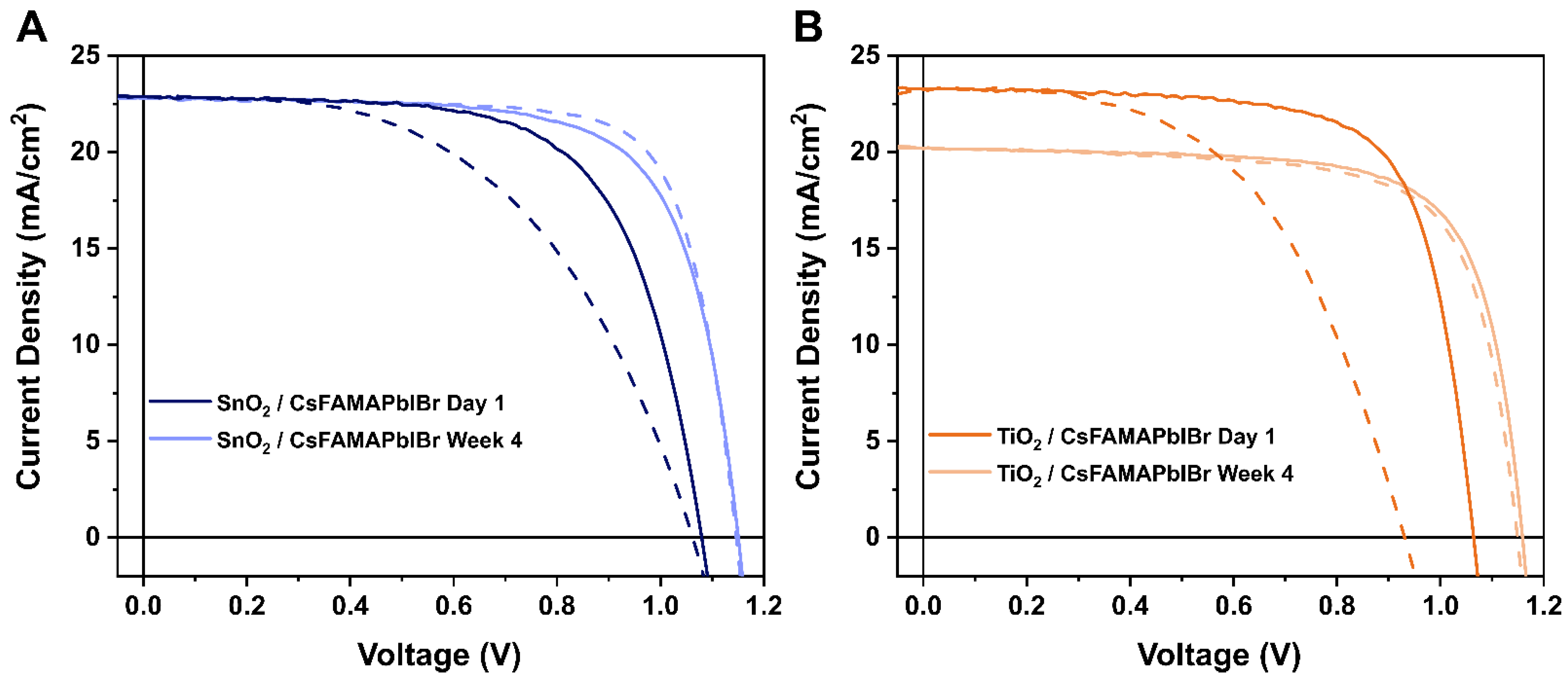
First, we studied the photovoltaic parameters of the solar cells with the different ESC (SnO2 and TiO2, n-type material), using the triple cation perovskite composition (CsFAMAPbIBr) and spiro-OMeTAD as HSC (p-type material). The photovoltaic parameters, obtained from the measurements of the current voltage (JV) curves are shown in Figure 1 and listed in Table 1. For clarity, we just show the results from day 1 (fresh) and day 28 (aged). Figure S1 summarises the photovoltaic parameters of the different measurement days. During the whole duration of the experiment, the devices were kept in dark and under dry air conditions (RH < 10% H2O), obtained via a synthetic airflow.
For fresh devices, the J-V hysteresis is more accentuated for devices with TiO2 as ESC. This might be attributed to the higher electron collection efficiency and better band alignment of energy levels of SnO2, which helps to decrease and even eliminate hysteresis [19]. However, in both cases, a reduction in the JV hysteresis is observed after keeping the solar cells in dark and dry air conditions (Figure 1 and Table 1). In previous publications, we and others have reported this kind of behaviour [18,19,20,21]. It has been suggested that O2 might have two major effects over this perovskite configuration. First, spiro-OMeTAD becomes oxidised, which helps to increase its conductivity, so getting a better charge extraction, and also to lower the HOMO value, which results in better band alignment, reducing carrier losses due to band mismatching [22]. The better charge extraction properties and reduced losses produce better values of FF and VOC in the aged solar cells. This process happens in the very early days after the storage of the devices, being clearly observable in the results on day 4 (Figure S1). Despite this increase in the very early days, these devices still present a high degree of hysteresis, and we have observed that the storage in dry air conditions over long periods of time helps to reduce it [17,18]. With longer aging times, device hysteresis reduces, obtaining higher values of VOC and FF. As well, the difference between the Voc values in the forward sweeps (from JSC to VOC) and reverse sweeps (from VOC to JSC) tends to be smaller (∆VOC = VOC (Rev) − VOC (fwd); ∆VOC(fresh, TiO2) = 134 mV versus ∆VOC(aged, TiO2) = 23 mV). We observe significant changes in VOC, increasing 85 mV for TiO2-based devices and 70 mV for SnO2-based devices. This important improvement might be associated with an improved carrier recombination at the interfaces, which greatly affects VOC. Metal halide perovskite are both ionic and electronic semiconductors, and the presence of mobile ions at the interfaces were appointed as the main cause for hysteresis in perovskite solar cells [13]. Thus, the reduction of hysteresis in our devices is related to a reduction in the influence of mobile ions over recombination. It has been previously suggested that the O2 molecules might also have a passivation effect on the perovskite lattice [23,24,25]. They might occupy some of the halide defects in the perovskite lattice, improving both ionic mobility and non-radiative carrier recombination. Using VOC stabilization, it is possible to track the influence of ionic mobility over carrier recombination, as this technique correlates a slow VOC stabilization with a slow ionic redistribution that leads to an increase interfacial recombination, and, thus, reduced VOC [26].
Another important feature is that SnO2-based devices do not show any change in the JSC, while we observed a reduction in TiO2-based devices. This is related to TiO2 causing photo-instability in the perovskite as it absorbs in the UV region [27,28], producing a slight degradation in the perovskite layer. Therefore, both from performance and from stability, we can confirm that SnO2 works better than TiO2 as ESC in n-i-p perovskite solar cells.
Then, we moved onto the study of the dependence of the ESC choice on the carrier recombination. For doing this, we employed a set of optoelectronic transient techniques, transient photovoltage (TPV) and transient photocurrent (TPC), which we have widely used in previous studies on perovskite solar cells, as well as on organic solar cells or dye sensitised solar cells [11,15,29]. Both techniques are small-perturbation techniques based on the application of a laser pulse that generates a small perturbation in voltage while using different background illumination intensities, which allow registering the experiment at different voltages. With TPV, we study the time that it takes for the voltage to return to its steady state, which depends on the background bias, and it is correlated with the recombination in the solar cell. TPC allows us to determine the number of charges that the laser pulse generates in the device. By combining both techniques, we can determine the charge density in the device with a technique termed as differential capacitance (DiffCap).
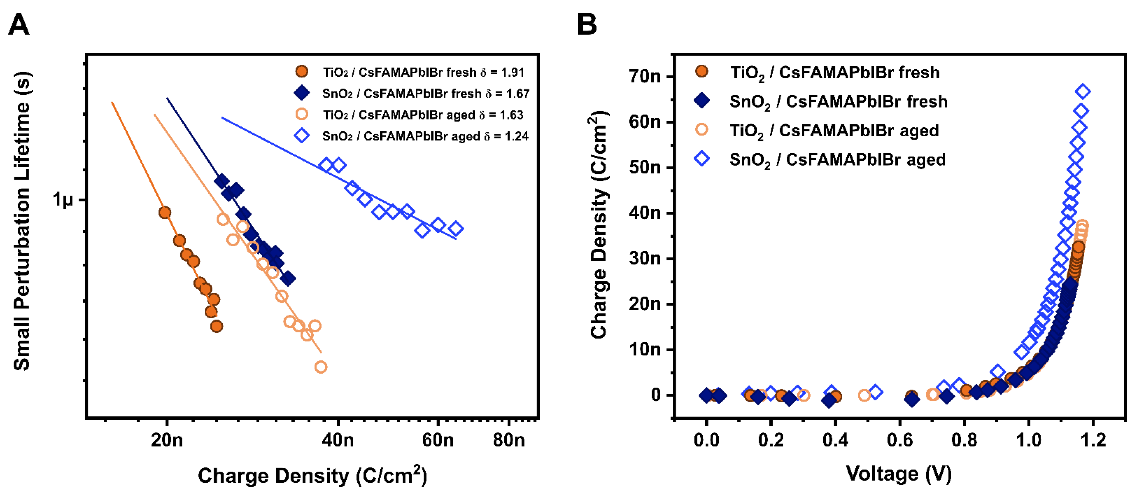
We study the recombination scenario with the small perturbation lifetimes obtained from the TPV decays at stable photovoltages. As it has been previously highlighted, at low-light intensities (low values of voltages), the lifetimes obtained from TPV are affected by the discharge of the ionic layer accumulated at the perovskite interfaces, which is the ionic redistribution once the device is illuminated [10,17]. Therefore, we should compare the lifetimes at high voltage values (Figure S2), which we can identify as the region in which carriers accumulate in the bulk of the perovskite (Figure S3). For this reason, we compare the recombination kinetics at different carrier densities (Figure 2A), obtained from the differential capacitance method (Figure 2B and Figure S3). In this way, we compare the kinetics when the contacts are depleted with charges, and they start to accumulate exponentially in the bulk [15]. This part is easily distinguishable in the analysis of the charge density as a function of voltage (Figure S3), where two different regimes are distinguished. First, a linear increase with voltage of the charge at lower values of voltage. Then, after the contacts are depleted with charges, they accumulate in the bulk of the perovskite, which we can observe as an exponential increase with voltage [15]. In these samples, as expected, we observe slower lifetimes for the aged devices (Figure 2A), which confirm that the increase in VOC is associated with a decrease in the recombination scheme of the system. This is also supported by the recombination orders in the perovskite. The small perturbation lifetime follows a power law dependence with the charge density , which is used to calculate the recombination order , ( [30]. All the devices are ruled by first and second order ( = 1–2) corresponding to the trap-assisted and surface recombination and band-to-band free carriers [31]. However, a clear decrease in the recombination order of the samples is observed after the aging treatment. Again, we associated it with a reduced carrier recombination at the interfaces because of the reduced ionic activity and motion. Using the recombination orders, it is possible to estimate the total carrier lifetime, or a pseudo-first-order lifetime of total excess charge carries via τ = τΔnδ (Figure S4). We observe very similar trends independently of the ESC employed.
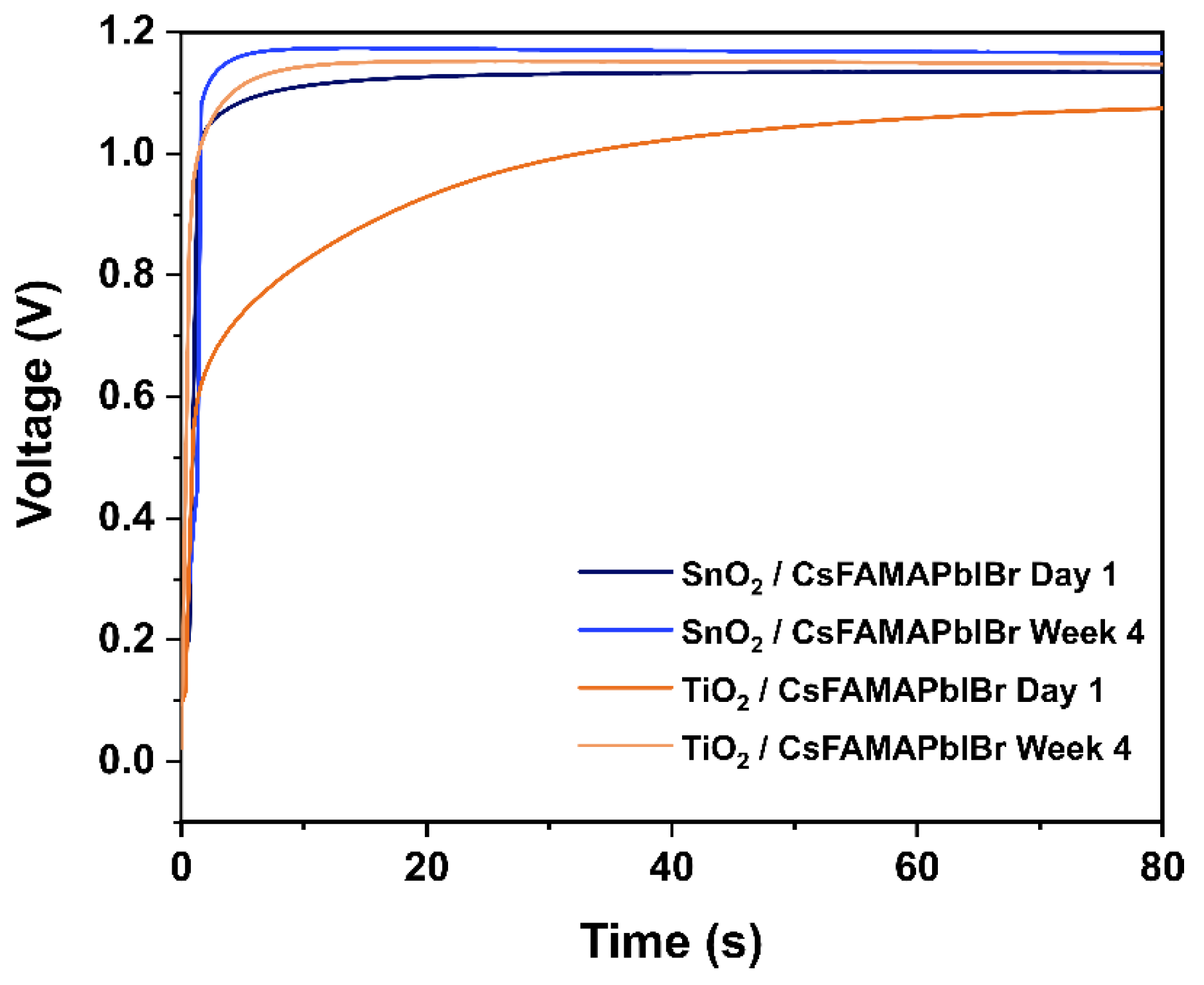
Next, we study the ionic influence over carrier recombination. For this purpose, we employed a variation of TPV, known as transient of the transient (TROTR), previously used by our research group and others [14,16,18]. In this technique, TPV transients are registered at the early stages of illumination, prior to VOC stabilization, where the ionic population is not fully distributed in the perovskite layer [17,18]. Figure 3 shows the VOC stability over time for fresh and aged devices. Here, we clearly observe a slower stabilization of voltage in illumination conditions for fresh devices mainly due to its higher hysteresis, which agrees well with results of previous studies [18].
This slow VOC stabilization is associated with the ionic redistribution in the perovskite layer, a slow process that affects carrier recombination, inducing slower VOC values until ions redistribute in the bulk of the perovskite [13,16]. During this time, when TPV transient pulses are registered—at 3, 5, 10 and 30 s—a negative spike appears. This negative transient, associated with an increased recombination at the interfaces is observable in every fresh device (see Figure 4A,C). Then, after the aging treatment (see Figure 4B,D), this spike is reduced for the case of TiO2, or it even disappears, as with SnO2-based devices and, as previously observed, after aging for 45 days [17]. These results suggest that the ionic accumulation at the interfaces enhances recombination, most likely, trap-assisted carrier recombination, thus yielding lower values of VOC. After storing the devices under dry air conditions, the ionic influence over carrier recombination is reduced, which suggests that O2 might have a passivation effect over carrier traps. However, since the hysteresis is not fully negligible for aged devices, they still present the negative transient signal attributed to the ionic movement. Moreover, there are differences between TiO2 and SnO2 aged that can be due to the better properties for SnO2 as ESC and the differences between mesoporous and planar structure, showing that planar structure avoids better the accumulation of carriers at the ESC/perovskite interface [32].
3.2. CsFAMAPIBr3 vs. MAPbI3-Based Devices on SnO2 Layer
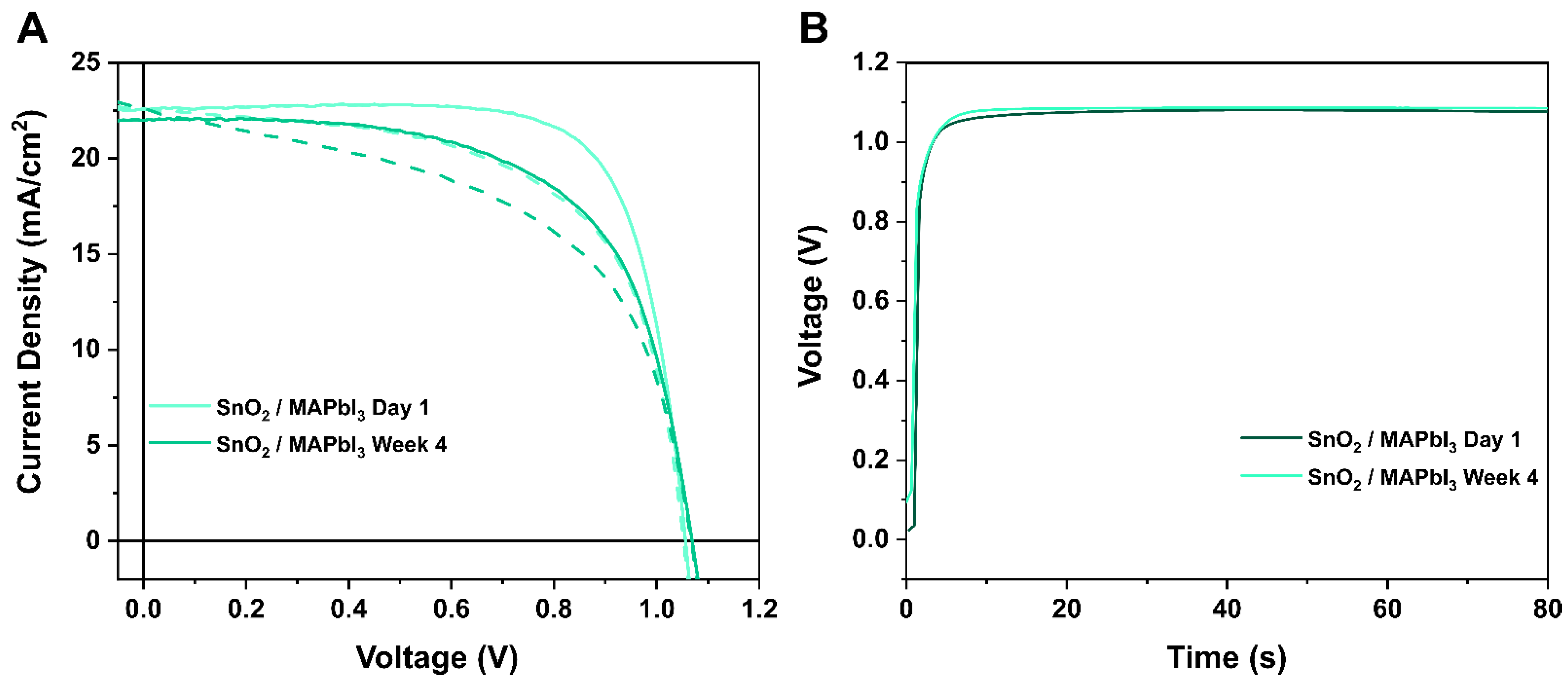
Finally, as we have already observed in previous studies, perovskite composition also plays an important role in the dynamics of ionic and charge recombination [18,21]. Therefore, we carried out the same studies on MAPbI3 fabricated on SnO2 and compared them with those of the triple cation perovskite shown in Section 3.1. JV curves show that hysteresis after aging SnO2/MAPbI3 for 28 days was not reduced as it occurs for SnO2/CsFAMAPbIBr devices, showing a less positive effect from the aging process (see Figure 5A and Figure S5, Table 2). There is an improvement in the fill factor occurring in the first days, but not in the VOC values, contrary to what we have observed for the triple cation perovskite composition. This reflects that carrier extraction might improve, probably due to the spiro-OMeTAD oxidation, with improvements in both conductivity and band alignment [17,33], but carrier recombination might increase, as we observe even smaller values of VOC over the period of the experiment. The effect of aging on MAPbI3 was also confirmed in the VOC stability over time shown in Figure 5B, where, for both fresh and aged devices, the time to reach the maximum VOC was almost the same (approximately 10 s). These observations on the photovoltaic parameters might suggest that not all the perovskite compositions are valid for this dry air aging treatment. In previous publications, we already observed that the use of bromine-based compositions instead of iodine were more prone to improve the photovoltaic parameters [34]. These results make us think that oxygen cannot passivate any defects at the MAPbI3 perovskite lattice, as we do not observe any long-term improvement in the photovoltaic performance.
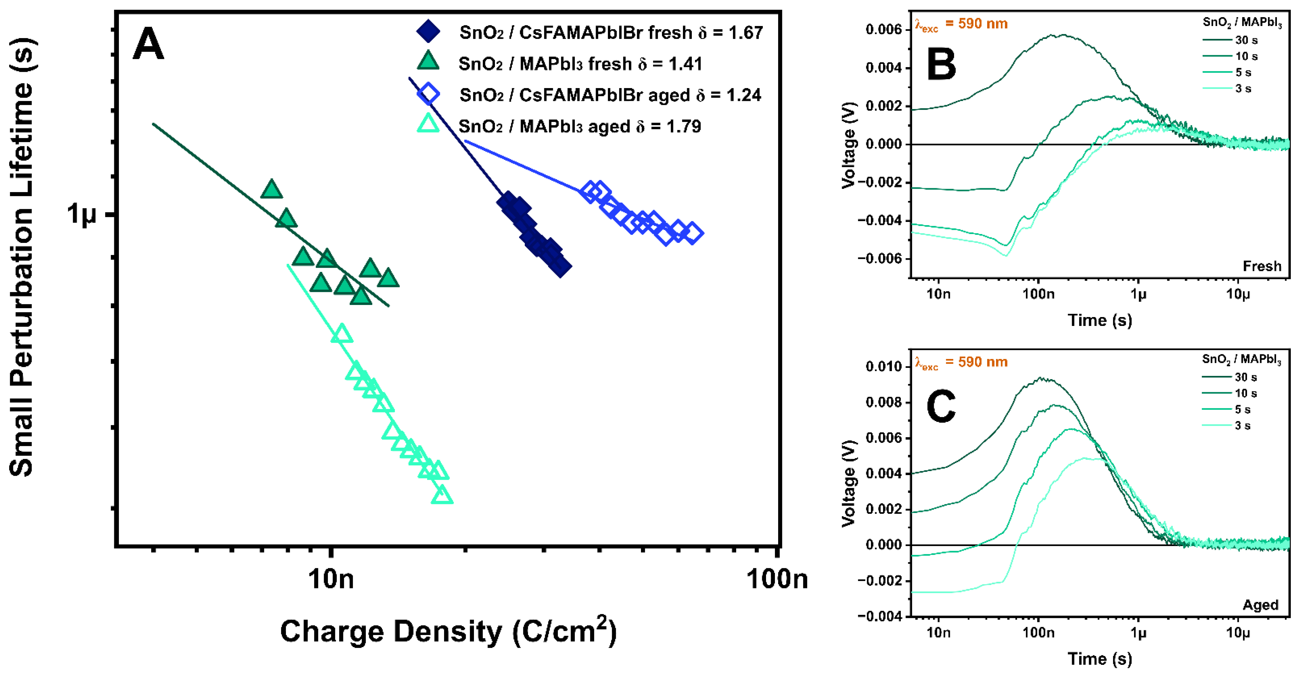
Then, we evaluate the carrier recombination kinetics for this composition using TPV and TPC. One thing that is clear is that with MAPbI3, there is a greater influence of the geometric capacitance on the differential capacitance technique, as it is shown in Figure S6, which might be attributed to an increased ionic accumulation at the interfaces [15,35]. This bigger influence can lead to a wrong interpretation of the carrier recombination scheme (Figure S7). Therefore, to perform a correct analysis of the different perovskite compositions, we remove the geometrical capacitance component (Figure 6A and Figure S7). After doing this, MAPbI3 presents a faster carrier recombination than CsFAMAPbIBr, which would explain the lower values of VOC after the aging treatment. Although the recombination orders for SnO2/MAPbI3 were in the same order as those for CsFAMAPbIBr devices (= 1–2), the recombination increased after 28 days instead of decreasing as for the other devices. Despite having discarded any benefits from oxygen exposure for MAPbI3 from the JV and VOC stability, we also measured TROTR (Figure 6B,C). Here, after 28 days of oxygen exposure, we observe a similar behaviour to TiO2-based CsFAMAPbIBr devices, as the negative component remains, but it is not as intense as in the fresh samples. While we ruled out the possibility of this being related to any changes in the bulk of the perovskite, it could be associated with the use of SnO2 as ESC. The higher conductivity and smaller surface area of SnO2 compared to the use of mesoporous TiO2 can have a positive effect on how ions move from this interface. However, as MAPbI3 JV curves did not improve, we continue observing the negative spike at very early timescales after the laser pulse. Ionic accumulation at the interfaces was described as the major influence for the great capacitance values reported for perovskites [9,35]. Moreover, recently, it was described that it is iodine defects the main responsible for such ionic accumulation. Additionally, these defects present a lower formation energy and higher defect density for MAPbI3 compared to the triple cation composition [36]. Therefore, the higher ionic density at the interfaces of MAPbI3 devices leads to higher capacitance values, increased carrier recombination, and finally, a higher degree of hysteresis in the devices. All the ionic components might contribute to the ionic capacitance observed. As well, it has been previously suggested that MA+ is the main responsible for the hysteresis observed in the JV curves. However, its ionic mobility is very slow compared to iodide and its vacancies, which may suggest that we cannot see any effect on the TROTR, but it is still observable in JV hysteresis [17,37,38].
4. Conclusions
In conclusion, CsFAMAPbIBr perovskite-based devices showed different performance when using either SnO2 or TiO2 as ESC. SnO2 as ESC showed higher electron collection efficiency and greater stability than TiO2. However, when comparing fresh and aged devices, both ESC reveal a decrease in recombination, being the aging process favourable for the VOC enhancement for all the CsFAMAPbIBr devices. These results suggest that, after storing the devices under dry conditions, O2 presents two main effects: the better extraction of charges because of the higher oxidation of spiro-OMeTAD, and the decrease in recombination due to its passivation effect over carrier traps. Interestingly, for the MAPbI3 perovskite devices, the aging process did not have the same results. The hysteresis was almost identical for fresh and aged devices and with higher recombination after the exposition of the devices. This clearly shows that perovskite composition plays an important role in the dynamics of ionic and charge recombination, with MAPbI3 having a greater ionic accumulation compared to CsFAMAPbIBr that leads to faster carrier recombination, and, consequently, worse device performances.
Supplementary Materials
The following supporting information can be downloaded at: https://www.mdpi.com/article/10.3390/app12094545/s1, Figure S1: Photovoltaic parameters of an average of 10 devices measured on fresh devices, and after 4 days, 1, 2, 4 (28 days), and 6 weeks for (A) SnO2/CsFAMAPbIBr, (B) TiO2/ CsFAMAPbIBr; Figure S2: Small perturbation lifetimes obtained from the exponential fitting of the TPV decays as a function of the light bias for the CsFAMAPbIBr samples deposited on top of TiO2 (orange circles) or SnO2 (blue diamonds) as ESC. The samples were measured fresh (filled symbols) and after the aging treatment (empty symbols); Figure S3: Capacitance obtained from the DiffCap method at different voltages (A) and after subtracting the geometric capacitance (charges accumulated at the contacts) (B). Charge density obtained at different voltages after the integration of the capacitance obtained with the DiffCap method, including carriers in the bulk and in the contacts (C). Charge density accumulated in the perovskite bulk (D). Small perturbation lifetime as a function of the total charge density accumulated in the device (charges in the bulk and in the contacts) (E). Small perturbation lifetime as a function of the charge density accumulated in the bulk of the perovskite. The lines represent the power law fitting used to calculate the recombination order (δ = λ + 1) of the devices (F); Figure S4: Total carrier lifetime () as a function of the charge density stored in the bulk of the perovskite; Figure S5: Photovoltaic parameters of an average of 10 devices measured on fresh devices, and after 4 days, 1, 2, 4 (28 days), and 6 weeks for SnO2/MAPbI3; Figure S6: Capacitance obtained from the DiffCap method at different voltages (A) and after subtracting the geometric capacitance (charges accumulated at the contacts) (B). Charge density obtained at different voltages after the integration of the capacitance obtained with the DiffCap method, including carriers in the bulk and in the contacts (C). Charge density accumulated in the perovskite bulk (D); Figure S7: Small perturbation lifetimes obtained from the exponential fitting of the TPV decays as a function of the light bias (A) for the CsFAMAPbIBr (blue) and MAPbI3 (green) samples desposited on top of SnO2 as ESC. The samples were measured fresh (filled symbols) and after the aging treatment (empty symbols). Small perturbation lifetime as a function of the total charge density accumulated in the device (charges in the bulk and in the contacts) (B). Small perturbation lifetime as a function of the charge density accumulated in the bulk of the perovskite. The lines represent the power law fitting used to calculate the recombination order (δ = λ + 1) of the devices (C). Total carrier lifetime () as a function of the charge density stored in the bulk of the perovskite (D).
Author Contributions
Conceptualization, J.J.-L. and E.P.; methodology J.J.-L. and E.P.; validation J.J.-L., M.M. and E.P.; writing—original draft, review and editing J.J.-L., M.M. and E.P.; supervision E.P. All authors have read and agreed to the published version of the manuscript.
Funding
This research was funded by MINECO (project PID2019-109389RB-I00) and SGRAGAUR2017SGR00978.
Institutional Review Board Statement
Not applicable.
Informed Consent Statement
Not applicable.
Data Availability Statement
Not applicable.
Acknowledgments
The authors acknowledge funding from MINECO and the financial support from ICIQ, CERCA, and ICREA.
Conflicts of Interest
The authors declare no conflict of interest.
References
- Valadi, K.; Gharibi, S.; Taheri-Ledari, R.; Akin, S.; Maleki, A.; Shalan, A.E. Metal oxide electron transport materials for perovskite solar cells: A review. Environ. Chem. Lett. 2021, 19, 2185–2207. [Google Scholar] [CrossRef]
- Cao, Z.; Li, C.; Deng, X.; Wang, S.; Yuan, Y.; Chen, Y.; Wang, Z.; Liu, Y.; Ding, L.; Hao, F. Metal oxide alternatives for efficient electron transport in perovskite solar cells: Beyond TiO2 and SnO2. J. Mater. Chem. A 2020, 8, 19768–19787. [Google Scholar] [CrossRef]
- Abuhelaiqa, M.; Shibayama, N.; Gao, X.-X.; Kanda, H.; Nazeeruddin, M.K. SnO2/TiO2 Electron Transporting Bilayers: A Route to Light Stable Perovskite Solar Cells. ACS Appl. Energy Mater. 2021, 4, 3424–3430. [Google Scholar] [CrossRef]
- Anaraki, E.H.; Kermanpur, A.; Steier, L.; Domanski, K.; Matsui, T.; Tress, W.; Saliba, M.; Abate, A.; Grätzel, M.; Hagfeldt, A.; et al. Highly efficient and stable planar perovskite solar cells by solution-processed tin oxide. Energy Environ. Sci. 2016, 9, 3128–3134. [Google Scholar] [CrossRef]
- Eliwi, A.A.; Byranvand, M.M.; Fassl, P.; Khan, M.R.; Hossain, I.M.; Frericks, M.; Ternes, S.; Abzieher, T.; Schwenzer, J.A.; Mayer, T.; et al. Optimization of SnO2 electron transport layer for efficient planar perovskite solar cells with very low hysteresis. Mater. Adv. 2021, 3, 456–466. [Google Scholar] [CrossRef]
- Wolff, C.M.; Caprioglio, P.; Stolterfoht, M.; Neher, D. Nonradiative Recombination in Perovskite Solar Cells: The Role of Interfaces. Adv. Mater. 2019, 31, e1902762. [Google Scholar] [CrossRef] [Green Version]
- Wu, N.; Wu, Y.; Walter, D.; Shen, H.; Duong, T.; Grant, D.; Barugkin, C.; Fu, X.; Peng, J.; White, T.; et al. Identifying the Cause of Voltage and Fill Factor Losses in Perovskite Solar Cells by Using Luminescence Measurements. Energy Technol. 2017, 5, 1827–1835. [Google Scholar] [CrossRef] [Green Version]
- Montcada, N.F.; Méndez, M.; Cho, K.T.; Nazeeruddin, M.K.; Palomares, E. Photo-induced dynamic processes in perovskite solar cells: The influence of perovskite composition in the charge extraction and the carrier recombination. Nanoscale 2018, 10, 6155–6158. [Google Scholar] [CrossRef]
- Shao, S.; Loi, M.A. The Role of the Interfaces in Perovskite Solar Cells. Adv. Mater. Interfaces 2019, 7, 1901469. [Google Scholar] [CrossRef] [Green Version]
- Jiménez-López, J.; Cambarau, W.; Cabau, L.; Palomares, E. Charge Injection, Carriers Recombination and HOMO Energy Level Relationship in Perovskite Solar Cells. Sci. Rep. 2017, 7, 6101. [Google Scholar] [CrossRef]
- Xu, L.; Aumaitre, C.; Kervella, Y.; Lapertot, G.; Rodríguez-Seco, C.; Palomares, E.; Demadrille, R.; Reiss, P. Increasing the Efficiency of Organic Dye-Sensitized Solar Cells over 10.3% Using Locally Ordered Inverse Opal Nanostructures in the Photoelectrode. Adv. Funct. Mater. 2018, 28, 1706291. [Google Scholar] [CrossRef]
- Ryan, J.W.; Marin-Beloqui, J.M.; Albero, J.; Palomares, E. Nongeminate Recombination Dynamics–Device Voltage Relationship in Hybrid PbS Quantum Dot/C60 Solar Cells. J. Phys. Chem. C 2013, 117, 17470–17476. [Google Scholar] [CrossRef]
- Calado, P.; Telford, A.M.; Bryant, D.; Li, X.; Nelson, J.; O’Regan, B.C.; Barnes, P.R.F. Evidence for ion migration in hybrid perovskite solar cells with minimal hysteresis. Nat. Commun. 2016, 7, 13831. [Google Scholar] [CrossRef] [PubMed]
- Pockett, A.; Carnie, M.J. Ionic Influences on Recombination in Perovskite Solar Cells. ACS Energy Lett. 2017, 2, 1683–1689. [Google Scholar] [CrossRef] [Green Version]
- Palomares, E.; Montcada, N.F.; Méndez, M.; Jiménez-López, J.; Yang, W.; Boschloo, G. Photovoltage/photocurrent transient techniques. In Characterization Techniques for Perovskite Solar Cell Materials; Pazoki, M., Hagfeldt, A., Edvinsson, T., Eds.; Elsevier: Amsterdam, The Netherlands, 2020; pp. 161–180. ISBN 978-0-12-814727-6. [Google Scholar]
- Calado, P.; Burkitt, D.; Yao, J.; Troughton, J.; Watson, T.M.; Carnie, M.J.; Telford, A.M.; O’Regan, B.C.; Nelson, J.; Barnes, P.R. Identifying Dominant Recombination Mechanisms in Perovskite Solar Cells by Measuring the Transient Ideality Factor. Phys. Rev. Appl. 2019, 11, 44005. [Google Scholar] [CrossRef] [Green Version]
- Jiménez-López, J.; Palomares, E. Interfacial recombination kinetics in aged perovskite solar cells measured using transient photovoltage techniques. Nanoscale 2019, 11, 20024–20029. [Google Scholar] [CrossRef]
- Sun, L.; Méndez, M.; Jiménez-López, J.; Zhu, M.; Xiao, Y.; Gil, E.J.P. Analysis of the Oxygen Passivation Effects on MAPbI3 and MAPbBr3 in Fresh and Aged Solar Cells by the Transient Photovoltage Technique. ChemPlusChem 2021, 86, 1316–1321. [Google Scholar] [CrossRef]
- Wang, C.; Xiao, C.; Yu, Y.; Zhao, D.; Awni, R.A.; Grice, C.R.; Ghimire, K.; Constantinou, I.; Liao, W.; Cimaroli, A.J.; et al. Understanding and Eliminating Hysteresis for Highly Efficient Planar Perovskite Solar Cells. Adv. Energy Mater. 2017, 7, 1700414. [Google Scholar] [CrossRef]
- Fei, C.; Wang, H. Age-induced recrystallization in perovskite solar cells. Org. Electron. 2019, 68, 143–150. [Google Scholar] [CrossRef]
- Su, L.; Màlaga, M.M.; Zhu, M.; Xiao, Y.; Gil, E.P. Use of organic bulk-heterojunction solar cells as selective contacts in wide band-gap perovskite solar cells: Advantages and limitations. J. Mater. Chem. A 2021, 9, 13979–13985. [Google Scholar] [CrossRef]
- Cho, Y.; Kim, H.D.; Zheng, J.; Bing, J.; Li, Y.; Zhang, M.; Green, M.A.; Wakamiya, A.; Huang, S.; Ohkita, H.; et al. Elucidating Mechanisms behind Ambient Storage-Induced Efficiency Improvements in Perovskite Solar Cells. ACS Energy Lett. 2021, 6, 925–933. [Google Scholar] [CrossRef]
- Liu, S.-C.; Li, Z.; Yang, Y.; Wang, X.; Chen, Y.-X.; Xue, D.-J.; Hu, J.-S. Investigation of Oxygen Passivation for High-Performance All-Inorganic Perovskite Solar Cells. J. Am. Chem. Soc. 2019, 141, 18075–18082. [Google Scholar] [CrossRef] [PubMed]
- Senocrate, A.; Acartürk, T.; Kim, G.Y.; Merkle, R.; Starke, U.; Grätzel, M.; Maier, J. Interaction of oxygen with halide perovskites. J. Mater. Chem. A 2018, 6, 10847–10855. [Google Scholar] [CrossRef] [Green Version]
- Meggiolaro, D.; Mosconi, E.; De Angelis, F. Mechanism of Reversible Trap Passivation by Molecular Oxygen in Lead-Halide Perovskites. ACS Energy Lett. 2017, 2, 2794–2798. [Google Scholar] [CrossRef]
- Wang, H.; Guerrero, A.; Bou, A.; Al-Mayouf, A.M.; Bisquert, J. Kinetic and material properties of interfaces governing slow response and long timescale phenomena in perovskite solar cells. Energy Environ. Sci. 2019, 12, 2054–2079. [Google Scholar] [CrossRef]
- Roose, B.; Baena, J.-P.C.; Gödel, K.C.; Graetzel, M.; Hagfeldt, A.; Steiner, U.; Abate, A. Mesoporous SnO2 electron selective contact enables UV-stable perovskite solar cells. Nano Energy 2016, 30, 517–522. [Google Scholar] [CrossRef] [Green Version]
- Xiong, L.; Guo, Y.; Wen, J.; Liu, H.; Yang, G.; Qin, P.; Fang, G. Review on the Application of SnO2 in Perovskite Solar Cells. Adv. Funct. Mater. 2018, 28, 1802757. [Google Scholar] [CrossRef]
- Torimtubun, A.A.A.; Méndez, M.; Sánchez, J.G.; Pallares, J.; Palomares, E.J.; Marsal, L.F. Shelf Lifetime Analysis of Organic Solar Cells Combining Frequency and Time Resolved Techniques. Sustain. Energy Fuels 2021, 5, 6498–6508. [Google Scholar] [CrossRef]
- Shuttle, C.G.; Regan, B.O.; Ballantyne, A.M.; Nelson, J.; Bradley, D.; De Mello, J.; Durrant, J.R. Experimental determination of the rate law for charge carrier decay in a polythiophene: Fullerene solar cell. Appl. Phys. Lett. 2008, 92, 93311. [Google Scholar] [CrossRef]
- Wolff, C.M.; Bourelle, S.A.; Phuong, L.Q.; Kurpiers, J.; Feldmann, S.; Caprioglio, P.; Marquez, J.A.; Wolansky, J.; Unold, T.; Stolterfoht, M.; et al. Orders of Recombination in Complete Perovskite Solar Cells–Linking Time-Resolved and Steady-State Measurements. Adv. Energy Mater. 2021, 11, 2101823. [Google Scholar] [CrossRef]
- Tseng, C.-C.; Chen, L.-C.; Chang, L.-B.; Wu, G.-M.; Feng, W.-S.; Jeng, M.-J.; Chen, D.W.; Lee, K.-L. Cu2O-HTM/SiO2-ETM assisted for synthesis engineering improving efficiency and stability with heterojunction planar perovskite thin-film solar cells. Sol. Energy 2020, 204, 270–279. [Google Scholar] [CrossRef]
- Kasparavicius, E.; Franckevičius, M.; Malinauskiene, V.; Genevičius, K.; Getautis, V.; Malinauskas, T. Oxidized Spiro-OMeTAD: Investigation of Stability in Contact with Various Perovskite Compositions. ACS Appl. Energy Mater. 2021, 4, 13696–13705. [Google Scholar] [CrossRef] [PubMed]
- McGovern, L.; Futscher, M.H.; Muscarella, L.A.; Ehrler, B. Understanding the Stability of MAPbBr3 versus MAPbI3: Suppression of Methylammonium Migration and Reduction of Halide Migration. J. Phys. Chem. Lett. 2020, 11, 7127–7132. [Google Scholar] [CrossRef] [PubMed]
- Ebadi, F.; Taghavinia, N.; Mohammadpour, R.; Hagfeldt, A.; Tress, W. Origin of apparent light-enhanced and negative capacitance in perovskite solar cells. Nat. Commun. 2019, 10, 1574. [Google Scholar] [CrossRef] [Green Version]
- Tammireddy, S.; Reichert, S.; An, Q.; Taylor, A.D.; Ji, R.; Paulus, F.; Vaynzof, Y.; Deibel, C. Temperature-Dependent Ionic Conductivity and Properties of Iodine-Related Defects in Metal Halide Perovskites. ACS Energy Lett. 2021, 7, 310–319. [Google Scholar] [CrossRef]
- Zai, H.; Ma, Y.; Chen, Q.; Zhou, H. Ion migration in halide perovskite solar cells: Mechanism, characterization, impact and suppression. J. Energy Chem. 2021, 63, 528–549. [Google Scholar] [CrossRef]
- Futscher, M.H.; Lee, J.M.; McGovern, L.; Muscarella, L.A.; Wang, T.; Haider, M.I.; Fakharuddin, A.; Schmidt-Mende, L.; Ehrler, B. Quantification of ion migration in CH3NH3PbI3 perovskite solar cells by transient capacitance measurements. Mater. Horizons 2019, 6, 1497–1503. [Google Scholar] [CrossRef] [Green Version]
Figure 1.
JV curves measured at 1 Sun conditions (100 mW/cm2, AM 1.5 G) in forward (dashed line) and reverse (solid line) scan for CsFAMAPbIBr on SnO2 (A) and TiO2 (B) in fresh and aged devices.
Figure 1.
JV curves measured at 1 Sun conditions (100 mW/cm2, AM 1.5 G) in forward (dashed line) and reverse (solid line) scan for CsFAMAPbIBr on SnO2 (A) and TiO2 (B) in fresh and aged devices.

Figure 2.
(A) Carrier lifetime obtained from TPV decays as a function of the carrier density after the subtraction of the geometric capacitance. (B) Carrier density obtained from the integration of the capacitance and after the subtraction of the geometric capacitance. The orange circles represent the TiO2/CsFAMAPbIBr, and blue diamonds represent the SnO2/CsFAMAPbIBr. In both cases, the filled symbols represent the fresh samples and the empty symbols—the samples after the aging treatment.

Figure 3.
VOC stability over time for CsFAMAPbIBr on TiO2 and SnO2 for fresh and aged devices.

Figure 4.
TPV transients in logarithm scale obtained at different illumination times at 1 Sun intensity for fresh and aged CsFAMAPbIBr on TiO2 (A,B) and SnO2 (C,D) ESC.
Figure 4.
TPV transients in logarithm scale obtained at different illumination times at 1 Sun intensity for fresh and aged CsFAMAPbIBr on TiO2 (A,B) and SnO2 (C,D) ESC.

Figure 5.
JV curves measured at 1 Sun conditions (100 mW/cm2, AM 1.5G) in forward (dashed line) and reverse (solid line) scan for fresh and aged samples of MAPbI3 deposited on SnO2 (A) and VOC stability over a period of time for fresh and aged MAPbI3 samples (B).
Figure 5.
JV curves measured at 1 Sun conditions (100 mW/cm2, AM 1.5G) in forward (dashed line) and reverse (solid line) scan for fresh and aged samples of MAPbI3 deposited on SnO2 (A) and VOC stability over a period of time for fresh and aged MAPbI3 samples (B).

Figure 6.
Carrier lifetime obtained from TPV decays as a function of the carrier density after the subtraction of the geometric capacitance for SnO2/CsFAMAPbIBr and SnO2/MAPbI3 samples (A). TPV decays obtained during different times of illumination for fresh (B) and aged (C) SnO2/MAPbI3.
Figure 6.
Carrier lifetime obtained from TPV decays as a function of the carrier density after the subtraction of the geometric capacitance for SnO2/CsFAMAPbIBr and SnO2/MAPbI3 samples (A). TPV decays obtained during different times of illumination for fresh (B) and aged (C) SnO2/MAPbI3.


Table 1.
Summary of the photovoltaic parameters for CsFAMAPbIBr on either TiO2 or SnO2 layers measured in fresh (1 day) and aged (28 days) conditions.
Table 1.
Summary of the photovoltaic parameters for CsFAMAPbIBr on either TiO2 or SnO2 layers measured in fresh (1 day) and aged (28 days) conditions.
| ESC/Perovskite | Aging Days | Sweep | JSC [mA/cm2] | VOC [V] | FF | PCE [%] (Champion Cell) |
|---|---|---|---|---|---|---|
| TiO2/CsFAMAPbIBr | 1 | Forw | 21.7 ± 1.1 | 0.930 ± 0.011 | 0.53 ± 0.01 | 10.7 ± 0.4 (11.5) |
| Rev | 22.1 ± 1.1 | 1.054 ± 0.029 | 0.71 ± 0.01 | 16.6 ± 0.9 (18.4) | ||
| 28 | Forw | 20.5 ± 1.1 | 1.116 ± 0.018 | 0.67 ± 0.05 | 15.3 ± 1.7 (16.8) | |
| Rev | 20.5 ± 0.3 | 1.139 ± 0.011 | 0.70 ± 0.02 | 16.3 ± 0.6 (17.0) | ||
| SnO2/CsFAMAPbIBr | 1 | Forw | 22.0 ± 0.9 | 1.062 ± 0.013 | 0.50 ± 0.02 | 11.8 ± 0.5 (12.5) |
| Rev | 21.8 ± 0.9 | 1.081 ± 0.022 | 0.66 ± 0.01 | 15.6 ± 1.0 (17.9) | ||
| 28 | Forw | 21.6 ± 0.9 | 1.146 ± 0.006 | 0.71 ± 0.04 | 17.5 ± 1.0 (19.6) | |
| Rev | 21.8 ± 0.7 | 1.151 ± 0.005 | 0.70 ± 0.02 | 17.5 ± 0.6 (18.6) |
Table 2.
Summary of the photovoltaic parameters for MAPbI3 on SnO2 measured in fresh (1 day) and aged (28 days) conditions.
Table 2.
Summary of the photovoltaic parameters for MAPbI3 on SnO2 measured in fresh (1 day) and aged (28 days) conditions.
| ESC/Perovskite | Aging Days | Sweep | JSC [mA/cm2] | VOC [V] | FF | PCE [%] (Champion Cell) |
|---|---|---|---|---|---|---|
| SnO2/MAPbI3 | Day 1 | Fwd | 21.2 ± 0.8 | 1.072 ± 0.007 | 0.56 ± 0.02 | 12.7 ± 0.6 (13.6) |
| Rev | 20.5 ± 0.9 | 1.076 ± 0.006 | 0.64 ± 0.01 | 14.2 ± 0.6 (15.0) | ||
| Week 4 | Fwd | 21.2 ± 0.9 | 1.058 ± 0.013 | 0.64 ± 0.02 | 14.2 ± 0.8 (15.5) | |
| Rev | 21.0 ± 0.9 | 1.065 ± 0.007 | 0.71 ± 0.02 | 16.0 ± 1.1 (17.7) |
Publisher’s Note: MDPI stays neutral with regard to jurisdictional claims in published maps and institutional affiliations. |
© 2022 by the authors. Licensee MDPI, Basel, Switzerland. This article is an open access article distributed under the terms and conditions of the Creative Commons Attribution (CC BY) license (https://creativecommons.org/licenses/by/4.0/).
Share and Cite
MDPI and ACS Style
Jiménez-López, J.; Méndez, M.; Palomares, E. Influence of the Electron Selective Contact on the Interfacial Recombination in Fresh and Aged Perovskite Solar Cells. Appl. Sci. 2022, 12, 4545. https://doi.org/10.3390/app12094545
AMA Style
Jiménez-López J, Méndez M, Palomares E. Influence of the Electron Selective Contact on the Interfacial Recombination in Fresh and Aged Perovskite Solar Cells. Applied Sciences. 2022; 12(9):4545. https://doi.org/10.3390/app12094545
Chicago/Turabian StyleJiménez-López, Jesús, Maria Méndez, and Emilio Palomares. 2022. "Influence of the Electron Selective Contact on the Interfacial Recombination in Fresh and Aged Perovskite Solar Cells" Applied Sciences 12, no. 9: 4545. https://doi.org/10.3390/app12094545
Note that from the first issue of 2016, this journal uses article numbers instead of page numbers. See further details here.