

Preliminary Biomechanical Evaluation of a Novel Exoskeleton Robotic System to Assist Stair Climbing
by
 , ,
, ,
Max Böhme
1,* ,
,
Hans-Peter Köhler
2,
Robert Thiel
1,
Jens Jäkel
1,
Johannes Zentner
1 and
Maren Witt
2 1
Faculty of Engineering, Leipzig University of Applied Sciences, Karl-Liebknecht-Str. 132, 04277 Leipzig, Germany
2
Department of Biomechanics in Sports, Faculty of Sport Science, University Leipzig, Jahnallee 59, 04109 Leipzig, Germany
*
Author to whom correspondence should be addressed.
Appl. Sci. 2022, 12(17), 8835; https://doi.org/10.3390/app12178835
Submission received: 17 August 2022
/
Revised: 30 August 2022
/
Accepted: 31 August 2022
/
Published: 2 September 2022
(This article belongs to the Special Issue Exoskeleton Robotic Systems)
Abstract
:A novel exoskeleton robotic system was developed to assist stair climbing. This active demonstrator consists of a motor with a cable system, various sensors, and a control system with a power supply. The objective of this preliminary study is a biomechanical evaluation of the novel system to determine its effectiveness in use. For this purpose, three test persons were biomechanically investigated, who performed stair ascents and descents with and without the exoskeleton. Kinematics, kinetics, and muscle activity of the knee extensors were measured. The measured data were biomechanically simulated in order to evaluate the characteristics of joint angles, moments, and reaction forces. The results show that the new exoskeleton assists both the ascent and the descent according to the measured surface electromyography (sEMG) signals, as the knee extensors are relieved by an average of 19.3%. In addition, differences in the interaction between the test persons and the system were found. This could be due to a slightly different operation of the assisting force or to the different influence of the system on the kinematics of the users.
1. Introduction
An exoskeleton is a wearable device with rigid and/or soft components, that augments, assists, enables, and/or enhances physical activity through mechanical interaction with the body [1]. Furthermore, an exoskeleton robotic system is an exoskeleton with all of the associated components such as a power supply, equipment, software, and communications that are necessary to make it fully functional. In recent years, more and more exoskeletons have been developed and tested for a wide range of applications [2]. Thus, a number of systems were also developed to assist people, especially elderly people, exclusively during stair climbing [3,4]. For example, an active system has been developed by [5] that consists of five parts and weighs about 13.5 kg. In this system, additional torque is applied to the knee and ankle joints of both legs by tension elements, which are actuated by two DC motors that are located on the back with a power of 140 W each [5]. Another example is a lower limb exoskeleton that is described in [6]. This carbon fibre bilateral system assists the extension and flexion moment of the knee joint by two pneumatic actuators each. The actuators are controlled by five non-invasive surface electromyographs (sEMG) that have to be placed on the user’s thigh muscles in advance [6].
All systems of the state of the art devices for the exclusive assistance of elderly people during stair climbing have different actuator configurations. However, biomechanical studies to evaluate the need for assistance have shown that only knee extension should be assisted during ascent and descent [3]. In this way, the natural muscle weakness that occurs with age can be compensated [7]. The current systems do not meet this requirement and assist or actuate more than is actually needed.
Furthermore, the effectiveness of these exoskeletons has not been evaluated or has only been evaluated in very simple biomechanical studies. For example, trials were conducted with the active system by [5] and it was described that the system helps the user to climb stairs. However, this statement is only based on the experience and sense of the user and has not been evaluated by measurements. The lower limb exoskeleton was tested with only one subject, but for a period of 10 days [6]. From the recordings of knee angle, sEMG of knee extensors and flexors, and metabolic costs, a reduction in both flexor muscles activity by up to 61% could be concluded [6]. Also, only one subject (age 37 years, height 1.70 m, weight 69 kg) was examined in the preliminary walking experiments for the test of the robotic hip exoskeleton [8]. Although the test was carried out on a standardized staircase (step height 0.18 m, tread 0.30 m) according to [9], the aim of the test was not the biomechanical evaluation of the exoskeleton. A more comprehensive investigation was carried out on the Hiteexosuit with three test persons [10]. Here, the tensile force of the actuator and the knee joint angular displacements were measured during stair climbing [10]. The lower extremity exoskeleton achieved a knee joint moment of 0.8 Nm/kg in stair climbing experiments, which were not further described [11]. It was concluded that the design and hybrid control strategy are functional and improve mobility during stair climbing. Furthermore, trials were conducted with Beihang University’s lower limb exo on various indoor and outdoor staircases [12]. However, only the kinematics were measured to evaluate a gait algorithm, but not to investigate the biomechanical effectiveness of the system itself [12]. The passive exoskeleton PKAExo was only mechanically verified in one experiment [13,14]. Nevertheless, the authors noted that this experiment does not sufficiently prove that the passive system neither reduces muscle activity during weight-bearing ascending locomotion, nor that it improves human metabolic productivity [14]. They already mentioned that sEMG signals, metabolic costs, and also external forces should be measured in order to evaluate the system [14]. This was done, for example, for an evaluation of an exoskeleton to assist sit-to-stand movements [15].
In recent and more extensive studies on the effectiveness of exoskeletons, kinematics, external forces, sEMG signals, and metabolic costs are measured in several subjects during exercises with and without the exoskeleton [16,17]. In addition, biomechanical simulations are increasingly used for the evaluation of results [17]. The advantage is that internal forces that cannot be measured directly, such as joint reaction forces, can be determined and analyzed for an evaluation of the system.
Considering the state of the art devices, there are no studies which quantify the complex kinetics and kinematics during stair climbing with an exoskeleton. Therefore, the objective of this study is to present and biomechanically evaluate the novel robotic exoskeleton for stair climbing. In detail, the change of kinematics in the sagittal and frontal plane during ascent and descent due to the influence of the exoskeleton will be investigated. Furthermore, it will be examined whether the required joint moments of the user can be reduced by the active system, thus providing assistance. This is also to be evaluated by the muscle activities of the knee extensors with and without the use of the exoskeleton. Finally, a potential change in the internal knee joint reaction forces should be evaluated.
2. Materials and Methods
2.1. Exoskeleton
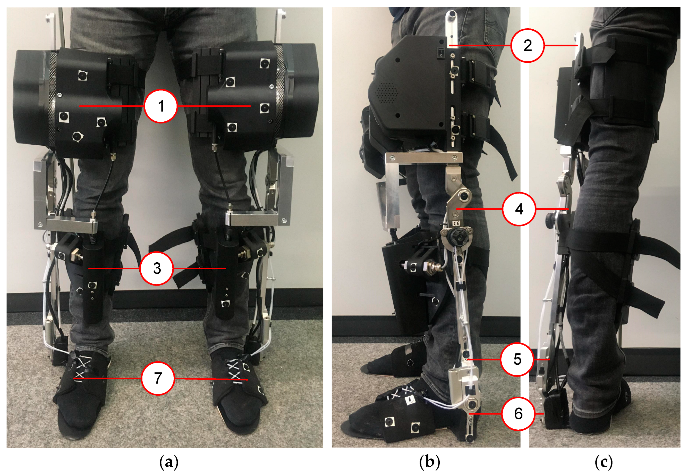
The novel exoskeleton robotic system to assist stair climbing, shown in Figure 1, is according to ISO 13482 a restraint type physical assistant robot, since the system is fastened to the human during use. The intended purpose of the exoskeletal movement assisting system (eBUS; German abbreviation for exoskelettales Bewegungsunterstützungssystem) is to assist people with a natural lack of strength, such as elderly people. In previous biomechanical studies, it was found that an exoskeleton for elderly people should assist them in knee extension during ascent and descent as well [3]. Therefore, the active exoskeleton eBUS was designed that assists only the knee joint actively in extension in order to maintain minimal actuation. Furthermore, the eBUS is characterized by a unilateral and rigid structure and is symmetrically designed for the left and right leg. The system works independently for each leg and weighs 6.1 kg per leg. The components that are attached to the thigh have a total mass of 4.4 kg (72%), those on the shank 1.5 kg (24%), and on the foot 0.2 kg (4%). Thus, it was possible to consider the fact that the low mass at the distal segment (foot) is advantageous for the acceleration of the foot.
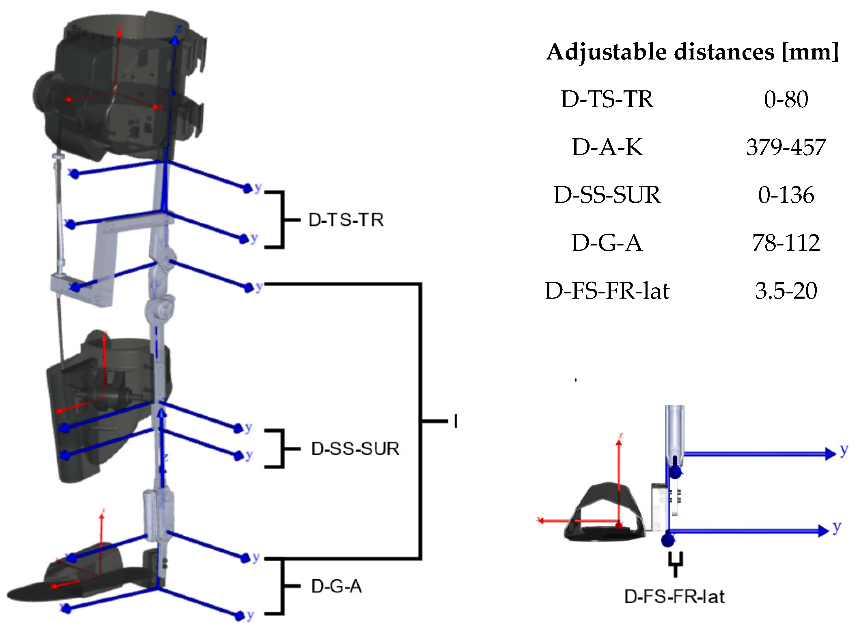
The eBUS consists of seven parts per leg with two rotational joints corresponding to flexion/extension of the knee and dorsiflexion/plantarflexion of the ankle (Figure 1). Three of the seven segments are attached to the user’s thigh, shank, and foot and represent the interface. These three segments are connected to each other through four sliding rails. The four rails create the two rotational joints with one degree of freedom, that should ideally be coaxial with the human knee and ankle joints, respectively. The sliding rails enable the eBUS to be adjustable for different anthropometries of users, as shown in Figure 2.
The foot segment of the exoskeleton surrounds the human foot and consists of a compliant material to allow the foot to roll off. This design is intended to take into account the second DOF in the ankle joint so that lateral movements in the frontal plane are possible to increase the user comfort. All the three interface attachment components are adjustable to consider individual anthropometry to increase comfort.
The active force to assist stair climbing is implemented through a Bowden cable, which is tensioned between the thigh segment and the shank segment of the eBUS and spans the human knee anteriorly. The drive system from a Maxon motor ag (Sachseln, Switzerland) consists of a brushless DC motor (EC 60 flat, 150 W) with integrated encoder (Encoder MILE 4096 steps per turn, two channels with Line Driver) and a gearhead (GP 52 C) that is fixed to the exoskeleton thigh. The energy storage unit is also attached to the thigh segment and consists of seven lithium-ion cells (Samsung INR18650-29E) of type 7S1P (FRIWO Gerätebau GmbH, Ostbevern, Germany). The driver system pulls the cable and creates a pulling force. The motor is controlled by a servo controller (ESCON Module 50/5, Maxon motor ag, Sachseln, Switzerland) in combination with an Arduino® Mega 2560 (Arduino SA, Lugano, Switzerland). The force in the bowden cable is measured at any time by a ZAD 500-T tension force sensor (HAEHNE Elektronische Messgeräte GmbH, Erkrath, Germany). The force vector direction is independent of the knee angle as the cable has a fixed distance with 0.1 m from the patella of the knee. The pulling force results in an external moment through the rigid structure of the exoskeleton to assist knee extension. This external force is active only if the corresponding leg is in the stance phase of the movement, which is detected by four pressure sensors (FSR 402, Interlink Electronics, Camarillo, CA, USA) that are integrated in the sole of the foot. In addition, inertial measurement units (BNO055, Bosch Sensortec GmbH, Reutlingen, Germany) are attached to the thigh, shank, and foot segments. These allow to determine the joint angle positions during use in order to distinguish the ascent and descent as well as their phases from each other.
Further details about the exoskeleton, such as design requirements, specifications, motor selection, or computer architecture design, are described in [4].
2.2. Participants, Setup and Procedure
There were three subjects (1 m; 2 f; 26.0 ± 3.6 years; 24–31 years; 1.72 ± 0.03 m; 70.2 ± 6.0 kg) that participated in the preliminary biomechanical study. According to their own statements, each subject was healthy and had no orthopaedic impairments. The relevant anthropometric data of each subject were measured first and is shown in Table 1. The hip joint centres were estimated to determine the hip width [18,19].
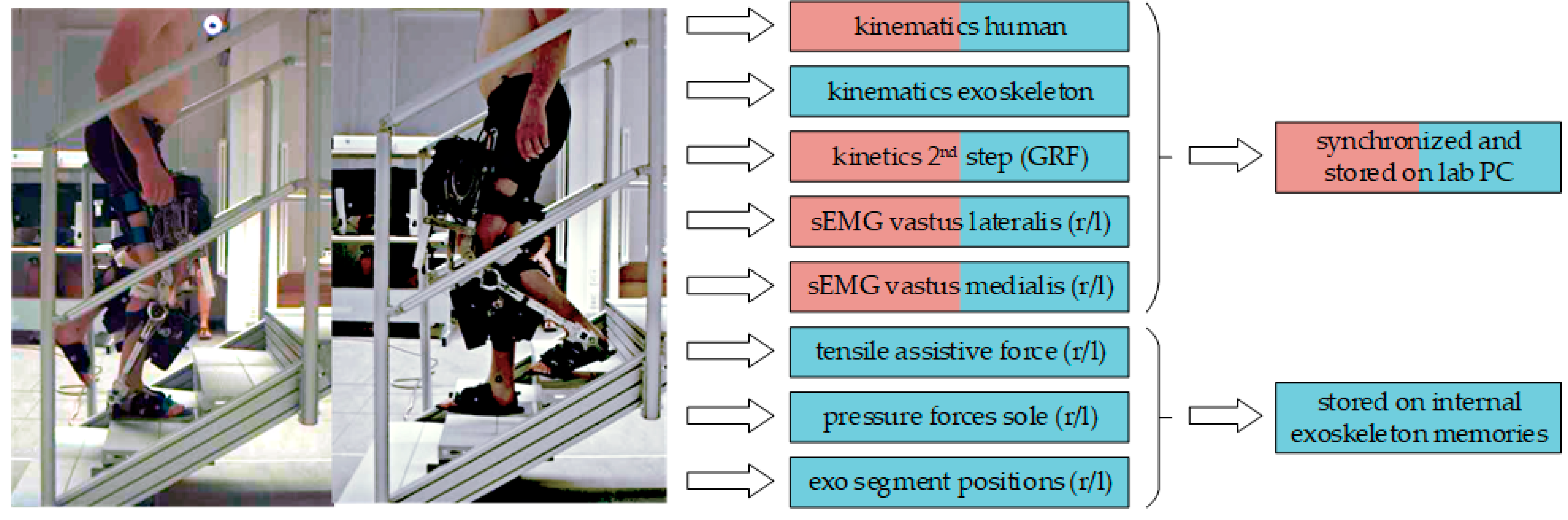
In order to investigate the biomechanical effectiveness of the novel exoskeleton system eBUS, all of the participants performed ascents and descents both without and with eBUS. For this purpose, a four-step staircase (Figure 3) with a step height of 0.16 m, tread of 0.28 m, and a resulting inclination angle of 30° was used. In the second step of the staircase is a force plate (MiniDyn type 9119AA2, Kistler Instrumente AG, Winterthur, Switzerland) is implemented to record the ground reaction force (GRF) at 1500 Hz. A marker-based motion capture system (Qualisys AB, Goteburg, Sweden) with twelve active infrared cameras recorded the kinematics at 100 Hz. For recording and synchronization, the software Qualisys Track Manager 2021 was used. The tensile assistive force in the Bowden cable was recorded through the tension force sensor, which is mentioned above. This force data, together with the data of the inertial measurement units for position determination and the pressure sensors for stands detection, were stored with a time stamp on the internal memories of the eBUS. Furthermore, sEMG signals of the m. vastus medialis (VAM) and m. vastus lateralis (VAL) were measured on both legs using dual electrodes and a wireless measurement system (Noraxon Inc., Scottsdale, AZ, USA).
Firstly, the relevant body parameters such as body weight, body height, and segment lengths were measured. Subsequently, the electrodes for the sEMG measurement were placed on the subject according to the seniam project [20]. After that, the subjects performed an isolated knee extension within a flexion angle of 90° to 70° to determine the maximum voluntary contraction (MVC) of the quadriceps femoris muscles according to [21]. Based on the CAST-model [22] and the placement of two markers on the shoulder, a total of 36 passive infrared markers were applied. Furthermore, eight additional markers were placed medially and laterally on the knee and ankle joints of both legs. The participants then performed six ascents and descents without the exoskeleton, barefoot, at a self-selected speed and climbing step-over-step.
In the second phase, the exoskeleton was adjusted according to the anthropometry of the participants (Table 2). Subsequently, the marker setup was adapted so that a total of 26 markers were attached to the human body and 18 markers were attached to each exoskeleton leg (Figure 4).
The eBUS, which was adjusted specifically for the subject, was attached to the subject’s legs under supervision and with the help of laboratory staff. Before the tests were carried out, the subject was able to familiarize him/herself with the attached eBUS and climbed the stairs several times without recording any data. The subject then performed a series of six ascents and descents at a self-selected speed, step-over-step, and without using the handrail.
2.3. Data Preparation, Modelling, and Calculations
After all data were recorded, a check of completeness and errors was carried out. In the first step, gaps in the trajectories of up to ten frames that were caused by the partial occlusion of markers by the test bed, were filled by polynomial interpolation using Qualisys Track Manager Version 2021. For markers belonging to a cluster, relational gap filling was used.
A moving average filter was used to improve the signal-to-noise ratio. The sEMG data with eBUS were generally noisier, so a filter length of 333 ms and 16.7 ms without the eBUS were used. Since MVC-normalized EMG-data showed values above 100% in two subjects, amplitude normalization to the within-trial peak value was performed for each subject and each movement task (ascent/descent; without and with eBUS). Subsequently, each sEMG dataset was time normalized in the stance phase between the start and end points that were marked in the dataset. To compare the subjects in each stance phase, we calculated the average of all of the sEMG datasets per subject. As we only had a limited number of datasets and there were some outliers, it was best to calculate the average using the median method. To compare the outliers per subject, the standard deviation was calculated and scaled and shown as a shaded area around the median. The scaling was necessary because the standard deviation was out of bounds in some datasets and was done using the square root function.
All of the movements without the eBUS were simulated using the Anybody Modelling System (AMS) (version 7.3.4, AnyBody Technology A/S, Aalborg, Denmark) [23]. A musculoskeletal model from the AnyBody Managed Model Repository (AMMR) (version 2.3.0) [24] without arms was used. The segment lengths were adjusted manually by using the specific subject data that were obtained from Table 1. In addition, the simplest muscle model in AMS was used. The measured data were then implemented, filtered with a low-pass filter (2nd order, 5 Hz Butterworth), and kinematically optimized [25] to calculate the joint angle curves. It was assumed that all of the markers have the same influence. The joint moments were calculated according to [26]. The calculation was automated using Python version 3.7 and the AnyPyTools package [27].
Subsequently, the data that were stored on the exoskeleton memories was synchronized with the data from the lab PC. For this purpose, the knee angle curve of both datasets was compared and synchronized. The force data that were measured with the tensile force sensor was then processed and used for the subsequent simulation with the eBUS. For this simulation, the CAD model of the eBUS was translated into an AMS script using the plug-in AnyExp4SOLIDWORKS version 1.2.0. The masses and inertias of the seven individual components of the eBUS per leg were taken into account accordingly. The exoskeleton model was attached to the human model that was described above with the help of dummy segments according to [28] and a contact model with virtual force plates [29]. The Bowden cable was modelled with endpoints and via points between the thigh and the shank of the exoskeleton to implement the assistive force through separate force files. The kinematics and kinetics were calculated in the same way as in the simulation without exoskeleton. The whole simulation model is shown in Figure 4 during the inverse calculation of a stair ascent.
Figure 4.
(a) Marker placement on the human and exoskeleton [29]. Markers on the human: two at the shoulders, four at the pelvis, four at the knees, six at the shanks, four at the ankles, and six at the feet. Markers on each exoskeleton leg: four at the thigh segment, three at the thigh rail, three at the shank segment, three at the shank lower rail, one at the foot rail, and four at the foot segment; (b) Human-exoskeleton-model during the inverse calculation of a stair ascent [4].

2.4. Analyses
For the evaluation of exoskeletons, muscle activities, joint moments, and joint reaction forces are often analyzed as simulation outputs [30,31]. A comprehensive evaluation of the exoskeleton should consider the effects of the system on the entire human body. For this reason, all of the angular curves of the lower extremities in sagittal and frontal planes, the moments of the hip, knee and foot, as well as the assistive moments that were applied by the exoskeleton in the knee are evaluated on a subject specific basis. Since the eBUS is designed to assist knee extension, the measured sEMG signals from VAL and VAM during the stance phase were also analyzed. The muscle activity is indicated as a percentage of the within-subject maximum. Furthermore, the joint reaction forces in the knee with and without eBUS were compared. The joint moments and the joint reaction force were normalized to the respective body weights.
All curves of angles, moments, and joint reaction forces are presented as a cycle for ascent and descent on a per-subject basis. The start of the cycle (0% cycle time) is defined by the first foot contact on the force plate with a threshold value of 20 N. The stance phase ends when the contact is released, and the swing phase begins at the same time. The end of the swing phase (100% cycle time) was determined by the marker trajectories. Each trial was trimmed, resampled, and linearly normalized to the duration of the stance respectively swing phase. The biomechanical results of each trial setting were averaged, standard deviated and plotted on the same graph.
The data that are summarized in Table 3 were simulated successfully and could be used for the analysis. Due to large gaps in the trajectories and incomplete data from the exoskeleton, not all six trials could be simulated for subjects 5 and 6 and were excluded from the analysis.
3. Results
The evaluation method that was used here can generate various results, but only a few relevant ones will be analyzed. As the exoskeleton actively assists the knee joint, we first present the assistive moment in the knee joint, that is the additional torque that is provided by the exoskeleton during the movements. Furthermore, the system has an influence on the kinematics of the subject during use, especially on the lower extremities. For this reason, the kinematic patterns of all three joints (hip, knee, foot) for sagittal and frontal planes were selected for evaluation. Since the eBUS influences not only the kinematics but also the kinetics, we also present the results of the joint moments in the sagittal plane. As the advantage of the applied analysis method is to calculate also the internal forces during the movement, the effect of the system on the knee joint reaction force was investigated. Finally, to determine the effect of the system, the measured sEMG signals of VAM and VAL were evaluated.
All of the curves are available as the mean with one standard deviation. The curves without the exoskeleton are displayed in red together with the curves with the exoskeleton in blue in the same graph.
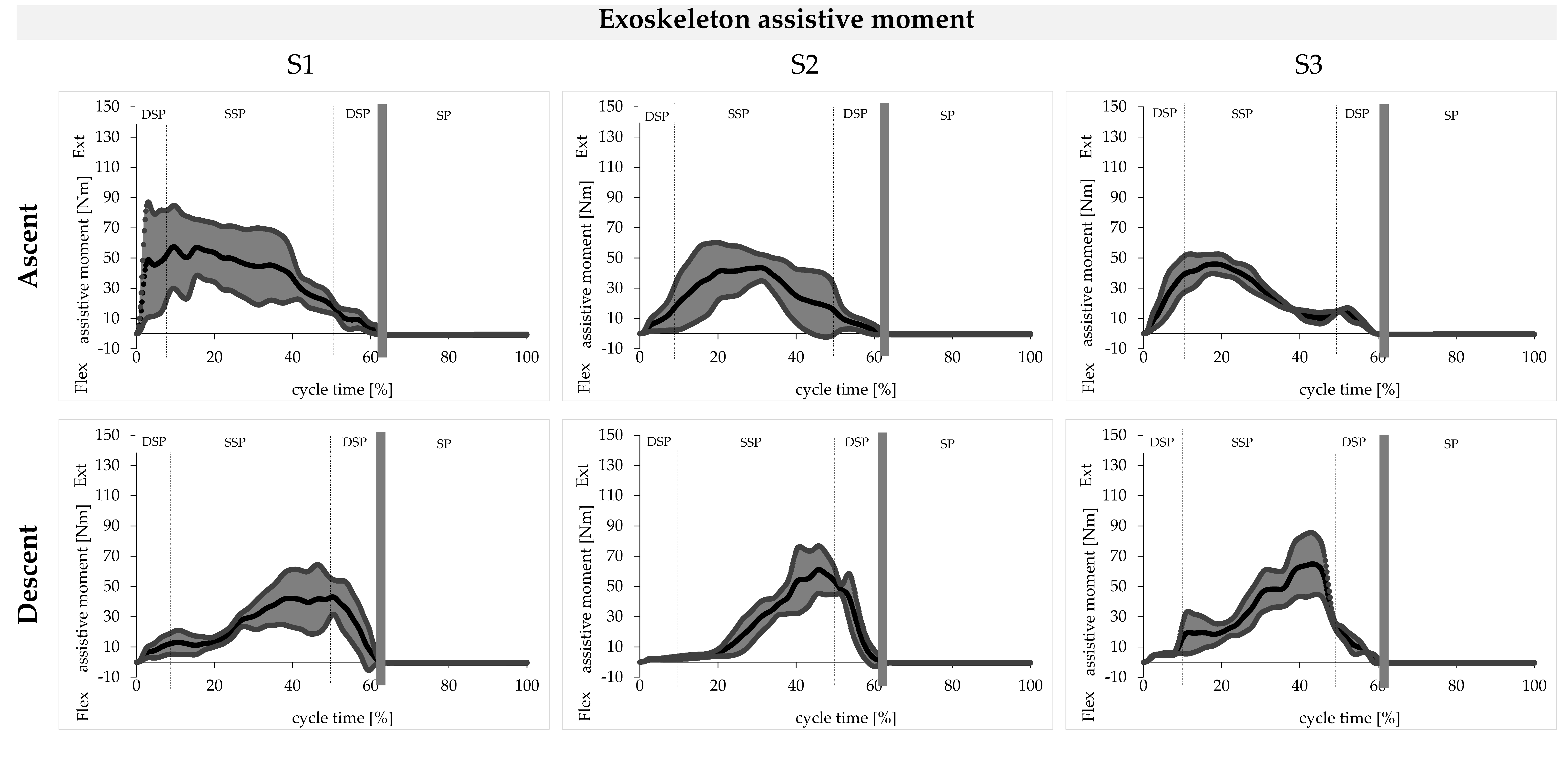
3.1. Assistive Moment in Knee Joint
The curves of the assistive moment for knee extension are shown for ascent and descent in Figure 5 for the tests with the eBUS as the mean (black) and with one standard deviation (grey). The mean curve of the eBUS moments is characterized by one peak for both movements. During the ascent, this peak occurs during the forward motion while during the descent it also occurs at the end of the stance phase during the subphase of controlled lowering. In the first subject, the eBUS generates a maximum torque of 60 ± 30 Nm during ascent and 45 ± 20 Nm during descent. For the other two subjects, these values are 45 ± 10 Nm each during the ascent and 60 ± 20 Nm during the descent.
3.2. Joint Angles in Sagittal Plane
The kinematic curves of the foot, knee, and hip angles in the sagittal plane are shown for ascent and descent in Figure 6 for the tests with the eBUS (blue) and without the eBUS (red). In general, we observe a high degree of similarity in the curves of the test persons. With the exoskeleton, the standard deviation is significantly greater, whereby individual differences become obvious.
Subjects 2 and 3 reduce the movement amplitude in the ankle joint by using the eBUS in ascent and descent. For the first subject, these angle curves are qualitatively similar for both movements, but still differ quantitatively. The largest average deviation of the curves with and without the eBUS occurs for Subject 2 during the descent in the swing phase with a value of 35°. However, the qualitative curves without the eBUS are intersubjectively similar for all three subjects. In both movements, the dorsal and plantar peaks of the curves without the eBUS are not achieved by the curves with the eBUS.
The knee angle curves with and without the eBUS are qualitatively similar for both movements of all three subjects. Quantitatively, the knee is flexed about 20° less with the eBUS during ascent over the entire cycle than without the eBUS. During descent, this effect occurs for all three subjects only in the first two phases until the controlled lowering at about 35% cycle time. In the swing phase, the knee is less flexed with the eBUS than without. The maximum flexion angles of the curves without the eBUS are not achieved in the trials with the eBUS for both movements in all three subjects.
The qualitative hip angle curves with and without the eBUS are similar for both ascent and descent. The exception to this is the phase of controlled lowering from 30 to 60% cycle time for the second subject during descent. In this phase, the second subject flexes his/her hip during the trials with the eBUS, so that the mean value is also beyond the standard deviation of the curve without the eBUS. For the first subject, the largest standard deviation of 20° occurs during the descent. The maximum flexion angle of 75° on average occurs in the second subject during the ascent with the eBUS and thus exceeds the maximum without the eBUS.
3.3. Joint Angles in Frontal Plane
The kinematic curves of the foot and hip angles in the frontal plane are shown for the ascent and descent in Figure 7 for the tests with eBUS (blue) and without the eBUS (red).
The angular curves of the subtalar eversion or inversion of the trials with the eBUS already differ qualitatively in all three subjects from the curves without the eBUS in both movements during most of the phases. However, all curves without the eBUS also differ from each other in an intersubjective comparison both qualitatively and quantitatively during ascent and descent. The same applies to the curves with the eBUS in the intersubjective comparison.
Both during ascent and descent, the adduction and abduction angle curves of the hip with the eBUS differ qualitatively and quantitatively from the curves without the eBUS in all three subjects. This is particularly noticeable in the phase of pulling up and forward as well as in the swing phase. It should also be noted that the qualitative curves without the eBUS are similar in the intersubjective comparison for the ascent, which also applies to the descent. The qualitative progressions for both movements with the eBUS are also similar in the intersubjective comparison.
3.4. Joint Moments in Sagittal Plane
The net joint moments of the foot, knee, and hip in the sagittal plane are shown for ascent and descent in Figure 8 for the tests with the eBUS (blue) and without the eBUS (red).
The curves of the foot or ankle moments without the eBUS are characterized by two peaks for both movements. The foot moment curves with the eBUS already differ qualitatively from those without the eBUS, since only one peak occurs here, except for the descent in Subject 3. Quantitatively, the foot joint moments that are applied without the eBUS, with mean maximum values of up to 1.6 Nm/kg, are significantly higher than the mean maximum values of 1.0 Nm/kg with the eBUS.
The results of the knee moment without the eBUS already show qualitative differences in the intersubjective comparison during the ascent. During descent, these curves without the eBUS are again similar. On the other hand, the knee moment curves with the eBUS are qualitatively different for each subject, which applies to the ascent and the descent. It is obvious during the descent in the trials with the eBUS that even flexion moments occur in all three subjects during the phase of controlled descent. In the trials without the eBUS, an extension moment always occurs in this phase. During descent, the quantitative maxima with the eBUS are significantly lower compared to the maxima without the eBUS. During the ascent, this again varies from subject to subject.
During the ascent, the curves of the hip moments coincide qualitatively and quantitatively in the phase of weight acceptance. In the subsequent phases, when the eBUS is used, the extension moment continues to increase for Subject 1 up to a cycle time of 45%, until a maximum of 1.3 ± 0.2 Nm/kg is achieved. For Subjects 2 and 3, a plateau is maintained here until the second double stance phase. Subsequently, the curve with the eBUS decreases more rapidly compared to the curve without the eBUS. The swing phase of the ascent with the eBUS is characterized by a lower flexion moment up to 80% cycle time. Subsequently, the flexion moment increases when using the eBUS until a maximum value of 0.5 ± 0.1 Nm/kg is achieved at the end of the cycle for all three subjects. During descent, the two trajectories differ both qualitatively and quantitatively in the most frequent phases for all three subjects. In the swing phase, the hip moment without the eBUS increases between 75 and 85% cycle time and then decreases again. In the swing phase, the hip moment curve with the eBUS is exactly the opposite of the curve without the eBUS.
3.5. Knee Joint Reaction Force
In the calculation of the knee joint reaction forces, the muscle forces that are involved in the movement, the masses and inertias of the human body and the exoskeleton, the measured ground reaction force, and the assisting force of the eBUS were taken into account besides the kinematics. The curves of the calculated joint reaction forces in the knee normalized to the body weight are shown accordingly in Figure 9 for the tests with the eBUS (blue) and without the eBUS (red).
The two peaks in the stance phase are characteristic for the ascent and descent, as it can be found in the curves without the eBUS. Compared to the stance phase, the swing phase is characterized by very low values with a maximum of 5 N/kg. Compared to the stance phase, the knee joint reaction forces during the swing phase are negligible.
However, when using the eBUS, the characteristic progression in the stance phase is not achieved in neither the ascent nor the descent. For both movements, only one peak occurs in the stance phase with values of 68 ± 10 N/kg during ascent and 35 ± 10 N/kg during descent. In comparison, the maximum values of Subjects 1 and 2 without the eBUS are about half as large during ascent. However, these values are comparatively similar during descent, and even 15 N/kg lower for Subject 2.
3.6. sEMG of Knee Extensor Muscles
The curves of the muscle activity of the knee extensor muscles (VAM and VAL) have a high degree of similarity in the contraction pattern as shown in Figure 10 for the tests with the eBUS (blue) and without the eBUS (red), which varies individually. The muscle activity varies greatly in individual cases with the eBUS, especially in Subject 1.
The measured muscle activities of VAM and VAL are characterized by two peaks in Subjects 2 and 3 during both movements without using the eBUS. In Subject 1, only one peak occurs at the beginning of the stance phase. When using the eBUS, the curve of both muscle activities during ascent is characterized by only one peak at the beginning of the stance phase. During descent, this peak occurs in the phase of controlled lowering with the use of the eBUS. Quantitatively, for all the subjects the maximum of the measured muscle activity during the trials with the eBUS is up to 50% lower than the maximum during the trials without. It should also be noted that for Subject 2 during descent in the phase of controlled lowering, the maximum values of both muscle activities with the eBUS are higher than the maximum values of the activities without the eBUS. The integrals of each sEMG curve are shown in Table 4 to highlight differences in the net effort of both muscles by using the eBUS. It becomes obvious that the values of all the subjects are lower when using the system, both for ascent and descent.
4. Discussion
The results that were obtained in the preliminary evaluation will now be discussed. In general, it can be postulated that the eBUS can significantly influence the climbing of stairs in three ways. Firstly, the additional masses of the eBUS have an influence on the dynamic human-machine system, which could result in a change in the kinematics and kinetics of human movements. The second influence relates to the restriction of the range of motion of the human locomotion system by the eBUS. Finally third, the tensile force transmitted from the eBUS to the human will most likely influence the human’s movement pattern, in an assistive manner in the desirable case. Within this discussion, only assumptions can be made about these influences, since the causal research of a potential change in movement was not the aim of this investigation. Rather, the results are to be interpreted in such a way that recommendations for further development of the evaluated eBUS can be derived and a general statement on the effect of the exoskeleton can be made.
4.1. Assistive Moment in Knee Joint
The assistive knee extension moment is applied by the eBUS during ascent in the phase of forward progression and during descent in the phase of controlled lowering. Therefore, in both ascent and descent, the phases with a power deficit that were identified by [3] could be assisted by the eBUS, as shown by the qualitative progression of the applied knee extension moment. Since the eBUS applied a maximum moment of 60 ± 30 Nm for the 76.5 kg Subject 1 (0.8 ± 0.4 Nm/kg) during the ascent, the exoskeleton that was presented here can compensate for the power deficit of 0.8 Nm/kg that was determined in [3]. The required assistive knee extension moments of 0.4 Nm/kg during the descent were also applied by the eBUS for all three subjects. It should be mentioned here that the selected drive can apply a cable force of 1500 N and thus a moment of 1.5 Nm/kg, so the maximum performance was not yet achieved during these tests.
4.2. Kinematics in Sagittal and Frontal Plane
The changes in the kinematics in the sagittal plane are significant in both movements due to the influence of the eBUS, because the angular curves with the eBUS are not within the standard deviation of the curves without the eBUS over the entire cycle in either the foot, knee, or hip joint. The qualitative trajectory can be maintained for the most part in the knee and hip joints. However, during descent in the controlled lowering phase, the hip becomes much more flexed when using the eBUS, as seen in Subjects 2 and 3. This could be interpreted as a compensatory movement for the lower dorsiflexion in the ankle. Since the freedom of movement in the hip joint is not affected by the eBUS, larger angular amplitudes can be achieved here, which favours an easier movement compensation via the hip. On the other hand, it can be noted that in the foot and knee joint the angular amplitudes are not achieved with the eBUS. This could be caused by the restriction of the freedom of movement by the eBUS, which is amplified by the potential misalignment of the joint axes between the human and the eBUS.
Since in the frontal plane all the mean angular curves of the foot are qualitatively altered by the eBUS in both movements and all three subjects, it could be postulated that this is due to a restriction of movement by the eBUS. In the hip joint, greater abduction occurs in the phase of pulling up and forward, especially during the ascent. During this phase, compensatory movements of the upper body were observed, which can presumably be attributed to the additional mass of the eBUS that is acting on the swing leg. During the stance phase, the subjects leaned laterally with their upper body over their own stance leg to facilitate the pulling up of the swing leg that was loaded with additional mass. Due to the larger abduction angle during the stance phase in the ascent, a smaller adduction angle is consequently required in the swing phase with the same experimental setup. This phenomenon can be confirmed by the measurement results. It can be concluded that the change in kinematics with the eBUS in the frontal plane is also significant.
4.3. Human Joint Moments
Human joint moments are influenced by the exoskeleton in various ways. On the one hand, the kinematics of the human exoskeleton system changes significantly, which is also reflected in longer stance times. On the other hand, the assistive moment of the eBUS influences at least the net knee moment of the human. Furthermore, the additional mass of the exoskeleton and the changed inertias of the lower musculoskeletal system influence the joint moments that must be generated.
For instance, the assisting extension moment in the knee also influences the foot moment that has to be generated by the user. On one hand, this is shown by only one peak in the curves with the eBUS and, on the other hand, by the reduction of the applied foot moment itself. Here, it can already be determined that the eBUS affects the subjects in different ways or that the subjects have different movement strategies when using the eBUS.
This assumption can be further confirmed by the curves of the applied knee moments, since the subjects with the eBUS also show different curves here. However, it can also be seen that the subjects have different knee moment curves even without the use of the exoskeleton, which suggests different movement strategies from the outset. Particularly noticeable is the change during the descent in all three subjects in exactly the phase in which the knee moment is assisted by the exoskeleton. In this phase, the required knee extension moment is even reduced to such an extent that the subjects generate a flexion moment to counteract the movement, as can be seen for Subject 3 especially. This could already indicate too much assistance by the system.
The hip moments to be applied by the human show a large discrepancy between the two test scenarios during the ascent in the phase of pulling up and forward. In these phases, the maximum extension moment is 1.4 ± 0.3 Nm/kg and could possibly be critical for the elderly. Presumably, this phenomenon has many causes. Firstly, an additional hip extension moment could be required to contribute potential energy to the additional mass of the eBUS during ascent. Secondly, the increased hip extension moment could be an indication of a redistribution of moments in favor of the hip in order to relieve the knee joint even more. Another cause for the change in hip moment could be the increased forward lean of the upper body during the trials with the eBUS. The exact causes of this phenomenon cannot be definitively answered at this point, as the changes in the kinematics due to the use of the eBUS must also be considered. For the hip moment that has to be generated in the swing phase, it can be stated that due to the additional mass of the eBUS, it is significantly higher compared to the tests without the exoskeleton, both for ascent and descent.
4.4. Knee Joint Reaction Forces
It was assumed that the joint reaction forces in the knee would decrease significantly through the use of the eBUS. This can neither be confirmed for the ascent nor for the descent by the results. In the descent, the mean value of the peak of the curve with the use of the eBUS is below the mean value without the eBUS only for Subject 2. During the ascent, the knee joint reaction force is even greater in all three subjects due to the use of the eBUS. The reason for this significant increase during ascent could be the misalignment of the knee joint axes between the human and the exoskeleton. These mismatches can cause additional shear loads in the knee joint and have to be compensated by the locomotion system [32].
Since the external moment of the eBUS is introduced from 20% to about 60% of the cycle time and at the same time the knee joint reaction force during ascent is significantly larger, it could be suspected that the additional moment of the eBUS influences the knee joint reaction force directly and even increases it. However, Stoltze and co-authors [33] figured out for level walking that the first peak of the knee joint reaction force is significantly influenced by the knee moment. On the other hand, the second peak is influenced by the foot moment, or gastrocnemius muscle, during the transition from single to double stance phase. In a pilot study, the authors were also able to demonstrate that an externally applied knee moment leads to a reduction of the knee joint reaction force in the first peak during level walking [34]. If these findings are also valid for stair climbing, only the first peak is lowered using the eBUS, as it is the case for the descent of the second subject. However, the qualitative curve of the knee joint reaction force with the eBUS is not characterized by two peaks, which is due to an acyclic movement.
4.5. Muscle Activity of Knee Extensors
Since all maxima of the muscle activities of the VAM and VAL were decreased using the eBUS, it could be concluded that the exoskeleton contributes to the relief of the knee extensors during ascent and descent. In addition to the maxima, the integrals of all the test persons were also reduced by using the eBUS according to Table 4. It can be concluded that the net effort of the test persons is lower when using the eBUS. Based on the integrals, the eBUS reduces the effort by an average of 19.3%. Thus, the performance deficit that is evaluated in [3] would be compensated by the exoskeleton. However, it should be noted that the presumed redistribution of joint moments in favour of the knee can also be the cause of the release of the knee extensors. However, this can only be postulated in this study, since no muscle activities of the gastrocnemius muscle nor of the hip flexors or extensors were measured.
A contradiction can be observed in the curves of the muscle activities compared to the knee moment curves and the assisting moment. The sEMG curves show a decrease in the muscle activity in the unassisted phases, while the activity in the assisted phases tends to remain the same. One reason for this could be the kinematics that have changed due to the eBUS. When using the eBUS, there might be a stronger backlift than leglift. Another cause could be passive assistance by the system itself in the phases in which it does not provide active assistance, although the measured muscle activities are decreased.
Furthermore, the measured muscle activities show that the subjects react individually to wearing and assistance by the exoskeleton. From this it can be concluded that not only an individual adjustment of the hardware of the exoskeleton is required, but also a control-related adjustment regarding the time of providing the assistance and the magnitude of the assisting moments.
5. Conclusions
In this pilot study it could be shown that the developed eBUS assists the ascent and descent of stairs. On one hand, this is indicated by the applied knee extension moment of the eBUS and, on the other hand, by the reduced muscle activities of the knee joint extensors. However, it also became evident that exoskeletons can affect subjects individually and should, therefore, be designed or adjusted to be subject-specific. This concerns, for example, the shape of the eBUS or its settings regarding segment lengths. Since the additional mass of the eBUS leads to compensatory movement of the upper body and the kinematics are significantly changed during both movements, the mass of the eBUS should be further reduced.
Since stair climbing is a comparatively slow movement with low angular velocities but large joint angles, assistance could be obtained for all three subjects. The results of this pilot study clearly show that a more individual application of force as well as an individual amount are required to provide adequate assistance. Furthermore, the goal of further optimizations of the system that is presented here should be to achieve shorter cycle times and a more cyclic movement.
Since the results in this pilot study are based only on the movement patterns of the subjects and the eBUS as well as on externally measured forces, additional sEMG measurements of all relevant muscles of the lower musculoskeletal system should be performed for future studies. This would also allow for the detection of subject-specific changes in movement strategies. Furthermore, an analysis of the joint power is useful in order to find out in which phases the human has to generate or absorb energy. A study with a larger number of subjects and trials would increase the statistical power. In subsequent studies, elderly people should also be tested, since they are the actual target group of the eBUS. In any case, further studies are necessary to investigate and ideally exclude potential damage to humans by the eBUS. For this purpose, it should be investigated, in particular, whether a redistribution of joint moments takes place as well as what effects the increase in the knee joint reaction force that is determined during the ascent has on humans.
All in all, it has been shown that the complex methods that are used here are suitable for evaluating the biomechanical function of exoskeletons. Other types of exoskeletons could also be evaluated with the methods that were used here.
Author Contributions
Conceptualization, J.J. and J.Z.; methodology, M.B.; formal analysis, M.B. and R.T.; investigation, M.B., H.-P.K., and M.W.; resources, M.W., J.J., and J.Z.; data curation, M.B. and H.-P.K.; writing—original draft preparation, M.B.; writing—review and editing, M.B., R.T., H.-P.K., J.J., and M.W.; visualization, M.B. and R.T.; supervision, M.W., J.J., and J.Z.; project administration, J.J. and J.Z.; funding acquisition, J.J. and J.Z. All authors have read and agreed to the published version of the manuscript.
Funding
This research was funded by Sächsische AufbauBank and the European Regional Development Fund (ERDF), grant number 3000917185. We acknowledge support by the Open Access Publication Funds of the HTWK Leipzig.
Institutional Review Board Statement
The study was conducted in accordance with the Declaration of Helsinki and approved by the Ethics Committee of University Leipzig (approved on 05 August 2021 with protocol code 2021.07.13_eb_107).
Informed Consent Statement
Informed consent was obtained from all subjects that were involved in the study.
Data Availability Statement
The data that are presented in this study are available on request from the corresponding author. The data are not publicly available due to privacy restrictions.
Acknowledgments
We would like to thank Felix Weiske, who developed the control system for the exoskeleton and played a key role in the data recording. We would also like to thank Julius Hannig, a member of the biomechanics laboratory at the University of Leipzig, who provided technical support during the study and helped with the data processing afterwards. Further thanks go to all study participants.
Conflicts of Interest
The authors declare no conflict of interest. The funders had no role in the design of the study; in the collection, analyses, or interpretation of data; in the writing of the manuscript, or in the decision to publish the results.
References
- ASTM F48 Committee. Terminology for Exoskeletons and Exosuits; ASTM International: West Conshohocken, PA, USA, 2020. [Google Scholar]
- Young, A.J.; Ferris, D.P. State of the Art and Future Directions for Lower Limb Robotic Exoskeletons. IEEE Trans. Neural Syst. Rehabil. Eng. 2017, 25, 171–182. [Google Scholar] [CrossRef] [PubMed]
- Böhme, M.; Weiske, F.; Jäkel, J.; Zentner, J.; Witt, M. Evaluation of the power deficit of elderly people during stair negotiation: Which joints should be assisted at least by an exoskeleton and with what amount? Wearable Technol. 2022, 3, E4. [Google Scholar] [CrossRef]
- Böhme, M. Untersuchungen zur Biomechanik und seniorengerechten Gestaltung von exoskelettalen Bewegungsunterstützungssystemen zur Überwindung von Treppen. Doctoral Thesis, Technische Universität Berlin, Berlin, Germany, 2022. [Google Scholar]
- Joudzadeh, P.; Hadi, A.; Alipour, K.; Tarvirdizadeh, B. Design and implementation of a cable driven lower limb exoskeleton for stair climbing. In Proceedings of the 5th RSI International Conference on Robotics and Mechatronics (IcRoM 2017), Tehran, Iran, 25–27 October 2017; IEEE: Piscataway, NJ, USA, 2018; pp. 76–81. [Google Scholar]
- Chandrapal, M.; Chen, X.; Wang, W. Preliminary evaluation of a lower-limb exoskeleton-stair climbing. In Proceedings of the 2013 IEEE/ASME International Conference on Advanced Intelligent Mechatronics (AIM 2013), Wollongong, NSW, Australia, 9–12 July 2013; IEEE: Piscataway, NJ, USA, 2013; pp. 1458–1463. [Google Scholar]
- Grimmer, M.; Riener, R.; Walsh, C.J.; Seyfarth, A. Mobility related physical and functional losses due to aging and disease—A motivation for lower limb exoskeletons. J. Neuroeng. Rehabil. 2019, 16, 2. [Google Scholar] [CrossRef] [PubMed]
- Jang, J.; Kim, K.; Lee, J.; Lim, B.; Shim, Y. Assistance strategy for stair ascent with a robotic hip exoskeleton. In Proceedings of the IROS 2016: 2016 IEEE/RSJ International Conference on Intelligent Robots and Systems, Daejeon, Korea, 9–14 October 2016; IEEE: Piscataway, NJ, USA, 2016; pp. 5658–5663. [Google Scholar]
- Deutsches Institut für Normung e.V. Gebäudetreppen–Begriffe, Messregeln, Hauptmaße; Beuth Verlag GmbH: Berlin, Germany, 2020. [Google Scholar]
- Zhao, S.; Yang, Y.; Gao, Y.; Zhang, Z.; Zheng, T.; Zhu, Y. Development of a soft knee exosuit with twisted string actuators for stair climbing assistance. In Proceedings of the IEEE International Conference on Robotics and Biomimetics, Dali, China, 6–8 December 2019; IEEE: Piscataway, NJ, USA, 2019; pp. 2541–2546. [Google Scholar]
- Zhang, Z.; Zhu, Y.; Zheng, T.; Zhao, S.; Ma, S.; Fan, J.; Zhao, J. Lower extremity exoskeleton for stair climbing augmentation. In Proceedings of the IEEE ICARM 2018—2018 3rd IEEE International Conference on Advanced Robotics and Mechatronics (ICARM), Sigapore, 18–20 July 2018; IEEE: Piscataway, NJ, USA, 2018; pp. 762–768. [Google Scholar]
- Zhao, X.; Chen, W.-H.; Li, B.; Wu, X.; Wang, J. An adaptive stair-ascending gait generation approach based on depth camera for lower limb exoskeleton. Rev. Sci. Instrum. 2019, 90, 125112. [Google Scholar] [CrossRef] [PubMed]
- Li, B.; Yuan, B.; Tang, S.; Mao, Y.; Zhang, D.; Huang, C.; Tan, B. Biomechanical design analysis and experiments evaluation of a passive knee-assisting exoskeleton for weight-climbing. Ind. Robot. Int. J. 2018, 45, 436–445. [Google Scholar] [CrossRef]
- Yuan, B.; Li, B.; Chen, Y.; Tan, B.; Jiang, M.; Tang, S.; Wei, Y.; Wang, Z.; Ma, B.; Huang, J. Designing of a Passive Knee-Assisting Exoskeleton for Weight-Bearing. In Intelligent Robotics and Applications; Huang, Y., Wu, H., Liu, H., Yin, Z., Eds.; Springer International Publishing: Cham, Switzerland, 2017; Volume 10463, pp. 273–285. [Google Scholar]
- Pott, P.P.; Wolf, S.I.; Block, J.; van Drongelen, S.; Grün, M.; Heitzmann, D.W.; Hielscher, J.; Horn, A.; Müller, R.; Rettig, O.; et al. Knee-ankle-foot orthosis with powered knee for support in the elderly. Proc. Inst. Mech. Eng. Part H J. Eng. Med. 2017, 231, 715–727. [Google Scholar] [CrossRef] [PubMed]
- Schmalz, T.; Colienne, A.; Bywater, E.; Fritzsche, L.; Gärtner, C.; Bellmann, M.; Reimer, S.; Ernst, M. A Passive Back-Support Exoskeleton for Manual Materials Handling: Reduction of Low Back Loading and Metabolic Effort during Repetitive Lifting. IISE Trans. Occup. Ergon. Hum. Factors 2022, 10, 7–20. [Google Scholar] [CrossRef] [PubMed]
- Fritzsche, L.; Galibarov, P.E.; Gärtner, C.; Bornmann, J.; Damsgaard, M.; Wall, R.; Schirrmeister, B.; Gonzalez-Vargas, J.; Pucci, D.; Maurice, P.; et al. Assessing the efficiency of exoskeletons in physical strain reduction by biomechanical simulation with AnyBody Modeling System. Wearable Technol. 2021, 2, E6. [Google Scholar] [CrossRef]
- Bell, A.L.; Brand, R.A.; Pedersen, D.R. Prediction of hip joint centre location from external landmarks. Hum. Mov. Sci. 1989, 8, 3–16. [Google Scholar] [CrossRef]
- C-Motion. Coda Pelvis: Visual3D Wiki Documentation. Available online: https://www.c-motion.com/v3dwiki/index.php?title=Coda_Pelvis (accessed on 4 July 2022).
- Hermens, H.J. European Recommendations for Surface ElectroMyoGraphy: Results of the SENIAM Project; Roessingh Research and Development: Enschede, The Netherlands, 1999. [Google Scholar]
- Konrad, P. EMG-Fibel: Eine Praxisorientierte Einführung in Die Kinesiologische Elektromyographie. Doctoral Thesis, Technische Universität Berlin, Berlin, Germany, 2011. [Google Scholar]
- Cappozzo, A.; Catani, F.; Della Croce, U.; Leardini, A. Position and orientation in space of bones during movement: Anatomical frame definition and determination. Clin. Biomech. 1995, 10, 171–178. [Google Scholar] [CrossRef]
- Damsgaard, M.; Rasmussen, J.; Christensen, S.T.; Surma, E.; de Zee, M. Analysis of musculoskeletal systems in the AnyBody Modeling System. Simul. Model. Pract. Theory 2006, 14, 1100–1111. [Google Scholar] [CrossRef]
- Lund, M.E.; Tørholm, S.; Jensen, B.K.; Galibarov, P.E.; Dzialo, C.M.; Iversen, K.; Sarivan, M.; Marra, M.A.; Simonsen, S.T. The AnyBody Managed Model Repository (AMMR). Zenodo 2020. [Google Scholar] [CrossRef]
- Andersen, M.S.; Damsgaard, M.; MacWilliams, B.; Rasmussen, J. A computationally efficient optimisation-based method for parameter identification of kinematically determinate and over-determinate biomechanical systems. Comput. Methods Biomech. Biomed. Eng. 2010, 13, 171–183. [Google Scholar] [CrossRef] [PubMed]
- Rasmussen, J.; Damsgaard, M.; Voigt, M. Muscle recruitment by the min/max criterion—A comparative numerical study. J. Biomech. 2001, 34, 409–415. [Google Scholar] [CrossRef]
- Lund, M.; Rasmussen, J.; Andersen, M. AnyPyTools: A Python package for reproducible research with the AnyBody Modeling System. J. Open Source Softw. 2019, 4, 1108. [Google Scholar] [CrossRef]
- Chander, D.S.; Böhme, M.; Andersen, M.S.; Rasmussen, J.; Cavatorta, M.P. Simulating the Dynamics of a Human-Exoskeleton System Using Kinematic Data with Misalignment Between the Human and Exoskeleton Joints. In Computer Methods, Imaging and Visualization in Biomechanics and Biomedical Engineering II: Selected Papers from the 17th International Symposium CMBBE and 5th Conference on Imaging and Visualization, 7–9 September 2021, 1st ed.; Tavares, J.M.R.S., Bourauel, C., Geris, L., Vander Slote, J., Eds.; Springer International Publishing: Cham, Switzerland, 2021; Volume 38, pp. 65–73. [Google Scholar]
- Chander, D.S.; Böhme, M.; Andersen, M.S.; Rasmussen, J.; Zentner, J.; Cavatorta, M.P. A comparison of different methods for modelling the physical human-exoskeleton interface. Int. J. Hum. Factors Model. Simul. 2021, 7, 204. [Google Scholar] [CrossRef]
- Tröster, M.; Wagner, D.; Müller-Graf, F.; Maufroy, C.; Schneider, U.; Bauernhansl, T. Biomechanical Model-Based Development of an Active Occupational Upper-Limb Exoskeleton to Support Healthcare Workers in the Surgery Waiting Room. Int. J. Environ. Res. Public Health 2020, 17, 5140. [Google Scholar] [CrossRef] [PubMed]
- Zhou, L.; Li, Y.; Bai, S. A human-centered design optimization approach for robotic exoskeletons through biomechanical simulation. Robot. Auton. Syst. 2017, 91, 337–347. [Google Scholar] [CrossRef]
- Plegge, C. Bedeutung und kinematische Untersuchung der Passform eines aktiven Exoskeletts für die untere Extremität. In Technische Unterstützungssysteme, DIE Die Menschen Wirklich Wollen: Zweite Transdisziplinäre Konferenz: Hamburg 2016; Weidner, R., Ed.; Laboratorium Fertigungstechnik smartASSIST Helmut Schmidt Universität: Hamburg, Germany, 2016; pp. 13–20. [Google Scholar]
- Stoltze, J.S.; Rasmussen, J.; Andersen, M.S. On the biomechanical relationship between applied hip, knee and ankle joint moments and the internal knee compressive forces. Int. Biomech. 2018, 5, 63–74. [Google Scholar] [CrossRef]
- Stoltze, J.S.; Pallari, J.; Eskandari, B.; Oliveira, A.S.C.; Pirscoveanu, C.I.; Rasmussen, J.; Andersen, M.S. Development and Functional Testing of an Unloading Concept for Knee Osteoarthritis Patients: A Pilot Study. J. Biomech. Eng. 2022, 144, 011007. [Google Scholar] [CrossRef] [PubMed]
Figure 1.
Novel exoskeleton robotic system to assist stair climbing called eBUS [4]: (a) attached to both legs in the frontal plane and (b) in the sagittal plane; (c) attached to the left leg in posterior view; (1) thigh segment, (2) thigh rail, (3) shank segment, (4) shank upper rail, (5) shank lower rail, (6) foot rail, and (7) foot segment.

Figure 2.
Adjustment possibilities on the eBUS exemplary for the left side (left) with a detailed view in the frontal plane (bottom right) and the adjustable distances (top right) [4]; D-A-K (Distance-Ankle-Knee); D-G-A (Distance-Ground-Ankle); D-TS-TR (Distance-ThighSegment-ThighRail); D-SS-SUR (Distance-ShankSegment-ShankUpperRail); D-FS-FR-lat (Distance-FootSegment-FootRail-lateral).

Figure 3.
Measured and stored data during stair ascents and descents with the novel exoskeleton system eBUS (bright blue). The red bares indicate data that are measured during stair ascent and descent without eBUS as a reference. r/l stands for right and left leg.
Figure 3.
Measured and stored data during stair ascents and descents with the novel exoskeleton system eBUS (bright blue). The red bares indicate data that are measured during stair ascent and descent without eBUS as a reference. r/l stands for right and left leg.

Figure 5.
Exoskeleton assistive moment in the knee joint to assist knee extension for Subject 1 (left), Subject 2 (middle), and Subject 3 (right); DSP = double stance phase, SSP = single stance phase, SP = swing phase.
Figure 5.
Exoskeleton assistive moment in the knee joint to assist knee extension for Subject 1 (left), Subject 2 (middle), and Subject 3 (right); DSP = double stance phase, SSP = single stance phase, SP = swing phase.

Figure 6.
Foot, knee, and hip angle curves in the sagittal plane for ascent and descent without (red) and with (blue) the exoskeleton for Subject 1 (left), Subject 2 (middle), and Subject 3 (right); DSP = double stance phase, SSP = single stance phase, SP = swing phase.
Figure 6.
Foot, knee, and hip angle curves in the sagittal plane for ascent and descent without (red) and with (blue) the exoskeleton for Subject 1 (left), Subject 2 (middle), and Subject 3 (right); DSP = double stance phase, SSP = single stance phase, SP = swing phase.

Figure 7.
Foot and hip angle curves in the frontal plane for ascent and descent without (red) and with (blue) the exoskeleton for Subject 1 (left), Subject 2 (middle), and Subject 3 (right); DSP = double stance phase, SSP = single stance phase, SP = swing phase.
Figure 7.
Foot and hip angle curves in the frontal plane for ascent and descent without (red) and with (blue) the exoskeleton for Subject 1 (left), Subject 2 (middle), and Subject 3 (right); DSP = double stance phase, SSP = single stance phase, SP = swing phase.

Figure 8.
Foot, knee, and hip moment curves in the sagittal plane for ascent and descent without (red) and with (blue) the exoskeleton for Subject 1 (left), Subject 2 (middle), and Subject 3 (right); DSP = double stance phase, SSP = single stance phase, SP = swing phase.
Figure 8.
Foot, knee, and hip moment curves in the sagittal plane for ascent and descent without (red) and with (blue) the exoskeleton for Subject 1 (left), Subject 2 (middle), and Subject 3 (right); DSP = double stance phase, SSP = single stance phase, SP = swing phase.

Figure 9.
Knee joint reaction force (proximal-distal) for ascent and descent without (red) and with (blue) the exoskeleton for Subject 1 (left), Subject 2 (middle), and Subject 3 (right); DSP = double stance phase, SSP = single stance phase, SP = swing phase.
Figure 9.
Knee joint reaction force (proximal-distal) for ascent and descent without (red) and with (blue) the exoskeleton for Subject 1 (left), Subject 2 (middle), and Subject 3 (right); DSP = double stance phase, SSP = single stance phase, SP = swing phase.

Figure 10.
sEMG curves of m. vastus medialis (VAM) and m. vastus lateralis (VAL) in stance phase for ascent and descent without (red) and with (blue) the exoskeleton for Subject 1 (left), Subject 2 (middle), and Subject 3 (right).
Figure 10.
sEMG curves of m. vastus medialis (VAM) and m. vastus lateralis (VAL) in stance phase for ascent and descent without (red) and with (blue) the exoskeleton for Subject 1 (left), Subject 2 (middle), and Subject 3 (right).


Table 1.
Relevant anthropometric data of the subjects with SID = subject identification, A = age in years, S = sex (m = male, f = female), bm = body mass [kg], bh = body height [m], hw = hip width [m], mtl = morphological thigh length [m], sl = shank length [m], fl = foot length [m].
Table 1.
Relevant anthropometric data of the subjects with SID = subject identification, A = age in years, S = sex (m = male, f = female), bm = body mass [kg], bh = body height [m], hw = hip width [m], mtl = morphological thigh length [m], sl = shank length [m], fl = foot length [m].
| SID | A | S | bm | bh | hw | Right Leg | Left Leg | ||||
|---|---|---|---|---|---|---|---|---|---|---|---|
| mtl | sl | fl | mtl | sl | fl | ||||||
| S1 | 31 | m | 76.5 | 1.76 | 0.171 | 0.486 | 0.426 | 0.257 | 0.494 | 0.412 | 0.260 |
| S2 | 24 | f | 62.2 | 1.72 | 0.176 | 0.428 | 0.412 | 0.265 | 0.442 | 0.400 | 0.267 |
| S3 | 23 | f | 71.8 | 1.69 | 0.186 | 0.458 | 0.386 | 0.248 | 0.445 | 0.387 | 0.248 |
Table 2.
Adjusted lengths of the exoskeleton to consider the anthropometry of each subject.
| Distances [mm] According to Figure 2 | Subject 1 | Subject 2 | Subject 3 | |||
|---|---|---|---|---|---|---|
| Left | Right | Left | Right | Left | Right | |
| D-TS-TR | 20 | 20 | 0 | 0 | 0 | 0 |
| D-A-K | 416 | 424 | 400 | 414 | 400 | 400 |
| D-SS-SUR | 136 | 136 | 133 | 135 | 133 | 135 |
| D-G-A | 78 | 78 | 78 | 78 | 80 | 79 |
| D-FS-FR-lat | 5 | 5 | 5 | 5 | 5 | 5 |
Table 3.
Analyzable data per subject (S1, S2, S3), movement (ascent, descent), and setting (with/without eBUS).
Table 3.
Analyzable data per subject (S1, S2, S3), movement (ascent, descent), and setting (with/without eBUS).
| Movement | Subject 1 | Subject 2 | Subject 3 | |||
|---|---|---|---|---|---|---|
| With eBUS | Without eBUS | With eBUS | Without eBUS | With eBUS | Without eBUS | |
| Ascent | 6 | 6 | 5 | 6 | 4 | 6 |
| Descent | 6 | 6 | 5 | 6 | 3 | 6 |
Table 4.
Integrals of the normalized median sEMG curves of m. vastus medialis (VAM) and m. vastus lateralis (VAL) in time normalized stance phase with and without the exoskeleton per subject (S1, S2, S3) and movement (ascent, descent).
Table 4.
Integrals of the normalized median sEMG curves of m. vastus medialis (VAM) and m. vastus lateralis (VAL) in time normalized stance phase with and without the exoskeleton per subject (S1, S2, S3) and movement (ascent, descent).
| Movement | Subject 1 | Subject 2 | Subject 3 | |||
|---|---|---|---|---|---|---|
| With eBUS | Without eBUS | With eBUS | Without eBUS | With eBUS | Without eBUS | |
| m. vastus medialis (VAM) | ||||||
| Ascent | 35.40 | 53.70 | 15.76 | 41.04 | 18.05 | 52.40 |
| Descent | 27.52 | 46.99 | 33.91 | 42.22 | 19.38 | 52.32 |
| m. vastus lateralis (VAL) | ||||||
| Ascent | 20.08 | 39.07 | 17.77 | 31.69 | 17.54 | 31.12 |
| Descent | 26.44 | 58.72 | 33.55 | 35.89 | 26.80 | 38.66 |
Publisher’s Note: MDPI stays neutral with regard to jurisdictional claims in published maps and institutional affiliations. |
© 2022 by the authors. Licensee MDPI, Basel, Switzerland. This article is an open access article distributed under the terms and conditions of the Creative Commons Attribution (CC BY) license (https://creativecommons.org/licenses/by/4.0/).
Share and Cite
MDPI and ACS Style
Böhme, M.; Köhler, H.-P.; Thiel, R.; Jäkel, J.; Zentner, J.; Witt, M. Preliminary Biomechanical Evaluation of a Novel Exoskeleton Robotic System to Assist Stair Climbing. Appl. Sci. 2022, 12, 8835. https://doi.org/10.3390/app12178835
AMA Style
Böhme M, Köhler H-P, Thiel R, Jäkel J, Zentner J, Witt M. Preliminary Biomechanical Evaluation of a Novel Exoskeleton Robotic System to Assist Stair Climbing. Applied Sciences. 2022; 12(17):8835. https://doi.org/10.3390/app12178835
Chicago/Turabian StyleBöhme, Max, Hans-Peter Köhler, Robert Thiel, Jens Jäkel, Johannes Zentner, and Maren Witt. 2022. "Preliminary Biomechanical Evaluation of a Novel Exoskeleton Robotic System to Assist Stair Climbing" Applied Sciences 12, no. 17: 8835. https://doi.org/10.3390/app12178835
Note that from the first issue of 2016, this journal uses article numbers instead of page numbers. See further details here.