
Influence of Pile Foundation Stiffness on Column Design in One-Story Reinforced Concrete Frames

Faculty of Geoengineering, University of Warmia and Mazury in Olsztyn, 10-957 Olsztyn, Poland
*
Author to whom correspondence should be addressed.
Appl. Sci. 2023, 13(5), 2915; https://doi.org/10.3390/app13052915
Submission received: 27 January 2023
/
Revised: 17 February 2023
/
Accepted: 21 February 2023
/
Published: 24 February 2023
(This article belongs to the Special Issue Structural Design and Analysis for Constructions and Buildings)
Abstract
:When designing reinforced slender columns for the lowest story of buildings, all factors that may affect the load-bearing capacity should be considered. One is the increase in the bending moment value caused by the rotation of the supporting foundation. The geotechnical parameters of subsoil stiffness and the method of calculating foundation displacements are the main influences. This problem applies to both shallow foundations and pile foundations. The article presents this issue in relation to pile foundations in multilayered subsoils and also the method and examples of second-order calculations that take into account the influence of pile support and columns’ nominal stiffness. The results showed that taking into account the stiffness of the pile foundation has an impact on the increase in bending moments in the columns, and this cannot be ignored in the design. The presented method allows for a precise, safe and optimal design of concrete columns supported by foundations on multilayered subsoils.
1. Introduction
The absence of slenderness restrictions in Eurocode 2 [1] and the use of increasingly better materials make it possible to design slimmer columns than in the past, but this involves more careful analyses and, according to Section 5.8.7 of Eurocode 2 [1], “where relevant, soil-structure interaction should be taken into account”. The importance of the interaction between the soil and the structural system of various structures has been demonstrated in many works, for example, in [2,3]. The influence of slenderness in the calculation of reinforced concrete columns is the subject of many scientific publications [4,5,6,7]. The paper from [8] analyzed the safety level of the calculation, and [9,10] dealt with the determination of the lower limit above which the influence of slenderness is significant.
Column deflections due to first- and second-order effects cause increments in the eccentricities of longitudinal forces and, thus, increments in the bending moments in the columns. Foundation rotations result in additional increments of the moments, which can be significant in some structures. The stiffness of pile foundations is known to increase with rotation. Therefore, the authors of this paper decided to analyze the effect of pile foundation stiffness on the increment of moments in columns of reinforced concrete single-story frames.
The increments of moments associated with second-order effects can be calculated through the use of the simplified method or the general method. The simplified method is based on the concept of isolated elements, in which the reinforced concrete columns of single-story halls are calculated according to the current valid provisions of Eurocode 2 [1]. The design length l0 should be taken as for cantilevers (i.e., l0 = 2lcol) because there are no provisions in [1] that allow for a different length to be taken. On the other hand, based on the presented analyses, among others, in [11], in a single-story hall building with columns restrained in the footings and pinned to the roof structure, the buckling length factor for each column is 2.0 only if the stiffness ratios of the columns EI to the longitudinal forces NEd occurring in them are the same. This condition cannot always be met in the design, so taking µ = 2.0 for each column will not always be correct. The problem of calculating design lengths is primarily concerned with the simplified method. Formulas to determine the effective lengths of separated columns have been developed in papers [12,13].
In principle, the application of the general method does not require the design lengths to be determined, as the shape of the deformed elements and the associated increase in the moments are determined directly in the calculations. For this reason, it is recommended to use the strict method for designs, which consists of a second-order analysis that takes into account the nominal stiffnesses (the calculation methods are described in papers [11,14,15]).
2. Consideration of Subsoil Stiffness in the Design of Reinforced Concrete Hall Columns
In order to determine the foundation rotation in the static calculations of the frame, a fictitious column support model can be taken as the column support with a scheme as in Figure 1b and with a length L and a stiffness EI chosen so that its flexural stiffness 3EI/L satisfies the relation in the following formula:
where
- IF—moment of inertia of the foundation base field;
- Cz—coefficient of elasticity of the subsoil.
Figure 1.
(a) Foundation on resilient ground; (b) pile foundation; (c) how ground influence is modeled in static calculations of foundations.
Figure 1.
(a) Foundation on resilient ground; (b) pile foundation; (c) how ground influence is modeled in static calculations of foundations.

The coefficient Cz is not a soil material constant, as it depends not only on the physical properties of the soil but also on the dimensions of the foundation. Using the works of Gorbunov-Posadov [16] and Levinsky [17] on soil as a homogeneous elastic half-space with characteristics defined by the modulus E0 and the Poisson’s ratio ν0, the coefficient Cz can be calculated from the following formula:
where 2l is the width of the foundation and b′ is its length (Figure 1).
Given that
the formula is as follows:
The angle of rotation φ at the support of the fictitious bar, which is induced by the moment M, can be calculated from the following formula:
In the case of pile foundations, the rotation angle φ does not depend on the stiffness of the soil in a simple, direct manner. This is due to the specifics of using pile foundations and the factors on which the mechanical response of the piles comprising the foundation depends. Generally speaking, pile foundations are used in the presence of an unfavorable subsoil when shallow foundations do not ensure that the required limit state conditions are met for an economically justified structural solution. The calculation model in these situations requires the adoption of a geotechnical profile where the subsoil is divided into layers with appropriately selected parameters. The value of the rotation angle φ is obtained by calculating the settlement of the individual piles in the foundation and taking into account their arrangement. Then, using Equation (5), the following relationship is obtained:
which allows for the creation of a column support model by assuming a fictitious bar of length L and stiffness EI. The main problem in this case will be the choice of an appropriate method for calculating the settlement of single and in-group piles.
3. Method for Calculating Pile Foundation Settlement
A foundation pile loaded by an axial force transmits a load to the surrounding soil medium due to shear resistance mobilized at the side of the pile and at the pile base resistance (Figure 2). The magnitude of resistance mobilized at the side of the pile in the individual layers and under the base of the pile can be related to the magnitude of the displacement (strain). This relationship is described by load transfer functions (σ − z; τ − z), as shown in Figure 2. To date, many proposals for load transfer functions have been developed and described mathematically on the basis of empirical results and theoretical solutions [18,19,20,21,22,23,24].
In numerical modeling, the load transfer functions represent the stiffness characteristics of the elastic support, which reflect the mobilized resistance of the surrounding subsoil (Figure 2). After discretization of the pile model, the values of the forces generated at the individual nodes and node displacements are obtained as a result of a numerical procedure.
The calculations for successive load increments produce non-linear settlement (load) curves that characterize the behavior of the pile over the full range of its loading (Figure 3).
According to the above scheme, the calculation represents an approach for the design of pile foundations that abandons the classic concept of pile bearing capacity expressed in terms of force and gives more weight to the amount of settlement by obtaining the load–settlement (Q–s) characteristics of the pile. This design concept is easier to apply than the classical approach. An example of such an approach is a method based on theoretical load transfer functions [20,21] by Bateman et al. [25]. The empirical load transfer functions are of limited use, while the theoretical functions are more attractive because of the universality of the solution, which is the approach used in the method presented in [26,27].
In foundations that are a group of piles, the interaction between the piles must additionally be taken into account. This is a significant issue in itself [28,29,30,31], but with the use of the load transfer function method, it is reduced to a modification of the original function for a single pile.
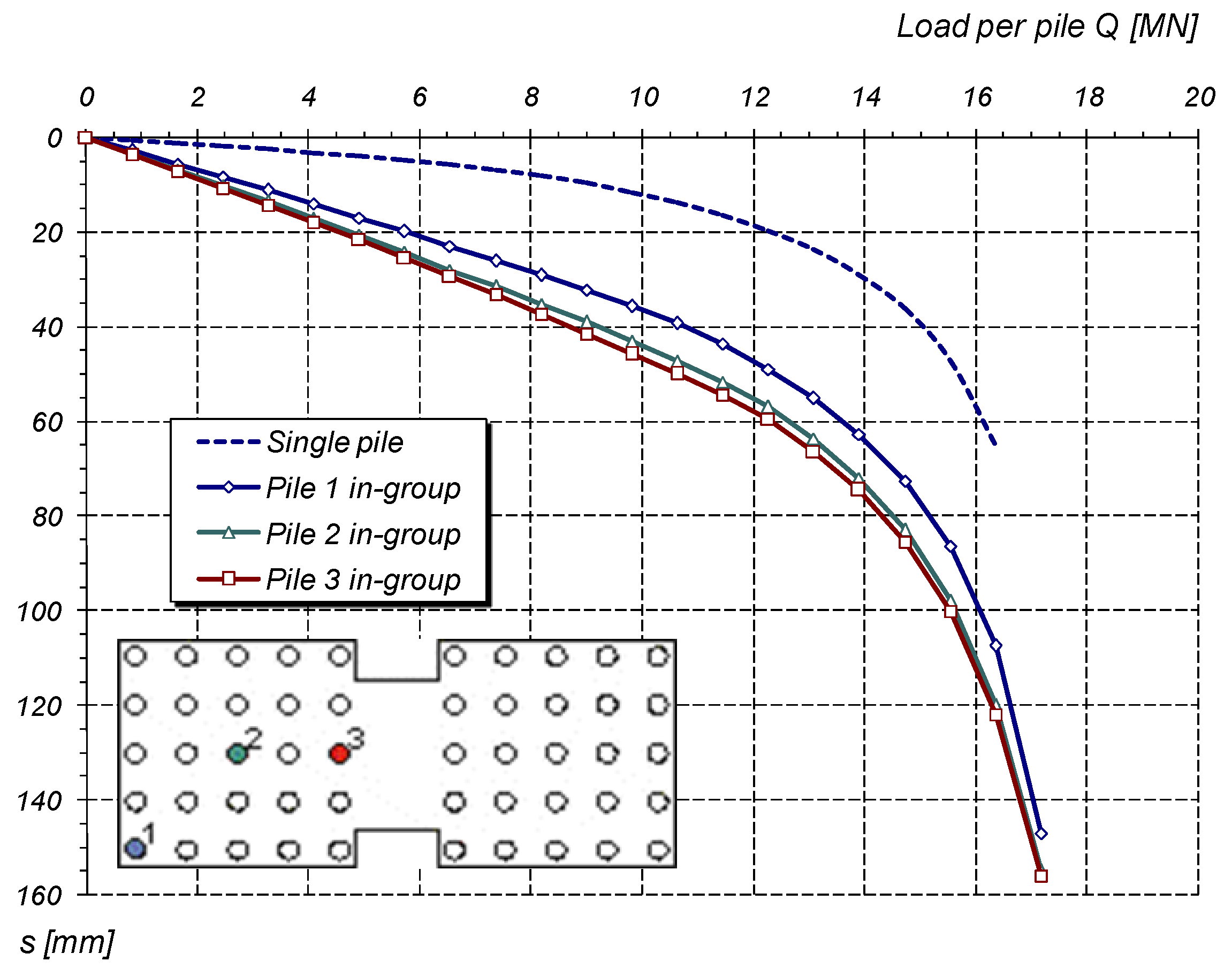
The settlement of adjacent piles is due to the settlement of a single pile loaded by an axial force and the interaction between the piles. This results in higher settlements of piles in a group (sij) compared to settlements of the same piles considered as single piles (si, sj), as shown in Figure 4.
If the foundation rests on a group of n piles, the settlement of the i-th pile, taking into account the interaction between the piles, is calculated according to the following formula:
where
- si—settlement of the single pile i under the load Qi;
- sij—settlement of the pile pair i and j loaded with the forces Qi and Qj.
It follows that the multiple pile settlement will be greater than that of a single pile settlement if more piles interact with each other; see the example in Figure 5.
To calculate the settlement of piles in a group, a method is proposed [26,27], which is based on the idea of the hybrid method presented by Chow [32]. For single piles, the method uses a solution to create non-linear foundation pile settlement curves. The method was developed and improved on the basis of analyses of the results of studies on non-linear soil behavior and test loads on piles under field conditions.
In the single pile analysis method, a non-linear elastic–plastic model was used to reflect the non-linear behavior of the pile before reaching the ultimate bearing capacity in the pile–soil contact zone. The non-linear behavior of the pile was represented by functions describing the change in the value (degradation) of the shear modulus as a function of mobilized soil resistance or strain.
In the method’s algorithm, the pile described by Young’s modulus of elasticity is digitized through the use of the adopted load transfer function. For the pile shaft, the characterization of the supports is based on the following solution proposed by Randolph and Wroth [20]:
where
- ss—displacement of the nodal point of the pile sidewall;
- τ0—tangent stress on the side of the pile;
- R0—radius of the pile shaft;
- Rmax—range of influence of the pile;
- Gs—shear modulus of the soil in the vicinity of the pile shaft.
The radius of influence of the pile Rmax can be calculated according to Van Impe and De Clercq’s equation [33], which is as follows:
where
- Lp—length of the pile in the subsoil;
- z—depth below ground level;
- ν—Poisson’s ratio.
The deflection of the support under the pile base (base settlement) sb under the force Pb based on the theory of elasticity is described by the following equation:
where
- Rb—pile base radius;
- Gb—shear modulus of the soil under the base of the pile;
- νb—Poisson’s ratio;
- µd—impact factor of base depth, µd = 0.5.
In the above equations, the shear modulus G decreases according to the degradation function adopted.
Initially, the method described here adopted a modified form of the hyperbolic modulus degradation function G according to Kraft [21] as proposed by Chow [32]:
where
- Gmax—initial shear modulus;
- τ—current, mobilized soil resistance;
- τf—limit soil resistance (at failure);
- Rf—hyperbolic curve constant, Rf = 0.5 ÷ 0.9.
Subsequent modifications were used, among other functions:
- according to Van Impe and De Clercq [33]:
- according to Fahey and Carter [34]:
- Gmax—initial shear modulus;
- w—equation parameter.
Figure 6 shows the selected functions on a graph for comparison.
The application of the numerical procedure allows for the load–settlement curve for a single pile to be determined. In addition, the results make it possible to divide and analyze the total load into the part carried by the sidewall and the base for successive load degrees on the pile head.
The computational model of the subsoil is characterized by geotechnical layers, which are described by the initial shear modulus Gmax, limit shear resistance at the shaft τf and limit resistance under the pile base qf. These parameters can be determined, for example, by an indirect method based on the results of a CPT probe test [35,36]. The selection of a suitable degradation model requires extensive analytical studies with the use of geotechnical test results and settlement curves from pile test loads [37]. Test interpretation issues for determining the initial shear modulus Gmax and its degradation are presented in [38].
In the examples presented below, the degradation curves for the shaft Equation (13) and for the base Equation (12) are used. The interaction between the piles is taken into account through the use of the classical solution of elasticity theory.
4. Examples
Examples of calculations of bending moments in reinforced concrete frame columns are shown below. The calculations were carried out using the rigorous method of second-order analysis with nominal stiffnesses, as described in [15]. The calculations were conducted for both fully restrained columns and columns fixed in a piled foundation. The columns were assumed to have equal cross-sections of b = 0.40 m and h = 0.45 m and were made of concrete C30/37 and steel RB500.
For comparison purposes, we assumed the same geotechnical conditions (Figure 7; Table 1), which were the same for all the structural variants analyzed. The pile supports under the columns were adopted in the form of reinforced concrete rectangular pile caps topping the heads of two piles with an axial spacing of sp = 1.2 m. The pile types were reinforced concrete piles, prefabricated, driven and with a square cross-section of 0.35 × 0.35 m.
The lengths of the piles varied (Lp = 10, 14 and 15 m), as they were selected according to the assumptions of the limit state method in order to obtain a similar degree of bearing capacity reserve in each case (ensuring fulfillment of the limit state condition for piles loaded with compressive forces). Figure 8 shows the settlement curves of the assumed piles obtained from the calculations.
The calculation of the stiffness of the column/foundation connection was based on the calculation of pile settlements in the column support, taking into account the interaction between the two according to the method outlined above.
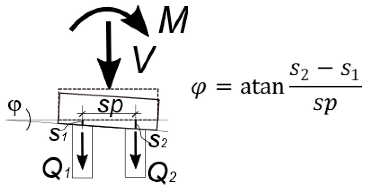
The resulting rotation angle φ allows for the static calculation of the column to be carried out, taking into account the second-order theory. Considering the stiffness of the pile support leads to new values for the internal forces and nodal forces (reactions). The described procedure requires iterative calculations according to the following scheme:
- (I)
- Static calculation of the hall’s structural system, assuming that the columns are restrained at their supports and obtaining nodal forces;
- (II)
- Determination of the pile loads Qi, verification of the ultimate limit state of the pile, calculation of the pile settlement and foundation rotation (Figure 9);
- (III)
- Making a static calculation of the hall’s structural system according to the second-order theory, taking into account the rotational stiffness of the pile supports and obtaining new values for the nodal forces;
- (IV)
- Determination of new loads on the pile Qi, verification of the ultimate limit state of the pile, calculation of pile settlement and foundation rotation as in step (II).
Steps (II)–(IV) are performed until the results converge. The calculations performed for the example presented here required two or three iterations.
Figure 9.
Diagram for calculating settlement and rotation of pile foundations. Q1, s1—load and settlement of pile 1; Q2, s2—load and settlement of pile 2; sp—axial spacing of the piles.
Figure 9.
Diagram for calculating settlement and rotation of pile foundations. Q1, s1—load and settlement of pile 1; Q2, s2—load and settlement of pile 2; sp—axial spacing of the piles.

4.1. Example 1
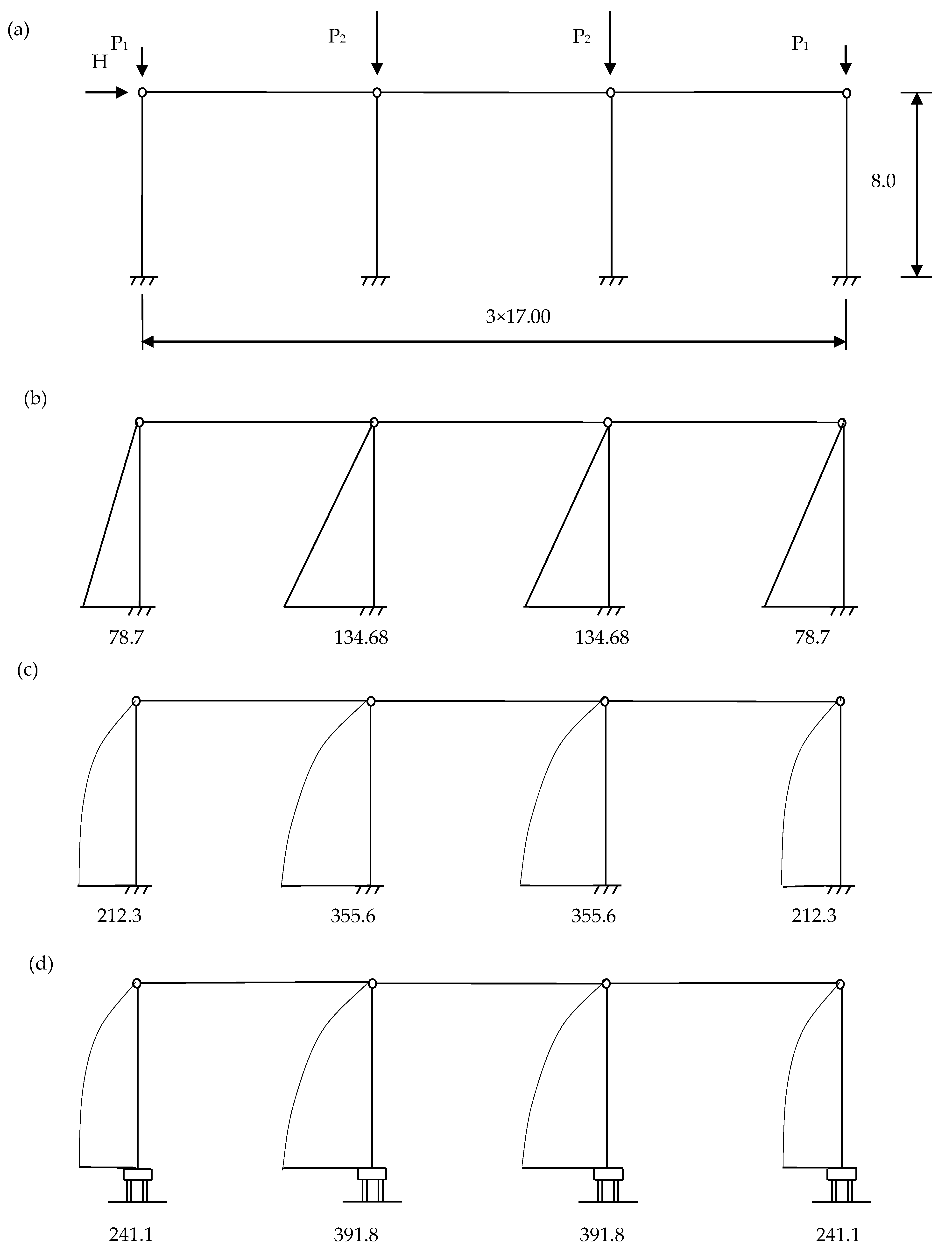
The design longitudinal forces in the columns of the three-aisle hall (Figure 10) are each P1 = 500 kN in the outermost columns and P2 = 1000 kN in the inner columns. The horizontal force due to wind pressure and suction is H = 45 kN. The rigid roof structure is assumed to force equal horizontal displacements of the upper ends of all columns. A reinforcement of 3ϕ25 mm (As = 14.73 cm2) was assumed in the end columns and 5ϕ25 mm (As = 24.55 cm2) in the inner columns on each side of the section; a = 4.8 cm.
The detailed nominal stiffness calculations for Example 1 are shown in Appendix A.
The result of the calculation according to the first-order theory with nominal column stiffnesses is shown in Figure 1b, and the result of the calculation according to the second-order theory is shown in Figure 10c.
The nodal reaction values obtained assuming full restraint in the support are used to calculate the forces and displacements of the pile support. The subsequent calculations are carried out in an iterative manner. Table 2 summarizes the results of the calculations for the first and last iterations, and the final values of moments in the supports are shown in Figure 10d.
4.2. Example 2
The design longitudinal forces in the columns of the two-bay hall (Figure 11) are each P1 = 400 kN in the outermost columns and P2 =1000 kN in the inner columns. The horizontal force due to wind pressure and suction is H = 40 kN. The eccentricity of the reaction from the diagonal load in the outermost columns is equal to 0.15 m. It was assumed that the rigid roof structure forces equal the horizontal displacement of the upper ends of all columns. A reinforcement of 4ϕ20 mm (As = 12.56 cm2) was assumed in the end columns and 7ϕ20 mm (As = 21.98 cm2) in the inner columns on each side of the section; a = 4.0 cm. The detailed nominal stiffness calculations for Example 2 are shown in Appendix B.
The result of the calculation according to the first-order theory with nominal column stiffnesses is shown in Figure 11b, and the result of the calculation according to the second-order theory in shown in Figure 11c. Table 3 summarizes the results of the pile support calculations for the first and last iterations, and the final values of the moments in the supports are shown in Figure 11d.
5. Discussion
The examples show calculations for stratified soil with low stiffness. In general, the influence of ground compliance on the bending moments is not large. In Example 1, the differences in the bending moments between full restraint and strict calculation, including pile foundation, exceed 10%. In Example 2, these differences are large for only one outermost column. As a result of taking the elastic foundation into account, the bending moment in this column has increased by approximately 20% compared to the calculation with full restraint.
The work presented here is a continuation of earlier analyses of single-story frames with piles founded in various conditions. The examples presented were limited to one-story frames founded on piles for the adopted geotechnical conditions. Future research should focus on comparative analyses of other structural systems and other geotechnical conditions.
6. Conclusions
- The paper presents a method for modeling the support of a column fixed in a pile-founded footing. The originality of the method is to take into account the non-linear behavior of piles through the use of the degradation function of the stiffness modulus of the soil in the application to the calculation of bending moments in columns.
- Example frame calculations were carried out with the rigorous method of the second-order analysis with nominal stiffnesses, modeling the column support conditions as described in the paper. Rotation of the foundation leads to increased ultimate moments in the columns, which can be important in some cases of slender column foundations.
- In the case of pile foundations, the effect of the increase in the moments is smaller than for shallow foundations [15] and should not be omitted from the calculations. In more complex cases, accurate calculations, as in the presented examples, should be used for the dimensioning of the reinforcement in the columns rather than the simplified methods used for separated columns, according to Eurocode [1].
- The proposal allows for a more rational design of similar structures compared to standard simplified methods. The example presented should be considered strictly in relation to the conditions adopted in it. The adopted structural system, the loading, type, number and spacing of the piles and the geotechnical conditions will all affect the results obtained.
- Piles should be designed for the ultimate forces obtained according to the second-order theory, especially for the design of slender columns.
- Piles should be designed for both ultimate limit state conditions and displacement limitation conditions. Knowledge of the predicted mechanical characteristics (Q–s settlement curves) of pile supports enables more rational static calculations of the entire structural system of the structure.
Author Contributions
Conceptualization, I.D. and K.K.; methodology, I.D. and K.K.; software, I.D. and K.K.; validation, I.D. and K.K.; formal analysis, I.D. and K.K.; investigation, I.D. and K.K.; resources, I.D. and K.K.; writing—original draft preparation, I.D. and K.K.; writing—review and editing, I.D. and K.K.; visualization, I.D. and K.K.; supervision, I.D. All authors have read and agreed to the published version of the manuscript.
Funding
This research received no external funding.
Institutional Review Board Statement
Not applicable.
Informed Consent Statement
Not applicable.
Data Availability Statement
All data, models that support the findings of this study are available from the corresponding author upon reasonable request.
Conflicts of Interest
The authors declare no conflict of interest.
Appendix A
The imperfections according to Section 5.2 of Eurocode 2 [1] are as follows:
The pillar angle .
Horizontal forces caused by the imperfections:
- in the end columns ;
- in the center columns .
The nominal stiffnesses (Section 5.8.7.2 of Eurocode 2 [1]) depend on the amount of reinforcement. When designing the columns, reinforcement must be assumed in order to calculate the enlarged bending moments and, based on these moments, the reinforcement needed. The result is, therefore, obtained with an iteration method once a reasonable level of agreement between the assumed and calculated reinforcements has been achieved.
Design modulus of elasticity of concrete Ecd = 26,670 MPa, and moment of inertia Ic = 3.038 × 10⁻³ m4.
For l0 = 2lcol = 2 · 8 = 16.0 m, the radius of inertia .
The slenderness .
The effective creep coefficient was assumed to be φef = 2.4.
The coefficient k2 for the end columns is as follows:
The moment of inertia of the reinforcement is as follows:
The coefficient Kc = k1 k2/(1 + φef) = 1.225 · 0.1/(1 + 2.4) = 0.036 and Ks = 1.
The nominal internal column stiffness is as follows:
EI = KcEcdIc + KsEsIs = 0.072 · 26,670 · 3.038 · 10−3 + 1.0 · 200 · 103 · 15.38 · 10−5 = 36.59 MNm2.
Appendix B
The imperfections according to Section 5.2 of Eurocode 2 [1] are as follows:
The pillar angle .
Horizontal forces caused by imperfections:
- in the end columns ;
- in the center columns .
The calculations were performed as in Example 1.
For l0 = 2lcol = 2 · 8 = 16.0 m, the radius of inertia .
The slenderness .
The effective creep coefficient was assumed to be φef = 2.4.
The coefficient k2 for the end columns is as follows:
The moment of inertia of the reinforcement is as follows:
The coefficient Kc =k1 k2/(1 + φef) = 1.225 · 0.08/(1 + 2.4) = 0.029 and Ks = 1.
The nominal stiffness of the end columns is as follows:
EI = KcEcdIc + KsEsIs = 0.029 · 26,670 · 3.038 · 10−3 + 1.0 · 200 · 103 · 8.60 · 10−5 = 19.55 MNm2.
The coefficient k2 for the inner columns is as follows:
Kc = k1 k2/(1 + φef) = 1.225 · 0.08/(1 + 2.4) = 0.029 and Ks = 1.
The moment of inertia of the reinforcement is as follows:
The nominal stiffness of the internal column is as follows:
EI = KcEcdIc + KsEsIs = 0.072 · 26,670 · 3.038 · 10−3 + 1.0 · 200 · 103·15.04 · 10−5 = 35.91 MNm2.
References
- EN 1992-1-1; Eurocode 2: Design of Concrete Structures. Part 1-1. General Rules and Rules for Buildings. European Committee for Standardization: Brussels, Belgium, 2004.
- Zucca, M.; Crespi, P.G.; Longarini, N.; Scamardo, M.A. The new foundation system of the Basilica di Collemaggio’s transept. Int. J. Mason. Res. Innov. 2020, 5, 67–84. [Google Scholar] [CrossRef]
- Gonzáleza, F.; Carbonarib, S.; Padróna, L.A.; Moricic, M.; Aznáreza, J.J.; Dezid, F.; Maesoa, O.; Leonic, G. Benefits of inclined pile foundations in earthquake resistant design of bridges. Eng. Struct. 2020, 203, 109873. [Google Scholar] [CrossRef]
- Klempka, K.; Knauff, M. Design of slender RC columns according to Eurocode and polish code compared with the improved numerical model. Arch. Civ. Eng. 2005, 51, 23–42. [Google Scholar]
- Hamed, E.; Lai, C. Geometrically and materially nonlinear creep behaviour of reinforced concrete columns. Structures 2016, 5, 1–12. [Google Scholar] [CrossRef]
- Gilbert, R.I.; Ranzi, G. In-service deformations of reinforced concrete columns in biaxial bending. In Proceedings of the Twelfth East Asia-Pacific Conference on Structural Engineering and Construction, Hong Kong, China, 26–28 January 2011. [Google Scholar]
- Kim, C.S.; Gong, Y.; Zhang, X.; Hwang, H.J. Experimental study on long-term behavior of RC columns subjected to sustained eccentric load. Adv. Concr. Constr. 2020, 9, 289–299. [Google Scholar]
- Strauss, A.; Hauser, M.; Täubling, B.; Ivanković, A.M.; Skokandić, D.; Matos, J.; Galvão, N.; Benko, V.; Dobrý, J.; Wan-Wendner, R.; et al. Probabilistic and semi-probabilistic analysis of slender columns frequently used in structural engineering. Appl. Sci. 2021, 11, 8009. [Google Scholar] [CrossRef]
- Dwaikat, M.; Dwaikat, M.M.S. Slenderness lower limit for sway-inhibited reinforced high strength concrete beam-columns. ACI Struct. J. 2018, 115, 1243–1252. [Google Scholar] [CrossRef]
- Mari, A.R.; Helleslan, J. Lower slenderness limits for rectangular reinforced concrete columns. J. Struct. Eng. 2005, 131, 85–95. [Google Scholar] [CrossRef]
- Knauff, M.; Klempka, K. Effective lengths of reinforced concrete columns in single-storey frame structures in the light of the Eurocode. Tech. Sci. 2009, 12, 71–82. [Google Scholar] [CrossRef]
- Fischer, K. Beispiele zur Bodenmechanik; Ernst und Sohn: Berlin, Germany, 1965. [Google Scholar]
- Kany, M. Berechnung von Flächengründingen; Ernst und Sohn: Berlin, Germany, 1974. [Google Scholar]
- Knauff, M.; Klempka, K. Projektowanie smukłych słupów żelbetowych według Eurokodu 2. Inżynieria I Bud. 2009, 12, 663–665. [Google Scholar]
- Klempka, K.; Knauff, M. Taking subsoil susceptibility into account in designing columns in reinforced single-storey structures. Tech. Sci. 2010, 13, 80–89. [Google Scholar] [CrossRef] [Green Version]
- Gorbunow-Posadow, M.T. Obliczanie Konstrukcji na Podłożu Sprężystym; Budownictwo i Architektura: Warszawa, Poland, 1956. [Google Scholar]
- Lewiński, P. Analiza Współpracy Żelbetowych Zbiorników Cylindycznych z Podłóżem; ITB: Warszawa, Poland, 2007. [Google Scholar]
- Coyle, H.M.; Reese, L.C. Load transfer for axially loaded piles in clay. J. Soil Mech. Found. Div. 1966, 92, 1–26. [Google Scholar] [CrossRef]
- Vijayvergiya, V.N.; Focht, J.A. A new way to predict the capacity of piles in clay. In Proceedings of the 4-th Annual Offshore Technology Conference, Houston, TX, USA, 2–5 May 1977. [Google Scholar]
- Randolph, M.F.; Wroth, C.P. Analysis of deformation of vertically loaded piles. J. Geotech. Eng. Div. 1978, 104, 1465–1488. [Google Scholar] [CrossRef]
- Kraft, L.M.; Ray, R.P.; Kagawa, T. Theoretical t-z curves. J. Geotech. Eng. Div. 1981, 107, 1543–1561. [Google Scholar] [CrossRef]
- Guo, W.D.; Randolph, M.F. Rationality of load transfer approach for pile analysis. Comput. Geotech. 1998, 23, 85–112. [Google Scholar] [CrossRef]
- Zhu, H.; Chang, M.F. Load transfer curves along bored piles considering modulus degradation. J. Geotech. Geoenviron. Eng. 2002, 128, 764–774. [Google Scholar] [CrossRef]
- Lu, Q.; Luo, Q.A. Load transfer approach for studying the load-deformation response of vertically loaded single pile. In Proceedings of the 2nd International Symposium on Asia Urban GeoEngineering, Changsha, China, 24–27 November 2017. [Google Scholar]
- Bateman, A.H.; Crispin, J.J.; Vardanega, P.J.; Mylonakis, G.E. Theoretical t -z Curves for Axially Loaded Piles. J. Geotech. Geoenviron. Eng. 2022, 148, 04022052. [Google Scholar] [CrossRef]
- Dyka, I. The Analysis and the Calculation Method of Pile Group Settlement. Ph.D. Thesis, Technical University of Gdansk, Gdansk, Poland, 2001. (In Polish). [Google Scholar]
- Gwizdała, K.; Dyka, I. Estimation of settlements of piles in group. In Proceedings of the 9th Conference on Piling and Deep Foundations, Nice, France, 3–5 June 2002. [Google Scholar]
- Randolph, M.F. Science and empiricism in pile foundation design. Geotechnique 2003, 53, 847–875. [Google Scholar] [CrossRef]
- Poulos, H.G. Pile group settlement estimation—Research to practice. In Proceedings of the Sessions of the GeoShanghai Conference -Foundation Analysis and Design: Innovative Methods, Shanghai, China, 6–8 June 2006. [Google Scholar]
- Mandolini, A.; Russo, G.; Viggiani, C. Pile foundations: Experimental investigations, analysis and design. In Proceedings of the 16th international Conference of Soil Mechanics & Geotechnical Engineering, Osaka, Japan, 12–16 September 2005. [Google Scholar]
- Liu, H.; Xiao, Z.; Lee, K. Load-settlement behaviour analysis based on the characteristics of the vertical loads under a pile group. Appl. Sci. 2022, 12, 6282. [Google Scholar] [CrossRef]
- Chow, Y.K. Analysis of vertically loaded pile groups. Int. J. Numer. Anal. Methods Geomech. 1986, 10, 59–72. [Google Scholar] [CrossRef]
- Van Impe, W.F.; De Clercq, Y. A piled raft interaction model. In Proceedings of the 5-th International Conference and Exhibition on Piling and Deep Foundations-DFI’94, Bruges, Belgium, 13–15 June 1994. [Google Scholar]
- Fahey, M.; Carter, J.P. A finite element study of the pressuremeter test in sand using nonlinear elastic plastic model. Can. Geotech. J. 1993, 30, 348–362. [Google Scholar] [CrossRef]
- Bustamante, M.; Gianaselli, L. Pile bearing capacity prediction by means of static penetrometer CPT. In Proceedings of the 2nd European Symposium on Penetration Testing: ESOPT–II, Amsterdam, The Netherland, 24–27 May 1982. [Google Scholar]
- Mayne, P.W.; Rix, G.J. Gmax-qc relationships for clays. Geotech. Test. J. 1993, 16, 54–60. [Google Scholar]
- Dyka, I. Use of the laboratory tests of soil modulus in modelling pile behaviour. Stud. Geotech. Et Mech. 2012, 34, 53–61. [Google Scholar] [CrossRef] [Green Version]
- Srokosz, P.; Dyka, I.; Bujko, M. Interpretation of shear modulus degradation tests. Stud. Geotech. Et Mech. 2018, 40, 125–132. [Google Scholar] [CrossRef] [Green Version]
Figure 2.
Application of load transfer functions in axially loaded pile analysis.

Figure 3.
Example of settlement curves for a single pile.

Figure 4.
Settlement patterns of pile pair i and j.

Figure 5.
Example of load–settlement curves for piles in a group.


Figure 7.
Assumed geotechnical profile.

Figure 8.
Single pile settlement curves.

Figure 10.
(a) Diagram of the frame in Example 1, (b–d) bending moments in the columns [kNm] according to the first-order theory and the second-order theory in the case of full restraint and pile foundation, respectively.
Figure 10.
(a) Diagram of the frame in Example 1, (b–d) bending moments in the columns [kNm] according to the first-order theory and the second-order theory in the case of full restraint and pile foundation, respectively.

Figure 11.
(a) Diagram of the frame of Example 2, (b–d) bending moments in the columns [kNm] according to the first-order theory and the second-order theory in the case of full restraint and pile foundation, respectively.
Figure 11.
(a) Diagram of the frame of Example 2, (b–d) bending moments in the columns [kNm] according to the first-order theory and the second-order theory in the case of full restraint and pile foundation, respectively.


Table 1.
Parameters adopted for the pile settlement calculations.
| No. of Layer | Soil | Unit Weight (Effective Value) [kN/m3] | τf [kPa] | qf [kPa] | Gmax [MPa] |
|---|---|---|---|---|---|
| 1 | fill | 16.0 | 5 | - | 24 |
| 2 | organic soil | 5.0 | 5 | - | 7 |
| 3 | clayey silt | 11.5 | 40 | - | 40 |
| 4 | sandy clay | 11.0 | 53 | 1800 | 54 |
Table 2.
Results of the pile settlement calculations in the column supports; Example 1.
| Outer Columns Lp = 10.0 m V = P1 = 500 kN | Internal Columns Lp = 14.0 m V = P2 = 1000 kN | |||
|---|---|---|---|---|
| Iteration 1 | Iteration 3 | Iteration 1 | Iteration 3 | |
| M [kNm] | 212.3 | 241.1 | 355.6 | 391.8 |
| Q1 [kN] | 210 | 198 | 400 | 385 |
| Q2 [kN] | 387 | 399 | 696 | 711 |
| s1 [mm] | 1.49 | 1.43 | 2.44 | 2.36 |
| s2 [mm] | 2.89 | 3.09 | 4.67 | 5.26 |
| angle φ [rad] | 0.00117 | 0.00138 | 0.00186 | 0.00242 |
| M/φ [MNm] | 182 | 174 | 191 | 162 |
Table 3.
Results of the pile settlement calculations in the column supports; Example 2.
| Outer-Left Columns Lp = 10.0 m V = P1 = 400 kN | Internal Columns Lp = 15.0 m V = P2 = 1000 kN | Outer-Right Columns Lp = 10.0 m V = P1 = 400 kN | ||||
|---|---|---|---|---|---|---|
| Iteration 1 | Iteration 3 | Iteration 1 | Iteration 3 | Iteration 1 | Iteration 3 | |
| M [kNm] | 212.3 | 241.1 | 399.1 | 416.5 | 355.6 | 391.8 |
| Q1 [kN] | 210 | 198 | 382 | 375 | 400 | 385 |
| Q2 [kN] | 387 | 399 | 714 | 722 | 696 | 711 |
| s1 [mm] | 1.49 | 1.43 | 2.28 | 2.25 | 2.44 | 2.36 |
| s2 [mm] | 2.89 | 3.09 | 4.24 | 4.29 | 4.67 | 5.26 |
| angle φ [rad] | 0.00117 | 0.00138 | 0.00163 | 0.00170 | 0.00186 | 0.00242 |
| M/φ [MNm] | 182 | 174 | 244 | 245 | 191 | 162 |
Disclaimer/Publisher’s Note: The statements, opinions and data contained in all publications are solely those of the individual author(s) and contributor(s) and not of MDPI and/or the editor(s). MDPI and/or the editor(s) disclaim responsibility for any injury to people or property resulting from any ideas, methods, instructions or products referred to in the content. |
© 2023 by the authors. Licensee MDPI, Basel, Switzerland. This article is an open access article distributed under the terms and conditions of the Creative Commons Attribution (CC BY) license (https://creativecommons.org/licenses/by/4.0/).
Share and Cite
MDPI and ACS Style
Dyka, I.; Klempka, K. Influence of Pile Foundation Stiffness on Column Design in One-Story Reinforced Concrete Frames. Appl. Sci. 2023, 13, 2915. https://doi.org/10.3390/app13052915
AMA Style
Dyka I, Klempka K. Influence of Pile Foundation Stiffness on Column Design in One-Story Reinforced Concrete Frames. Applied Sciences. 2023; 13(5):2915. https://doi.org/10.3390/app13052915
Chicago/Turabian StyleDyka, Ireneusz, and Krzysztof Klempka. 2023. "Influence of Pile Foundation Stiffness on Column Design in One-Story Reinforced Concrete Frames" Applied Sciences 13, no. 5: 2915. https://doi.org/10.3390/app13052915
Note that from the first issue of 2016, this journal uses article numbers instead of page numbers. See further details here.