CFD-Based Comparison Study of a New Flow Diverting Stent and Commercially-Available Ones for the Treatment of Cerebral Aneurysms


Abstract
:1. Introduction
2. Materials and Methods
2.1. Assumptions for Model Development
- The blood vessels are rigid and the blood flow is incompressible and of a non-Newtonian fluid.
- The blood simulations are performed as unsteady and laminar.
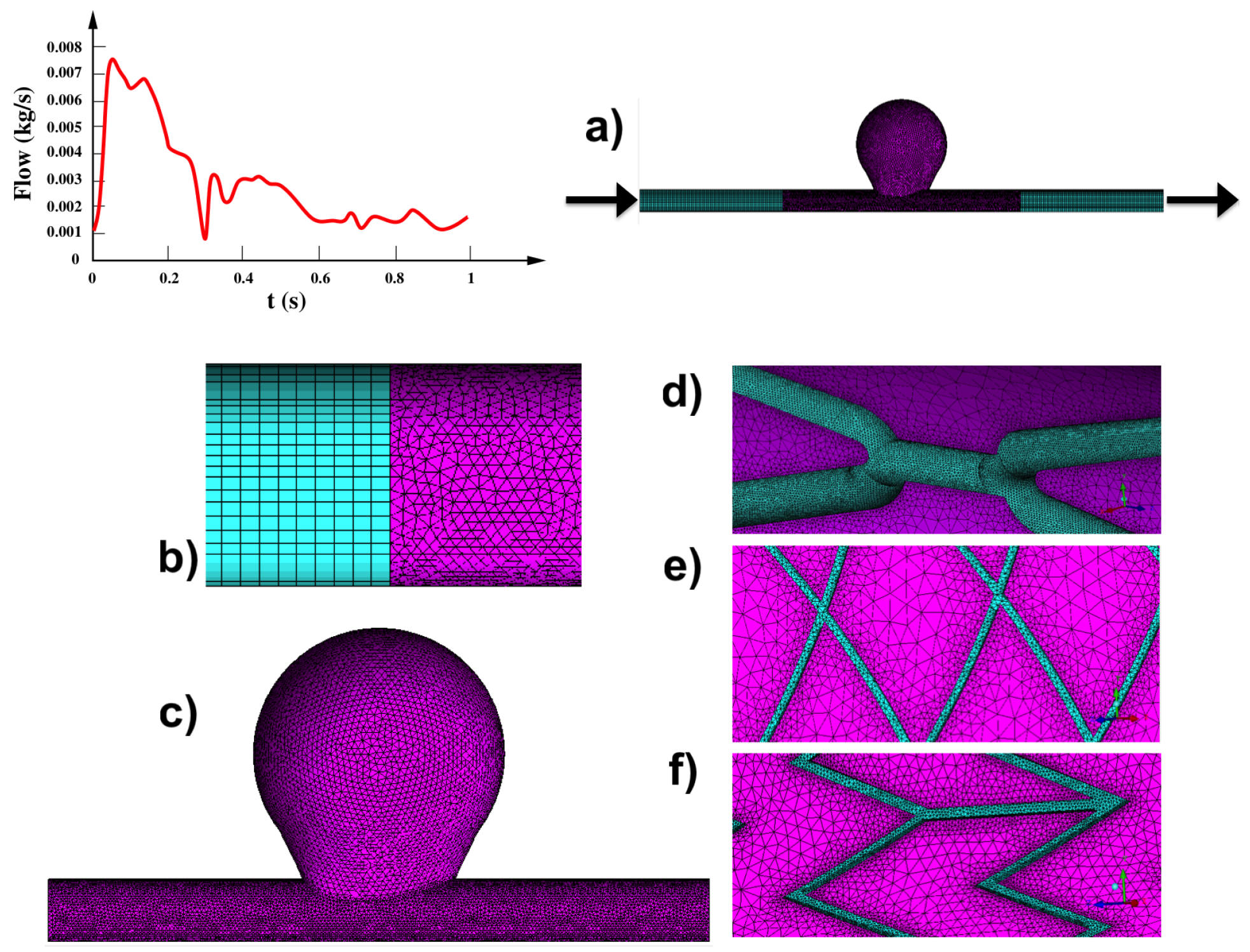
- The boundary condition, i.e., the time-dependent mass flow is adapted from the literature and imposed at the model inlet and outlet.
- Model extensions have been added to the model for guaranteeing that the blood flow in the region of interest (within the artery) is fully developed.
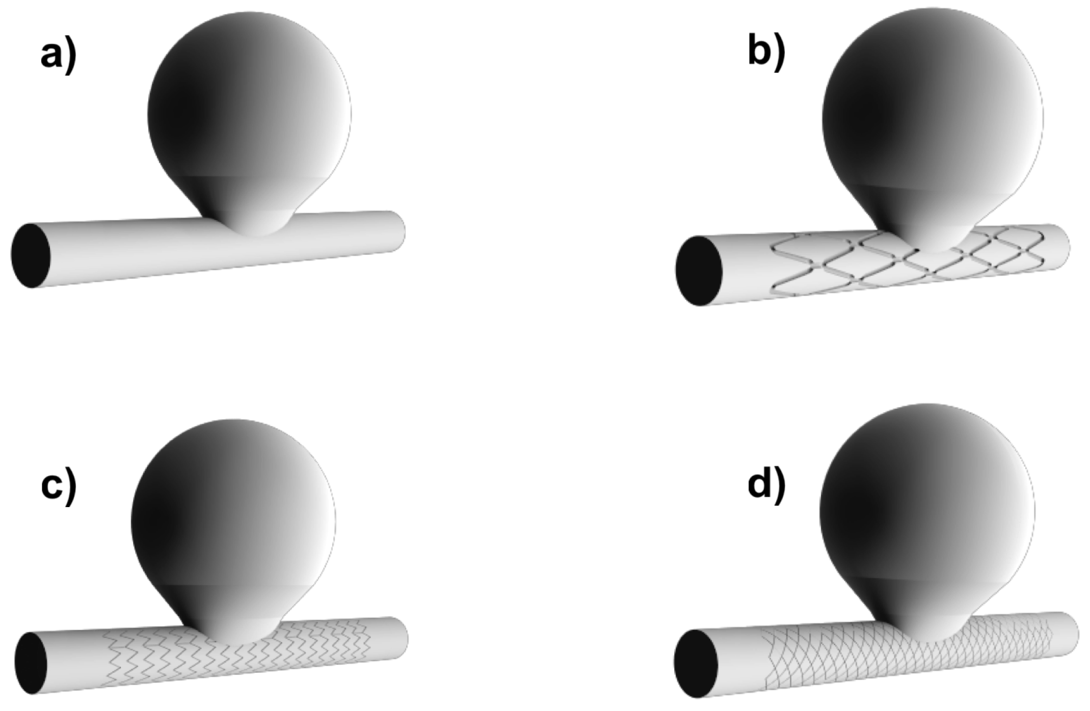
2.2. Geometry: Idealized Aneurysm Model
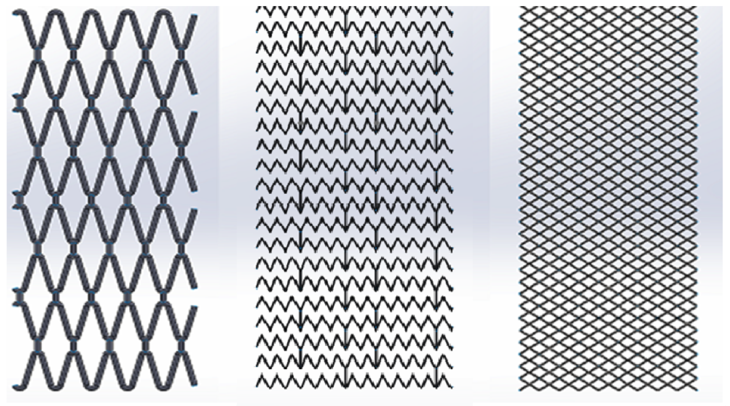
2.3. Flow Diverting Stents
2.4. Numerical Analysis
2.5. Hemodynamics Parameters
3. Results
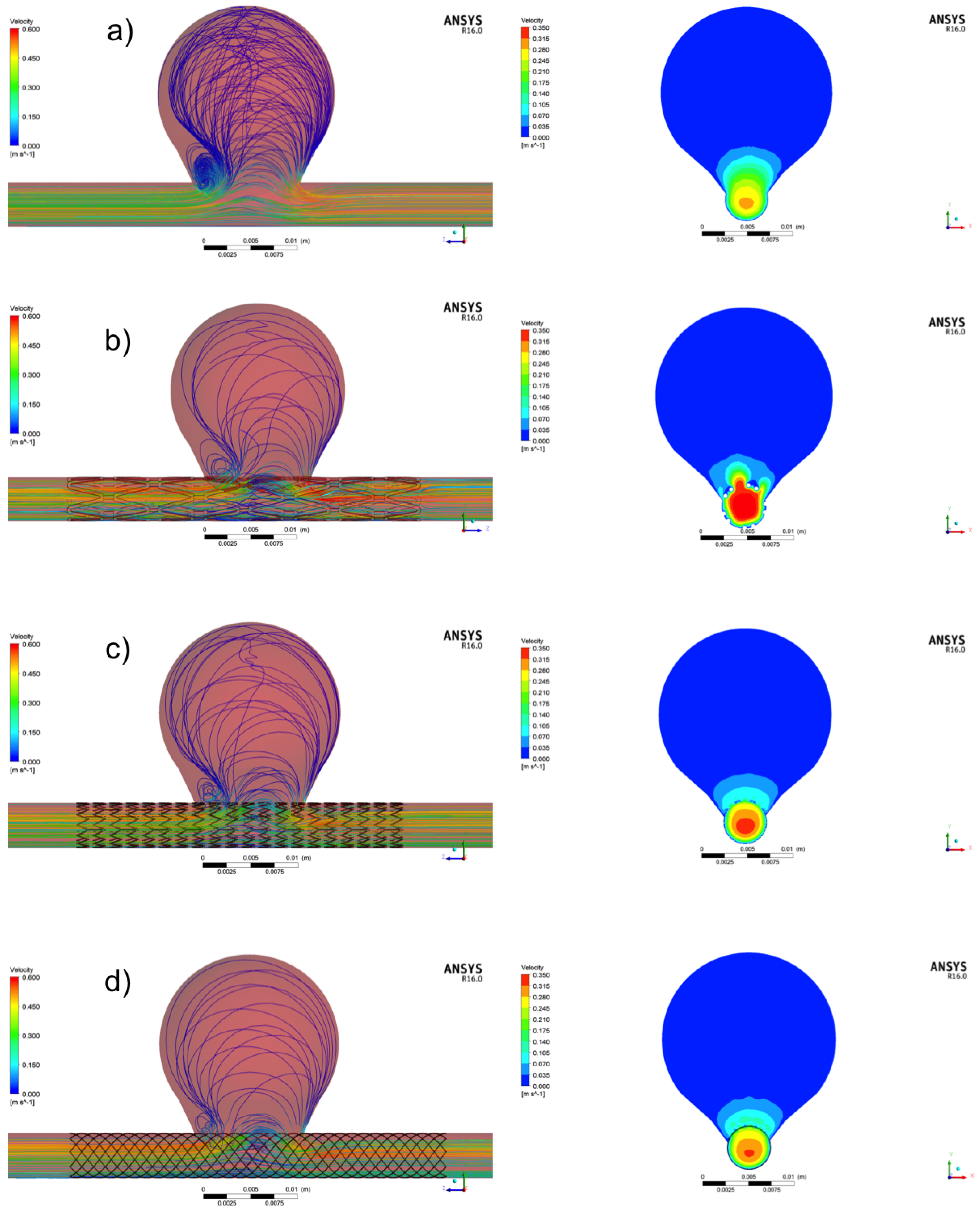
3.1. Aneurysm without Treatment: Control Case
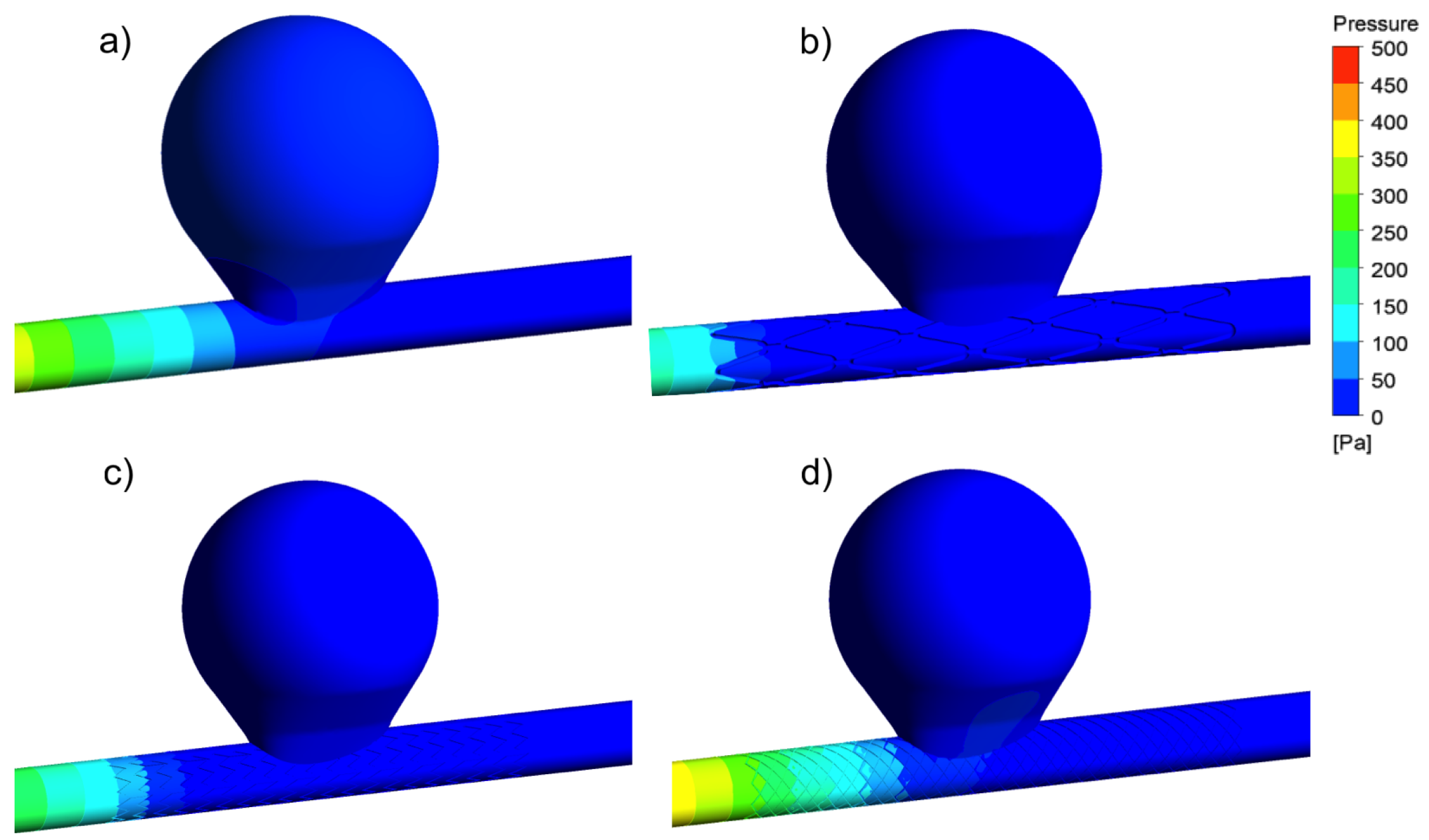
3.2. Aneurysm under FDS Treatment: Flow and Velocity Field
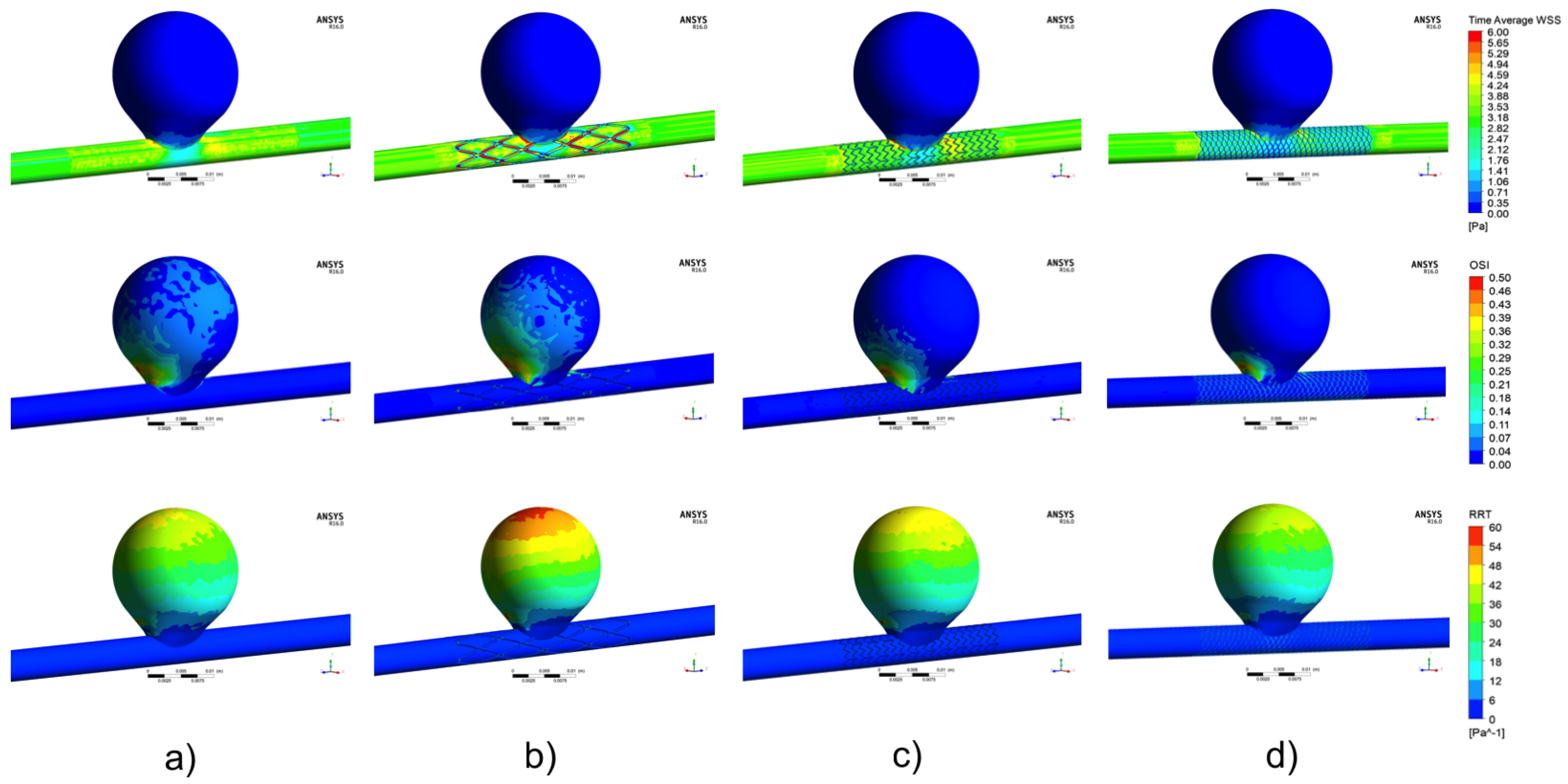
3.3. Aneurysm under FDS Treatment: TAWSS Distribution
3.4. Aneurysm under FDS Treatment: OSI Distribution
3.5. Aneurysm under FDS Treatment: RRT Distribution
4. Discussion
5. Limitations
6. Conclusions
Author Contributions
Funding
Conflicts of Interest
References
- Kim, Y.H.; Xu, X.; Lee, J.S. The effect of stent porosity and strut shape onsaccular aneurysm and its numerical analysis with Lattice Boltzmann method. Ann. Biomed. Eng. 2010, 38, 2274–2292. [Google Scholar] [CrossRef] [PubMed]
- Kulcsár, Z.; Augsburger, L.; Reymond, P.; Pereira, V.M.; Hirsch, S.; Mallik, A.S.; Millar, J.; Wetzel, S.G.; Wanke, I.; Rüfenacht, D.A. Flow diversion treatment: Intra-aneurismal blood flow velocity and WSS reduction are parameters to predict aneurysm thrombosis. Acta Neurochir. Wien 2012, 154, 1827–1834. [Google Scholar] [CrossRef] [PubMed]
- Mut, F.; Raschi, M.; Scrivano, E.; Bleise, C.; Chudyk, J.; Ceratto, R.; Lylyk, P.; Cebral, J.R. Association between hemodynamic conditions and occlusion times after flow diversion in cerebral aneurysms. J. Neurointerv. Surg. 2015, 7, 286–290. [Google Scholar] [CrossRef]
- Ouared, R.; Larrabide, I.; Brina, O.; Bouillot, P.; Erceg, G.; Yilmaz, H.; Lovblad, K.O.; Mendes Pereira, V. Computational fluid dynamics analysis of flow reduction induced by flow-diverting stents in intracranial aneurysms: A patient-unspecific hemodynamics change perspective. J. Neurointerv. Surg. 2016, 8, 1288–1293. [Google Scholar] [CrossRef] [PubMed]
- Lylyk, P.; Miranda, C.; Ceratto, R.; Ferrario, A.; Scrivano, E.; Luna, H.R.; Berez, A.L.; Tran, Q.; Nelson, P.K.; Fiorella, D. Curative endovascular reconstruction of cerebral aneurysms with the pipeline embolization device: the Buenos Aires experience. Neurosurgery 2009, 64, 632–642. [Google Scholar] [CrossRef]
- Becske, T.; Kallmes, D.F.; Saatci, I.; McDougall, C.G.; Szikora, I.; Lanzino, G.; Moran, C.J.; Woo, H.H.; Lopes, D.K.; Berez, A.L.; et al. Pipeline for uncoilable or failed aneurysms: results from a multicenter clinical trial. Radiology 2013, 267, 858–868. [Google Scholar] [CrossRef] [PubMed]
- Kim, M.; Taulbee, D.B.; Tremmel, M.; Meng, H. Comparison of two stents in modifying cerebral aneurysm hemodynamics. Ann. Biomed. Eng. 2008, 36, 726–741. [Google Scholar] [CrossRef]
- Dholakia, R.; Sadasivan, C.; Fiorella, D.J.; Woo, H.H.; Lieber, B.B. Hemodynamics of flow diverters. J. Biomech. Eng. 2017, 139, 021002. [Google Scholar] [CrossRef]
- Lieber, B.B.; Stancampiano, A.P.; Wakhloo, A.K. Alteration of hemodynamics in aneurism models by stenting: Influence on stent porosity. Ann. Biomed. Eng. 1997, 25, 460–469. [Google Scholar] [CrossRef]
- Lieber, B.B.; Livescu, V.; Hopkins, L.N.; Wakhloo, A.K. Particle image velocimetry assessment of stent design influence on intra-aneurysmal flow. Ann. Biomed. Eng. 2002, 30, 768–777. [Google Scholar] [CrossRef] [PubMed]
- Aenis, M.; Stancampiano, A.P.; Wakhloo, A.K.; Lieber, B.B. Modeling of flow in a straight stented and nonstented side wall aneurysm model. J. Biomech. Eng. 1997, 119, 206–212. [Google Scholar] [CrossRef]
- Jou, L.D.; Chintalapani, G.; Mawad, M.E. Metal coverage ratio of pipeline embolization device for treatment of unruptured aneurysms: Reality check. Interv. Neuroradiol. 2016, 22, 42–48. [Google Scholar] [CrossRef] [PubMed]
- Li, Y.; Zhang, M.; Verrelli, D.I.; Chong, W.; Ohta, M.; Quian, Y. Numerical simulation of aneurysmal haemodynamics with calibrated porous-medium models of flow-diverting stents. J. Biomech. 2018, 80, 88–94. [Google Scholar] [CrossRef]
- Zhang, Y.; Wang, Y.; Kao, E.; Flórez-Valencia, L.; Courbebaisse, G. Towards optimal flow diverter porosity for the treatment of intracranial aneurysm. J. Biomech. 2019, 82, 20–27. [Google Scholar] [CrossRef] [PubMed]
- Rhee, K.; Han, M.H.; Cha, S.H. Changes of flow characteristics by stenting in aneurysm models: Influence of aneurysm geometry and stent porosity. Ann. Biomed. Eng. 2002, 30, 894–904. [Google Scholar] [CrossRef]
- Bando, K.; Berger, S.A. Research on fluid-dynamic design criterion of stent used for treatment of aneurysms by means of computational simulation. Comp. Fluid Dyn. J. 2003, 11, 527–531. [Google Scholar]
- Stuhne, G.R.; Steinman, D.A. Finite-element modeling of the hemodynamics of stented aneurysms. J. Biomech. Eng. 1997, 126, 382–387. [Google Scholar] [CrossRef]
- Cebral, J.R.; Lohner, R. Efficient simulation of blood flow past complex endovascular devices using an adaptive embedding technique. IEEE Trans. Med. Imaging 2005, 2005 24, 468–476. [Google Scholar] [CrossRef]
- Larrabide, I.; Aguilar, M.L.; Morales, H.G.; Geers, A.J.; Kulcsár, Z.; Rüfenacht, D.A.; Frangi, A.F. Intra-aneurysmal pressure and flow changes induced by flow diverters: Relation to aneurysm size and shape. AJNR Am. J. Neuroradiol. 2013, 34, 816–822. [Google Scholar] [CrossRef] [PubMed]
- Larrabide, I.; Geers, A.J.; Morales, H.G.; Aguilar, M.L.; Rüfenacht, D.A. Effect of aneurysm and ICA morphology on hemodynamics before and after flow diverter treatment. J. Neurointerv. Surg. 2015, 7, 272–280. [Google Scholar] [CrossRef] [PubMed]
- Larrabide, I.; Geers, A.J.; Morales, H.G.; Bijlenga, P.; Rüfenacht, D.A. Change in aneurysmal flow pulsatility after flow diverter treatment. Comput. Med. Imaging Graph. 2016, 50, 2–8. [Google Scholar] [CrossRef]
- Seshadhri, S.; Janiga, G.; Beuing, O.; Skalej, M.; Thevenin, D. Impact of stents and flow diverters on hemodynamics in idealized aneurysm models. J. Biomech. Eng. 2011, 133, 071005. [Google Scholar] [CrossRef] [PubMed]
- Wu, Y.F.; Yang, P.F.; Shen, J.; Huang, Q.H.; Zhang, X.; Qian, Y.; Liu, J.M. A comparison of the hemodynamic effects of flow diverters on wide-necked and narrow-necked cerebral aneurysms. J. Clin. Neurosci. 2012, 19, 1520–1524. [Google Scholar] [CrossRef] [PubMed]
- Wang, C.; Tian, Z.; Liu, J.; Jing, L.; Paliwal, N.; Wang, S.; Zhang, Y.; Xiang, J.; Siddiqui, A.H.; Meng, H.; et al. Flow diverter effect of LVIS stent on cerebral aneurysm hemodynamics: A comparison with Enterprise stents and the Pipeline device. J. Transl. Med. 2016, 14, 199. [Google Scholar] [CrossRef] [PubMed]
- Mut, F.; Ruijters, D.; Babic, D.; Bleise, C.; Lylyk, P.; Cebral, J.R. Effects of changing physiologic conditions on the in vivo quantification of hemodynamic variables in cerebral aneurysms treated with flow diverting devices. Int. J. Numer. Method Biomed. Eng. 2014, 30, 135–142. [Google Scholar] [CrossRef] [PubMed]
- Cebral, J.R.; Mut, F.; Raschi, M.; Scrivano, E.; Ceratto, R.; Lylyk, P.; Putman, C.M. Aneurysm rupture following treatment with flow-diverting stents: Computational hemodynamics analysis of treatment. AJNR Am. J. Neuroradiol. 2011, 32, 27–33. [Google Scholar] [CrossRef]
- Mut, F.; Cebral, J.R. Effects of flow-diverting device oversizing on hemodynamics alteration in cerebral aneurysms. AJNR Am. J. Neuroradiol. 2012, 33, 2010–2016. [Google Scholar] [CrossRef]
- Zhang, Y.; Chong, W.; Qian, Y. Investigation of intracranial aneurysm hemodynamcs following flow diverter stent treatment. Med. Eng. Phys. 2013, 35, 608–615. [Google Scholar] [CrossRef] [PubMed]
- Levitt, M.R.; McGah, P.M.; Aliseda, A.; Mourad, P.D.; Nerva, J.D.; Vaidya, S.S.; Morton, R.P.; Ghodke, B.V.; Kim, L.J. Cerebral aneurysms treated with flow-diverting stents: Computational models with intravascular blood flow measurements. AJNR Am. J. Neuroradiol. 2014, 35, 143–148. [Google Scholar] [CrossRef]
- Pereira, V.M.; Bonnefous, O.; Ouared, R.; Brina, O.; Stawiaski, J.H.; Aerts, H.; Ruijters, D.; Narata, A.P.; Bijlenga, P.; Schaller, K.; et al. A DSA-based method using contrast-motion estimation for the assessment of the intra-aneurysmal flow changes induced by flow-diverter stents. AJNR Am. J. Neuroradiol. 2013, 34, 808–815. [Google Scholar] [CrossRef]
- Seibert, B.; Tummala, R.P.; Chow, R.; Faridar, A.; Mousavi, S.A.; Divani, A.A. Intracranial aneurysms: Review of current treatment options and outcomes. Front. Neurol. 2011, 2, 1–11. [Google Scholar] [CrossRef]
- Han, X.; Wu, X.; Kelly, M.; Chen, X.B. Fabrication and optimal design of biodegradable polymeric stents for aneurysms treatments. J. Funct. Biomater. 2017, 8, 8. [Google Scholar] [CrossRef]
- Chen, X.B. Extrusion Bioprinting of Scaffolds for Tissue Engineering Applications; Springer International Publishing AG: Cham, Switzerland, 2019. [Google Scholar]
- Waksman, R. Biodegradable stents: They do their job and disappear. J. Invasive Cardiol. 2006, 18, 70–74. [Google Scholar] [PubMed]
- Chen, X.B.; Li, M.; Ke, H. Modeling of the flow rate in the dispensing-based process for fabricating tissue scaffolds. J. Manuf. Sci. Eng. 2008, 130, 021003. [Google Scholar] [CrossRef]
- Li, M.G.; Tian, X.Y.; Chen, X.B. A brief review of dispensing-based rapid prototyping techniques in tissue scaffold fabrication: Role of modeling on scaffold properties prediction. Biofabrication 2009, 1, 032001. [Google Scholar] [CrossRef]
- Johnston, B.M.; Johnston, P.R.; Corney, S.; Kilpatrick, D. Non-Newtonian blood flow in human right coronary arteries: Steady state simulations. J. Biomech. 2004, 37, 709–720. [Google Scholar] [CrossRef]
- Johnston, B.M.; Johnstona, P.R.; Corney, S.; Kilpatrick, D. Non-Newtonian blood flow in human right coronary arteries: Transient simulations. J. Biomech. 2006, 39, 1116–1128. [Google Scholar] [CrossRef] [Green Version]
- Valencia, A.; Villanueva, M. Unsteady flow and mass transfer in models of stenotic arteries considering fluid-structure interaction. Int. Commun. Heat Mass Transf. 2006, 33, 966–975. [Google Scholar] [CrossRef]
- Morlacchi, S.; Chiastra, C.; Gastaldi, D.; Pennati, G.; Dubini, G.; Migliavacca, F. Sequential structural and fluid dynamic numerical simulations of a stented bifurcated coronary artery. J. Biomech. Eng. 2011, 133, 121010. [Google Scholar] [CrossRef]
- Chiastra, C.; Morlacchi, S.; Gallo, D.; Morbiducci, U.; Cárdenes, R.; Larrabide, I.; Migliavacca, F. Computational fluid dynamic simulations of image-based stented coronary bifurcation models. J. R. Soc. Interfaces 2013, 10, 20130193. [Google Scholar] [CrossRef] [PubMed]
- Torii, R.; Oshima, M.; Kobayashi, T.; Takagi, K.; Tezduyar, T.E. Fluid-structure interaction modeling of blood flow and cerebral aneurysm: Significance of artery and aneurysm shapes. Comp. Meth. Appl. Mech. Eng. 2009, 198, 3613–3621. [Google Scholar] [CrossRef]
- LaDisa, J.; Guler, I.; Olson, L. 3D computational fluid dynamics modeling of alterations in coronary wall shear stress produced by stent implantation. Ann. Biomed. Eng. 2003, 31, 972–980. [Google Scholar] [CrossRef]
- LaDisa, J.; Hettrick, D.; Olson, L. Stent impantation alters coronary artery hemodynamics and wall shear stress during maximal vasodilation. J. Appl. Physiol. 2002, 93, 1939–1946. [Google Scholar] [CrossRef]
- LaDisa, J.; Hettrick, D.; Olson, L.; Hettrick, D.; Warltier, D.; Kersten, J.; Pagel, P. Alterations in regional vascular geometry produced by theoretical stent implantation influence distributions of wall shear stress: Analysis of a curved coronary artery using 3D computational fluid dynamics modeling. Biomed. Eng. Online 2006, 5, 40. [Google Scholar] [CrossRef]
- Masson, I.; Boutouyrie, P.; Laurent, S.; Humphrey, J.; Zidi, M. Characterization of arterial wall mechanical behavior and stresses from human clinical. J. Biomech. 2008, 41, 2618–2627. [Google Scholar] [CrossRef]
- Brindise, M.; Chiastra, C.; Burzotta, F.; Migliavacca, F.; Vlachos, P. Hemodynamics of stent implantation procedures in coronary bifurcations: An In Vitro study. Ann. Biomed. Eng. 2017, 45, 542–553. [Google Scholar] [CrossRef]
- Simão, M.; Ferreira, J.M.; Mora-Rodríguez, J.; Fragata, J.; Ramos, H.M. Behaviour of two typical stents towards a new stent evolution. Med. Biol. Eng. Comp. 2017, 55, 1019–1037. [Google Scholar] [CrossRef]
- Simão, M.; Ferreira, J.M.; Mora-Rodríguez, R.H.M. Structural analysis of two different stent configurations. Comp. Meth. Biomech. Biomed. Eng. 2017, 20, 869–883. [Google Scholar] [CrossRef]
- Xiang, J.; Natarajan, S.K.; Tremmel, M.; Ma, D.; Mocco, J.; Hopkins, L.N.; Siddiqui, A.H.; Levy, E.I.; Meng, H. Hemodynamic-morphologic discriminants for intracranial aneurysm rupture. Stroke 2011, 42, 144–152. [Google Scholar] [CrossRef]
- Kawaguchi, T.; Nishimura, S.; Kanamori, M.; Takazawa, H.; Omodaka, S.; Sato, K.; Maeda, N.; Yokoyama, Y.; Midorikawa, H.; Sasaki, T.; et al. Distinctive flow pattern of wall shear stress and oscillatory shear index: Similarity and dissimilarity in ruptured and unruptured cerebral aneurysm blebs. J. Neurosurg. 2012, 117, 774–780. [Google Scholar] [CrossRef]
- Lv, N.; Wang, C.; Karmonik, C.; Fang, Y.; Xu, J.; Yu, Y.; Cao, W.; Liu, J.; Huang, Q. Morphological and hemodynamic discriminators for rupture status in posterior communicating artery aneurysms. PLoS ONE 2016, 11, e0149906. [Google Scholar] [CrossRef]
- Bernardini, A.; Larrabide, I.; Morales, H.G.; Pennati, G.; Petrini, L.; Cito, S.; Frangi, A.F. Influence of different computational approaches for stent deployment on cerebral aneurysm haemodynamics. Interface Focus 2011, 1, 338–348. [Google Scholar] [CrossRef] [Green Version]
- He, X.; Ku, D.N. Pulsatile flow in the human left coronary artery bifurcation: Average conditions. J. Biomech. Eng. 1996, 118, 74–82. [Google Scholar] [CrossRef]
- Himburg, H.A.; Grzybowski, D.M.; Hazel, A.L.; LaMack, J.A.; Li, X.M.; Friedman, M.H. Spatial comparison between wall shear stress measures and porcine arterial endothelial permeability. Am. J. Physiol. Heart Circ. Physiol. 2004, 286, H1916–H1922. [Google Scholar] [CrossRef] [Green Version]
- Jou, L.D.; Lee, D.H.; Morsi, H.; Mawad, M.E. Wall shear stress on ruptured and unruptured intracranial aneurysms at the internal carotid artery. AJNR Am. J. Neuroradiol. 2008, 29, 1761–1767. [Google Scholar] [CrossRef]
- Meng, H.; Wang, Z.; Kim, M.; Ecker, R.D.; Hopkins, L.N. Saccular aneurysms on straight and curved vessels are subject to different hemodynamics: Implications of intravascular stenting. AJNR Am. J. Neuroradiol. 2006, 27, 1861–1865. [Google Scholar]
- Ohta, M.; Hirabayashi, M.; Wetzel, S.; Lylyk, P.; Wata, H.; Tsutsumi, S.; Rüfenacht, D.A. Impact of stent design on intra-aneurysmal flow. A computer simulation study. Interv. Neuroradiol. 2004, 10, 85–94. [Google Scholar] [CrossRef]
- Anzai, H.; Falcone, J.L.; Chopard, B.; Hayase, T.; Ohta, M. Optimization of strut placement in flow diverter stents for four different aneurysm configurations. J. Biomech. Eng. 2004, 136, 061006. [Google Scholar] [CrossRef]
- Malek, A.M.; Alper, S.L.; Izumo, S. Hemodynamic shear stress and its role in atherosclerosis. JAMA 1999, 282, 2035–2042. [Google Scholar] [CrossRef] [PubMed]
- Hayashi, K.; Handa, H.; Nagasawa, S.; Okamura, A.; Moritake, K. Stiffness and elastic behavior of human intracranial and extracranial arteries. J. Biomech. 1980, 13, 175–184. [Google Scholar] [CrossRef]


| Thickness (mm) | Length (mm) | Diameter (mm) | |
|---|---|---|---|
| STENT BS | 0.4 | 40 | 4.75 |
| STENT 1 | 0.1 | 40 | 4.75 |
| STENT 2 | 0.1 | 40 | 4.75 |
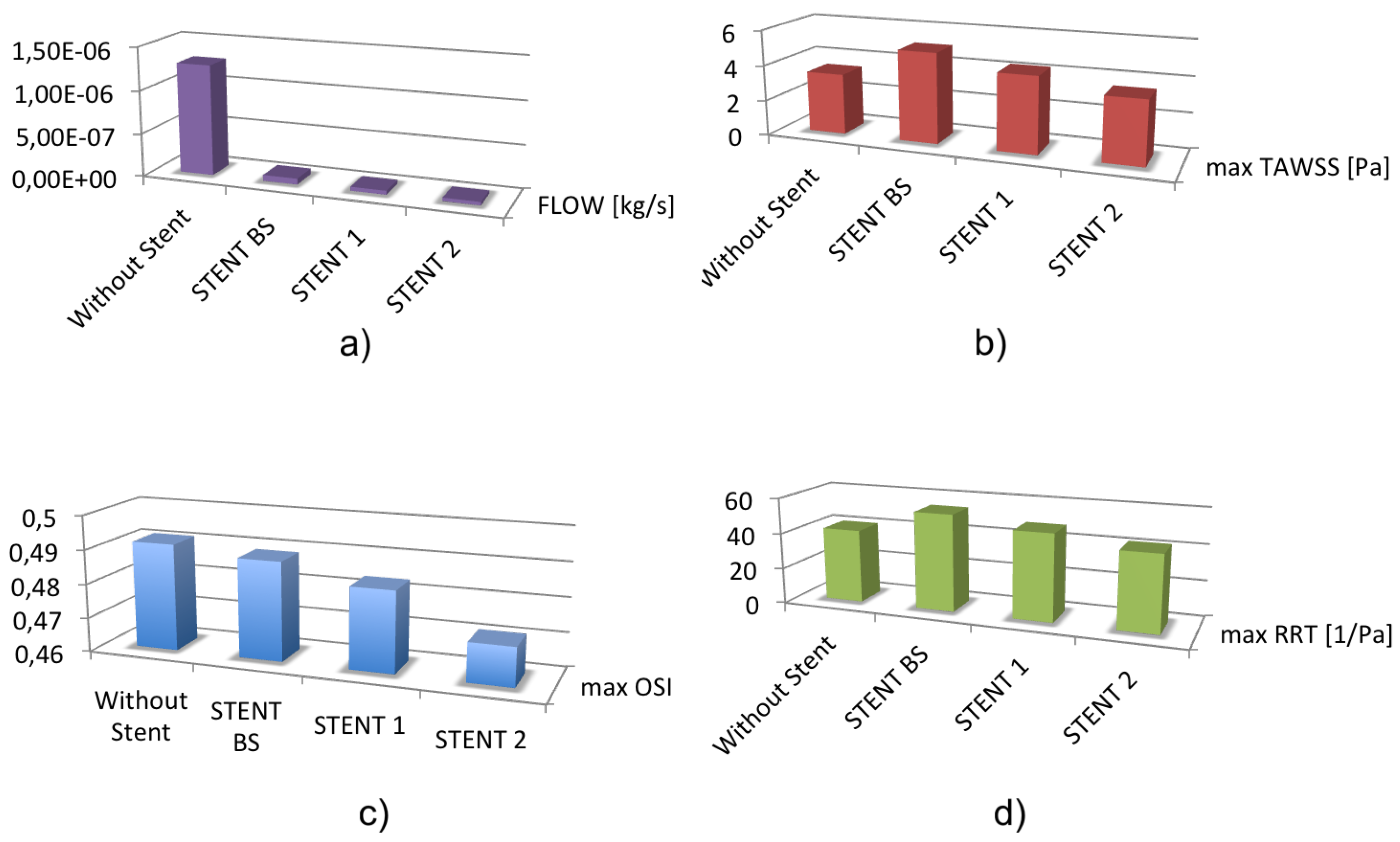
| Flow (Kg/s) (mm) | Max TAWSS (mm) | Max OSI (mm) | Max RRT (mm) | |
|---|---|---|---|---|
| Control case | 3.43 | 0.49 | 41.09 | |
| STENT BS | 5.09 | 0.48 | 54.25 | |
| STENT 1 | 4.29 | 0.48 | 48.42 | |
| STENT 2 | 3.56 | 0.47 | 42.42 |
© 2019 by the authors. Licensee MDPI, Basel, Switzerland. This article is an open access article distributed under the terms and conditions of the Creative Commons Attribution (CC BY) license (http://creativecommons.org/licenses/by/4.0/).
Share and Cite
Catalán-Echeverría, B.; Kelly, M.E.; Peeling, L.; Bergstrom, D.; Chen, X.; Malvè, M. CFD-Based Comparison Study of a New Flow Diverting Stent and Commercially-Available Ones for the Treatment of Cerebral Aneurysms. Appl. Sci. 2019, 9, 1341. https://doi.org/10.3390/app9071341
Catalán-Echeverría B, Kelly ME, Peeling L, Bergstrom D, Chen X, Malvè M. CFD-Based Comparison Study of a New Flow Diverting Stent and Commercially-Available Ones for the Treatment of Cerebral Aneurysms. Applied Sciences. 2019; 9(7):1341. https://doi.org/10.3390/app9071341
Chicago/Turabian StyleCatalán-Echeverría, Borja, Michael E. Kelly, Lissa Peeling, Donald Bergstrom, Xiongbiao Chen, and Mauro Malvè. 2019. "CFD-Based Comparison Study of a New Flow Diverting Stent and Commercially-Available Ones for the Treatment of Cerebral Aneurysms" Applied Sciences 9, no. 7: 1341. https://doi.org/10.3390/app9071341