
A Novel Augmented Reality Mobile-Based Application for Biomechanical Measurement


1
Ottawa Hospital Research Institute, Ottawa, ON K1H 8L6, Canada
2
Department of Mechanical Engineering, University of Ottawa, Ottawa, ON K1N 6N5, Canada
*
Author to whom correspondence should be addressed.
BioMed 2022, 2(2), 255-269; https://doi.org/10.3390/biomed2020021
Submission received: 7 March 2022
/
Revised: 20 May 2022
/
Accepted: 26 May 2022
/
Published: 28 May 2022
Abstract
:Human posture and range of motion (ROM) measurements are important health indicators for identifying abnormalities from various disorders (e.g., scoliosis, musculoskeletal disorders, pain syndromes). A viable real-time mobile application for measuring body posture and ROM is currently lacking. To address this need, a novel Android smartphone augmented-reality-based application was developed and evaluated to enable real-time AprilTag2 marker measurement at the point of patient contact (Biomechanical Augmented Reality-Marker, BAR-M). Mobile app performance was evaluated on a body opponent bag (BOB) and 15 healthy participants by comparing smartphone app and Vicon motion analysis output (pelvis, shoulder, arm, torso angles). A Samsung Galaxy smartphone recorded live video, calculated AprilTag orientations and angle of “a line connecting the center of two tags”, and displayed outcomes in real time. For the BOB test, the absolute difference between Vicon and smartphone angles were 0.09° ± 0.05° for hip, 0.09° ± 0.06° for shoulder, and 0.69° for arm abduction. For the participant test, the absolute mean angle differences were 1.70° ± 0.23° for hip, 1.34° ± 0.27° for shoulder, and 11.18° ± 3.68° for arm abduction. Overall, the app obtained valid and reliable angle measurements for postural and ROM assessments using the smartphone’s front camera. Arm abduction results were affected by clothing movement that caused Vicon markers to move differently from AprilTag markers. Thus, with appropriate measurement methods, this real-time smartphone app is a viable tool to facilitate immediate clinical decision making based on human posture and ROM assessments.
1. Introduction
Posture is the body’s position or bearing for a special purpose, and can be related to health [1]. When considering movement, joint range of motion (ROM) is often used in clinical assessments. Currently, several methods can be used to quantify human posture and ROM measurements in clinical practice. A conventional approach is to make measurements manually, with a goniometer, tape, etc. However, visual observation can be affected by human error [2], which can lead to improper clinical decisions and thereby long-term issues for the patient (e.g., improper pelvis alignment leading to back problems for prosthesis users).
To mitigate human error, advanced technologies can be used to assist with accurate quantification of human body postural measurement. Technology-based methods include inertial measurement unit (IMU) sensors, marker-based systems, and markerless motion analysis systems.
Marker-based systems capture the movement of markers placed on the person. Systems use active, magnetic, or passive markers. Passive marker systems typically use retro-reflective balls that are illuminated using infrared (IR) lights mounted on the cameras such as Vicon (Oxford, England). While Vicon systems are accurate, using them in clinical practice is limited due to motion lab space requirements, prohibitive system cost, and the time required for patient setup and data processing [3,4]. Despite the high accuracy, passive markers present challenges in postprocessing 3D data for markers close to each other [5], often requiring manual editing to relabel markers [6,7]. Reflective surfaces in the background may also be mistaken for body markers, requiring manual background masking or relabeling [8].
Active marker systems use light-emitting diodes (LED) as markers, with each marker having a predefined frequency to assist in marker differentiation [9]. However, individuals need to carry several cables and other components that may affect their movements. Active markers systems include Codamotion (Rothley, England), Optotrak (Northern Digital, Inc., Waterloo, Ontario, Canada), Qualysis (Göteborg, Sweden), and Selcon (Selspot Systems, Ltd., Southfield, Michigan) [10]. Active markers can eliminate errors due to marker misidentification and therefore reduce marker sorting time during postprocessing [11].
In magnetic systems, low-frequency quasi-static magnetic fields can be used to determine position and orientation of a sensor relative to a source [12]. While these 3D measurement systems are portable, they are more cumbersome to employ due to the system’s power, size, and weight [12] and are susceptible to metal within the capture volume.
Markerless systems could be used in movement analysis to reduce participant preparation time and encourage natural movement, since tracking markers are not required. Posture can be qualitatively and quantitatively assessed by interpreting photographs. For example, recent developments in pose estimation algorithms, particularly in the field of artificial intelligence, have improved posture prediction from videos by converting video frames into body component coordinates. Numerous algorithms for estimating poses have been presented [13,14,15]. However, based on human posture estimate performance, deep learning algorithms were shown to be the most powerful [16]. Pose estimation algorithms have potential for measuring human movement; however, accurate human pose quantification requires a substantial amount of data for training and specific landmarks not included in the pose estimation model cannot be identified. Therefore, a marker-based approach could be more beneficial in many instances.
Another example of markerless systems is obtaining body angle measurements by manually post processing each frame recorded on the video. Angle measurements on stored video have been implemented as mobile phone apps or web-based applications [17,18] by selecting three points on the video frame (i.e., online goniometer). While angle measurement is accurate based on the selected points, points on the video might not be the exact anatomical positions. Additional drawbacks include the time required for capturing video, processing markers, and reporting results. However, this approach allows clinicians to step through the stored video frames, which can aid observational movement analysis.
Current motion analysis lab methods can have high purchase and installation costs, time-consuming data collection and analysis, and require a permanent, large footprint. Therefore, there is a need for a reliable, affordable, and easily accessible system to quantify posture measurement, body segment positioning, and symmetry at the point of patient contact. As a result, recent studies have developed mobile phone applications to provide an affordable solution for human angle measurement.
Biomechanics Augmented Reality (BAR) is an example of an AR-based smartphone app for real-time human angle measurement and result reporting [19]. BAR measures angles using the phone’s orientation to gravity via the smartphone sensors and displays results over live video in real time. The app can also show a grid overlay as a visualization aid. Real-time angle measurements on a smartphone facilitate immediate clinical decision making; however, BAR cannot measure ROM and specific body landmarks.
OpenPose-based markerless keypoint identification has also been implemented on a smartphone to measure ankle, knee, and hip flexion/extension angles by analyzing images taken from the recorded video using the smart phone’s camera. The OpenPose 2D real-time multi-person keypoint detection technology matches linked parts of the human body with people in the video using Convolutional Neural Networks (CNNs) [20]. However, the smartphone application has not been validated using a gold standard system such as Vicon. OpenPose was shown to provide better results than BlazePose (smartphone enabled model for Google ML Kit) for typical movements used in clinical analysis [21]. While these smartphone tools could be used anywhere, analyzing human anatomical points beyond the available model is not feasible.
Considering the drawbacks of these methods, we propose a prototype, novel AR-based smartphone application using fiducial markers (AprilTag2) [22,23] to enable mobile human posture, body symmetry, and angle measurement in real-time with inexpensive and accurate computational processes. Fiducial marker systems are defined objects in an optical imaging device’s field of view and can be dynamically detected in software. These markers are best applied when a relative pose between a source and object is needed; for example, robotics, AR, or human–computer interaction. Ideally, a clinician will be able to hold markers on a patient’s anatomical locations and see the outcome measurement immediately on the mobile device.
In this research, we developed and evaluated the Biomechanics Augmented Reality Marker (BAR-M) smartphone app to fill the gap between cost, accessibility, and system accuracy for functionality in clinical situations, specifically human posture, body symmetry, and ROM measurement. After successful evaluation of this smartphone app in clinical situations, this AR-based digital measurement tool could be used by clinicians to obtain real-time angle measurements to assist in clinical decision making at the point of patient contact.
2. BAR-M System Development
The BAR-M system consists of three main components to be used in clinical practice including: 1- AprilTag fiducial marker; 2- Mobile application; and 3- BAR-M adapter.
2.1. AprilTag
AprilTag2 was used as BAR-M application markers. AprilTag2 improved on the original AprilTag by providing greater reliability than other fiducial systems, with better detection performance, fewer false positives, and shorter computational time [22,23]. The lexicode-based generation process reduced false positive rates without hindering location accuracy [22,24]. AprilTag works robustly in lens distortion, occlusion, and warping [25], but with increased sensitivity to edge occlusions, limiting its effectiveness for cases where occlusion occurs [26]. Upon occlusion of the internal portion of the tags, AprilTag markers performed at satisfactory levels, yielding a detection rate of 50–100% depending on the tag ID [26]. AprilTag showed strong resistance to lateral and normal rotations since markers were detected and recognized at 0°, 10°, 20°, 30°, 45°, 55°, and 65° relative to both rotation directions (clockwise and counterclockwise) [26]. Another study assessed AprilTag2 performance on a smartphone [27]. The results supported robust tag detection on smartphones and other computation-constrained devices, substantially enhancing their application for real-time tag tracking. Markers were identified and recognized at 0°, 5°, 10°, 15°, 20°, and 25° relative to both clockwise and counterclockwise rotations. Moreover, these markers demonstrated resistance to camera yaw and tilt rotations. Thus, even though the tags are not completely parallel and the mobile device screen is not vertical to gravity, AprilTag2 reliability on smartphones was supported [27].
2.2. BAR-M Application Design
The novel BAR-M Android app tracks AprilTag2 orientation and 2D position in real time. The core AprilTag2 image processing library (C language) was not modified and Java language was used for the AprilTag2 library with the Java Native Interface (JNI).
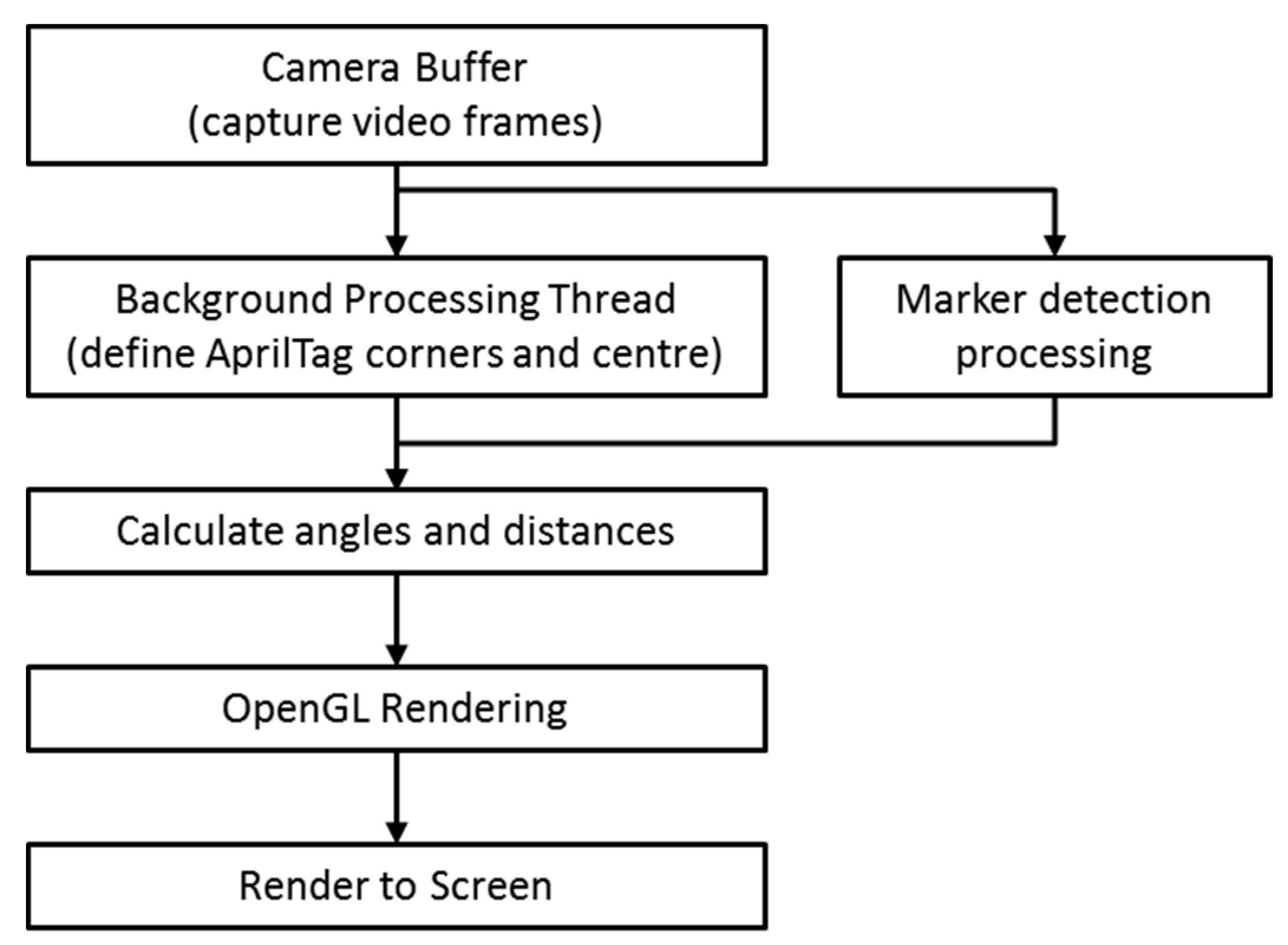
A background thread receives frames captured by the smart phone camera (Figure 1). To use the AprilTag2 library, this thread parses frame data and delivers the data to the JNI. Through the JNI, the AprilTag library returns (x,y) coordinates for marker corners and tag centers. This is done using regional slope equations and a scale factor (a ratio between marker real-world dimensions and marker coordinates in pixels) [28].
Overlayed visuals are rendered by OpenGL in the correct perspective relative to the smartphone and marker along with marker coordinates transformed into a global affine coordinate frame (Figure 1).
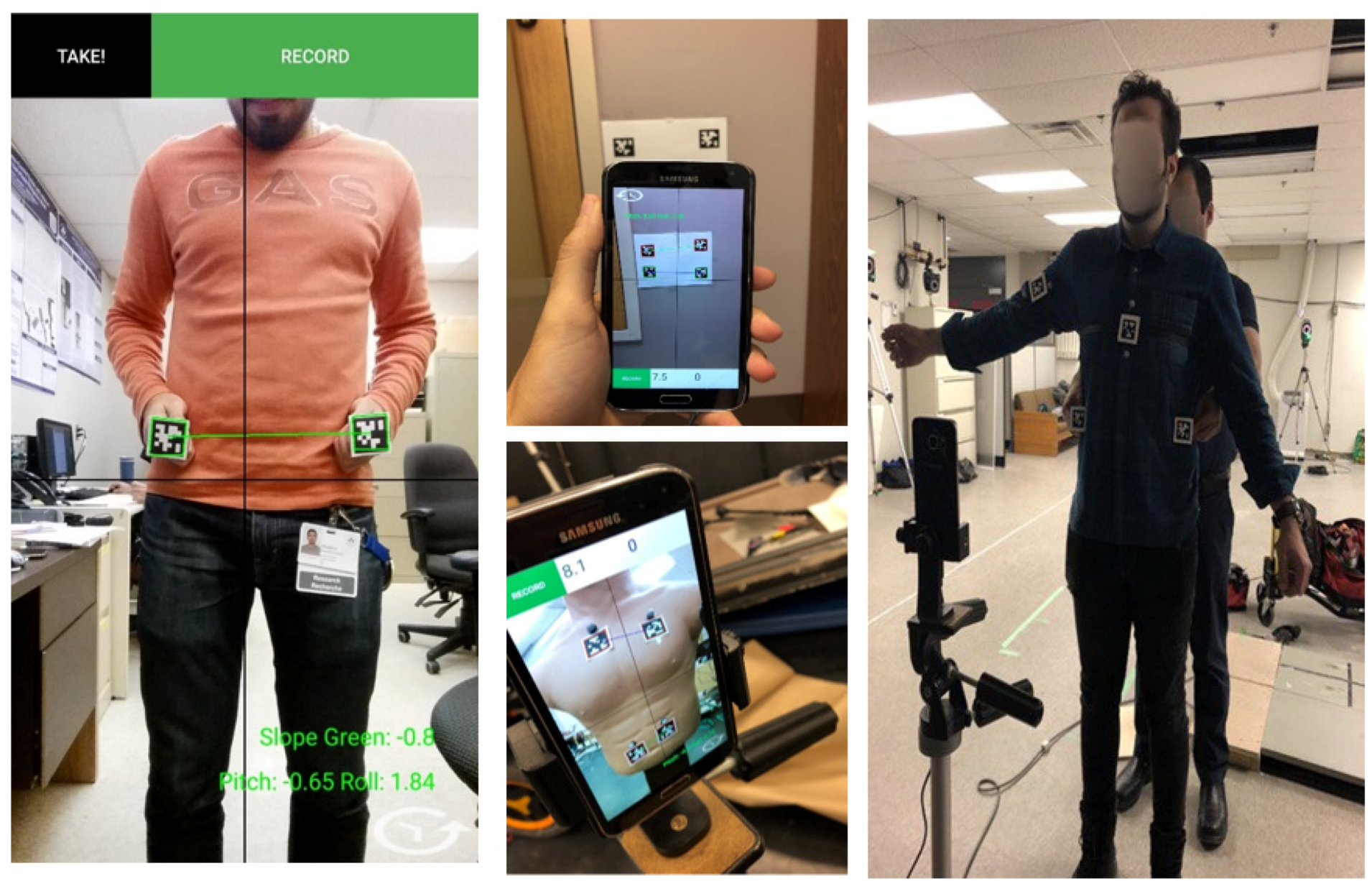
In addition to displaying a box around each marker, the graphical overlay draws a line connecting marker centers. The app stores frame timings, marker corner coordinates, marker center coordinates, and marker side lengths in a .csv file (units in pixels). The user can choose between two live AR views: individual marker angle to horizontal (determined by camera sensor gravity vector) or angle between a line connecting the centers of two markers and horizontal (Figure 2).
2.3. BAR-M Adapter Design
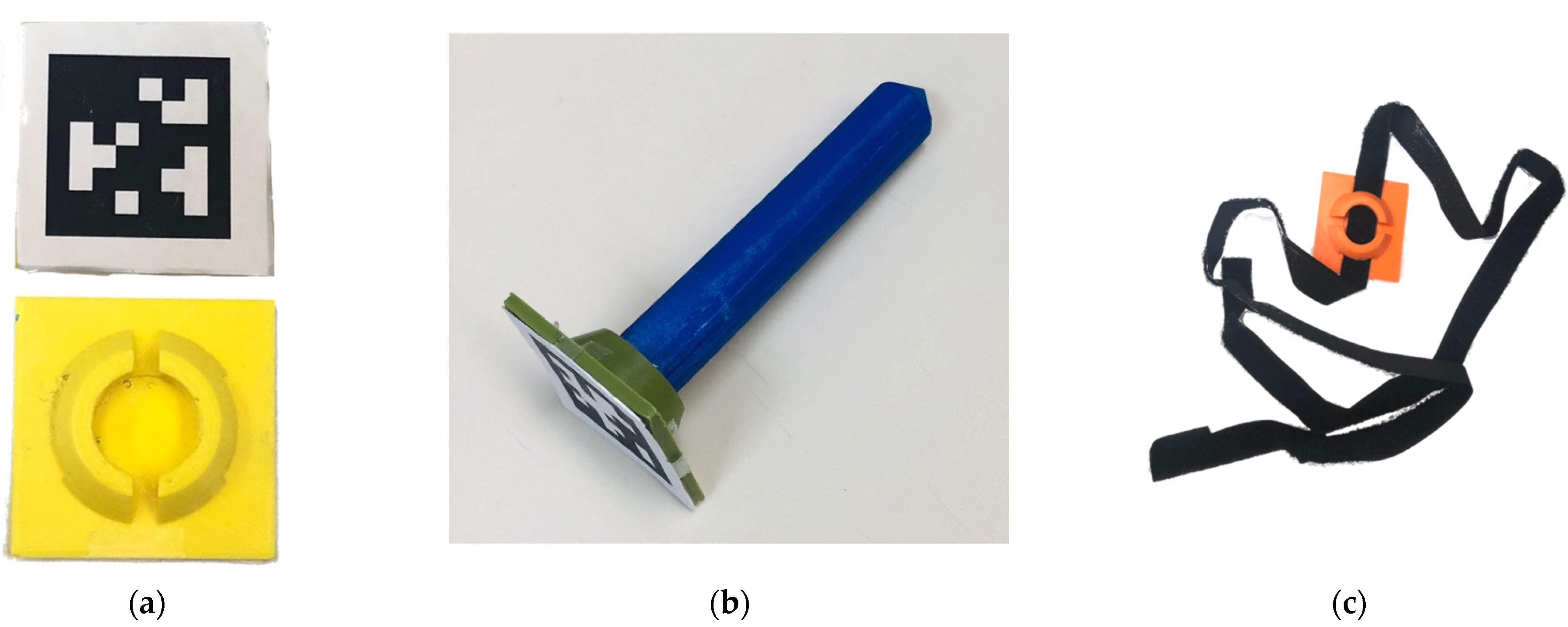
AprilTag2 markers were mounted on custom 3D-printed adapters to enable positioning at anatomical locations (Figure 3 and Figure 4):
- Flat mount: Square mount with AprilTag on one side and various mounting options on the other side (post-adapter, Velcro, caliper). The plastic mount can be held in square or diamond orientations, with the diamond approach enabling point contact between the mount and the anatomical location.
- Post adapter: Orients the AprilTag normal to a pointed post. The post can be placed on an anatomical landmark, especially for landmarks like the superior iliac spine that can be obscured from the camera.
- Velcro adapter: A Velcro band can pass through the flat mount, to secure the mount to the body or limb (i.e., upper arm, chest, etc.).
3. Methods
This study was designed to assess BAR-M app accuracy compared with a Vicon motion capture system (Vicon MX40; 4 megapixels; Vicon Motion Systems Ltd., Oxford, UK). Vicon was used as a gold standard because of its high accuracy and precision. Distances between markers have been used to evaluate both precision (0.015 mm) and accuracy (0.15 mm) of motion caption systems [7,29].
To evaluate BAR-M functionality for clinical situations, pelvis obliquity, shoulder position, and arm-abduction measurements were obtained for a body opponent bag (BOB) and human.
3.1. Body Opponent Bag
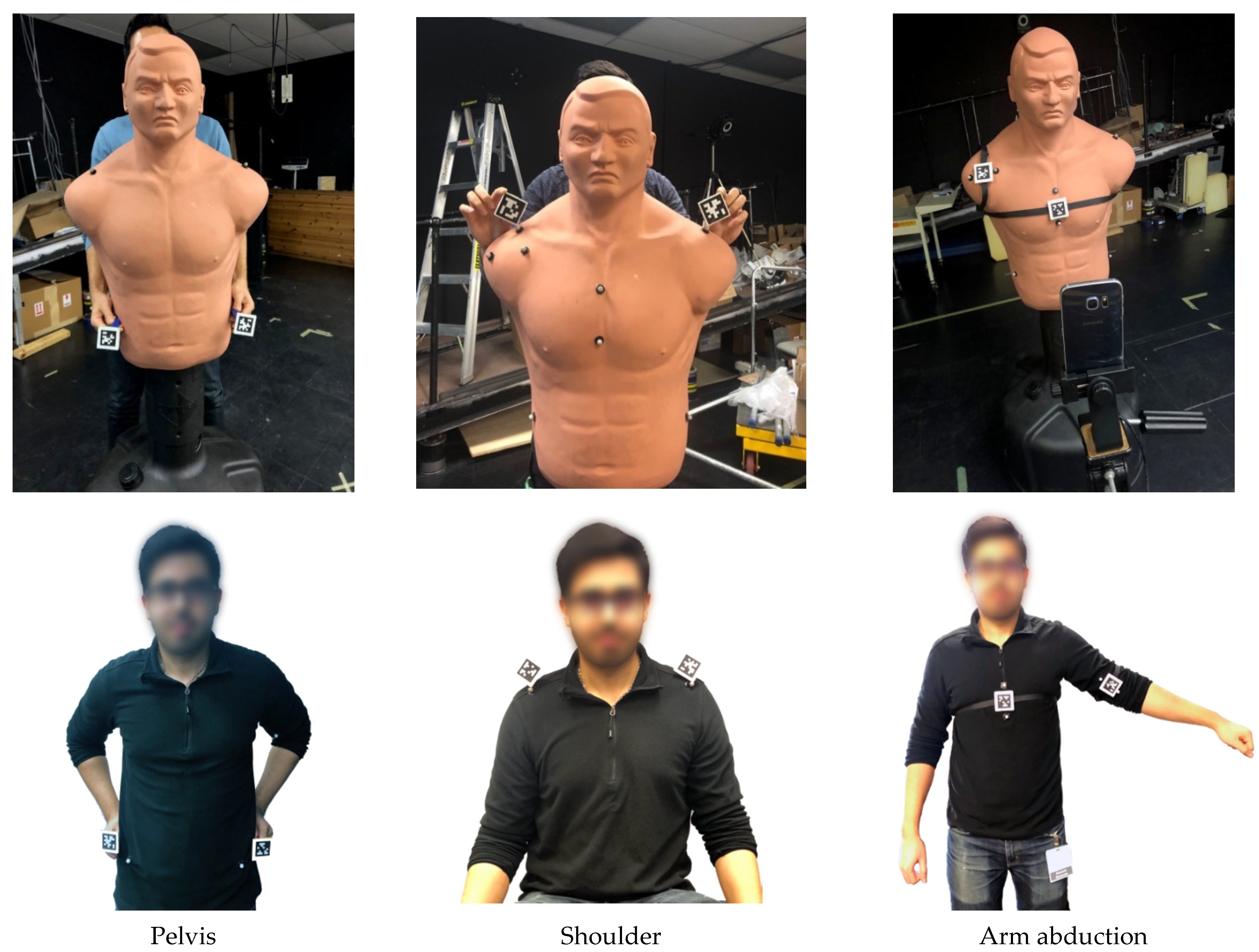
A BOB mannequin was the static human surrogate for initial evaluation, since anatomical-based measurements could be made without human movement and tissue variability. Reflective markers were attached to the BOB pelvis (superior iliac spines), shoulder (acromioclavicular joint), arm, and torso (zyphoid process) to enable 3D marker tracking with a 10-camera Vicon motion analysis system (Figure 4). Angles between the reflective markers were calculated as a gold standard comparator.
For BAR-M, a Samsung S6 smartphone was set up on a tripod such that the screen was 1m in front and parallel to the BOB frontal plane. The application tracked AprilTag2 coordinates, calculated the angle formed by the tag centers, and displayed the angle onscreen in real time (i.e., angle between a line connecting two tags and the phone orientation to gravity, reported as an angle from the horizontal), and stored tag coordinates, angles, and time for further analysis.
Vicon and app data were collected simultaneously for all trials. The app and Vicon system were synchronized by auditory start cue. Vicon marker data were collected at 100 Hz. The BAR-M data collection rate was approximately 19 Hz, varying from 18 to 21 Hz dependent on settings. One second of steady-state data (i.e., lowest standard deviation) was averaged for each comparative measure.
AprilTag markers were co-located beside reflective markers. Two post adapters were used for pelvic obliquity measurements (Figure 4). Flat mounts were held in a diamond position (i.e., corner vertical) for shoulder angle measurement. Velcro adapter markers were secured to the upper arm and torso for arm abduction angle measurement (i.e., angle between torso and arm).
All measurements were made by the same person, who stood behind the BOB and held adapters next to the reflective markers. Since BOB arm abduction was constant with the Velcro attachment, 1 trial was recorded. Pelvis and shoulder angles were measured 10 times since BAR-M markers were hand held. Hand holding markers replicates a clinical use scenario where the clinician holds the markers on the patient’s body and then reads the measurement from the screen.
3.2. Human Testing
A convenience sample of 15 healthy adults were recruited (14 male, 1 female). All measurements were made by one evaluator. All participants provided informed consent and signed a consent form (uOttawa Research Ethics Board approved). Exclusion criteria were balance problems that affect safe standing and cognitive problems that made following instructions difficult.
An eight-marker set was affixed to each participant: acromia, anterior superior iliac crests, superior iliac crests, torso, and arms. The participant was positioned 1 m in front of the phone, such that the body frontal plane was parallel to the phone screen.
For pelvis obliquity, the participant stood still with their right leg on a 2 mm thick plate, simulating hip misalignment, with arms at their sides. The evaluator stood behind the participant and held post adapters on the left and right posterior superior iliac crests for at least 3 s (Figure 4). In addition to the same saved data as the BOB test, the person making the measurement recorded the most consistent angle from the app’s real-time display (i.e., angle that a clinician would select in practice). This procedure was repeated 10 times. Angles from the anterior superior iliac crests’ reflective markers were used as comparators.
For shoulder angle, the participant stood with arms at their sides. The evaluator stood behind the participant and held two marker adaptors in a diamond orientation on top of the reflective markers on the acromioclavicular joints for at least 3 s (Figure 4). Saved data and evaluator recorded angle were logged. This procedure was repeated 10 times.
For arm abduction angle, the participant stood with arms at their sides and facing the camera. Velcro straps secured AprilTags to the participant. The evaluator positioned the torso AprilTag vertically at the center of the participant’s front. Two reflective markers were positioned on the chest above and below the adaptor. The upper arm adaptor was aligned to the arm’s long axis and two reflective markers were positioned beside the adaptor, along this axis. The participant abducted their arm to their comfortable range and held the position for 3 s (Figure 4). Angles of each AprilTag orientation with respect to the horizontal were displayed on the app screen and saved on the phone.
4. Results
For the BOB test, the absolute mean difference between Vicon and app results were 0.09° ± 0.05° for pelvis angle (range 0.02° to 0.2°, p = 0.70), 0.09° ± 0.06° for shoulder angle (range 0° to 0.18°, p = 0.51), and 0.69° for arm abduction.
For the participant test, the absolute mean difference between Vicon and app angle was 1.70° ± 0.23° for pelvis (range 0.59° to 3.37°, p < 0.001), 1.34° ± 0.27° for shoulder angle (range 0.35° to 3.70°, p < 0.001), and 11.18° ± 3.68° for arm abduction (range 1.93° to 28.46°, p = 0.71). After removing outliers, the new absolute mean difference for arm abduction was reduced to 7.68° ± 3.62° and a maximum difference of 11.60°.
The absolute mean difference between the value read from the app AR display and data stored on the phone was 0.19° ± 0.09° for pelvis measurement (range 0.10° to 0.29°, p < 0.001) and 0.12° ± 0.09° for shoulder angle (range 0.03° to 0.23°, p = 0.83). Detailed participant test results are given in Table 1.
Arm Abduction
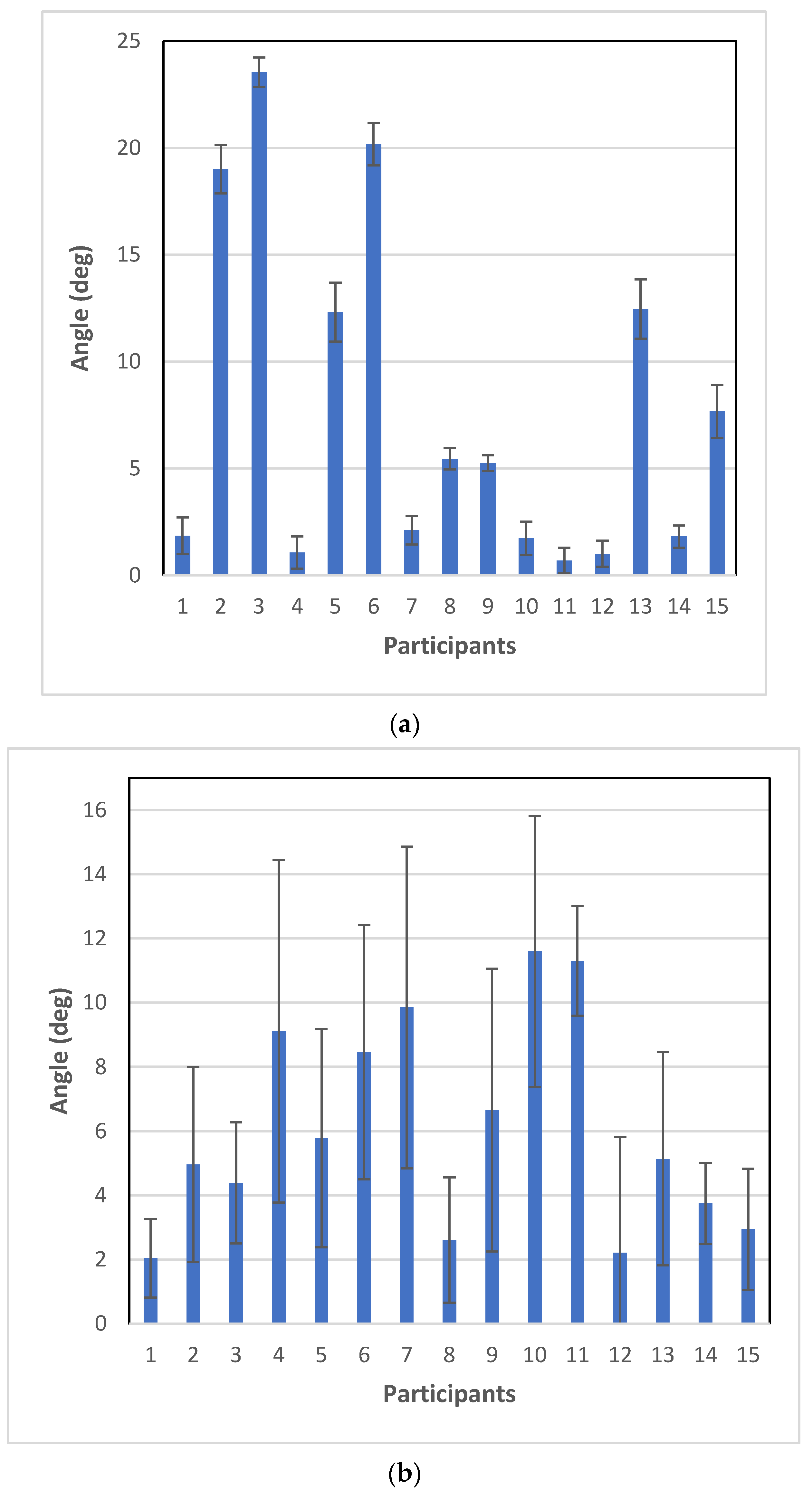
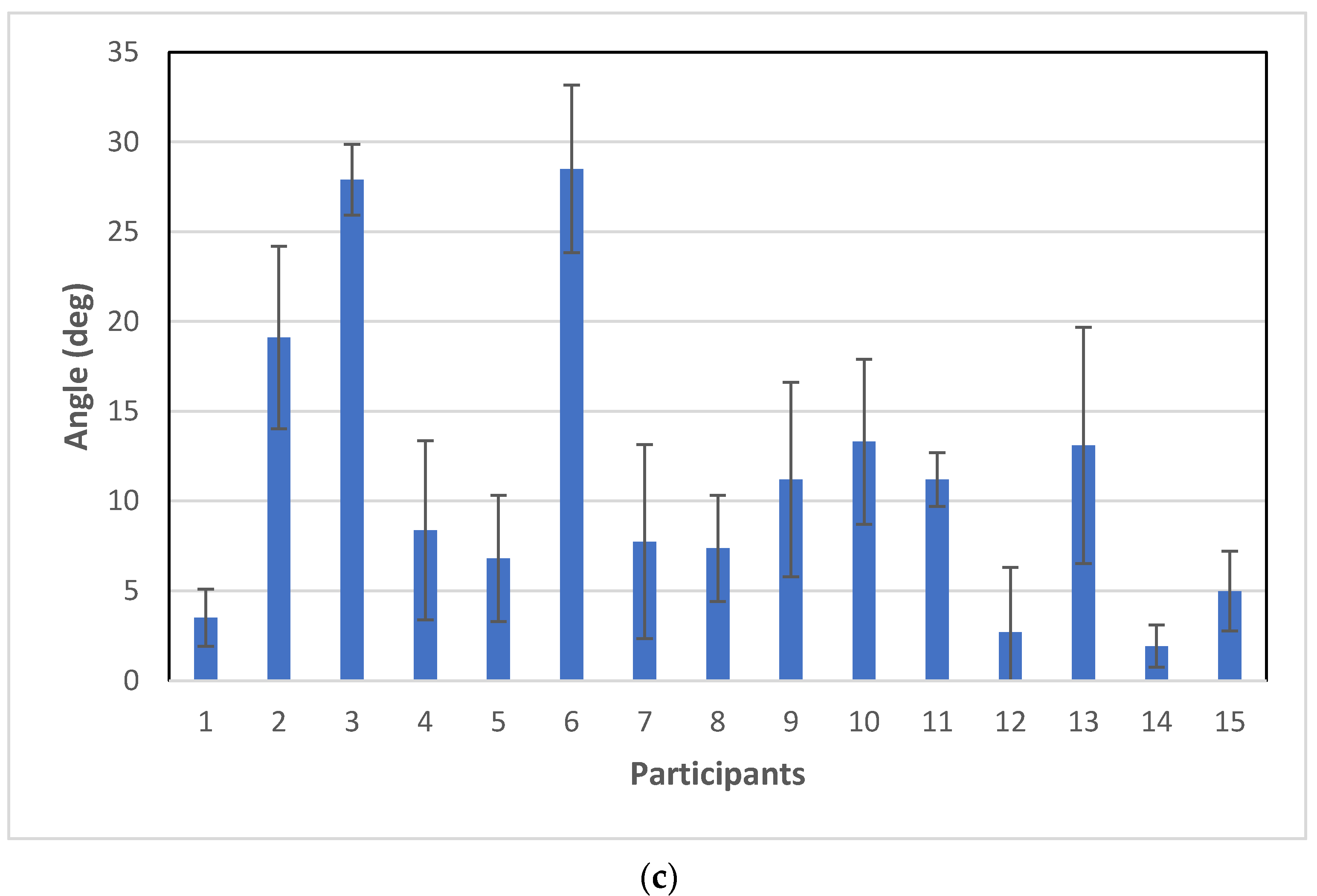
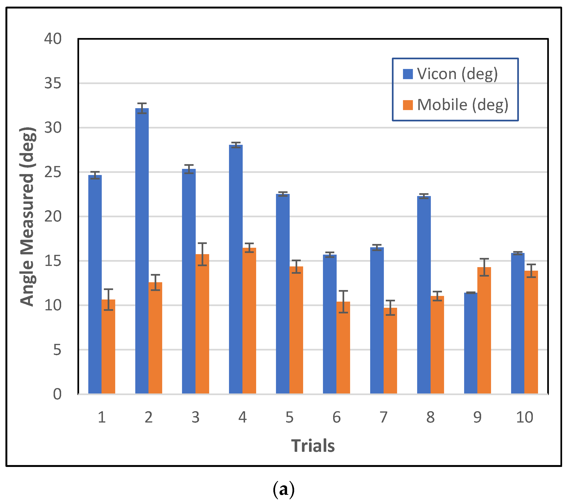
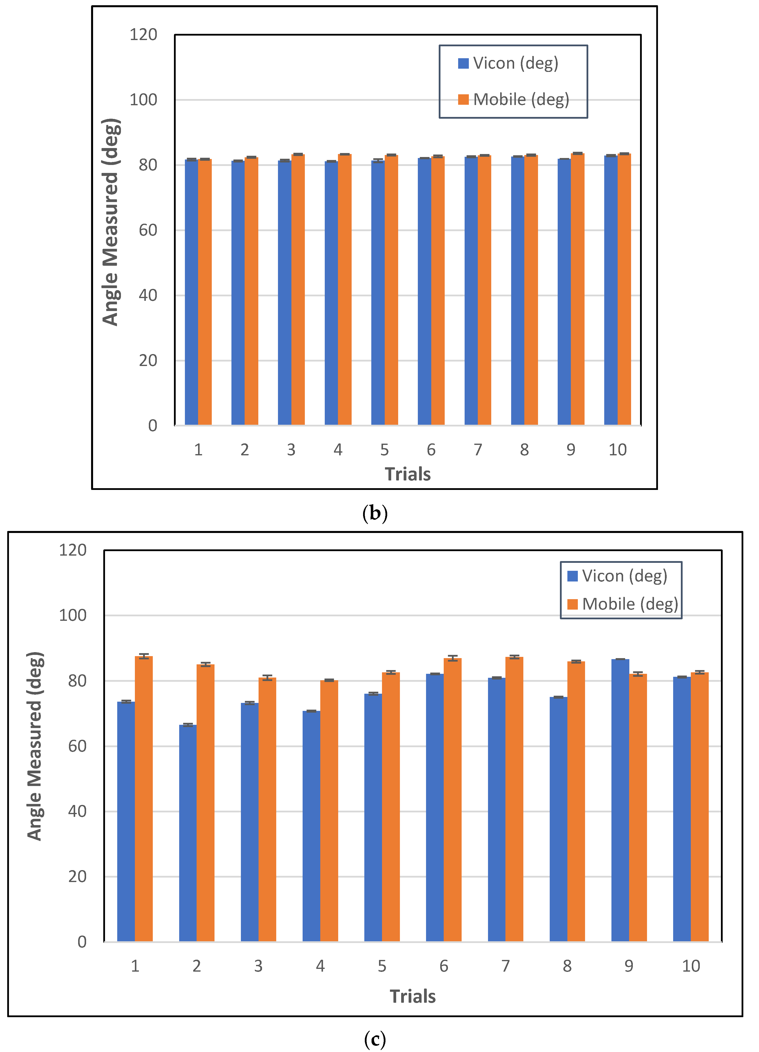
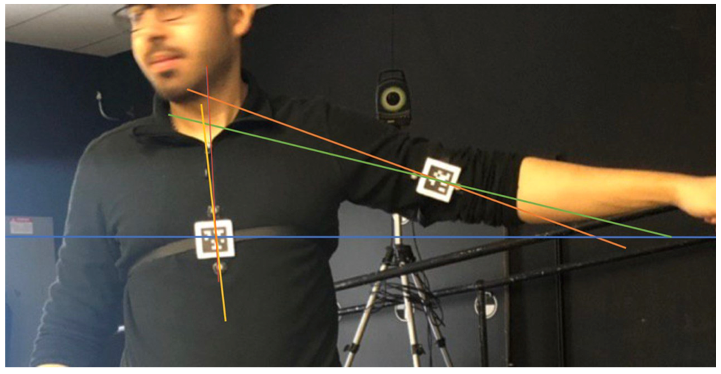
The difference between app and Vicon arm abduction measurements was not satisfactory. To investigate this further, arm abduction angle was divided into: (a) angle between torso and horizontal line, (b) angle between arm and horizontal line, and (c) angle between arm and torso. Figure 5 shows mean differences for all participants and Figure 6 shows mean differences for participant 4, highlighting differences between participants and between mean and standard deviation. Torso standard deviations (SD) were consistent but SD differed between trials for angle measurements between the arm and horizontal. Figure 7 demonstrates these differences since the line created from the reflective markers (green line) had a different angle than a line passing through the AprilTag’s center (orange line). The difference between lines was smaller for the torso reflective markers (yellow line) and a line passing through the AprilTag marker (red line).
5. Discussion
The smartphone biomechanics augmented reality app was successfully developed, implemented, and evaluated. The app tracked and displayed accurate angles, based on evaluation with a Body Opponent Bag where anthropometric measures were not affected by clothing or participant movement. Therefore, these viable angle measurements can be used for point-of-contact assessments. Evaluations with humans also demonstrated viability for posture, body symmetry, and ROM assessment, but results were not as good as the BOB analyses, indicating that measurement method improvements could be made to improve human measurement accuracy. The ability to work in real time with the AR display enables clinicians to hand hold markers for efficient measurements while interacting with patients.
Various sources of marker-based measurement error have been reported for human movement analysis, and BAR-M was also adversely affected by these errors. These include skin movement over bone, clothing movement, and difficulty locating anatomical landmarks in areas with excessive tissue [30,31,32]. For this study, participants wore regular clothing since this better reflected an actual-use scenario. One of the limitations of the BAR-M application is the inability to automatically correct for errors caused by factors such as clothing movement while quantifying human posture and ROM. Autocorrection could be one of the future research directions to reduce systematic errors caused by external factors.
5.1. Pelvis and Shoulder Measurement
For shoulder and pelvis measurements, most participants had differences between the Vicon and BAR-M of less than 2°. However, two people had differences of more than 3°. The greater differences could be due to difficulties positioning both marker sets (AprilTag and reflective markers) on the anatomical landmarks. For shoulder measurements, not holding the AprilTag flat mount in an exact vertical diamond shape on top of the reflective markers would cause an error, although the vertical diamond position enhances stability when holding a marker and aids positioning. For pelvis measurement, the greater differences could be due to the Vicon markers being taped onto clothing, since using the post adapter to locate anatomical landmarks could move clothing and thereby affect reflective marker locations. Vicon measurement standard deviation was greater than the mobile app, especially for people with more fat on their pelvic area since body mass could move and affect Vicon marker locations when the evaluator located the landmarks with the post adapter. Therefore, this research highlights the practical issues for using marker-based analysis at the point of patient contact. Since the AprilTag mount is held at the appropriate location, regardless of clothing, this approach may be more appropriate than other data-collection-based approaches where markers experience clothing-movement error (i.e., when making real-time measurements during a clinical encounter).
5.2. Arm Abduction
Arm abduction differences between Vicon and app measurements were greater than the shoulder and pelvis measurements. In some cases, arm abduction differences were more than 10°, with the maximum being 28.46°. As discussed in the previous section, this error involved both the arm and chest, hence error summation contributed to the differences (i.e., pelvis and shoulder). All errors were systematic. Chest errors could be resolved by an appropriate Velcro strap and locating tags on the participant’s back rather than chest (i.e., flatter surface). Moreover, securing the mount with tape on the skin could help since strap movement due to breathing or torso movement could be reduced. The torso location would typically be used as a reference for limb angle measurement, so this marker would benefit from being secure on the person rather than hand held.
For the arm, errors occurred due to changes in alignment between the reflective markers and AprilTags, since reflective markers moved when a participant moved their arm, predominately due to clothing movement. Therefore, the Vicon marker-based measurement had large errors and was the main contributor to differences between the smartphone output and comparator data. Clothing movement errors are well known for marker-based systems [33]. In situations where participants are not comfortable removing their clothes (i.e., cultural reason or measurement in public), measurement errors caused by clothing are likely for adhesive-based approaches [34]. An appropriate strap and AprilTag marker approach could minimize clothing-based errors, as well as holding the marker on the person.
In the literature, marker-based systems and bi-planar videoradiography were compared, and reported joint center position errors of up to 30 mm and joint rotation errors of up to 14°, with averages of 9 to 19 mm and 2.2 to 5.5°, respectively [35,36]. All motion capture systems yield the largest errors in rotation along the longitudinal axis when measuring devices such as markers placed on the skin are closer to the axis of rotation, with hip internal–external rotational errors as high as 21.8° [37,38].
Reading the most consistent angle from the mobile screen in real time provided accurate results, supporting the AR approach for pose measurement. The average difference between reading the on-screen value and calculating the average angle from saved data was less than a 0.2°. Therefore, reading instant measurements from the mobile screen is appropriate.
Fiducial markers were essential to avoid marker loss in environments with complex backgrounds and to avoid confusion between markers, since each fiducial marker is unique and more easily separated from the background. Another benefit of AprilTag markers is that marker corner coordinates are provided, which can be used to calculate a linear scale factor and enable distance measurements.
With a smartphone, a trade-off exists between image resolution and AprilTag sample rate, with sample rate decreasing for higher resolutions. The current configuration enabled pose measurement with the entire body in the field of view. Newer mobile devices with faster processors will provide faster sample rates and/or higher video resolutions, which would then enable the camera to be located further away or smaller AprilTags to be used. The BAR-M app can set the appropriate resolution for a functional frame rate across phones with differing processing capacities.
6. Conclusions
The “Biomechanics Augmented Reality—Marker” (BAR-M) application was developed and evaluated for functional application. The BAR-M application detected, tracked, and calculated anatomical angles between fiducial landmarks, in real time. Angles were displayed on-screen in real time and detailed data were stored on the mobile device. This AR smartphone app was viable for range of motion, body symmetry, and postural measurements required by clinicians and researchers, both from reading the real-time angle and postprocessing saved data. The smartphone app approach could help clinicians assess human body posture and range of motion at the point of patient contact. A successful app opens the door for many new research opportunities for 3D and dynamic postural measurement. Additionally, AprilTag3 was recently introduced [39], providing better tag detection and reduced processing algorithm time, so Z direction (depth) can be computed live without a delay [39]. Addition of the depth component could improve error correction for hand-held markers or for patient movement out of the camera plane.
Measurement methodologies could be improved to compensate for clothing and other factors that can introduce measurement error. This includes developing straps that can be quickly applied to the body for a consistent fiducial marker location and expanding the current set of adapters to make human measurement efficient for the clinician and the person being measured (e.g., curved, square, foldable adapters).
Author Contributions
All authors were fully involved in the study and preparation of the manuscript and the material within has not been and will not be submitted for publication elsewhere. All authors have read and agreed to the published version of the manuscript.
Funding
This research was funded by the Natural Sciences and Engineering Research Council of Canada, grant number 482728-2016-CREAT and the study was funded by CREATE-BEST.
Institutional Review Board Statement
The study was conducted in accordance with the Office of Research Ethics and Integrity of the University of Ottawa, and the protocol was approved by the University of Ottawa Research Ethics Board (protocol code H-09-18-909 and date of approval 3 October 2018).
Informed Consent Statement
Written informed consent was obtained from all subjects involved in the study.
Data Availability Statement
Not applicable.
Acknowledgments
The Authors would like to thank Hossein Gholizadeh for his assistance with data collection.
Conflicts of Interest
The authors declare no conflict of interest. The funders had no role in the design of the study; in the collection, analyses, or interpretation of data; in the writing of the manuscript or in the decision to publish the results.
References
- Paušić, J.; Pedišić, Ž.; Dizdar, D. Reliability of a Photographic Method for Assessing Standing Posture of Elementary School Students. J. Manip. Physiol. Ther. 2010, 33, 425–431. [Google Scholar] [CrossRef] [PubMed]
- Saleh, M.; Murdoch, G. In Defence of Gait Analysis. Observation and Measurement in Gait Assessment. J. Bone Joint Surg. Br. 1985, 67, 237–241. [Google Scholar] [CrossRef] [Green Version]
- Carse, B.; Meadows, B.; Bowers, R.; Rowe, P. Affordable Clinical Gait Analysis: An Assessment of the Marker Tracking Accuracy of a New Low-Cost Optical 3D Motion Analysis System. Physiotherapy 2013, 99, 347–351. [Google Scholar] [CrossRef] [PubMed]
- Fortin, C.; Feldman, D.E.; Cheriet, F.; Labelle, H. Validity of a Quantitative Clinical Measurement Tool of Trunk Posture in Idiopathic Scoliosis. Spine 2010, 35, 988–994. [Google Scholar] [CrossRef] [PubMed] [Green Version]
- Song, M.-H.; Godøy, R.I. How Fast Is Your Body Motion? Determining a Sufficient Frame Rate for an Optical Motion Tracking System Using Passive Markers. PLoS ONE 2016, 11, e0150993. [Google Scholar] [CrossRef] [PubMed]
- Herda, L.; Fua, P.; Plänkers, R.; Boulic, R.; Thalmann, D. Using Skeleton-Based Tracking to Increase the Reliability of Optical Motion Capture. Hum. Mov. Sci. 2001, 20, 313–341. [Google Scholar] [CrossRef] [Green Version]
- Chiari, L.; Della Croce, U.; Leardini, A.; Cappozzo, A. Human Movement Analysis Using Stereophotogrammetry: Part 2: Instrumental Errors. Gait Posture 2005, 21, 197–211. [Google Scholar] [CrossRef]
- Ezeh, C.; Holloway, C.; Carlson, T. MoRe-T2 (Mobility Research Trajectory Tracker): Validation and Application. J. Rehabil. Assist. Technol. Eng. 2016, 3, 205566831667055. [Google Scholar] [CrossRef]
- Prakash, C.; Mittal, A.; Kumar, R.; Mittal, N. Identification of Spatio-Temporal and Kinematics Parameters for 2-D Optical Gait Analysis System Using Passive Markers. In Proceedings of the 2015 International Conference on Advances in Computer Engineering and Applications, Ghaziabad, India, 19–20 March 2015; IEEE: Ghaziabad, India; pp. 143–149. [Google Scholar]
- Abu-Faraj, Z.O. Handbook of Research on Biomedical Engineering Education and Advanced Bioengineering Learning; Medical Information Science Reference: Hershey, PA, USA, 2013. [Google Scholar]
- Measurement Sciences Aurora—Measurement Sciences. Available online: https://www.ndigital.com/msci/applications/biomechanics/ (accessed on 22 May 2019).
- Lou, E.; Hill, D.L.; Raso, V.J.; Durdle, N.G. A Posture Measurement System for the Treatment of Scoliosis. In Proceedings of the 16th IEEE Instrumentation and Measurement Technology Conference, Venice, Italy, 24–26 May 1999. [Google Scholar]
- Jung, E.S.; Park, S. Prediction of Human Reach Posture Using a Neural Network for Ergonomic Man Models. Comput. Ind. Eng. 1994, 27, 369–372. [Google Scholar] [CrossRef]
- Poppe, R. Vision-Based Human Motion Analysis: An Overview. Comput. Vis. Image Underst. 2007, 108, 4–18. [Google Scholar] [CrossRef]
- Moeslund, T.B.; Hilton, A.; Krüger, V. A Survey of Advances in Vision-Based Human Motion Capture and Analysis. Comput. Vis. Image Underst. 2006, 104, 90–126. [Google Scholar] [CrossRef]
- Mathis, A.; Schneider, S.; Lauer, J.; Mathis, M.W. A Primer on Motion Capture with Deep Learning: Principles, Pitfalls, and Perspectives. Neuron 2020, 108, 44–65. [Google Scholar] [CrossRef]
- Krause, D.A.; Boyd, M.S.; Hager, A.N.; Smoyer, E.C.; Thompson, A.T.; Hollman, J.H. Reliability and Accuracy of a Goniometer Mobile Device Application for Video Measurement of the Functional Movement Screen Deep Squat Test. Int. J. Sports Phys. Ther. 2015, 10, 37–44. [Google Scholar] [PubMed]
- Lemaire, E. A Shockwave Approach for Web-Based Clinical Motion Analysis. Telemed. J. e-Health 2004, 10, 39–43. [Google Scholar] [CrossRef] [PubMed]
- Lemaire, E. Biomechanics Augmented Reality—Apps on Google Play. Available online: https://play.google.com/store/apps/details?id=ca.irrd.bar&hl=en (accessed on 24 May 2019).
- Viswakumar, A.; Rajagopalan, V.; Ray, T.; Gottipati, P.; Parimi, C. Development of a Robust, Simple, and Affordable Human Gait Analysis System Using Bottom-Up Pose Estimation with a Smartphone Camera. Front. Physiol. 2022, 12, 2424. [Google Scholar] [CrossRef] [PubMed]
- Mroz, S.; Baddour, N.; McGuirk, C.; Juneau, P.; Tu, A.; Cheung, K.; Lemaire, E. Comparing the Quality of Human Pose Estimation with BlazePose or OpenPose. In Proceedings of the 4th International. Conference on Bio-Engineering on Smart Technology, Paris, France, 8–10 December 2021. [Google Scholar] [CrossRef]
- Wang, J.; Olson, E. AprilTag 2: Efficient and Robust Fiducial Detection. In Proceedings of the IEEE International Conference on Intelligent Robots and Systems, Daejeon, Korea, 9–14 October 2016; pp. 4193–4198. [Google Scholar]
- Basiratzadeh, S.; Lemaire, E.D.; Dorrikhteh, M.; Baddour, N. Fiducial Marker Approach for Biomechanical Smartphone-Based Measurements. In Proceedings of the 2019 3rd International Conference on Bio-engineering for Smart Technologies (BioSMART), Paris, France, 24–26 April 2019; pp. 1–4. [Google Scholar]
- Olson, E. AprilTag: A Robust and Flexible Visual Fiducial System. In Proceedings of the IEEE International Conference on Robotics and Automation, Shanghai, China, 9–13 May 2011; pp. 3400–3407. [Google Scholar]
- Khan, D.; Ullah, S.; Yan, D.M.; Rabbi, I.; Richard, P.; Hoang, T.; Billinghurst, M.; Zhang, X. Robust Tracking Through the Design of High Quality Fiducial Markers: An Optimization Tool for ARToolKit. IEEE Access 2018, 6, 22421–22433. [Google Scholar] [CrossRef]
- Shabalina, K.; Magid, E.; Sagitov, A.; Li, H.; Sabirova, L. ARTag, AprilTag and CALTag Fiducial Marker Systems: Comparison in a Presence of Partial Marker Occlusion and Rotation. In Proceedings of the 14th International Conference on Informatics in Control, Automation and Robotics (ICINCO 2017), Madrid, Spain, 26–28 June 2017; Volume 2, pp. 182–191. [Google Scholar]
- Basiratzadeh, S.; Lemaire, E.D.; Baddour, N. Augmented Reality Approach for Marker-Based Posture Measurement on Smartphones. Augmented Reality Approach for Marker-Based Posture Measurement on Smartphones. In Proceedings of the 42nd Annual International Conference of the IEEE Engineering in Medicine & Biology Society (EMBC), Montreal, QC, Canada, 20–24 July 2020; IEEE: Piscataway, NJ, USA, 2020. ISBN 9781728119908. [Google Scholar]
- Kim, J.; Jun, H. Implementation of Image Processing and Augmented Reality Programs for Smart Mobile Device. In Proceedings of the 6th International Forum on Strategic Technology, IFOST 2011, Harbin, China, 22–24 August 2011; Volume 2, pp. 1070–1073. [Google Scholar]
- Merriaux, P.; Dupuis, Y.; Boutteau, R.; Vasseur, P.; Savatier, X.; Merriaux, P.; Dupuis, Y.; Boutteau, R.; Vasseur, P.; Savatier, X. A Study of Vicon System Positioning Performance. Sensors 2017, 17, 1591. [Google Scholar] [CrossRef]
- Olsen, A.M. Posture and Body Movement Perception. Acta Psychol. 2007, 19, 820–821. [Google Scholar] [CrossRef]
- Della Croce, U.; Leardini, A.; Chiari, L.; Cappozzo, A. Human Movement Analysis Using Stereophotogrammetry Part 4: Assessment of Anatomical Landmark Misplacement and Its Effects on Joint Kinematics. Gait Posture 2005, 21, 226–237. [Google Scholar] [CrossRef]
- Peters, A.; Galna, B.; Sangeux, M.; Morris, M.; Baker, R. Quantification of Soft Tissue Artifact in Lower Limb Human Motion Analysis: A Systematic Review. Gait Posture 2010, 31, 1–8. [Google Scholar] [CrossRef]
- McGinley, J.L.; Baker, R.; Wolfe, R.; Morris, M.E. The Reliability of Three-Dimensional Kinematic Gait Measurements: A Systematic Review. Gait Posture 2009, 29, 360–369. [Google Scholar] [CrossRef] [PubMed]
- Tsushima, H.; Morris, M.E.; McGinley, J. Test-Retest Reliability and Inter-Tester Reliability of Kinematic Data from a Three-Dimensional Gait Analysis System. J. Jpn. Phys. Ther. Assoc. 2003, 6, 9–17. [Google Scholar] [CrossRef] [PubMed] [Green Version]
- Miranda, D.L.; Rainbow, M.J.; Crisco, J.J.; Fleming, B.C. Kinematic Differences between Optical Motion Capture and Biplanar Videoradiography during a Jump–Cut Maneuver. J. Biomech. 2013, 46, 567–573. [Google Scholar] [CrossRef] [PubMed] [Green Version]
- Wade, L.; Needham, L.; McGuigan, P.; Bilzon, J. Applications and Limitations of Current Markerless Motion Capture Methods for Clinical Gait Biomechanics. PeerJ 2022, 10, e12995. [Google Scholar] [CrossRef]
- Kessler, S.E.; Rainbow, M.J.; Lichtwark, G.A.; Cresswell, A.G.; D’andrea, S.E.; Konow, N.; Kelly, L.A. A Direct Comparison of Biplanar Videoradiography and Optical Motion Capture for Foot and Ankle Kinematics. Front. Bioeng. Biotechnol. 2019, 7, 199. [Google Scholar] [CrossRef] [Green Version]
- Fiorentino, N.M.; Atkins, P.R.; Kutschke, M.J.; Goebel, J.M.; Foreman, K.B.; Anderson, A.E. Soft Tissue Artifact Causes Significant Errors in the Calculation of Joint Angles and Range of Motion at the Hip. Gait Posture 2017, 55, 184–190. [Google Scholar] [CrossRef]
- Krogius, M.; Haggenmiller, A.; Olson, E. Flexible Layouts for Fiducial Tags. In Proceedings of the IEEE/RSJ International Conference on Intelligent Robots and Systems (IROS), Macau, China, 3–8 November 2019. [Google Scholar]
Figure 1.
Tracking module flowchart.

Figure 2.
BAR-M measurement examples.

Figure 3.
AprilTag adapters, (a) flat mount, (b) post adapter, (c) Velcro adapter.

Figure 4.
BOB and participant measurements.

Figure 5.
Arm abduction mean absolute differences and standard deviations between Vicon angle and BAR-M saved data for all participants: (a) torso to horizontal line, (b) arm to horizontal line, (c) arm to torso.
Figure 5.
Arm abduction mean absolute differences and standard deviations between Vicon angle and BAR-M saved data for all participants: (a) torso to horizontal line, (b) arm to horizontal line, (c) arm to torso.


Figure 6.
Vicon angle and app saved data for participant 4: (a) torso to horizontal line, (b) arm to horizontal line, (c) arm to torso.
Figure 6.
Vicon angle and app saved data for participant 4: (a) torso to horizontal line, (b) arm to horizontal line, (c) arm to torso.


Figure 7.
Arm abduction errors.


Table 1.
Participant test app AR angle and stored data results.
| Participant | Average Angle Difference between Vicon and Saved BAR-M Data | Average Angle Difference between BAR-M AR Read by Human and BAR-M Saved Data | |||
|---|---|---|---|---|---|
| Pelvis | Shoulder | Arm | Pelvis | Shoulder | |
| P1 | 1.97 ± 0.60° | 0.42 ± 0.49° | 3.51 ± 1.59° | 0.12 ± 0.14° | 0.07 ± 0.06° |
| P2 | 1.09 ± 0.50° | 0.82 ± 0.21° | 19.08 ± 5.08° | 0.31 ± 0.24° | 0.07 ± 0.10° |
| P3 | 2.65 ± 0.80° | 2.77 ± 0.30° | 27.92 ± 1.98° | 0.13 ± 0.09° | 0.06 ± 0.04° |
| P4 | 2.73 ± 1.15° | 0.61 ± 0.18° | 8.37 ± 4.98° | 0.21 ± 0.18° | 0.23 ± 0.34° |
| P5 | 0.64 ± 0.56° | 0.89 ± 0.68° | 6.80 ± 3.51° | 0.20 ± 0.29° | 0.18 ± 0.18° |
| P6 | 0.78 ± 0.88° | 0.42 ± 0.31° | 28.46 ± 4.67° | 0.18 ± 0.19° | 0.09 ± 0.06° |
| P7 | 1.42 ± 0.98° | 2.85 ± 0.98° | 7.74 ± 5.40° | 0.16 ± 0.10° | 0.03 ± 0.02° |
| P8 | 1.78 ± 0.92° | 2.28 ± 0.61° | 7.37 ± 2.95° | 0.12 ± 0.11° | 0.08 ± 0.06° |
| P9 | 0.62 ± 0.46° | 0.68 ± 0.42° | 11.19 ± 5.41° | 0.16 ± 0.14° | 0.07 ± 0.07° |
| P10 | 1.68 ± 0.83° | 3.70 ± 0.53° | 13.33 ± 4.59° | 0.18 ± 0.13° | 0.12 ± 0.10° |
| P11 | 1.98 ± 0.89° | 0.35 ± 0.21° | 11.16 ± 1.49° | 0.29 ± 0.33° | 0.20 ± 0.25° |
| P12 | 0.59 ± 0.36° | 2.38 ± 1.05° | 2.71 ± 3.59° | 0.27 ± 0.26° | 0.15 ± 0.10° |
| P13 | 3.37 ± 0.72° | 0.72 ± 0.39° | 13.07 ± 6.58° | 0.21 ± 0.31° | 0.15 ± 0.14° |
| P14 | 1.72 ± 0.86° | 0.84 ± 0.69° | 1.93 ± 1.17° | 0.17 ± 0.13° | 0.07 ± 0.05° |
| P15 | 2.52 ± 0.52° | 0.44 ± 0.33° | 4.99 ± 2.22° | 0.10 ± 0.07° | 0.19 ± 0.13° |
| Average | 1.70 ± 0.23° | 1.34 ± 0.27° | 11.18 ± 3.68° | 0.19 ± 0.09° | 0.12 ± 0.09° |
| p-value | <0.001 | <0.001 | 0.71 | <0.001 | 0.83 |
Publisher’s Note: MDPI stays neutral with regard to jurisdictional claims in published maps and institutional affiliations. |
© 2022 by the authors. Licensee MDPI, Basel, Switzerland. This article is an open access article distributed under the terms and conditions of the Creative Commons Attribution (CC BY) license (https://creativecommons.org/licenses/by/4.0/).
Share and Cite
MDPI and ACS Style
Basiratzadeh, S.; Lemaire, E.D.; Baddour, N. A Novel Augmented Reality Mobile-Based Application for Biomechanical Measurement. BioMed 2022, 2, 255-269. https://doi.org/10.3390/biomed2020021
AMA Style
Basiratzadeh S, Lemaire ED, Baddour N. A Novel Augmented Reality Mobile-Based Application for Biomechanical Measurement. BioMed. 2022; 2(2):255-269. https://doi.org/10.3390/biomed2020021
Chicago/Turabian StyleBasiratzadeh, Shahin, Edward D. Lemaire, and Natalie Baddour. 2022. "A Novel Augmented Reality Mobile-Based Application for Biomechanical Measurement" BioMed 2, no. 2: 255-269. https://doi.org/10.3390/biomed2020021