
Multi-Layered Human Blood Vessels-on-Chip Design Using Double Viscous Finger Patterning

 , ,
, ,
Abstract
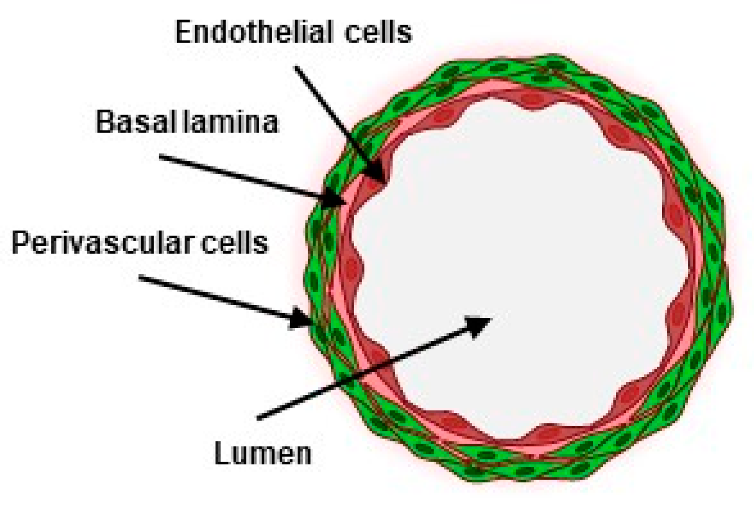
:1. Introduction
2. Materials and Methods
2.1. Microfabrication
2.2. Cell Culture
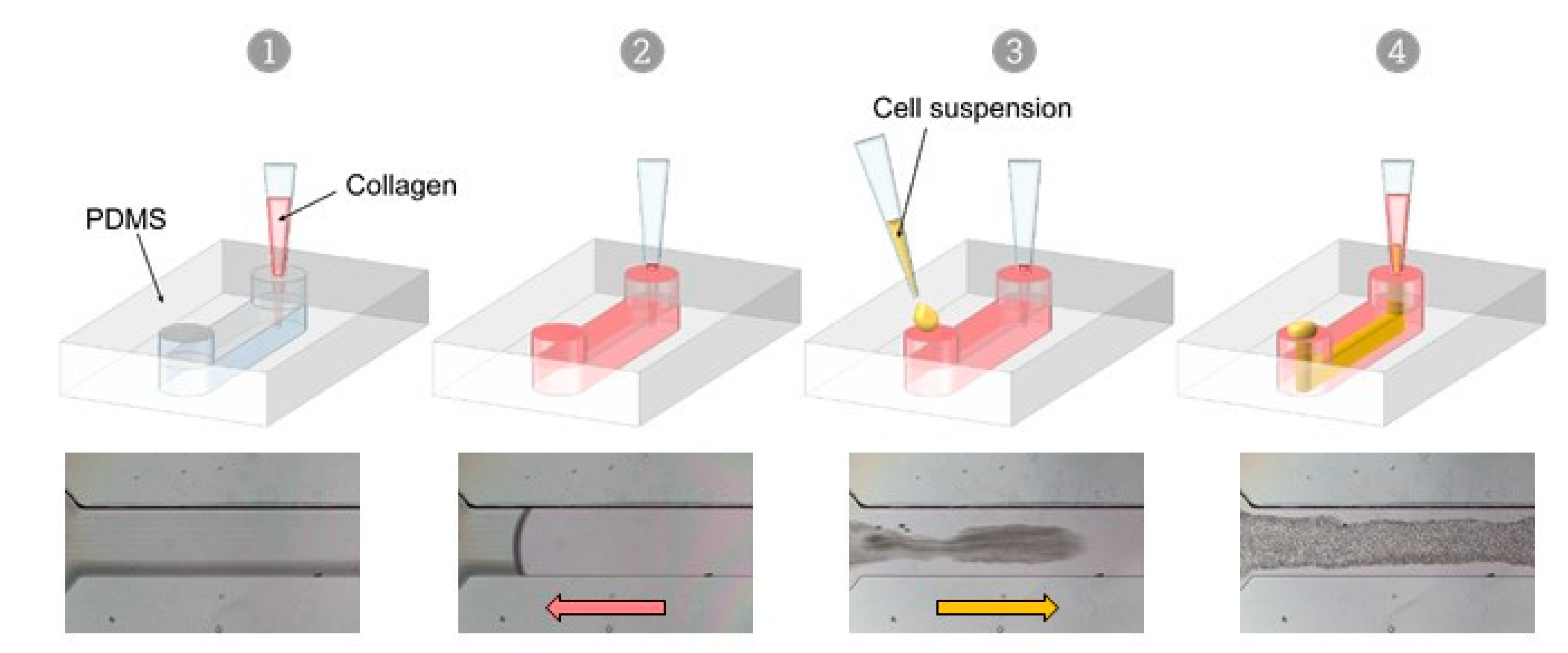
2.3. VFP Making of VoC
2.4. Permeability Assays
2.5. Adhesion of Immune Cells
2.6. Immunostainings and Microscopy
2.7. Reverse Transcription-qPCR
2.8. Statistics
3. Results
3.1. Microfabrication
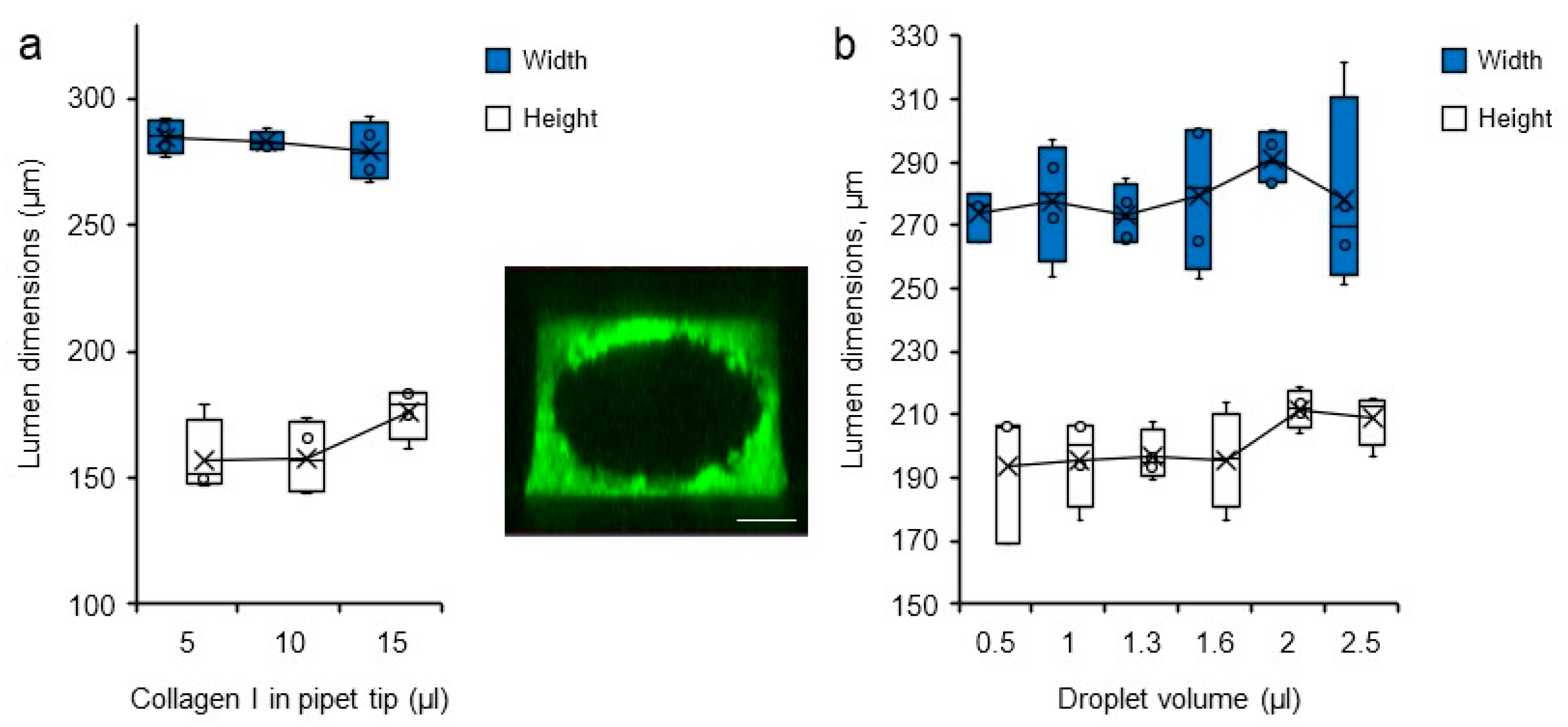
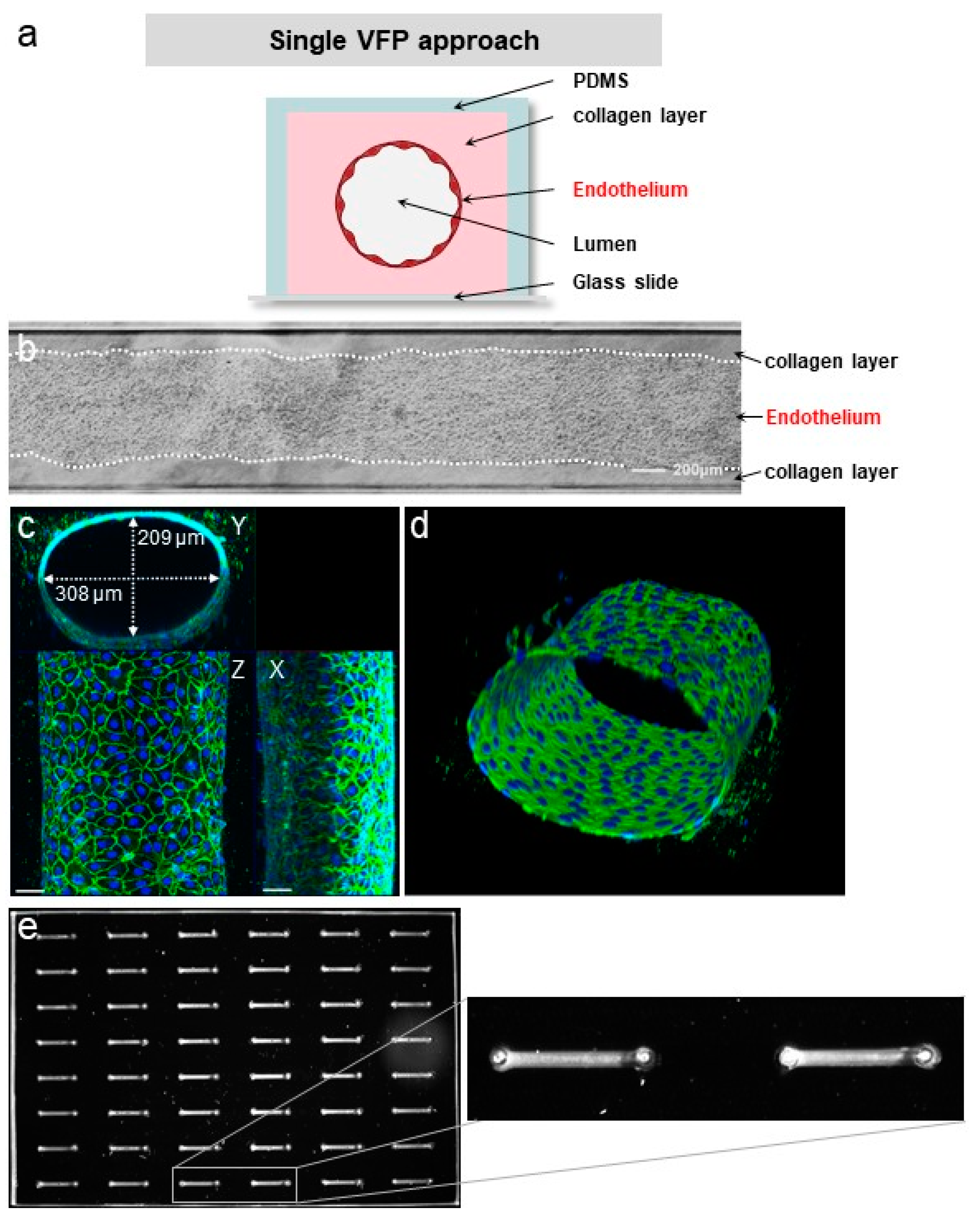
3.2. VFP Blood Vessel Design
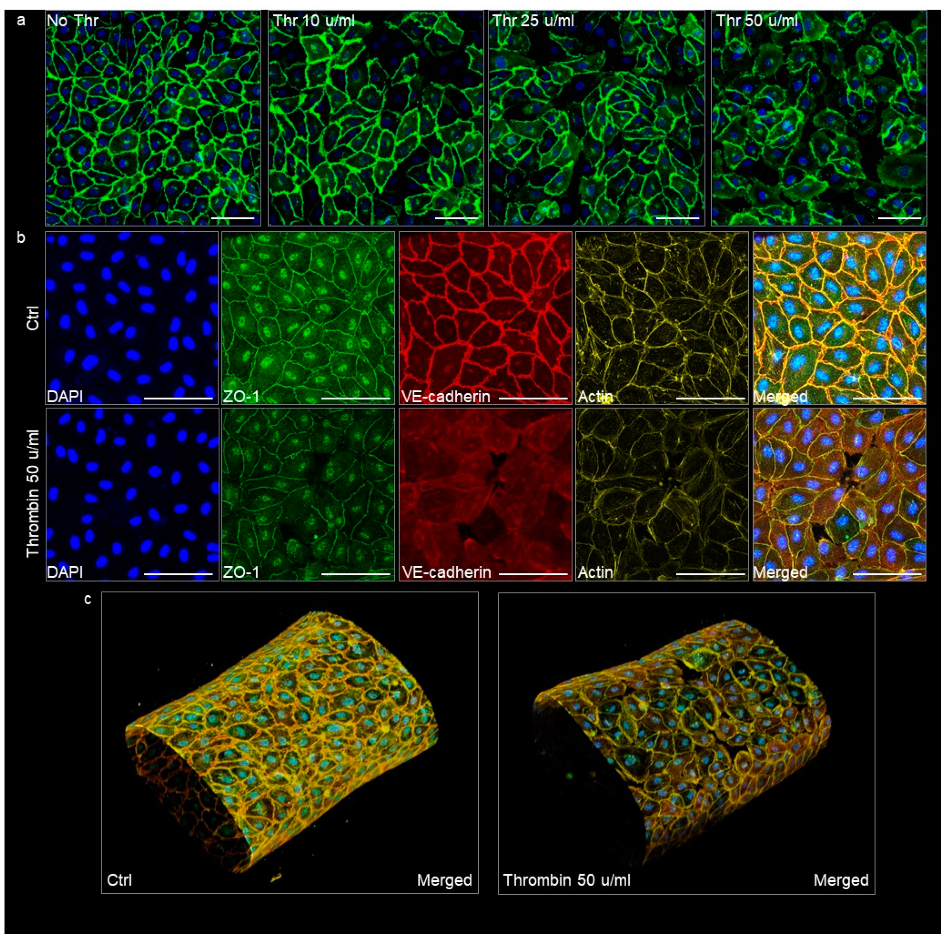
3.3. Quality of the VoC Endothelium
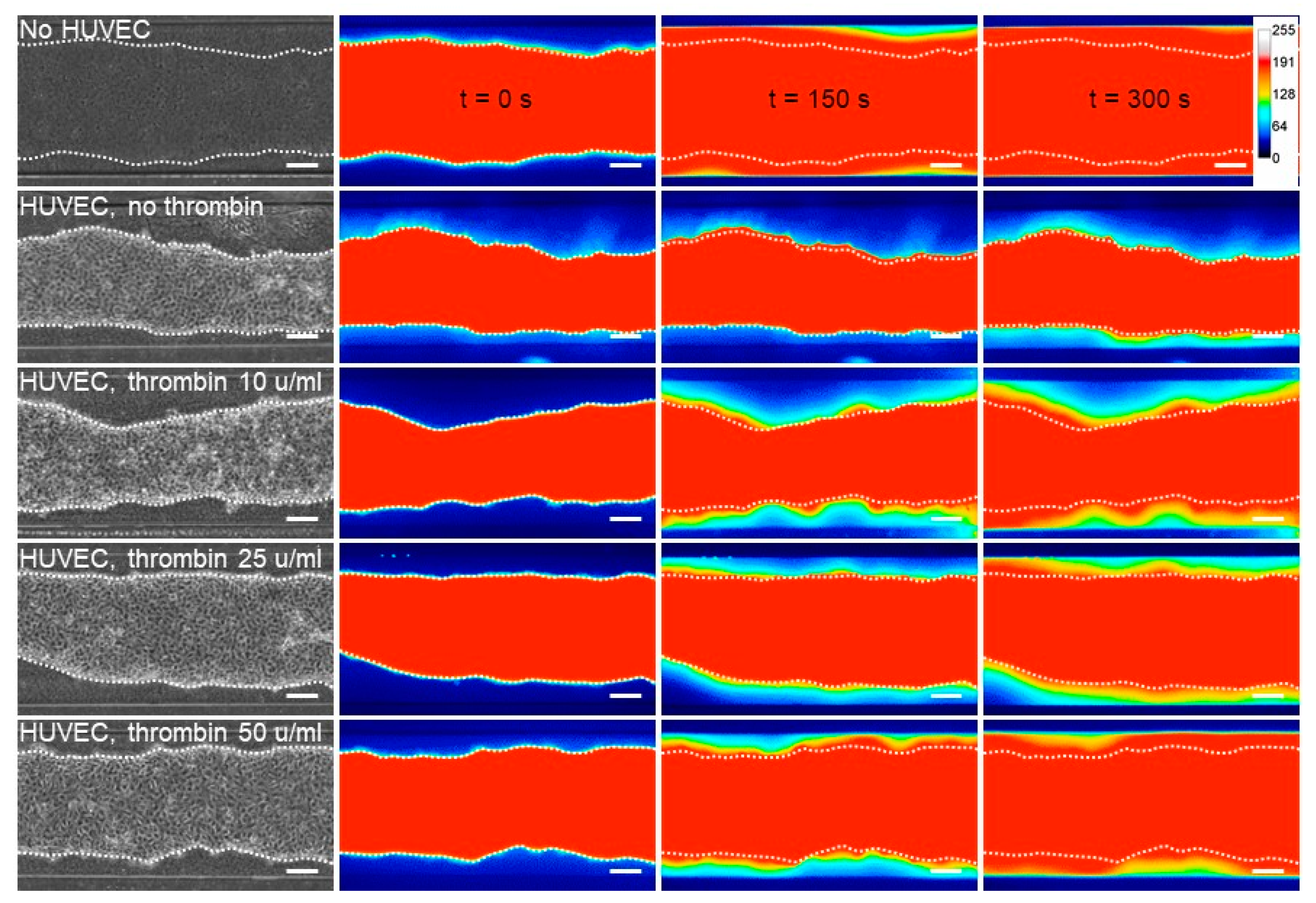
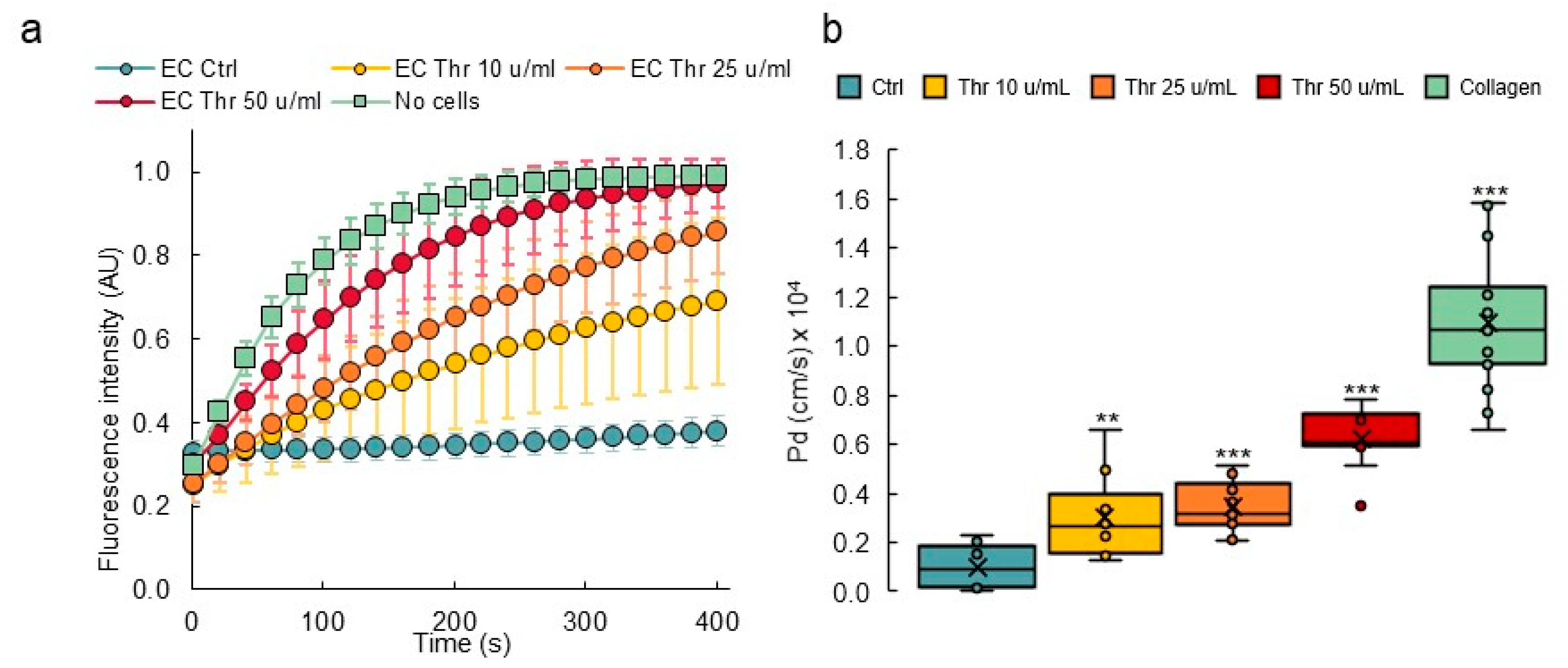
3.4. Response to Permeability Challenge
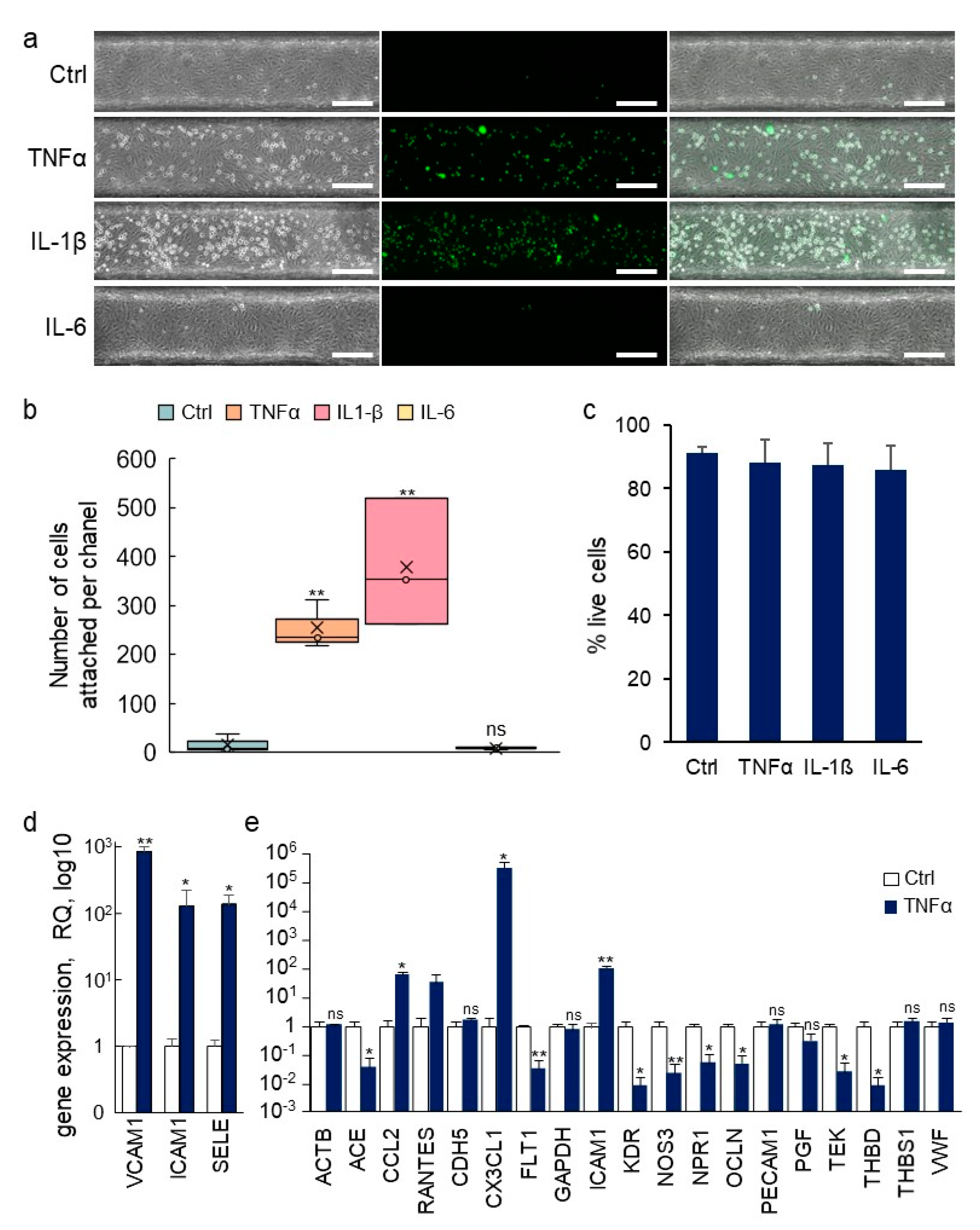
3.5. Inflammatory Activation of Blood Vessel Endothelium
3.6. Transcriptomic Analyses of Single Vessels
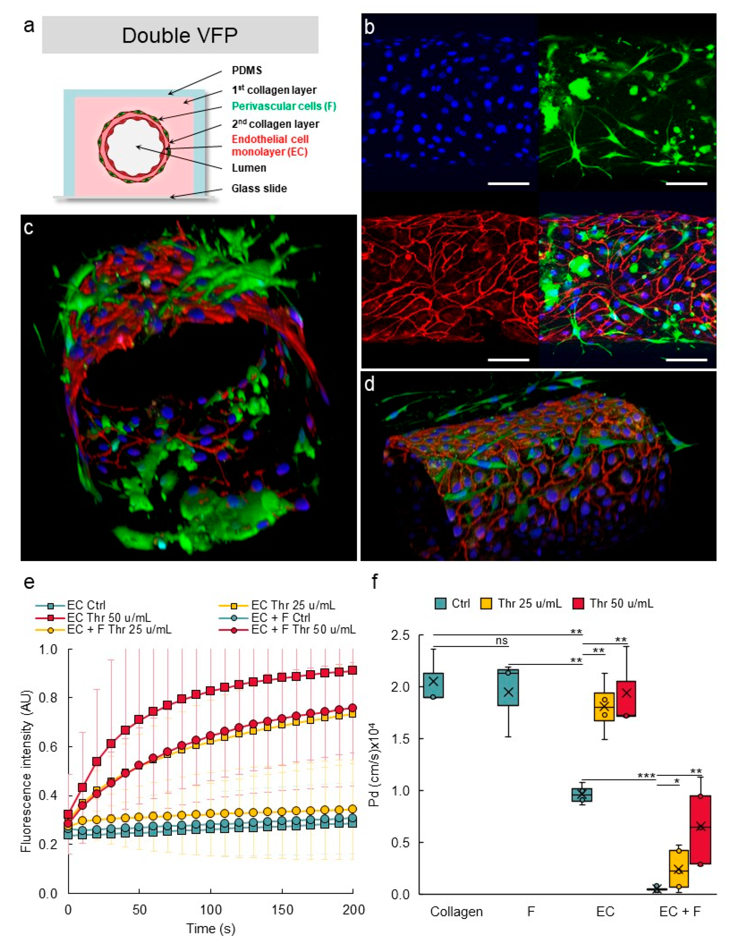
3.7. Establishing Multilayered Vessels by the Use of Double VFP
3.8. Perivascular Cells Participate in the Tightness of the Vascular Barrier
4. Discussion
Supplementary Materials
Author Contributions
Funding
Institutional Review Board Statement
Informed Consent Statement
Data Availability Statement
Acknowledgments
Conflicts of Interest
References
- Ricard, N.; Bailly, S.; Guignabert, C.; Simons, M. The quiescent endothelium: Signalling pathways regulating organ-specific endothelial normalcy. Nat. Rev. Cardiol. 2021, 18, 565–580. [Google Scholar] [CrossRef] [PubMed]
- Muller, W.A. Mechanisms of Transendothelial Migration of Leukocytes. Circ. Res. 2009, 105, 223–230. [Google Scholar] [CrossRef] [PubMed] [Green Version]
- Lampugnani, M.G.; Dejana, E.; Giampietro, C. Vascular Endothelial (VE)-Cadherin, Endothelial Adherens Junctions, and Vascular Disease. Cold Spring Harb. Perspect. Biol. 2018, 10, a029322. [Google Scholar] [CrossRef] [PubMed]
- Curry, F.-R.E.; Adamson, R.H. Vascular permeability modulation at the cell, microvessel, or whole organ level: Towards closing gaps in our knowledge. Cardiovasc. Res. 2010, 87, 218–229. [Google Scholar] [CrossRef] [Green Version]
- Dejana, E.; Tournier-Lasserve, E.; Weinstein, B.M. The Control of Vascular Integrity by Endothelial Cell Junctions: Molecular Basis and Pathological Implications. Dev. Cell 2009, 16, 209–221. [Google Scholar] [CrossRef] [Green Version]
- Komarova, Y.; Malik, A.B. Regulation of Endothelial Permeability via Paracellular and Transcellular Transport Pathways. Annu. Rev. Physiol. 2010, 72, 463–493. [Google Scholar] [CrossRef]
- Le Guelte, A.; Dwyer, J.; Gavard, J. Jumping the barrier: VE-cadherin, VEGF and other angiogenic modifiers in cancer. Biol. Cell 2011, 103, 593–605. [Google Scholar] [CrossRef]
- Herberman, R.B.; Nunn, M.E.; Holden, H.T.; Lavrin, D.H. Natural cytotoxic reactivity of mouse lymphoid cells against syngeneic and allogeneic tumors. II. Characterization of effector cells. Int. J. Cancer 1975, 16, 230–239. [Google Scholar] [CrossRef]
- Shrikant, P.; Mescher, M.F. Control of syngeneic tumor growth by activation of CD8+ T cells: Efficacy is limited by migration away from the site and induction of nonresponsiveness. J. Immunol. 1999, 162, 2858–2866. [Google Scholar] [PubMed]
- Castermans, K.; Griffioen, A. Tumor blood vessels, a difficult hurdle for infiltrating leukocytes. Biochim. Biophys. Acta 2007, 1776, 160–174. [Google Scholar] [CrossRef]
- Koebel, C.M.; Vermi, W.; Swann, J.B.; Zerafa, N.; Rodig, S.J.; Old, L.J.; Smyth, M.J.; Schreiber, R.D. Adaptive immunity maintains occult cancer in an equilibrium state. Nature 2007, 450, 903–907. [Google Scholar] [CrossRef] [PubMed]
- Han, S.; Yan, J.-J.; Shin, Y.; Jeon, J.J.; Won, J.; Jeong, H.E.; Kamm, R.D.; Kim, Y.-J.; Chung, S. A versatile assay for monitoring in vivo-like transendothelial migration of neutrophils. Lab Chip 2012, 12, 3861–3865. [Google Scholar] [CrossRef]
- Shin, Y.; Han, S.; Jeon, J.S.; Yamamoto, K.; Zervantonakis, I.K.; Sudo, R.; Kamm, R.D.; Chung, S. Microfluidic assay for simultaneous culture of multiple cell types on surfaces or within hydrogels. Nat. Protoc. 2012, 7, 1247–1259. [Google Scholar] [CrossRef] [PubMed] [Green Version]
- Li, X.; Xu, S.; He, P.; Liu, Y. In Vitro Recapitulation of Functional Microvessels for the Study of Endothelial Shear Response, Nitric Oxide and [Ca2+]i. PLoS ONE 2015, 10, e0126797. [Google Scholar] [CrossRef]
- Hosseini, V.; Mallone, A.; Nasrollahi, F.; Ostrovidov, S.; Nasiri, R.; Mahmoodi, M.; Haghniaz, R.; Baidya, A.; Salek, M.M.; Darabi, M.A.; et al. Healthy and diseased in vitro models of vascular systems. Lab Chip 2021, 21, 641–659. [Google Scholar] [CrossRef] [PubMed]
- Chrobak, K.M.; Potter, D.R.; Tien, J. Formation of perfused, functional microvascular tubes in vitro. Microvasc. Res. 2006, 71, 185–196. [Google Scholar] [CrossRef] [PubMed]
- Zheng, Y.; Chen, J.; Craven, M.; Choi, N.W.; Totorica, S.; Diaz-Santana, A.; Kermani, P.; Hempstead, B.; Fischbach-Teschl, C.; López, J.A.; et al. In vitro microvessels for the study of angiogenesis and thrombosis. Proc. Natl. Acad. Sci. USA 2012, 109, 9342–9347. [Google Scholar] [CrossRef] [Green Version]
- Alimperti, S.; Mirabella, T.; Bajaj, V.; Polacheck, W.; Pirone, D.M.; Duffield, J.; Eyckmans, J.; Assoian, R.K.; Chen, C.S. Three-dimensional biomimetic vascular model reveals a RhoA, Rac1, and N-cadherin balance in mural cell–endothelial cell-regulated barrier function. Proc. Natl. Acad. Sci. USA 2017, 114, 8758–8763. [Google Scholar] [CrossRef] [Green Version]
- Hasan, A.; Paul, A.; Memic, A.; Khademhosseini, A. A multilayered microfluidic blood vessel-like structure. Biomed. Microdevices 2015, 17, 88. [Google Scholar] [CrossRef] [PubMed] [Green Version]
- De Graaf, M.N.S.; Cochrane, A.; Hil, F.E.V.D.; Buijsman, W.; Van Der Meer, A.D.; Berg, A.V.D.; Mummery, C.L.; Orlova, V.V. Scalable microphysiological system to model three-dimensional blood vessels. APL Bioeng. 2019, 3, 026105. [Google Scholar] [CrossRef] [PubMed]
- Ando, Y.; Oh, J.M.; Zhao, W.; Tran, M.; Shen, K. Engineering a Vascularized Hypoxic Tumor Model for Therapeutic Assessment. Cells 2021, 10, 2201. [Google Scholar] [CrossRef] [PubMed]
- Yu, F.; Kumar, N.D.S.; Foo, L.C.; Ng, S.H.; Hunziker, W.; Choudhury, D. A pump-free tricellular blood–brain barrier on-a-chip model to understand barrier property and evaluate drug response. Biotechnol. Bioeng. 2020, 117, 1127–1136. [Google Scholar] [CrossRef] [PubMed]
- Abramoff, M.D. Image Processing with ImageJ. Biophotonics Int. 2004, 11, 36–42. [Google Scholar]
- Livak, K.J.; Schmittgen, T.D. Analysis of Relative Gene Expression Data Using Real-Time Quantitative PCR and the 2−ΔΔCT Method. Methods 2001, 25, 402–408. [Google Scholar] [CrossRef] [PubMed]
- Chevalier, C.; BEN Amar, M.; Bonn, D.; Lindner, A. Inertial effects on Saffman-Taylor viscous fingering. J. Fluid Mech. 2006, 552, 83–97. [Google Scholar] [CrossRef] [Green Version]
- Saffman, P.G.; Taylor, G.I. The penetration of a fluid into a porous medium or Hele-Shaw cell containing a more viscous liquid. Proc. R. Soc. Lond. A Math. Phys. Eng. Sci. 1958, 245, 312–329. [Google Scholar] [CrossRef]
- Bischel, L.L.; Lee, S.-H.; Beebe, D.J. A Practical Method for Patterning Lumens through ECM Hydrogels via Viscous Finger Patterning. J. Lab. Autom. 2012, 17, 96–103. [Google Scholar] [CrossRef] [Green Version]
- Herland, A.; van der Meer, A.D.; FitzGerald, E.A.; Park, T.-E.; Sleeboom, J.J.F.; Ingber, D.E. Distinct Contributions of Astrocytes and Pericytes to Neuroinflammation Identified in a 3D Human Blood-Brain Barrier on a Chip. PLoS ONE 2016, 11, e0150360. [Google Scholar] [CrossRef] [PubMed] [Green Version]
- Polacheck, W.J.; Kutys, M.L.; Tefft, J.B.; Chen, C.S. Microfabricated blood vessels for modeling the vascular transport barrier. Nat. Protoc. 2019, 14, 1425–1454. [Google Scholar] [CrossRef]
- Wettschureck, N.; Strilic, B.; Offermanns, S. Passing the Vascular Barrier: Endothelial Signaling Processes Controlling Extravasation. Physiol. Rev. 2019, 99, 1467–1525. [Google Scholar] [CrossRef]
- Romano, M.; Sironi, M.; Toniatti, C.; Polentarutti, N.; Fruscella, P.; Ghezzi, P.; Faggioni, R.; Luini, W.; van Hinsbergh, V.; Sozzani, S.; et al. Role of IL-6 and Its Soluble Receptor in Induction of Chemokines and Leukocyte Recruitment. Immunity 1997, 6, 315–325. [Google Scholar] [CrossRef] [Green Version]
- Magder, S.; Neculcea, J.; Sladek, R.; Neculcea, V. Lipopolysaccharide and TNF-α Produce Very Similar Changes in Gene Expression in Human Endothelial Cells. J. Vasc. Res. 2006, 43, 447–461. [Google Scholar] [CrossRef] [PubMed]
- Murakami, T.; Mataki, C.; Nagao, C.; Umetani, M.; Wada, Y.; Ishii, M.; Tsutsumi, S.; Kohro, T.; Saiura, A.; Aburatani, H.; et al. The Gene Expression Profile of Human Umbilical Vein Endothelial Cells Stimulated by Tumor Necrosis Factor Alpha Using DNA Microarray Analysis. J. Atheroscler. Thromb. 2000, 7, 39–44. [Google Scholar] [CrossRef] [Green Version]
- Viemann, D.; Goebeler, M.; Schmid, S.; Klimmek, K.; Sorg, C.; Ludwig, S.; Roth, J. Transcriptional profiling of IKK2/NF-κB—and p38 MAP kinasedependent gene expression in TNF-α—stimulated primary human endothelial cells. Blood 2004, 103, 3365–3373. [Google Scholar] [CrossRef] [PubMed] [Green Version]
- Yang, Y.-Y.; Hu, C.-J.; Chang, S.-M.; Tai, T.-Y.; Leu, S.-J. Aspirin inhibits monocyte chemoattractant protein-1 and interleukin-8 expression in TNF-α stimulated human umbilical vein endothelial cells. Atherosclerosis 2004, 174, 207–213. [Google Scholar] [CrossRef] [PubMed]
- Yang, H.; Li, M.; Chai, H.; Yan, S.; Zhang, R.; Yao, Q.; Chen, C. Expression and regulation of neuropilins and VEGF receptors byTNF-α in human endothelial cells. J. Surg. Res. 2004, 122, 249–255. [Google Scholar] [CrossRef]
- Saijonmaa, O.; Nyman, T.; Fyhrquist, F. Downregulation of Angiotensin-Converting Enzyme by Tumor Necrosis Factor-α and Interleukin-1β in Cultured Human Endothelial Cells. J. Vasc. Res. 2001, 38, 370–378. [Google Scholar] [CrossRef]
- Baluk, P.; Hashizume, H.; McDonald, D.M. Cellular abnormalities of blood vessels as targets in cancer. Curr. Opin. Genet. Dev. 2005, 15, 102–111. [Google Scholar] [CrossRef]
- Sweeney, M.; Foldes, G. It Takes Two: Endothelial-Perivascular Cell Cross-Talk in Vascular Development and Disease. Front. Cardiovasc. Med. 2018, 5, 154. [Google Scholar] [CrossRef]
- Hsu, Y.-H.; Moya, M.L.; Hughes, C.C.W.; Georgea, S.C.; Lee, A.P. A microfluidic platform for generating large-scale nearly identical human microphysiological vascularized tissue arrays. Lab Chip 2013, 13, 2990–2998. [Google Scholar] [CrossRef] [Green Version]
- Chen, M.B.; Whisler, J.A.; Jeon, J.S.; Kamm, R.D. Mechanisms of tumor cell extravasation in an in vitro microvascular network platform. Integr. Biol. 2013, 5, 1262. [Google Scholar] [CrossRef] [PubMed] [Green Version]
- Armulik, A.; Genové, G.; Betsholtz, C. Pericytes: Developmental, Physiological, and Pathological Perspectives, Problems, and Promises. Dev. Cell 2011, 21, 193–215. [Google Scholar] [CrossRef] [Green Version]
- Díaz-Flores, L.; Gutiérrez, R.; Madrid, J.F.; Varela, H.; Valladares, F.; Acosta, E.; Martín-Vasallo, P.; Díaz-Flores, L., Jr. Pericytes. Morphofunction, interactions and pathology in a quiescent and activated mesenchymal cell niche. Histol. Histopathol. 2009, 24, 909–969. [Google Scholar] [CrossRef] [PubMed]
- Newman, A.C.; Nakatsu, M.N.; Chou, W.; Gershon, P.D.; Hughes, C.C.W. The requirement for fibroblasts in angiogenesis: Fibroblast-derived matrix proteins are essential for endothelial cell lumen formation. Mol. Biol. Cell 2011, 22, 3791–3800. [Google Scholar] [CrossRef] [PubMed]
- Margolis, E.A.; Cleveland, D.S.; Kong, Y.P.; Beamish, J.A.; Wang, W.Y.; Baker, B.M.; Putnam, A.J. Stromal cell identity modulates vascular morphogenesis in a microvasculature-on-a-chip platform. Lab Chip 2021, 21, 1150–1163. [Google Scholar] [CrossRef]
- Daneman, R.; Zhou, L.; Kebede, A.A.; Barres, B.A. Pericytes are required for blood-brain barrier integrity during embryogenesis. Nature 2010, 468, 562–566. [Google Scholar] [CrossRef] [Green Version]
- Armulik, A.; Genové, G.; Mäe, M.; Nisancioglu, M.H.; Wallgard, E.; Niaudet, C.; He, L.; Norlin, J.; Lindblom, P.; Strittmatter, K.; et al. Pericytes regulate the blood-brain barrier. Nature 2010, 468, 557–561. [Google Scholar] [CrossRef] [Green Version]
- Hamzah, J.; Jugold, M.; Kiessling, F.; Rigby, P.J.; Manzur, M.; Marti, H.H.; Rabie, T.; Kaden, S.; Gröne, H.-J.; Hämmerling, G.J.; et al. Vascular normalization in Rgs5-deficient tumours promotes immune destruction. Nature 2008, 453, 410–414. [Google Scholar] [CrossRef]
- Corada, M.; Mariotti, M.; Thurston, G.; Smith, K.; Kunkel, R.; Brockhaus, M.; Lampugnani, M.G.; Martin-Padura, I.; Stoppacciaro, A.; Ruco, L.; et al. Vascular endothelial–cadherin is an important determinant of microvascular integrity in vivo. Proc. Natl. Acad. Sci. USA 1999, 96, 9815–9820. [Google Scholar] [CrossRef] [PubMed] [Green Version]
- Rabiet, M.-J.; Plantier, J.-L.; Rival, Y.; Genoux, Y.; Lampugnani, M.-G.; Dejana, E. Thrombin-Induced Increase in Endothelial Permeability Is Associated with Changes in Cell-to-Cell Junction Organization. Arterioscler. Thromb. Vasc. Biol. 1996, 16, 488–496. [Google Scholar] [CrossRef]
- Katsuno, T.; Umeda, K.; Matsui, T.; Hata, M.; Tamura, A.; Itoh, M.; Takeuchi, K.; Fujimori, T.; Nabeshima, Y.-I.; Noda, T.; et al. Deficiency of Zonula Occludens-1 Causes Embryonic Lethal Phenotype Associated with Defected Yolk Sac Angiogenesis and Apoptosis of Embryonic Cells. Mol. Biol. Cell 2008, 19, 2465–2475. [Google Scholar] [CrossRef] [PubMed] [Green Version]
- Tornavaca, O.; Chia, M.; Dufton, N.; Almagro, L.O.; Conway, D.E.; Randi, A.M.; Schwartz, M.A.; Matter, K.; Balda, M.S. ZO-1 controls endothelial adherens junctions, cell-cell tension, angiogenesis, and barrier formation. J. Cell Biol. 2015, 208, 821–838. [Google Scholar] [CrossRef] [PubMed] [Green Version]
- Pinte, S.; Caetano, B.; Le Bras, A.; Havet, C.; Villain, G.; Dernayka, R.; Duez, C.; Mattot, V.; Soncin, F. Endothelial Cell Activation Is Regulated by Epidermal Growth Factor-like Domain 7 (Egfl7) during Inflammation. J. Biol. Chem. 2016, 291, 24017–24028. [Google Scholar] [CrossRef] [PubMed] [Green Version]
- Fleischer, S.; Tavakol, D.N.; Vunjak-Novakovic, G. Engineered Microvasculature: From Arteries to Capillaries: Approaches to Engineering Human Vasculature (Adv. Funct. Mater. 37/2020). Adv. Funct. Mater. 2020, 30, 2070247. [Google Scholar] [CrossRef]
- Pauty, J.; Usuba, R.; Cheng, I.G.; Hespel, L.; Takahashi, H.; Kato, K.; Kobayashi, M.; Nakajima, H.; Lee, E.; Yger, F.; et al. A Vascular Endothelial Growth Factor-Dependent Sprouting Angiogenesis Assay Based on an In Vitro Human Blood Vessel Model for the Study of Anti-Angiogenic Drugs. EBioMedicine 2018, 27, 225–236. [Google Scholar] [CrossRef] [PubMed] [Green Version]
- Usuba, R.; Pauty, J.; Soncin, F.; Matsunaga, Y.T. EGFL7 regulates sprouting angiogenesis and endothelial integrity in a human blood vessel model. Biomaterials 2019, 197, 305–316. [Google Scholar] [CrossRef] [PubMed]
- Kocal, G.C.; Guven, S.; Foygel, K.; Goldman, A.; Chen, P.; Sengupta, S.; Paulmurugan, R.; Baskin, Y.; Demirci, U. Dynamic Microenvironment Induces Phenotypic Plasticity of Esophageal Cancer Cells Under Flow. Sci. Rep. 2016, 6, 38221. [Google Scholar] [CrossRef] [Green Version]


| Microchannel Design | Measured Height | Measured Width |
|---|---|---|
| 0.4 mm (h) × 0.4 mm (w) | 395.8 ± 2.3 µm (n = 30) | 398.0 ± 4.4 µm (n = 30) |
| 0.3 mm (h) × 1 mm (w) | 292.0 ± 2.6 µm (n = 30) | 993.5 ± 7.4 µm (n = 30) |
| Microchannel | Lumen Diameter |
|---|---|
| 0.4 mm (h) × 0.4 mm (w) | 351 ± 31 µm (n = 20) |
| 0.3 mm (h) × 1 mm (w) | 700 ± 54 µm (n = 35) |
Publisher’s Note: MDPI stays neutral with regard to jurisdictional claims in published maps and institutional affiliations. |
© 2022 by the authors. Licensee MDPI, Basel, Switzerland. This article is an open access article distributed under the terms and conditions of the Creative Commons Attribution (CC BY) license (https://creativecommons.org/licenses/by/4.0/).
Share and Cite
Delannoy, E.; Tellier, G.; Cholet, J.; Leroy, A.M.; Treizebré, A.; Soncin, F. Multi-Layered Human Blood Vessels-on-Chip Design Using Double Viscous Finger Patterning. Biomedicines 2022, 10, 797. https://doi.org/10.3390/biomedicines10040797
Delannoy E, Tellier G, Cholet J, Leroy AM, Treizebré A, Soncin F. Multi-Layered Human Blood Vessels-on-Chip Design Using Double Viscous Finger Patterning. Biomedicines. 2022; 10(4):797. https://doi.org/10.3390/biomedicines10040797
Chicago/Turabian StyleDelannoy, Elise, Géraldine Tellier, Juliette Cholet, Alice M. Leroy, Anthony Treizebré, and Fabrice Soncin. 2022. "Multi-Layered Human Blood Vessels-on-Chip Design Using Double Viscous Finger Patterning" Biomedicines 10, no. 4: 797. https://doi.org/10.3390/biomedicines10040797