
Analysis of a Stress-Strain State of a Cylindrical Tank Wall Vertical Field Joint Zone

 and
and
Abstract
:1. Introduction
2. Materials and Methods
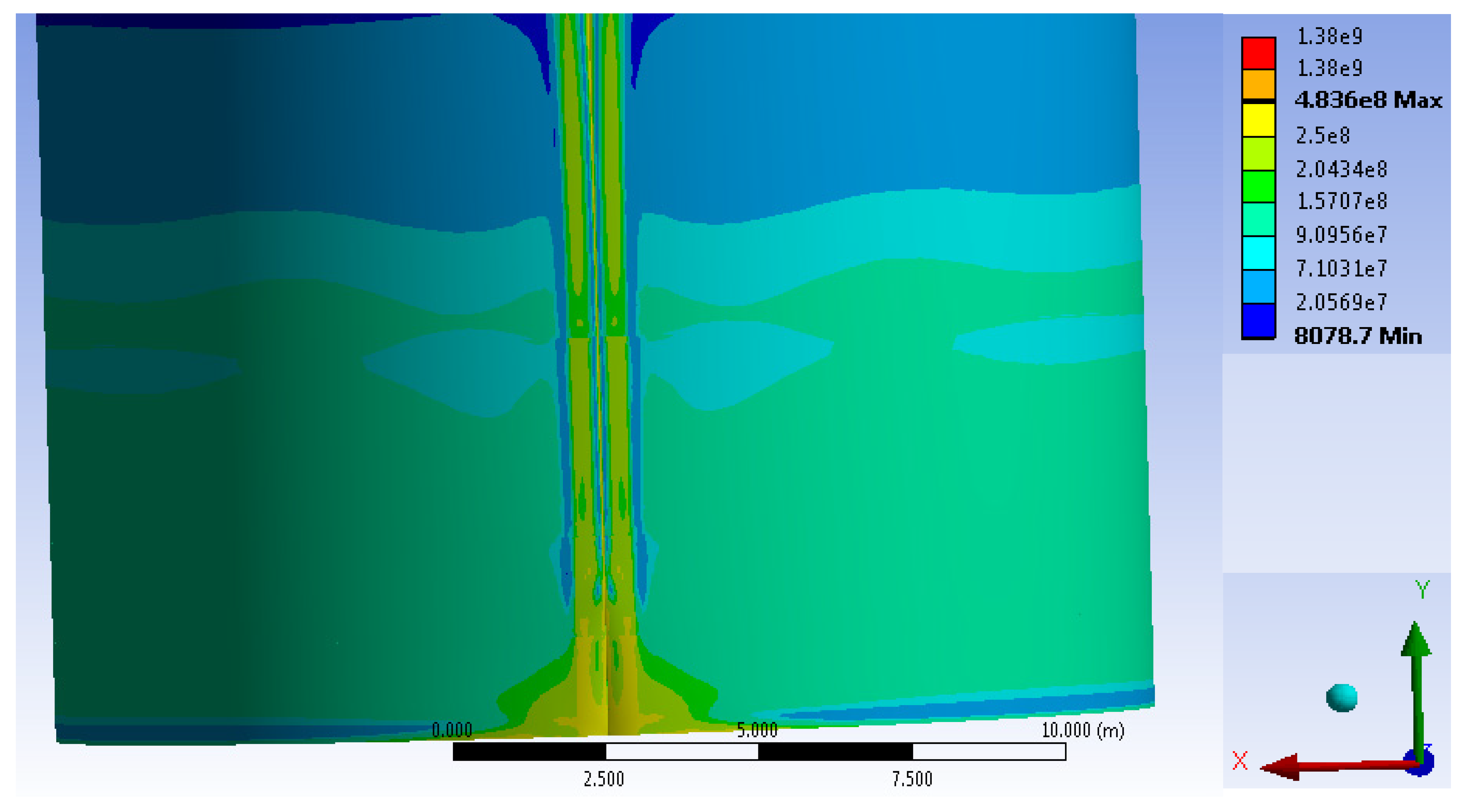
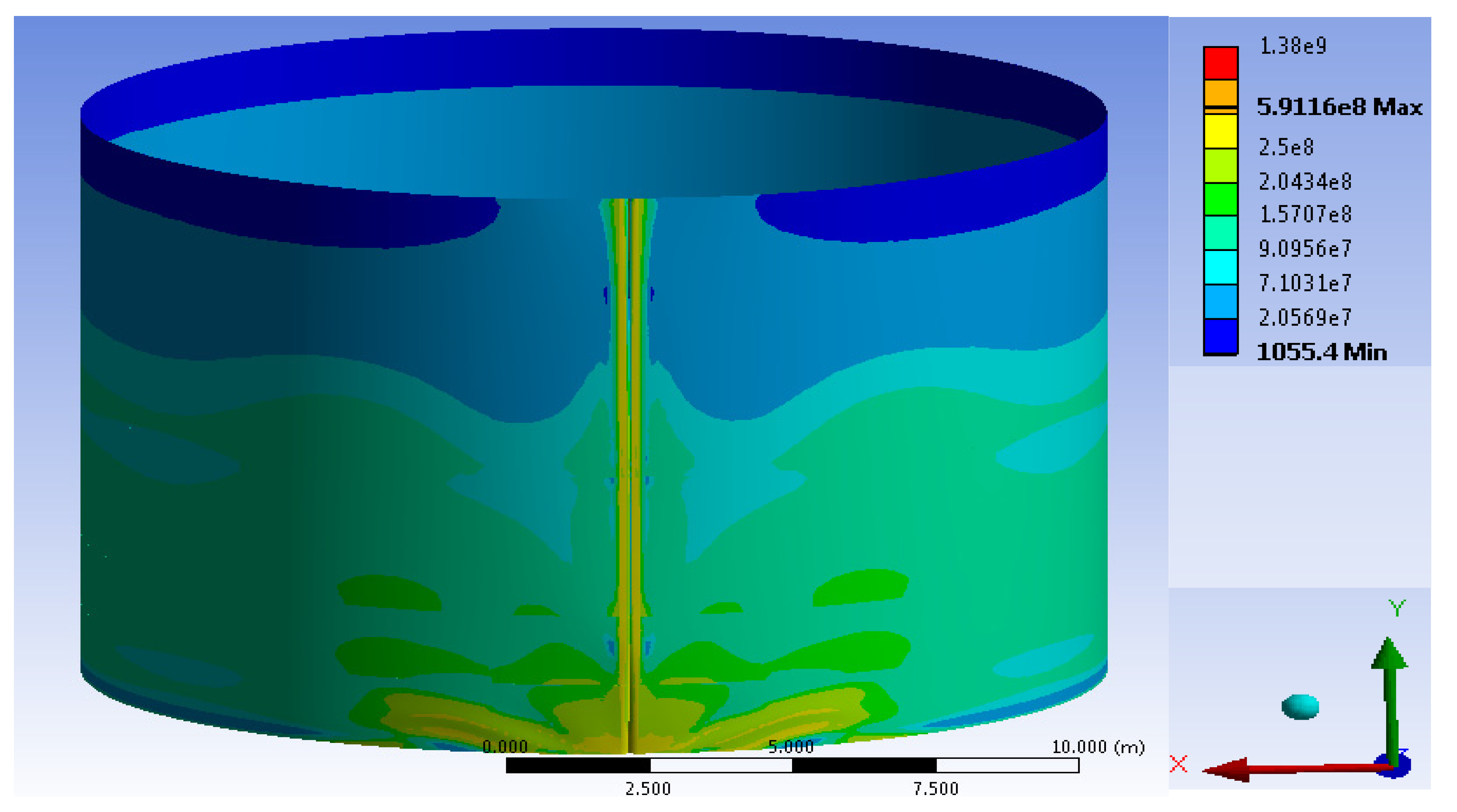
3. A Cylindrical Tank Wall Vertical Field Joint Zone’s Stress-Strain State Research Results
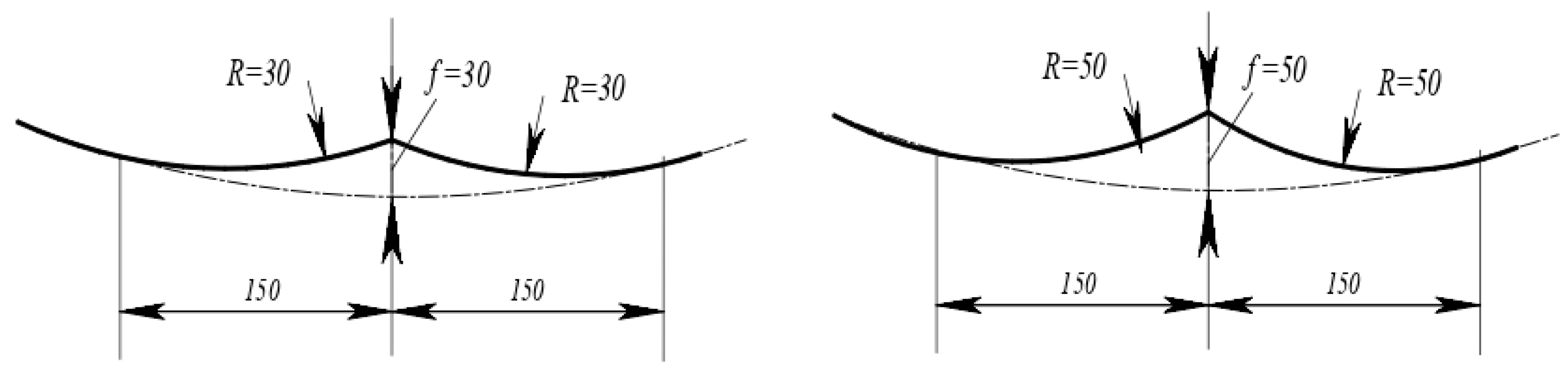
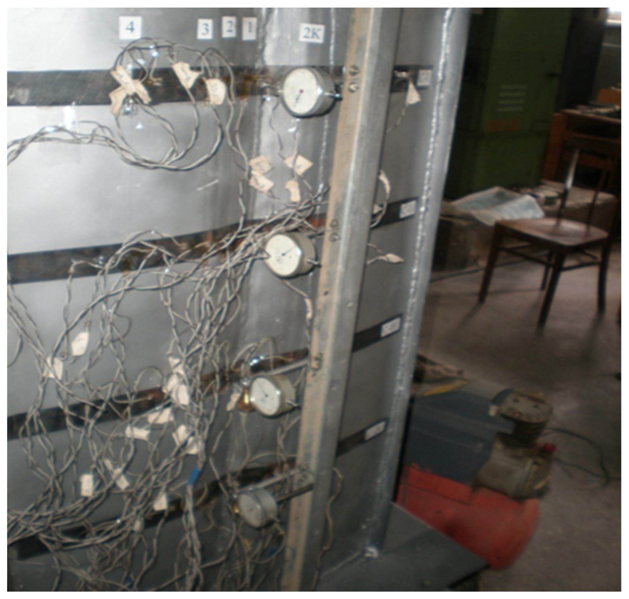
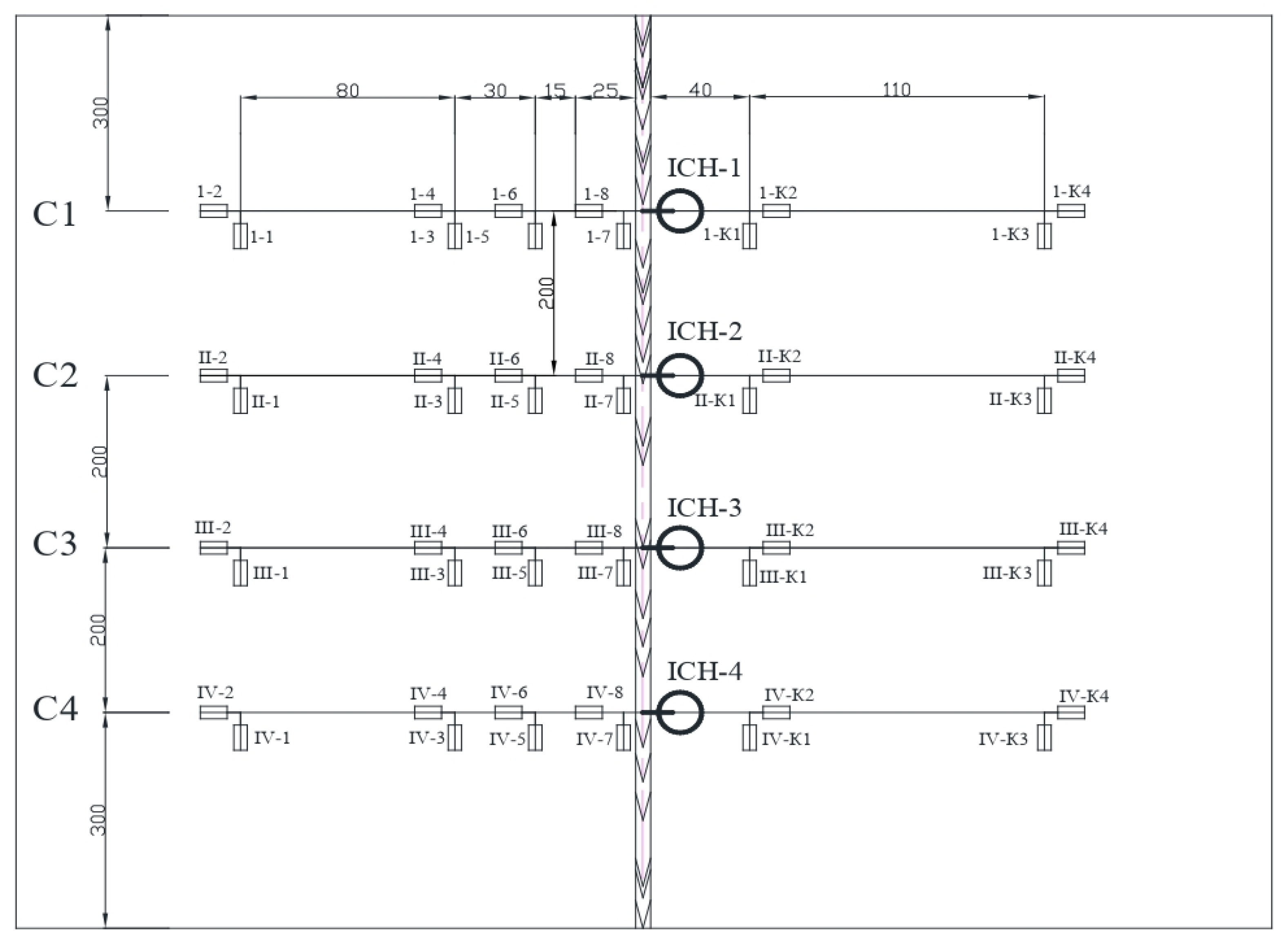
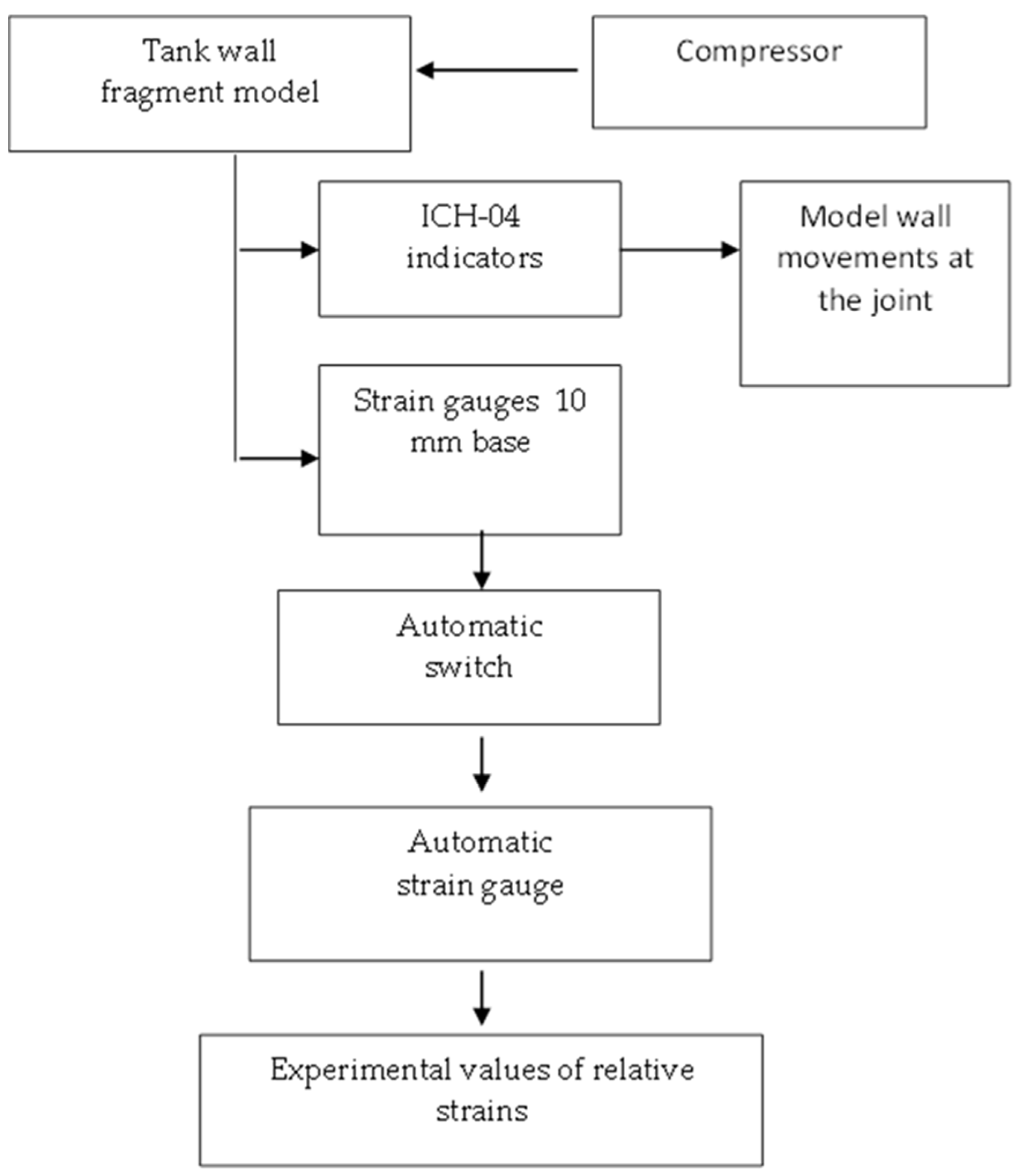
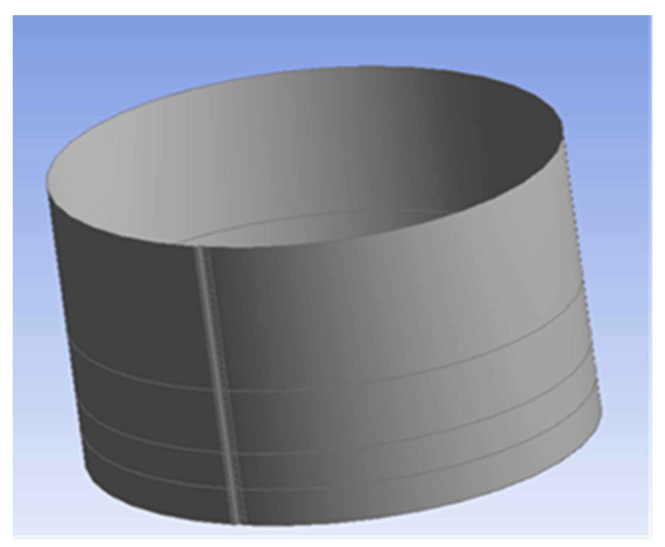
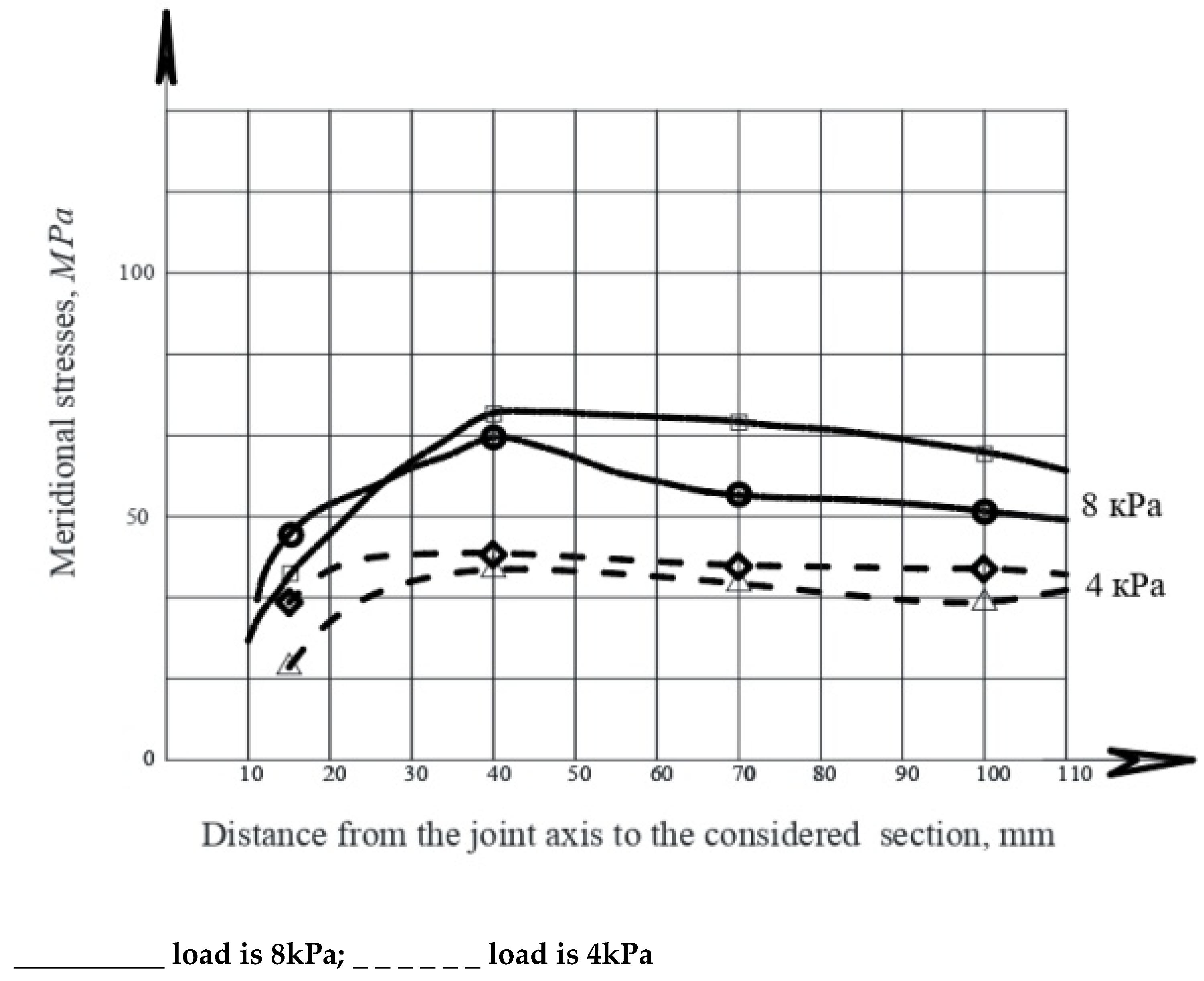
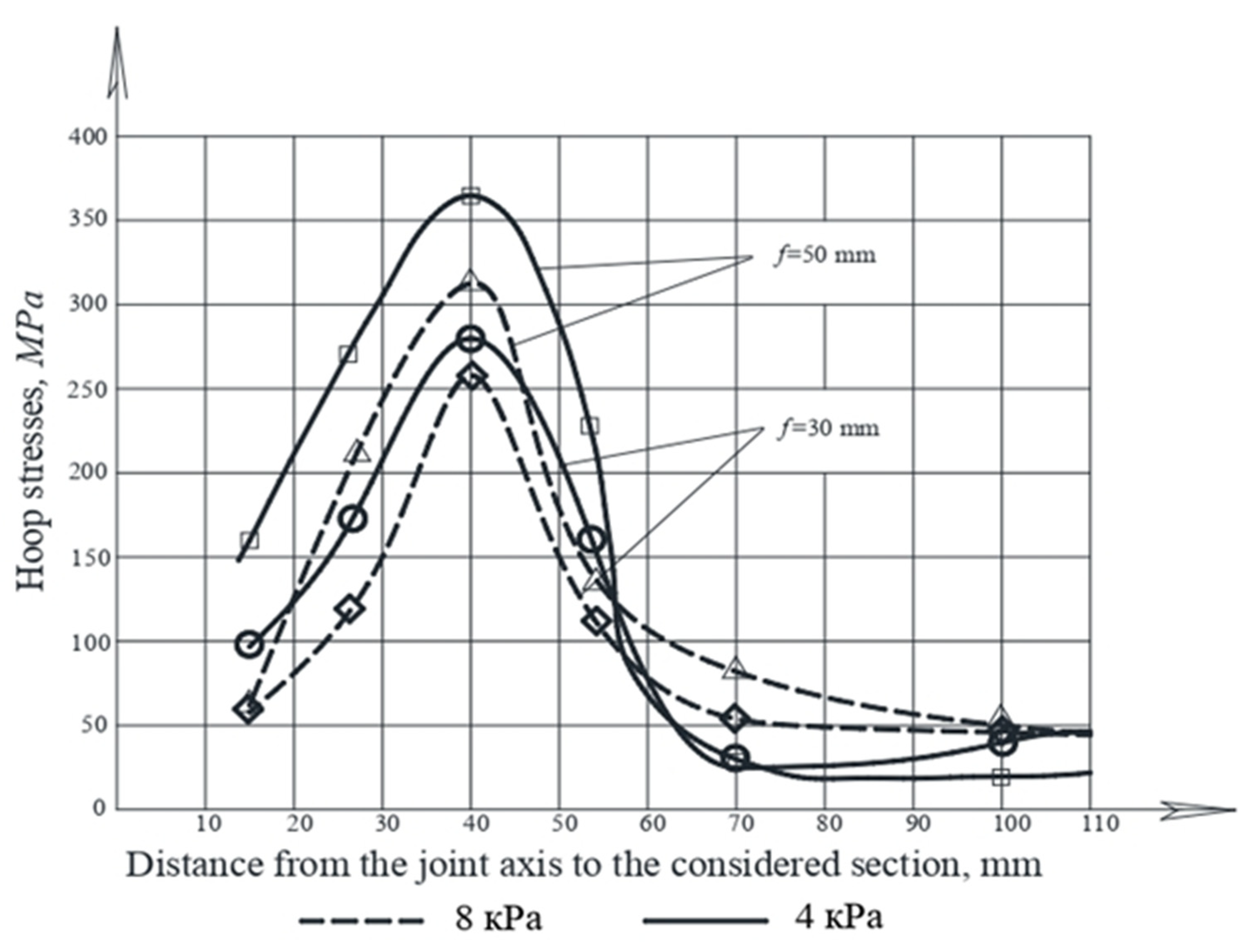
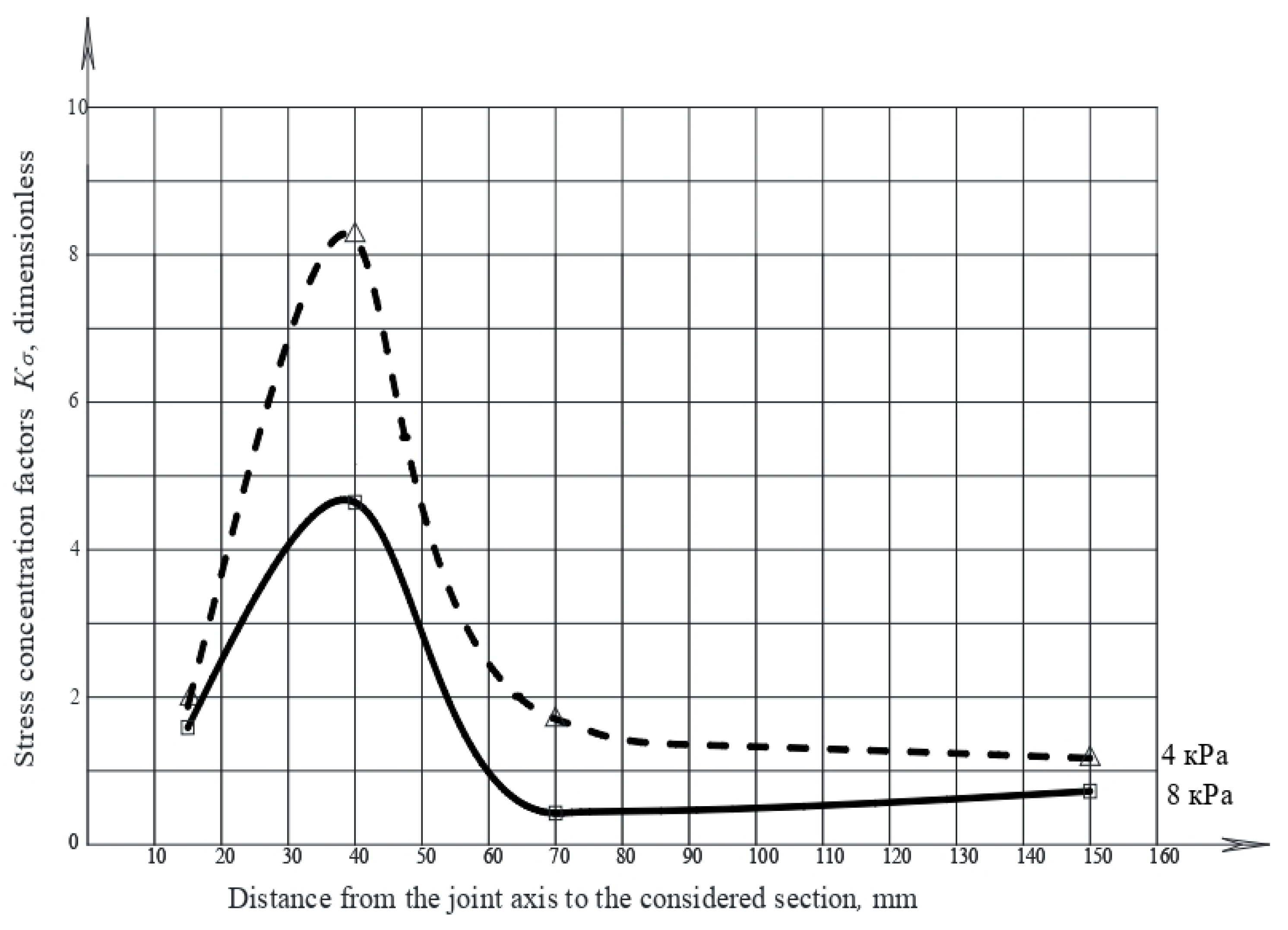
3.1. Experimental Research
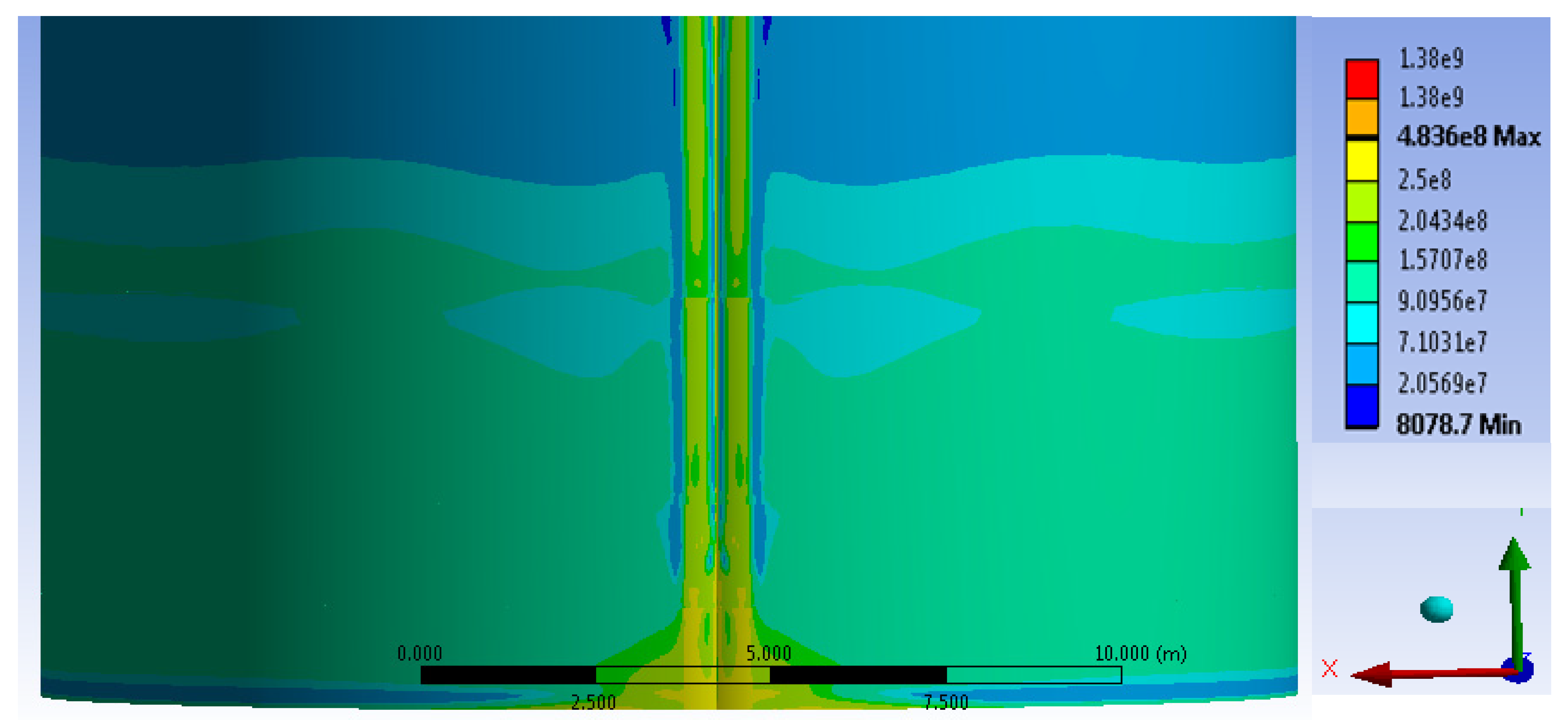
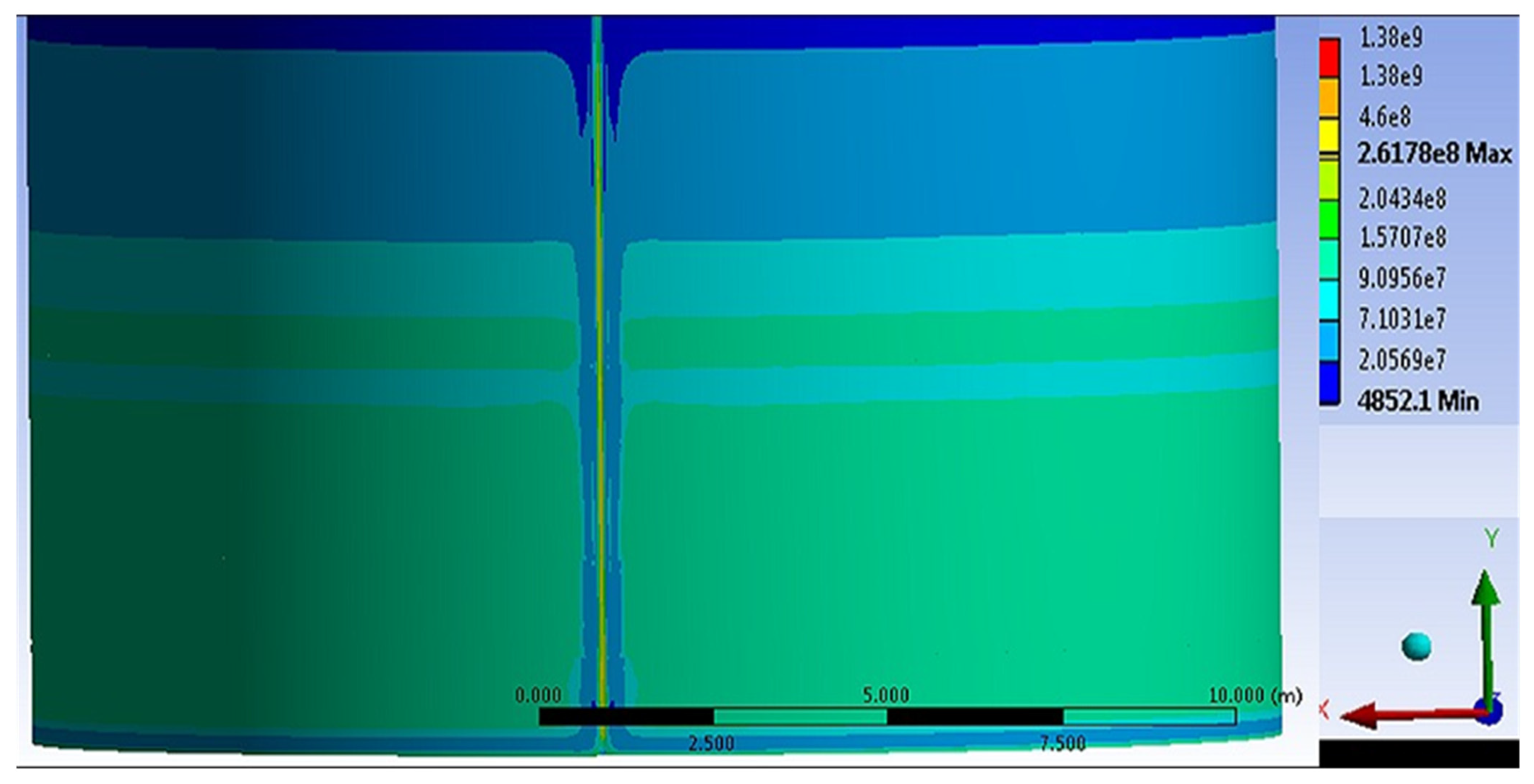
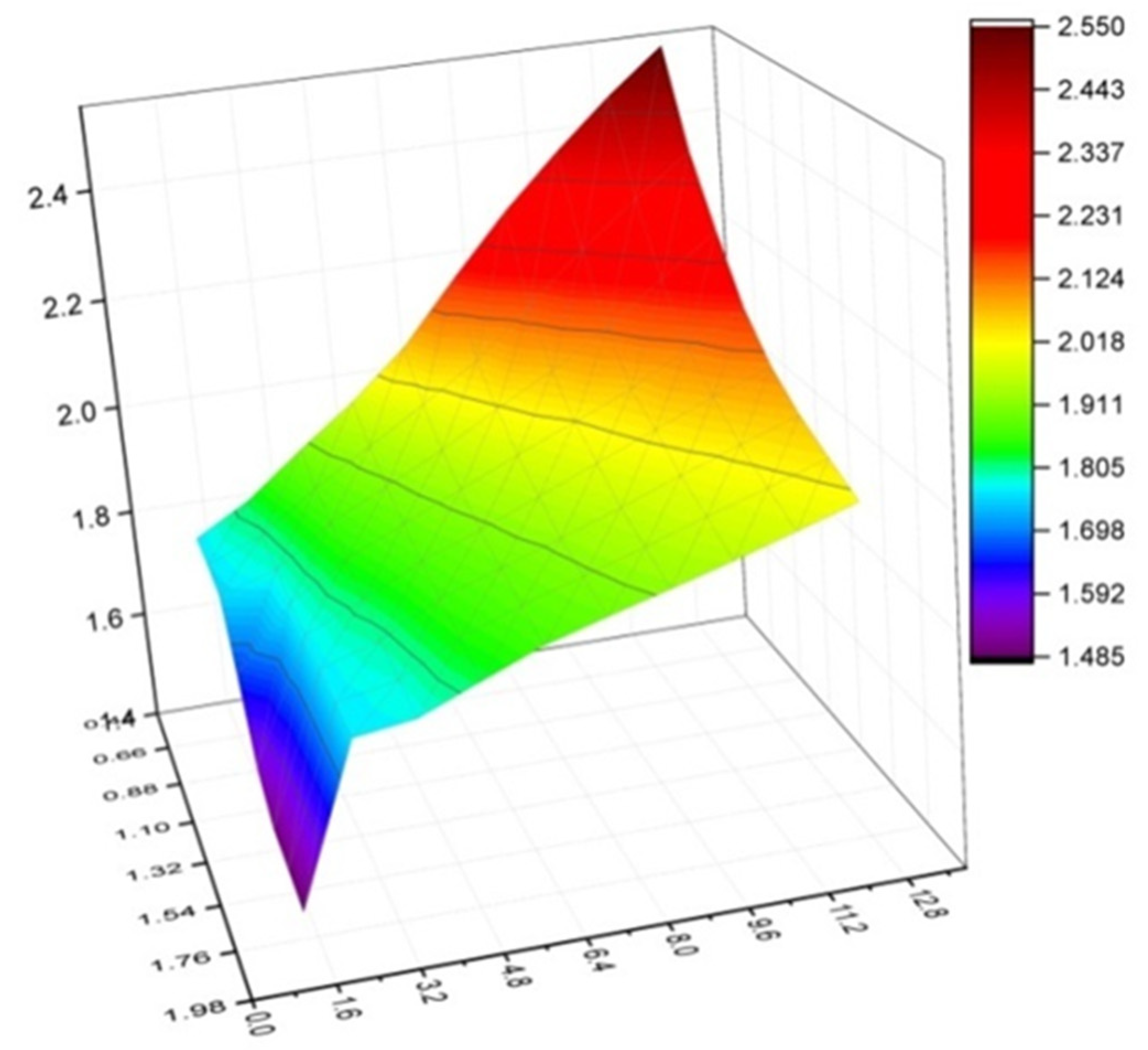
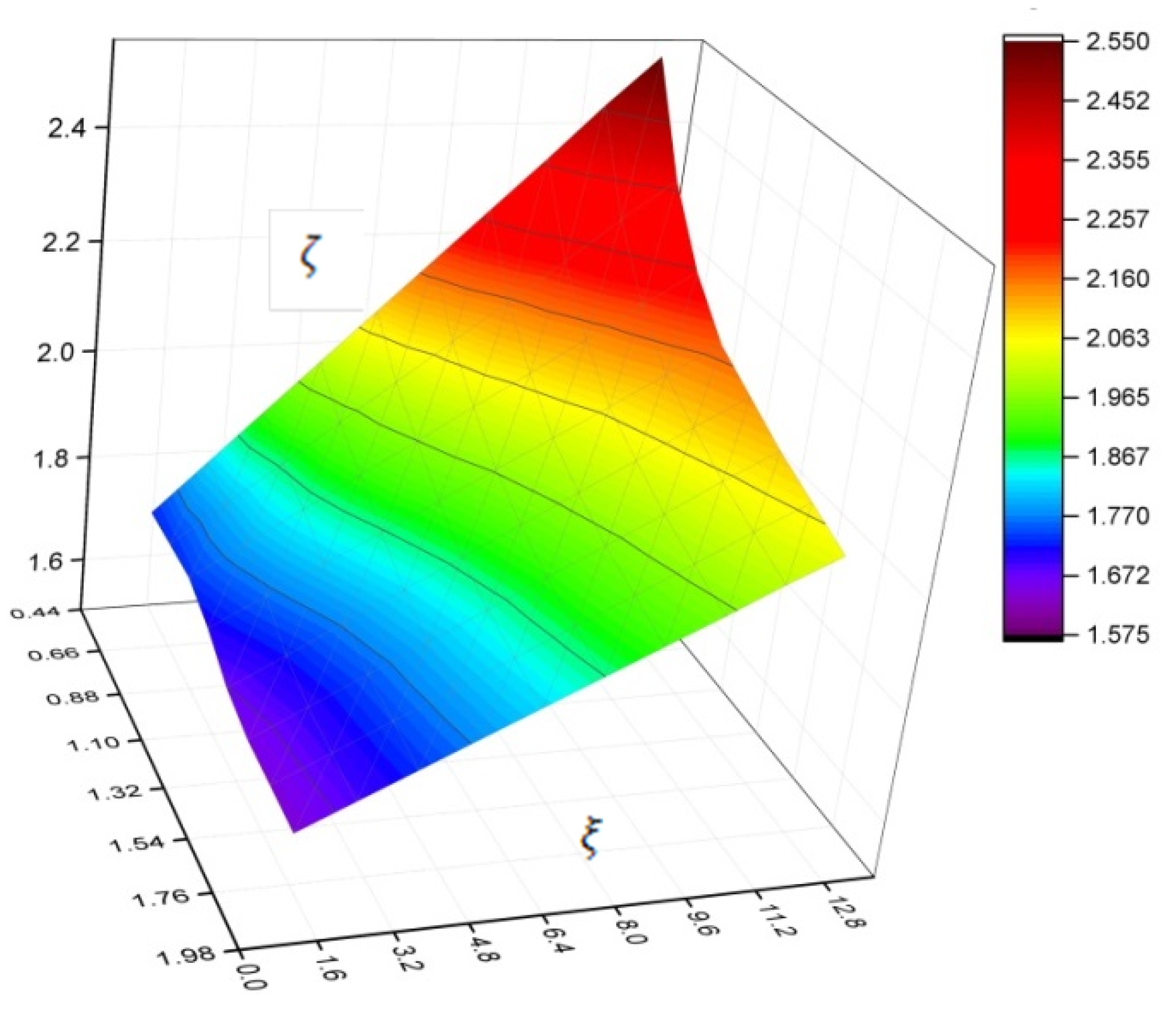
3.2. Theoretical Research
(9 − 68.83 ς + 224.56 ς2 − 408.82 ς3 + 454.87 ς4 − 317.13 ς5 + 135.45 ς6 − 32.44 ς7 + 3.339 ς8)ξ +
(9 − 73.80 ς + 257.28 ς2 − 496.76 ς3 + 581.33 ς4 − 422.87 ς5 + 187.123 ς6 − 46.156 ς7 + 4.86 ς8)ξ2 +
(9 − 67.80 ς + 217.80 ς2 − 390.58 ς3 + 428.48 ς4 − 294.90 ς5 + 124.51 ς6 − 29.514 ς7 + 3.009 ς8)ξ3 +
(9 − 68.87 ς + 224.86 ς2 − 409.63 ς3 + 456.04 ς4 − 318.12 ς5 + 135.94 ς6 − 32.57 ς7 + 3.353 ς8)ξ4
4. Discussion
5. Conclusions
- −
- By testing the tank wall fragment models with field joint imperfections, the field joint zone’s stress-strain state was assessed and the stress concentration dependence in the joint zone on the bend, zone width and tank wall thickness was established.
- −
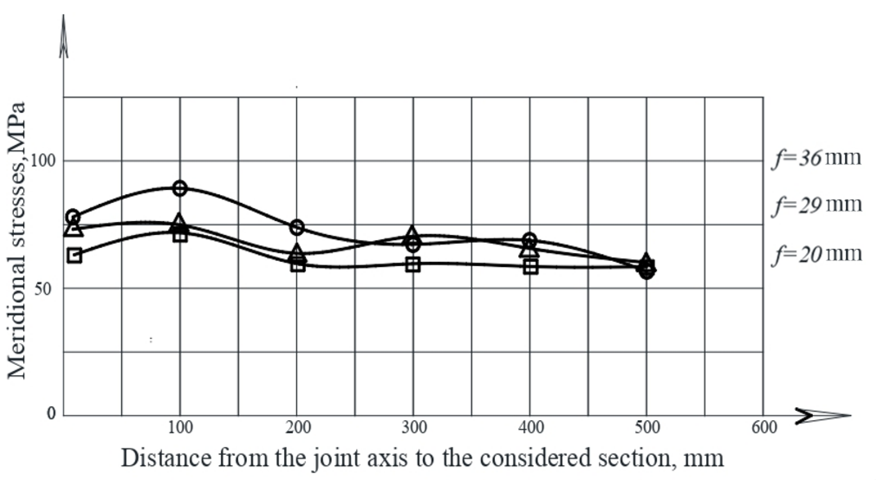
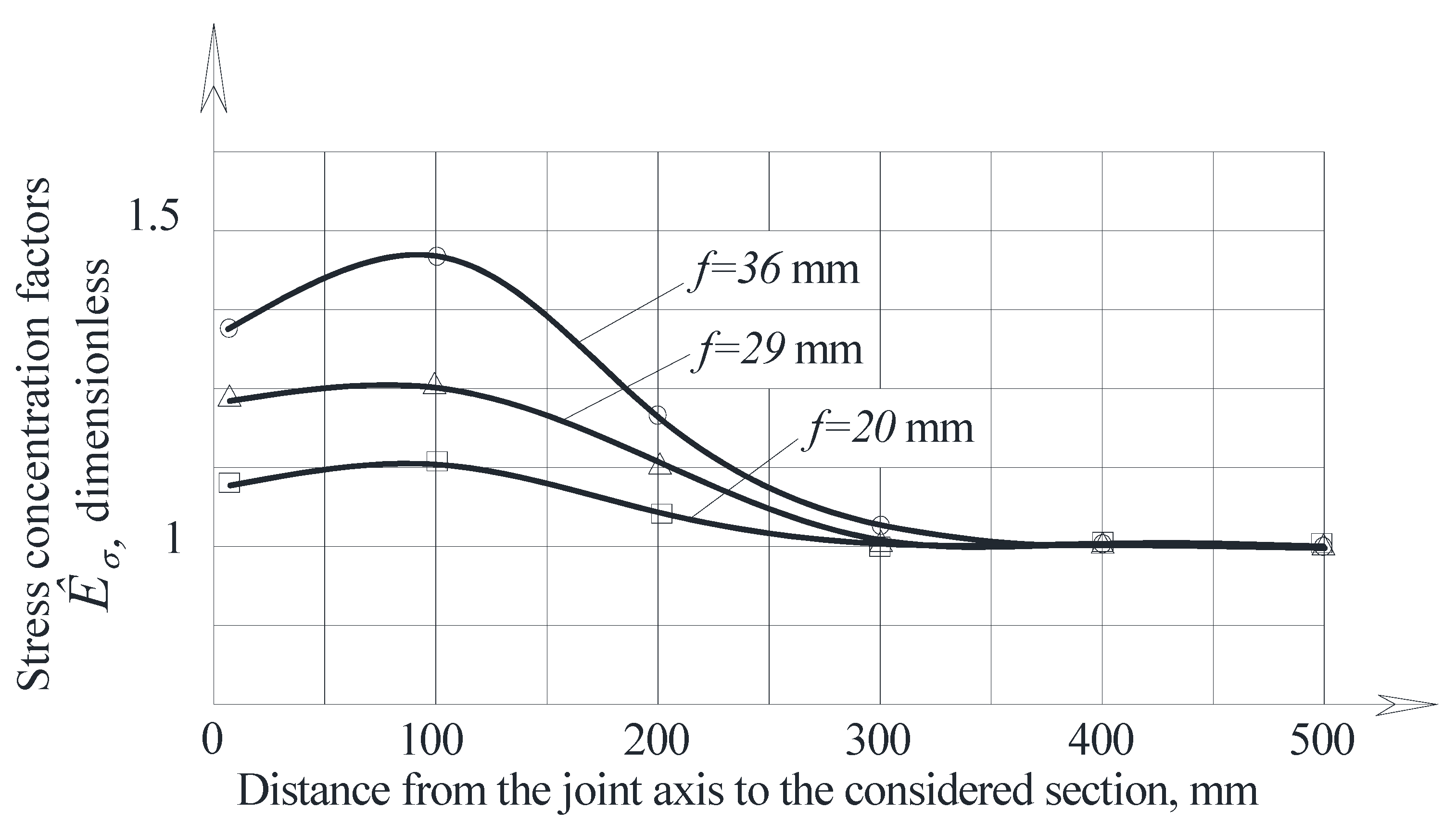
- The maximum hoop stresses in the joint zone in the model at the level of the main nominal stresses of 60.8 MPa with a 30 mm camber were 276 MPa and 358 MPa with a 50 mm camber. The maximum stress concentration in the joint zone was 4.54 for a 30 mm camber and 5.89 for a 50 mm camber.
- −
- The maximum meridional stresses in the joint zone in the model with 30 mm and 50 mm cambers at the nominal stress level of 32 MPa amounted to 67 MPa and 78 MPa, respectively.
- −
- Numerical analysis of tanks with joint imperfections estimated, in the ANSYS environment, the tank stress-strain state for various values of the joint bend parameters and and obtained the stress concentration factor dependence on the geometric dimensions of the tank wall imperfections, radius and thickness.
- −
- As a result of the calculations, the interpolation polynomial (5) was obtained, approximating the stress concentration factor Kσ, which can be used to assess the tank’s strength, durability and residual life, to normalize the limiting dimensions of the joint imperfection and establish the factor values, taking into account the features of the operation of structures at stress concentrations.
Author Contributions
Funding
Informed Consent Statement
Data Availability Statement
Conflicts of Interest
References
- Kudabayev, R.; Suleimenov, U.; Ristavletov, R.; Kasimov, I.; Kambarov, M.; Zhangabay, N.; Abshenov, K. Modeling the Thermal Regime of a Room in a Building with a Thermal Energy Storage Envelope. Math. Mod. Eng. Probl. 2022, 9, 351–358. [Google Scholar] [CrossRef]
- Zhangabay, N.; Abshenov, K.; Bakhbergen, S.; Zhakash, A.; Moldagaliyev, A. Evaluating the Effectiveness of Energy-Saving Retrofit Strategies for Residential Buildings. Inter. Rev. Civ. Eng. 2022, 13, 118–126. [Google Scholar] [CrossRef]
- Suleimenov, U.; Zhangabay, N.; Utelbayeva, A.; Mohamad, N.; Moldagaliyev, A.; Abshenov, K.; Buganova, S.; Daurbekova, S.; Ibragimova, Z.; Dosmakanbetova, A. Determining the features of oscillations in prestressed pipelines. East.-Eur. J. Enterp. Technol. 2021, 6, 85–92. [Google Scholar] [CrossRef]
- Tursunkululy, T.; Zhangabay, N.; Avramov, K.; Chernobryvko, M.; Suleimenov, U.; Utelbayeva, A.; Duissenbekov, B.; Aikozov, Y.; Dauitbek, B.; Abdimanat, Z. Strength analysis of prestressed vertical cylindrical steel oil tanks under operational and dynamic loads. East.-Eur. J. Enterp. Technol. 2022, 2, 14–21. [Google Scholar] [CrossRef]
- Available online: https://tebiz.ru/mi/analiz-rynka-nefteproduktov-v-kazakhstane (accessed on 25 May 2022).
- Mykhailo, H. Simulation of the stress-strain state of a cylindrical tank under the action of forced oscillations. Procedia Struct. Integr. 2022, 36, 79–86. [Google Scholar] [CrossRef]
- Marwan, M.; Muthana, M.; Al-Jumialya, A.; Al-Muhammadia, A.; Ismaila, S. Development of a New Method for Reducing the Loss of Light Hydrocarbons at Breather Valve of Oil Tanks. Energy Procedia 2017, 141, 471–478. [Google Scholar] [CrossRef]
- Hong, F.; Jiang, L.; Zhuo, Q.; Zhang, F.; Lu, X.; Ma, X.; Hao, J. Types of abnormal high-pressure gas reservoir in foreland basins of China. J. Nat. Gas Geosci. 2018, 3, 191–201. [Google Scholar] [CrossRef]
- Duissenbekov, B.; Tokmuratov, A.; Zhangabay, N.; Yerimbetov, B.; Aldiyarov, Z. Finite-difference equations of quasistatic motion of the shallow concrete shells in nonlinear setting. Curved Layer. Struct. 2020, 7, 48–55. [Google Scholar] [CrossRef]
- Borodin, K.; Zhangabay, N. Mechanical characteristics, as well as physical-and-chemical properties of the slag-filled concretes, and investigation of the predictive power of the metaheuristic approach. Curved Layer. Struct. 2019, 6, 236–244. [Google Scholar] [CrossRef]
- Utelbaeva, A.B.; Ermakhanov, M.N.; Zhanabai, N.; Utelbaev, B.; Mel’deshov, A. Hydrogenation of benzene in the presence of ruthenium on a modified montmorillonite support. Russ. J. Phys. Chem. 2013, 87, 1478–1481. [Google Scholar] [CrossRef]
- Filipov, V.; Prokhorov, V.; Argunov, S.; Buslaeva, I. The technical condition of the tanks for the storage of oil products of Yakutsknefteprodukt association. News Univ. Constr. 1993, 7, 13–16. Available online: https://cyberleninka.ru/article/n/tehnicheskaya-diagnostika-i-otsenka-ekspluatatsionnoy-nadezhnosti-rezervuarov-bolshogo-obema (accessed on 27 May 2022).
- Biletsky, S.; Golinko, V. Industrial production of oversized welded sheet structures. Nauk. Dumka. 1983, 272. Available online: https://search.rsl.ru/ru/record/01001165555 (accessed on 25 May 2022).
- Ivantsova, S.; Rakhmanin, A.; Tarasenko, M.; Silnitsky, P. The concept of risk analysis of tank structures. Qual. Manag. Oil Gas Complex 2011, 3, 31–35. [Google Scholar]
- Mansurova, S.M.; Tlyasheva, R.R. Evaluation of the stress-strain state of a steel cylindrical tank, taking into account operational loads. Oil Gas Bus. Electron. Sci. J. 2014, 1, 2328–2334. [Google Scholar]
- Suleimenov, U.; Zhangabay, N.; Utelbayeva, A.; Masrah, A.; Dosmakanbetova, A.; Abshenov, K.; Buganova, S.; Moldagaliyev, A.; Imanaliyev, K.; Duissenbekov, B. Estimation of the strength of vertical cylindrical liquid storage tanks with dents in the wall. East.-Eur. J. Enterp. Technol. 2022, 7, 6–20. [Google Scholar] [CrossRef]
- Zhangabay, N.; Sapargaliyeva, B.; Utelbayeva, A.; Kolesnikov, A.; Aldiyarov, Z.; Dossybekov, S.; Esimov, E.; Duissenbekov, B.; Fediuk, R.; Vatin, N.I.; et al. Experimental Analysis of the Stress State of a Prestressed Cylindrical Shell with Various Structural Parameters. Materials 2022, 15, 4996. [Google Scholar] [CrossRef]
- Li, Z.; Song, B.; Li, D. Safety Risk Recognition Method Based on Abnormal Scenarios. Buildings 2022, 12, 562. [Google Scholar] [CrossRef]
- Thongchom, C.; Jearsiripongkul, T.; Refahati, N.; Roudgar Saffari, P.; Roodgar Saffari, P.; Sirimontree, S.; Keawsawasvong, S. Sound Transmission Loss of a Honeycomb Sandwich Cylindrical Shell with Functionally Graded Porous Layers. Buildings 2022, 12, 151. [Google Scholar] [CrossRef]
- Kou, S.; Zhang, X.; Li, W.; Song, C. Dynamic Response Parameter Analysis of Steel Frame Joints under Blast Loading. Buildings 2022, 12, 433. [Google Scholar] [CrossRef]
- Wang, J.; Kusunoki, K. Study on the Flexural Strength of Interior Thick Wall-Thick Slab Joints Subjected to Lateral Force Using Finite-Element Analysis. Buildings 2022, 12, 535. [Google Scholar] [CrossRef]
- Fan, Y.; Hunt, J.; Wang, Q.; Yin, S.; Li, Y. Water tank modelling of variations in inversion breakup over a circular city. Build. Environ. 2019, 164, 106342. [Google Scholar] [CrossRef]
- Martynenko, G.; Avramov, K.; Martynenko, V.; Chernobryvko, M.; Tonkonozhenko, A.; Kozharin, V. Numerical simulation of warhead transportation. Def. Technol. 2021, 17, 478–494. [Google Scholar] [CrossRef]
- Wang, Z.; Hu, K.; Zhao, Y. Doom-roof steel tanks under external explosion: Dynamic responses and anti-explosion measures. J. Constr. Steel Res. 2022, 190, 107118. [Google Scholar] [CrossRef]
- Rastgar, M.; Showkati, H. Buckling behavior of cylindrical steel tanks with concavity of vertical weld line imperfection. J. Constr. Steel Res. 2018, 145, 289–299. [Google Scholar] [CrossRef]
- Fatma, M.; Aydın, K.; Mahyar, M.; Mahmut, K.; Cüneyt, A. Experimental analysis of the effect of dent variation on the buckling capacity of thin-walled cylindrical shells. Thin-Walled Struct. 2019, 143, 106259. [Google Scholar] [CrossRef]
- Coramik, M.; Ege, Y. Discontinuity inspection in pipelines: A comparison review. Measurement 2017, 111, 359–373. [Google Scholar] [CrossRef]
- Bannikov, R.; Smetannikov, O.; Trufanov, N.A. Method for calculating the amplitude of local conditional elastic stresses on the section of the tank wall with a shape defect in the form of dents. Bull. Samara State Tech. Univ. 2014, 2, 79–86. Available online: http://vestnik-teh.samgtu.ru/sites/vestnik-teh.samgtu.ru/files/auto/42_4_mashinostroenie_2014.pdf (accessed on 20 May 2022).
- Dmitrieva, A.S.; Lyagova, A.A. Problems of assessing the technical condition of steel tanks with the “Dent” defect. In Science and Youth in the XXI Century, Proceedings of 2nd All-Russian Scientific and Practical Conference; Omsk State Technical University: Omsk, Russia, 2016; pp. 138–142. Available online: https://www.elibrary.ru/item.asp?id=28085497 (accessed on 25 May 2022).
- Mariusz, M.; Michal, P.; Janusz, S.; Krzyszt, T. Corrosion Durability Estimation for Steel Shell of a Tank Used to Store Liquid Fuels. Procedia Eng. 2017, 172, 723–730. [Google Scholar] [CrossRef]
- Song, Z.; Komvopoulos, K. Contact mechanics analysis of oscillatory sliding of a rigid fractal surface against an elastic-plastic half-space. Philos. Mag. 2014, 94, 3215–3233. [Google Scholar] [CrossRef]
- Hagihara, S.; Tsunori, M.; Ikeda, T.; Miyazaki, N. Application of meshfree method to elastic-plastic fracture mechanics parameter analysis. Comput. Model. Eng. Sci. 2007, 17, 63–72. [Google Scholar] [CrossRef]
- Sun, J. Hard particle force in a soft fracture. Sci. Rep. 2019, 9, 3065. [Google Scholar] [CrossRef] [PubMed]
- Zhang, Y.M.; Tan, T.K.; Xiao, Z.; Zhang, W.G.; Ariffin, M.Z. Failure Assessment on Offshore Girth Welded Pipelines due to Corrosion Defects. Fatigue Fract. Eng. Mater. Struct. 2016, 39, 453–466. [Google Scholar] [CrossRef]
- Yi, D.; Sridhar, I.; Xiao, Z.; Kumar, S. Fracture capacity of girth welded pipelines with 3D surface cracks subjected to biaxial loading conditions. Int. J. Press. Vessel. Pip. 2012, 92, 115–126. [Google Scholar] [CrossRef]
- Kolesov, A.I.; Ageeva, M.A. Residual resource of steel tanks for chemistry and petrochemistry that have worked out their standard operating life. Bull. MSCU 2011, 1, 388–391. [Google Scholar]
- TP-704-1-167-84. Steel Vertical Cylindrical Tank for Oil and Oil Products with a Volume of 3000 m3. Album I. Metal Tank Structures. Available online: https://meganorm.ru/Data2/1/4293833/4293833208.pdf (accessed on 28 May 2022).
- GOST 27069-86. Metallic Ferroalloys, Chromium and Manganese. Methods for Determining Carbon. Available online: https://docs.cntd.ru/document/1200008986 (accessed on 25 May 2022).
- GOST 1497-84. Metals. Tensile Test Methods. Available online: https://docs.cntd.ru/document/1200004888 (accessed on 25 May 2022).
- Volokitina, I.; Siziakova, E.; Fediuk, R.; Kolesnikov, A. Development of a Thermomechanical Treatment Mode for Stainless-Steel Rings. Materials 2022, 15, 4930. [Google Scholar] [CrossRef] [PubMed]
- Kolesnikov, A.S. Kinetic Investigations into the Distillation of Nonferrous Metals during Complex Processing of Waste of Metallurgical Industry. Rus. J. Non-Ferr. Met. 2015, 56, 1–5. [Google Scholar] [CrossRef]
- Volokitin, A.; Naizabekov, A.; Volokitina, I.; Kolesnikov, A. Changes in microstructure and properties of austenitic steel aisi 316 during high-pressure torsion. J. Chem. Technol. Metall. 2022, 57, 809–815. [Google Scholar]
- Kuatbay, Y.; Nurumgaliyev, A.; Shabanov, Y.; Zayakin, O.; Gabdullin, S.; Zhuniskaliyev, T. Melting of high-carbon ferrochrome using coal of the saryadyr deposit. Metalurgija 2022, 61, 367–370. [Google Scholar]
- Kolesnikov, A.S. Thermodynamic simulation of silicon and iron reduction and zinc and lead distillation in zincoligonite ore-carbon systems. Russ. J. Non-Ferr. Met. 2014, 55, 513–518. [Google Scholar] [CrossRef]
- Boikov, A.; Payor, V.; Savelev, R.; Kolesnikov, A. Synthetic data generation for steel defect detection and classification using deep learning. Symmetry 2021, 13, 1176. [Google Scholar] [CrossRef]
- Kolesnikov, A.S.; Sergeeva, I.V.; Botabaev, N.E.; Al’Zhanova, A.Z.; Ashirbaev, K.A. Thermodynamic simulation of chemical and phase transformations in the system of oxidized manganese ore—Carbon. Izv. Ferr. Metall. 2017, 60, 759–765. [Google Scholar] [CrossRef]
- Volokitina, I.; Kolesnikov, A.; Fediuk, R.; Klyuev, S.; Sabitov, L.; Volokitin, A.; Zhuniskaliyev, T.; Kelamanov, B.; Yessengalie, V.D.; Yerzhanov, A.; et al. Study of the Properties of Antifriction Rings under Severe Plastic Deformation. Materials 2022, 15, 2584. [Google Scholar] [CrossRef] [PubMed]
- Kolesnikov, A.; Fediuk, R.; Amran, M.; Klyuev, S.; Klyuev, A.; Volokitina, I.; Naukenova, A.; Shapalov, S.; Utelbayeva, A.; Kolesnikova, O.; et al. Modeling of Non-Ferrous Metallurgy Waste Disposal with the Production of Iron Silicides and Zinc Distillation. Materials 2022, 15, 2542. [Google Scholar] [CrossRef] [PubMed]
- Vasilyeva, N.; Fedorova, E.; Kolesnikov, A. Big Data as a Tool for Building a Predictive Model of Mill Roll Wear. Symmetry 2021, 13, 859. [Google Scholar] [CrossRef]
- Rensky, A.B.; Baranov, D.S. Strain Measurement of Building Structures and Materials; Stroyizdat: Moscow, Russia, 1977; 239p, Available online: https://e-catalog.nlb.by/Record/BY-NLB-rr29377930000 (accessed on 25 May 2022).
- Kolesnikov, A.; Fediuk, R.; Kolesnikova, O.; Zhanikulov, N.; Zhakipbayev, B.; Kuraev, R.; Akhmetova, E.; Shal, A. Processing of Waste from Enrichment with the Production of Cement Clinker and the Extraction of Zinc. Materials 2022, 15, 324. [Google Scholar] [CrossRef]
- Zhakipbaev, B.Y.; Zhanikulov, N.N.; Kuraev, R.M.; Shal, A.L. Review of technogenic waste and methods of its processing for the purpose of complex utilization of tailings from the enrichment of non-ferrous metal ores as a component of the raw material mixture in the production of cement clinker. Rasayan J. Chem. 2021, 14, 997–1005. [Google Scholar] [CrossRef]
- Serikbaev, B.E.; Zolkin, A.L.; Kenzhibaeva, G.S. Processing of Non-Ferrous Metallurgy Waste Slag for its Complex Recovery as a Secondary Mineral Raw Material. Refract. Ind. Ceram. 2021, 62, 375–380. [Google Scholar] [CrossRef]
- Kolesnikov, A.S.; Zhanikulov, N.N.; Zhakipbayev, B.Y.; Kolesnikova, O.G.; Kuraev, R.M. Thermodynamic modeling of the synthesis of the main minerals of cement clinker from technogenic raw materials. Kompleksnoe Ispol’zovanie Mineral’nogo Syr’a. (Complex Use Miner. Resour.) 2021, 318, 24–34. [Google Scholar] [CrossRef]
- Zhanikulov, N.N.; Khudyakova, T.M.; Taimasov, B.T. Receiving portland cement from technogenic raw materials of South Kazakhstan portlandcement. Eurasian Chem. Technol. J. 2019, 21, 334–340. [Google Scholar] [CrossRef]
- GOST 50779.21-2004. Statistical Methods. Rules for Determining and Methods for Calculating Statistical Characteristics from Sample Data. Part 1. Normal Distribution. Available online: https://docs.cntd.ru/document/1200035333 (accessed on 25 May 2022).
- Makul, N.; Fediuk, R.; Amran, M.; Zeyad, A.M.; Murali, G.; Vatin, N.; Klyuev, S.; Ozbakkaloglu, T.; Vasilev, Y. Use of Recycled Concrete Aggregates in Production of Green Cement-Based Concrete Composites: A Review. Crystals 2021, 11, 232. [Google Scholar] [CrossRef]
- Fediuk, R.S.; Yushin, A.M. The use of fly ash the thermal power plants in the construction. IOP Conf. Ser. Mater. Sci. Eng. 2015, 93, 012070. [Google Scholar] [CrossRef]
- Abid, S.R.; Murali, G.; Amran, M.; Vatin, N.; Fediuk, R.; Karelina, M. Evaluation of Mode II Fracture Toughness of Hybrid Fibrous Geopolymer Composites. Materials 2021, 14, 349. [Google Scholar] [CrossRef] [PubMed]
- Zhangabay, N.; Sapargaliyeva, B.; Suleimenov, U.; Abshenov, K.; Utelbayeva, A.; Kolesnikov, A.; Baibolov, K.; Fediuk, R.; Arinova, D.; Duissenbekov, B.; et al. Analysis of Stress-Strain State for a Cylindrical Tank Wall Defected Zone. Materials 2022, 15, 5732. [Google Scholar] [CrossRef] [PubMed]
- Suleimenov, U.; Zhangabay, N.; Abshenov, K.; Utelbayeva, A.; Imanaliyev, K.; Mussayeva, S.; Moldagaliyev, A.; Yermakhanov, M.; Raikhanova, G. Estimating the stressed-strained state of the vertical mounting joint of the cylindrical tank wall taking into consideration imperfections. East.-Eur. J. Enterp. Technol. 2022, 3, 14–21. [Google Scholar] [CrossRef]


| Steel | Mechanical Properties | Мn | Si | S | P | Cr | Ni | Cu | |
|---|---|---|---|---|---|---|---|---|---|
| Yield Strength, MPa | Breaking Strength, MPa | ||||||||
| VStp | 240–245 | 370–480 | ≤0.65 | 0.15–0.30 | 0.050 | 0.040 | ≤0.30 | ≤0.30 | 0.30 |
| 1.25 | 2.50 | 3.75 | 5.00 | 6.25 | 7.50 | 8.75 | 10.00 | 11.25 | 12.50 | |
|---|---|---|---|---|---|---|---|---|---|---|
| 1.87 | 1.487 | 1.761 | 1.775 | 1.818 | 1.859 | 1.889 | 1.917 | 1.946 | 1.977 | 2.009 |
| 1.68 | 1.495 | 1.763 | 1.783 | 1.836 | 1.873 | 1.905 | 1.937 | 1.971 | 2.002 | 2.037 |
| 1.49 | 1.502 | 1.765 | 1.796 | 1.851 | 1.885 | 1.920 | 1.956 | 1.994 | 2.030 | 2.066 |
| 1.31 | 1.550 | 1.769 | 1.815 | 1.865 | 1.903 | 1.945 | 1.987 | 2.030 | 2.071 | 2.108 |
| 1.12 | 1.661 | 1.775 | 1.836 | 1.883 | 1.928 | 1.973 | 2.016 | 2.059 | 2.116 | 2.172 |
| 0.93 | 1.753 | 1.784 | 1.855 | 1.904 | 1.954 | 2.014 | 2.066 | 2.128 | 2.201 | 2.273 |
| 0.75 | 1.761 | 1.800 | 1.872 | 1.933 | 1.995 | 2.061 | 2.146 | 2.234 | 2.311 | 2.384 |
| 0.56 | 1.762 | 1.820 | 1.899 | 1.974 | 2.062 | 2.176 | 2.284 | 2.380 | 2.468 | 2.546 |
Publisher’s Note: MDPI stays neutral with regard to jurisdictional claims in published maps and institutional affiliations. |
© 2022 by the authors. Licensee MDPI, Basel, Switzerland. This article is an open access article distributed under the terms and conditions of the Creative Commons Attribution (CC BY) license (https://creativecommons.org/licenses/by/4.0/).
Share and Cite
Zhangabay, N.; Suleimenov, U.; Utelbayeva, A.; Kolesnikov, A.; Baibolov, K.; Imanaliyev, K.; Moldagaliyev, A.; Karshyga, G.; Duissenbekov, B.; Fediuk, R.; et al. Analysis of a Stress-Strain State of a Cylindrical Tank Wall Vertical Field Joint Zone. Buildings 2022, 12, 1445. https://doi.org/10.3390/buildings12091445
Zhangabay N, Suleimenov U, Utelbayeva A, Kolesnikov A, Baibolov K, Imanaliyev K, Moldagaliyev A, Karshyga G, Duissenbekov B, Fediuk R, et al. Analysis of a Stress-Strain State of a Cylindrical Tank Wall Vertical Field Joint Zone. Buildings. 2022; 12(9):1445. https://doi.org/10.3390/buildings12091445
Chicago/Turabian StyleZhangabay, Nurlan, Ulanbator Suleimenov, Akmaral Utelbayeva, Alexandr Kolesnikov, Kanat Baibolov, Kuanysh Imanaliyev, Arman Moldagaliyev, Galymzhan Karshyga, Bolat Duissenbekov, Roman Fediuk, and et al. 2022. "Analysis of a Stress-Strain State of a Cylindrical Tank Wall Vertical Field Joint Zone" Buildings 12, no. 9: 1445. https://doi.org/10.3390/buildings12091445