
Transfer Matrix Method for Calculating the Transverse Load Distribution of Articulated Slab Bridges

1
School of Civil Engineering, Southeast University, Nanjing 211189, China
2
Key Laboratory of Concrete and Prestressed Concrete Structures of Ministry of Education, Southeast University, Nanjing 211189, China
3
Department of Civil and Environmental Engineering, Universitat Politècnica de Catalunya, BarcelonaTECH, 08034 Barcelona, Spain
*
Author to whom correspondence should be addressed.
Buildings 2022, 12(10), 1610; https://doi.org/10.3390/buildings12101610
Submission received: 27 August 2022
/
Revised: 11 September 2022
/
Accepted: 26 September 2022
/
Published: 5 October 2022
(This article belongs to the Topic Advances on Structural Engineering, 2nd Volume)
Abstract
:Articulated slab bridges have been widely used by transportation administration for short-to-medium span bridges because of their good economy, convenient construction, and environmental advantages, while the presence of shear keys increases the complexity of structural behavior. Developing more reasonable analysis approaches of quick assessment, pre-design, and hand calculations for the articulated slab bridges is a challenge because of the peculiar shear key mechanism. This paper is devoted to presenting a recursive algorithm, based on the force equilibrium conditions of each individual slab, thus resulting in simultaneous equations of the transfer matrix method (TMM). In this procedure, the state vector is an array composed of vertical displacement, shear force, unit constant; and the transfer matrix contains the bending and torsional stiffness parameters of simply supported slabs. Then, the influence line of transverse load distribution (TLD) is calculated for each slab by introducing boundary conditions. To validate and verify the efficiency of the TMM algorithm, a transversely prefabricated void slab bridge with a span of 20 m is considered as a case study. The traditional force (FM) and finite element (FEM) methods are used for comparison and validation. It is demonstrated that the TMM can provide good results with higher algorithm efficiency by exempting the modeling tasks in FM and FEM and capture variations in TLD along the bridge’s span. In addition, the influence of the span length and relative stiffness coefficient of slabs on the TLD of articulated slab bridges are analyzed from the parametric analysis.
1. Introduction
An articulated slab bridge consists of a number of discrete slab units laid side-by-side, with in-situ casted shear keys to form a continuous deck. This type of deck is competitive for short-to-medium span bridges because of its good economy, low deck height, and ease of prefabrication. A crucial point in such a deck is the mechanism by which the beams are keyed together. One relevant characteristic of the shear key is an absence of reinforcement crossing the key. Therefore, the flexural strength of the shear key is negligible and transfers only vertical shear forces between adjacent slabs under vehicle loads.
In view of the unique structural feature invoked by transverse connections, numerous methods of analysis for such deck structures have been investigated [1,2,3]. So far, the concepts of influence line of transverse load distribution (TLD) are broadly accepted to facilitate the analysis of bridge decks under vehicular live load. A common practice is, thus, to use load distribution factors, in order to isolate a single slab from the rest of the superstructure system, thus transforming a complex space analysis into a simple plane problem [4].
Even though many TLD algorithms have been proposed, some major codes still use fitted empirical formulas, which suggests that more concise and applicable methods with a theoretical basis are still in need. Regarding the empirical equations for TLD in AASHTO LRFD bridge design specifications [5], Zokaie [6] expatiated the fitting process and their application range. In the Canadian Highway Bridge Design Code (CHBDC) [7], the live load acting on the bridge was assumed to be distributed equally to the individual girders and then multiplied by an amplification coefficient. The amplification coefficient was obtained from extensive parametric analyses, based on the orthotropic plate theory, according to the structural characteristics of the bridge. On the other hand, the Eurocode [8], does not explicitly include the concept of the TLD of bridges as an analysis method, and the loads borne by each girder are generally obtained by the analysis of the grillage model.
In addition to the codified methods, efforts for better algorithms have never stopped. Semendary et al. [9] investigated the distribution coefficients of the live load bending moments of a concrete box-girder bridge with cast-in-place, ultra-high-performance concrete (UHPC) shear key connections. They concluded that the results of the formulae in the AASHTO were conservative through field load tests and 3D finite element model analysis. Liu et al. [10] argued that the slab bridges connected by longitudinal joints only transversely transfer shear forces. They introduced the damage factor and studied the effect of joint damage on TLD by heuristic methods, based on the artificial bee colony algorithm. Zhao et al. [11] conducted field load tests on a skew void slab bridge, established a finite element model, and analyzed the effects of span length, skew angle, and deck slab thickness on the TLD coefficient. Whelchel et al. [12] investigated the effects of joint damage, joint failure, and deck thickness on live load distribution coefficients through field load tests and compared the calculation results in the AASHTO for different periods. Ndong et al. [13] proposed the use of refined analysis methods to potentially improve the load ratings of concrete T-beam bridges by obtaining a decrease in TLD factors. Aloisio et al. [14] presented a mathematical model of train–track–bridge interaction (TTBI) for ballasted track bridges and analyzed the effect of ballast on the load distribution and damping of the bridge by experiments and finite element simulations. In addition, in order to improve the reliability of joints, the connection form of transverse post-tensioning (TPT) was applied in many bridges. Fu et al. [15], Hussein et al. [16], and Labib et al. [17] investigated the transverse load transfer mechanism of multi-girder bridges connected by the TPT technique through experiments.
The transfer matrix method (TMM) is as a powerful tool for recursive problems. In this case, it is intended to relate the displacements with interacting shear forces by transfer matrix equation on an individual slab basis. Owing to the high efficiency algorithm in the successive multiplication of state vectors with transfer matrices, TMM has become very flexible in modeling any number of slabs. Different from the finite element method (FEM), TMM eliminates the need to build an overall stiffness matrix of the structure, avoiding the solution of large linear equations [18,19,20]. Therefore, it is a suitable tool for both detailed and conceptual design, as it may be implemented manually or in spreadsheets. Meanwhile, TMM also exhibits high efficiency in creating alternative dynamic solutions for beam bridges [21], arch bridges [22], and cable-stayed bridges [23].
In this study, a TMM is developed based on the mechanical model for articulated slab bridges. Further, the TMM is used to calculate and analyze the TLD influence line of each slab. The results are then compared to those of analysis by the FEM and traditional force method. Furthermore, parametric analysis is carried out to investigate the critical factors influencing the TLD.
2. Concept of TLD and Basic Assumptions
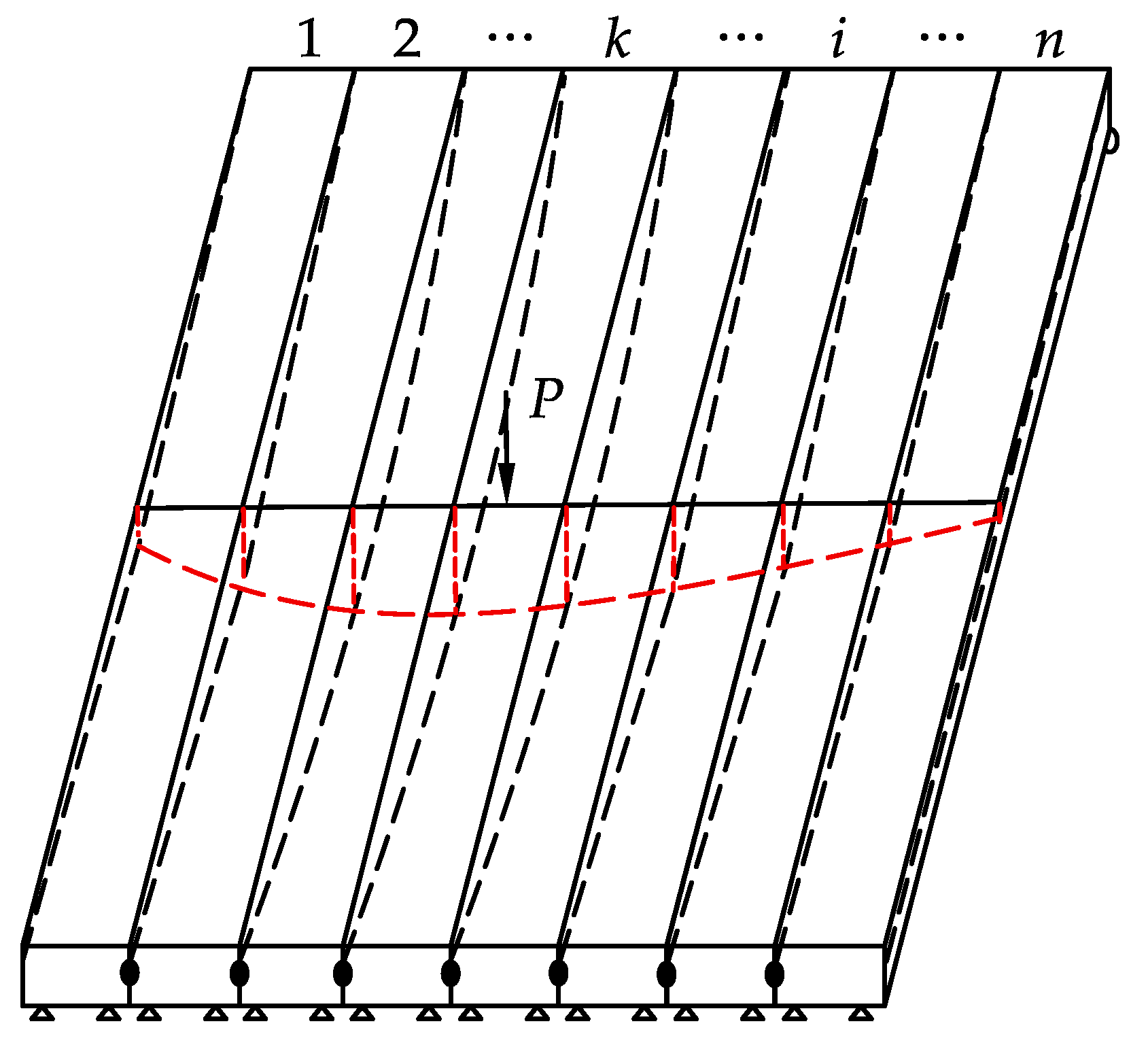
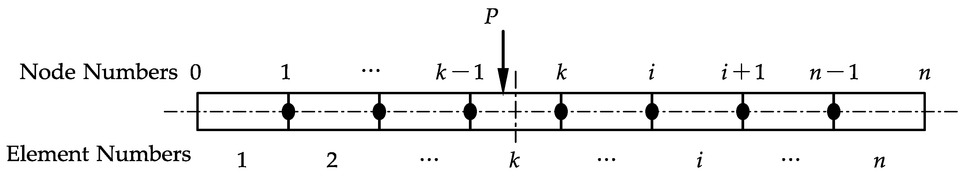
A typical articulated slab bridge consists of a number of parallel contiguous slabs associated with each other along their length by shear keys that transmit no bending moment. As illustrated in Figure 1, when a concentrated force P applies on the kth slab, part of the load is carried by the slab, and the rest will be transferred transversely to adjacent slabs by vertical shear forces via the hinges.
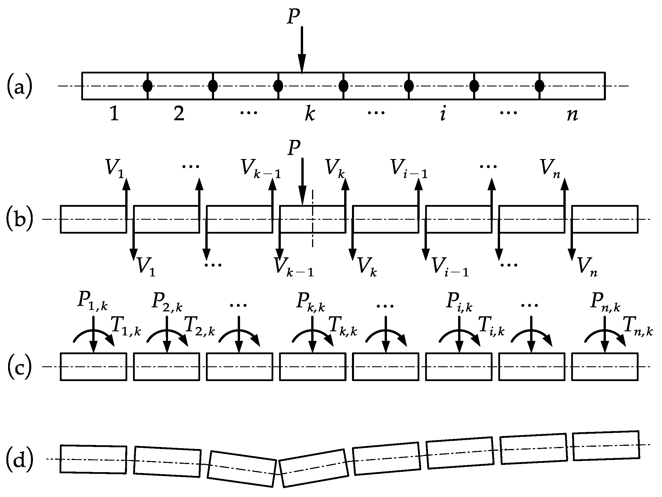
The transverse load distribution is the resultant forces transferred through the shear key on the rest of the slabs when a concentrated force acts on a certain slab. The midspan section of bridges is generally taken for analysis to calculate the shear force transferred between the slabs, as shown in Figure 2. Eventually, the transversely distributed loads, including vertical loads and transverse torques, are calculated for each slab, which is given by
where and are the distributed load and distributed torsion in the slab i coming from transverse distribution, respectively. and are the shear forces at joint i−1 and joint i, respectively; a is half-width of the slab, e is the eccentricity of the loading position from the centerline of the slab k.
Based on the above mechanical model, the TMM is used to analyze the TLD of the articulated slab bridges. In addition, the following basic assumptions are taken:
- (1)
- Ends of slabs are simply supported.
- (2)
- The torsional deformation of the slab end is restrained.
- (3)
- The slab sections have no warping deformation.
- (4)
- The lateral connection between the slabs is replaced by an articulated point in the loading position.
3. TLD Analysis of Articulated Slabs by FM
3.1. Review of Existing Methods
The existing methods for calculating the TLD of bridges can be roughly categorized into numerical and analytical methods. Although the numerical method based on finite element analysis has been widely used, the modeling process is tedious and time-consuming because of the creation of the model, in particular the grillage model. Thus, some analytical methods are reviewed here.
The lever rule method [24] assumes that the wheel load is only distributed to one or two adjacent beams. Although it is the simplest method, it usually overestimates load distribution and is generally applied to the bearing section. The eccentric compression method, also known as the rigid transverse beam method [25], assumes that the transverse rigidity of the bridge is infinitely high. The overall transverse deformation of the bridge always remains in a straight line, which does not agree with practical engineering. Furthermore, it is not applicable for articulated slab bridges. On the other hand, the orthotropic plate method [26] considers that the bridge, consisting of multiple beams, can be approximated as a rectangular plate with different longitudinal and transverse stiffnesses. Then, the elastic plate theory is used for the analysis, and the effect of Poisson’s ratio is ignored. The calculation process is cumbersome, and the concepts are abstract in this method.
3.2. Procedure of the FM
In a calculation model, a pair of shear forces in the joint were taken as unknowns. The calculation diagram is shown in Figure 2b. Assume that P is a unit force, the joint is considered as a hinge that only transfers the vertical shear force, and is the shear force of the ith joint (i = 1, 2, …, n−1). According to the FM principle, as shown in Figure 3, the canonical equation of redundant forces considering the characteristics of transverse connection was established, expressed as Equation (3).
where is the shear force at joint j; is the vertical relative displacement at joint i caused by the unit force acting within joint j; and is the vertical displacement caused by the external load P at joint k.
The calculation procedure of each constant coefficient in Equation (3) is detailed in Ref. [27]. According to Figure 3 and Equation (3), there are (n−1) unknown shear forces and (n−1) simultaneous equations for n slabs. In addition, the equation coefficient needs to be recalculated to obtain the TLD for each slab. Then, a system of linear equations must be solved again to derive each unknown shear force. It can be seen that using the FM principle to calculate the TLD of articulated slab bridges is tedious and requires substantial equations.
After calculating (j = 1, 2, …, n−1), the resultant vertical force on each slab can be obtained through their free body diagram. In case of the slab k subjected to the unit vertical force, this is exactly the TLD of each slab in the whole section.
4. TMM for the TLD Analysis
4.1. Transfer Matrix Derivation
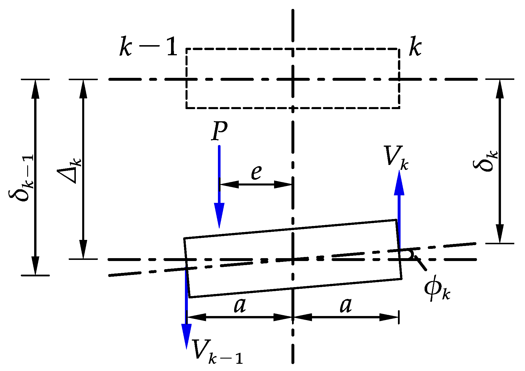
To perform a transverse analysis of the whole bridge deck, it reasonably starts from the slab subjected to the vertical load P, as shown in Figure 4. The left and right nodes of the slab are denoted as k−1 and k, respectively. Define the state vector at node k as:
where is the vertical displacement of the node k, and is the vertical shear force at the same node.
According to the differential equation of the deflection curve and torsion, the bending and torsion flexibility coefficients of the section at the loading position of an individual simply supported slab can be expressed as:
where d is the distance from the loading point to the support; L is the effective span of slabs; a is the half-width of slabs; E is the elastic modulus of concrete; G is the shear modulus of concrete, with ; is the Poisson’s ratio of concrete; and and are the bending inertia moment and torsional inertia moment of the slab section, respectively.
From Equations (6) and (7), the basic equations of force and deformation for slab k are established, and the relationship between the displacement and rotation on both sides of slab k can be obtained:
with
where and are the bending and torsion flexibility coefficients of section at the loading position of the slab k, respectively; d is the distance from the loading point to the support; and e is the eccentricity of the loading position from the centerline of the slab k.
According to simultaneous Equations (8)–(11), it can be deduced that:
where .
From Equations (12) and (13), and can be solved as:
The matrix forms of Equations (14) and (15) are as follows:
or
with
where and denote the state vectors of nodes k−1 and k, respectively; and is the field transfer matrix of the internal force and deformation of the left and right nodes of the slab under load P.
Similarly, the transfer matrix for the slab without external load (P = 0) can be written as:
with
where and denote the state vectors of nodes i−1 and i, respectively; and is the field transfer matrix of the internal force and deformation of the left and right nodes of the slab without load.
4.2. Transfer Equation Solution
The general case in this study is a bridge deck consisting of a number of slabs laid side-by-side and keyed together. Referring to Figure 5, individual slabs are numbered as 1, 2, 3, …, n, from left to right, and the hinge nodes between the slabs and two exterior nodes are also sequentially marked with Arabic numerals, from 0 to n.
Based on the deduction of Equations (17) and (19), the transfer equation between each slab can be expressed as:
It is noted that the above equation starts from the leftmost state vector , and ends with the rightmost state vector . It is possible to write the last state vector directly from the first one, by means of a global transfer matrix as:
or
where A is the global transfer matrix of the articulated deck, by successive multiplication of every transfer matrix.
It can be seen from Equation (23) that the global transfer equation involves only the boundary state vector but not the state vector of internal hinge nodes. If parameters E, I, G, J, L, and a are the same for each slab, then all the field transfer matrices are the same for all the slabs, except for the slab k, where the load P acts. Therefore, Equation (22) can be rewritten as:
with
The variables within the state vectors of the exterior nodes are the displacement and shear force, and the two lateral nodes of the exterior slab are the free ends. Therefore, for the global transfer equation above, the boundary condition is:
By substituting the boundary condition into Equation (23), it can be obtained that:
The solution is:
Thus, the state vector at node 1 is:
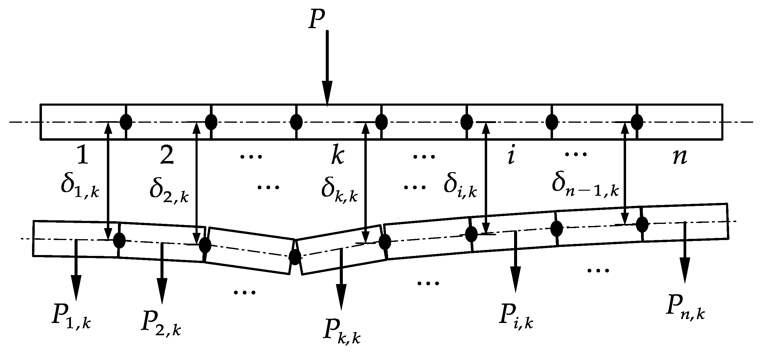
In light of the recursive equations in Equation (21), all the rest state vectors can be solved one-by-one. Since each state vector includes displacement and shear, the load and torque distributed to each slab under external load can be calculated using Equations (30) and (31). In addition, if the external load acting on slab k is a unit force, the influence line of TLD for slab k is the curve connecting the load distributed to each slab.
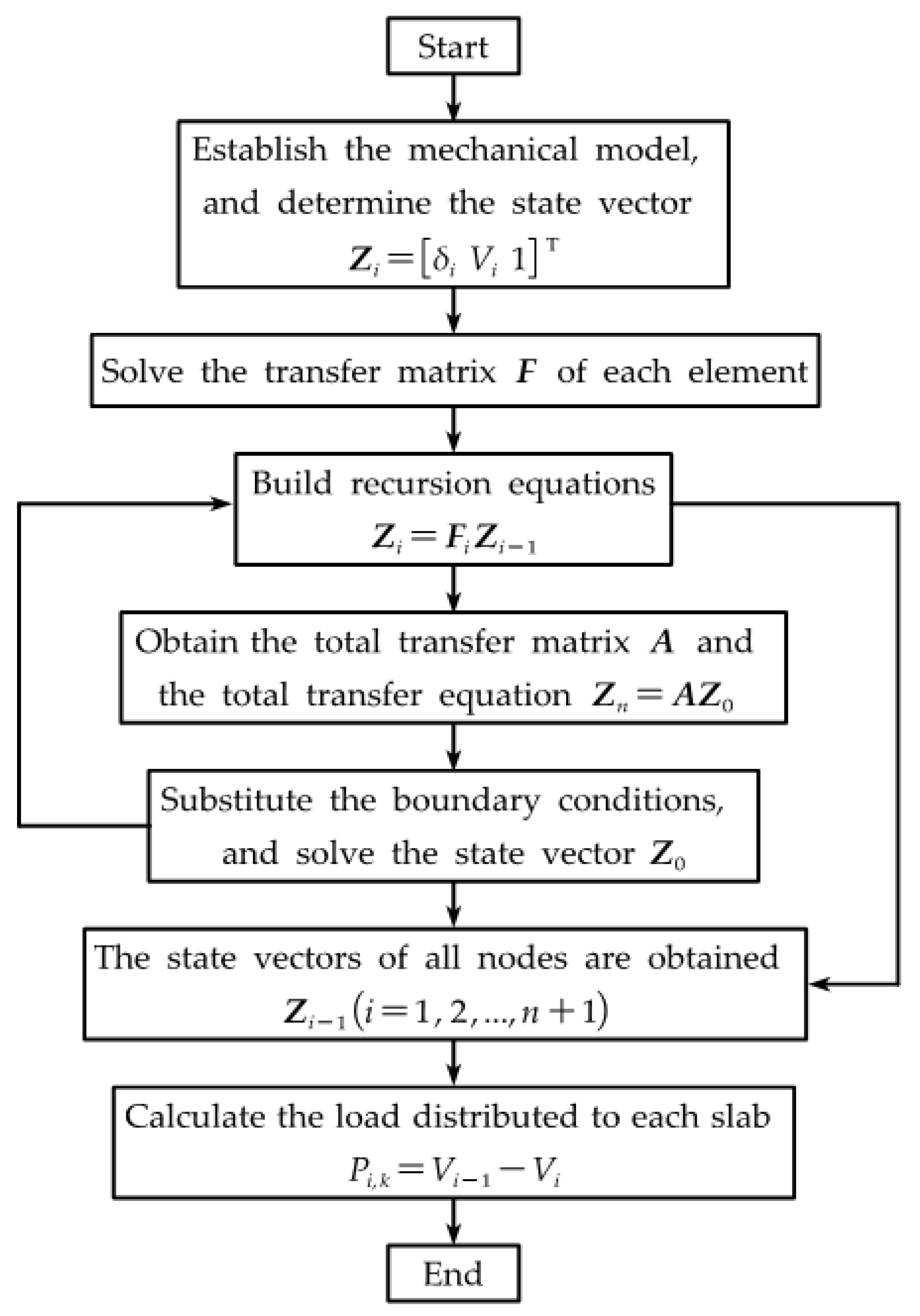
The MATLAB language was used to implement the calculation model. The flowchart of the implemented model is shown in Figure 6.
5. Illustrative Example
5.1. Overview
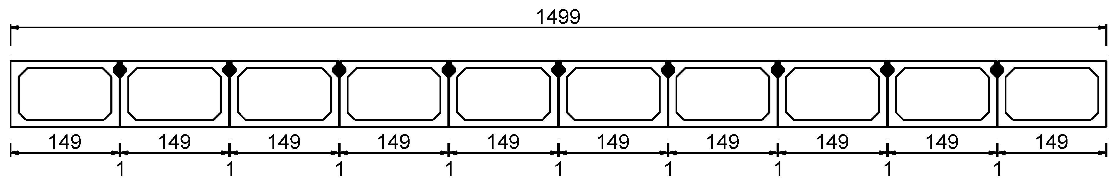
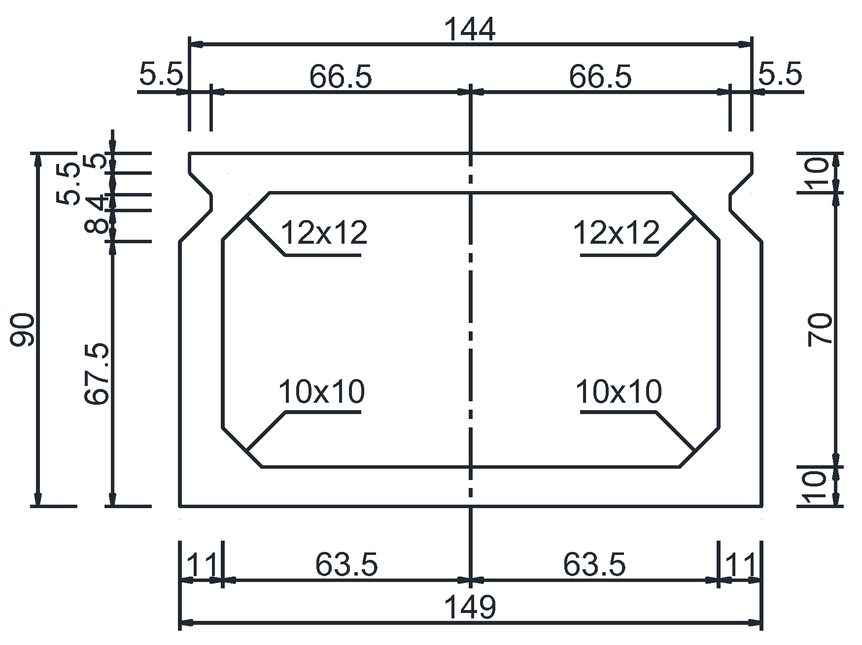
A transversely prefabricated void slab bridge with a span of L = 20 m; the influence line of TLD for each slab is to be solved. The bridge is horizontally composed of 10 prefabricated slabs, which are connected transversely by cast-in-place joint concrete. The prefabricated slabs and joints are made of C40 concrete. The transverse layout of the bridge and the cross-sectional dimensions of the void slabs are shown in Figure 7 and Figure 8. The calculating parameters in this paper are adopted as: a = 0.745 m, EI = 1.76 × 10⁶ kN·m2, and GJ = 1.70 × 10⁶ kN·m2.
5.2. Application of the TMM
The TLD for each slab is calculated according to Equations (30) and (31), derived in Section 4, assuming that the load acts on the vertical centerline of the slab cross-section. Taking Slab 1 as an example, the field transfer matrix can be given from Equations (18) and (20) as:
According to Equation (23), the global transfer matrix can be easily described as:
By very simple matrix operation, the state vector of each slab can be obtained by Equation (29), as shown in Table 1. Then, the distributed loads and torques for each slab can be calculated from Equations (30)–(31) as Table 2. The curve plotted with the values in the second row of Table 2 is also referred to as the influence line of the TLD for slab 1.
5.3. Finite Element Model
In order to validate the proposed method, a finite element model of the void slab bridge was constructed. Outstretching rigid arms were established along the bridge span between the slabs, and articulated joints were set between the rigid arms to transfer only the shear force, but not the bending moment. The finite element model, transverse connection configuration and boundary conditions are shown in Figure 9.
Furthermore, symmetry was considered when calculating the influence line of TLD for each slab. The unit load was applied to the centerline of Slabs 1–5 in turn, and the influence line of each slab was solved.
It is important to note here that there are multiple transverse connections along the longitudinal direction of the bridge in the finite element model. Therefore, the load transferred from the loaded slab to the other slabs is not a concentrated force. There are two approaches to calculate the TLD influence lines of slabs. One is to adopt the overall reaction force subjected to each slab as the load fraction. The other is obtained by the proportion of the displacement of each slab to the total displacement of the same cross-section [29], as shown in Equation (32). The latter is adopted in this paper.
where is load fraction for ith slab; is deflection of ith slab at the loading section; is deflection of jth slab; and n is number of total slabs.
5.4. Results and Discussions
5.4.1. The TLD of Slabs in the Midspan and L/8 Span
The TLD influence the lines of each slab in the middle, and L/8 span are calculated by TMM, FEM, and FM, respectively, as shown in Figure 10 and Figure 11. According to Figure 10 and Figure 11, the TLD influence lines of each slab in the midspan calculated by the TMM, FEM, and FM are very close, with influence line peak values difference within 10%. Furthermore, the TLD influence lines of each slab calculated by TMM and FEM in the L/8 span are still close, while the influence line peak values calculated by FM have a maximum difference of more than 15%, compared with FEM. It can also be seen from the figures that the influence line peak values gradually decrease from slabs 1 to 5, both at the midspan and L/8 span, thus indicating that the closer the external loading point is to the lateral center of the bridge, the more uniformly the load is distributed among the slabs. The above proves that the calculation method in this paper is adequate for engineering purposes.
In addition, compared with the conventional FM, TMM contains a smaller number of equations. On the other hand, it is obvious from Equations (18)–(22) that the transfer matrix of each slab and the global transfer matrix are always of order 3 × 3, regardless of the number of slabs. Therefore, compared with the FEM, the dimension of the matrix does not increase with the increased element numbers, which makes it convenient for hand or spreadsheets calculations, showing high overall computational efficiency and accurate results.
5.4.2. Variations of TLD along the Span
The TLD of slabs can be approximately calculated by the lever method when the load is applied near the bearing. Therefore, only the variations of TLD in the range of L/10 to 9L/10 span are analyzed in this paper, and the results are shown in Figure 12. According to Figure 12, both TMM and FEM can capture variations in TLD along the bridge span with similar results, while FM cannot. It is proven that the TMM has a wide range of applicability.
Figure 12 also shows that the variations of the TLD calculated by TMM are first decreased and then increased from the vicinity of the bearing to the midspan, while by FEM it decreases gradually, and the decreasing trend is becoming slower. This is caused by the fact that the TMM assumes that the transverse connection exists only at the loading position in order to simplify the calculation, and that the trends of bending and torsion flexibility coefficients from the bearing to the span are varied.
6. Effects of Parameter Variations on TLD
6.1. Span Length
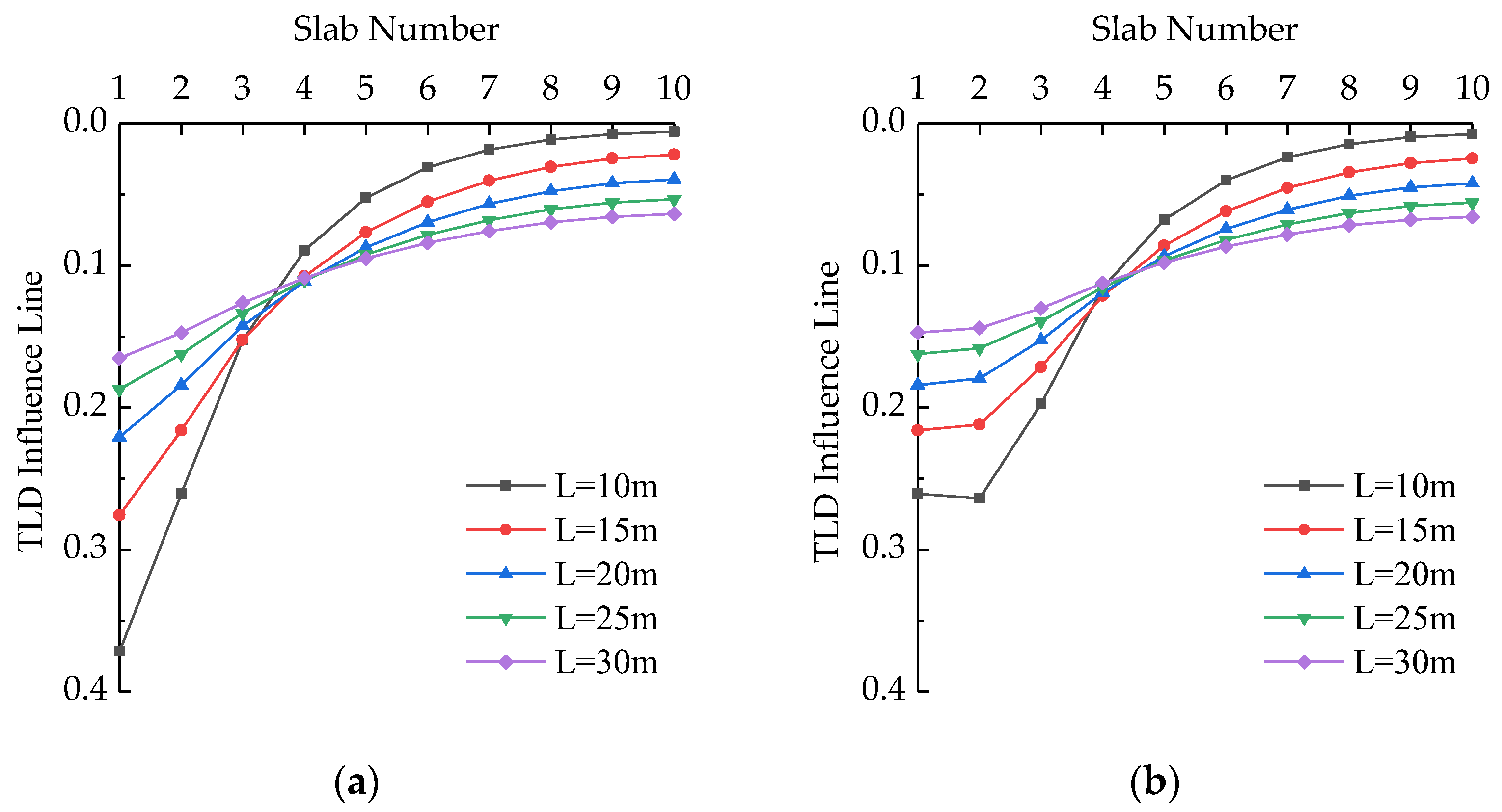
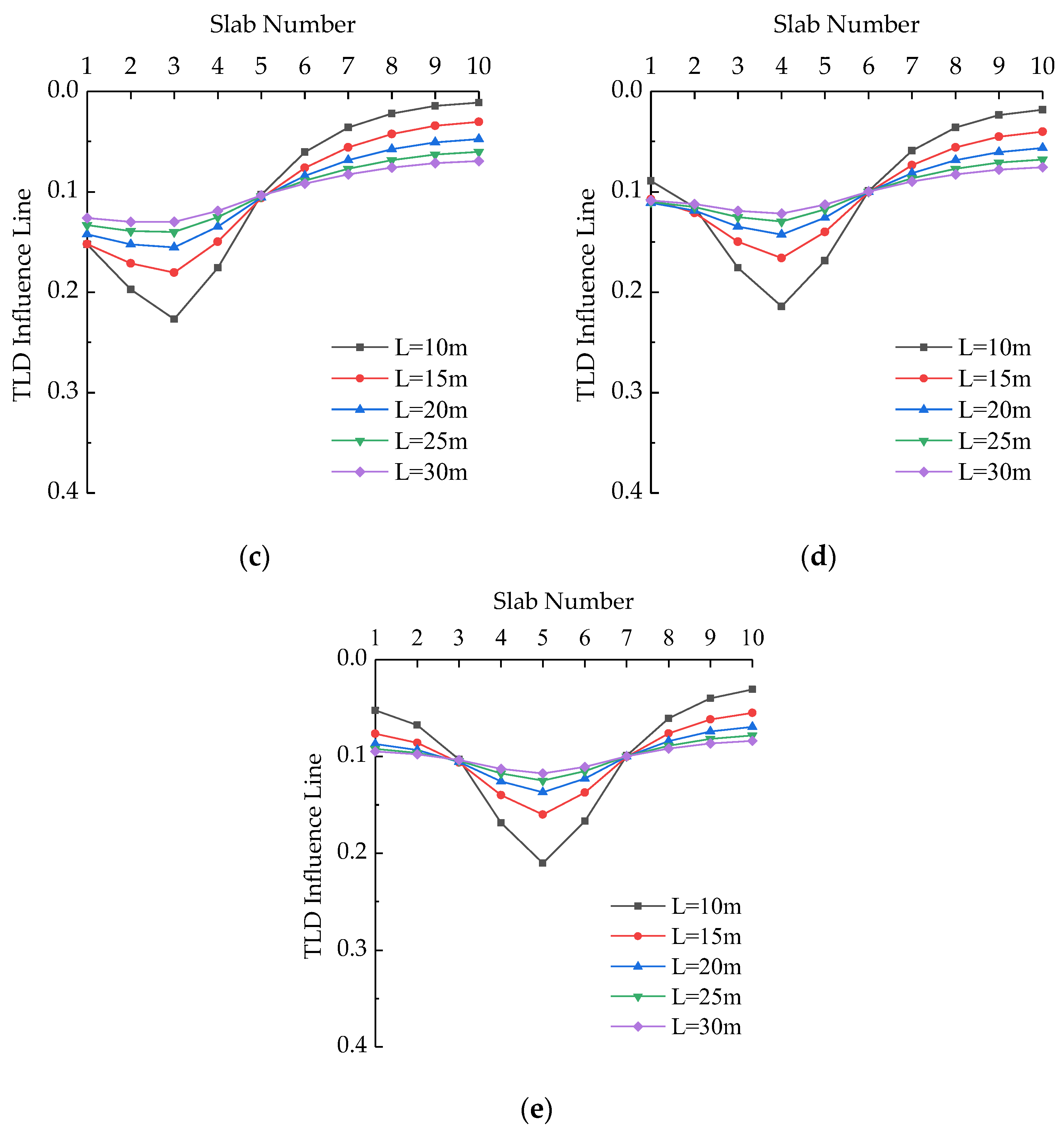
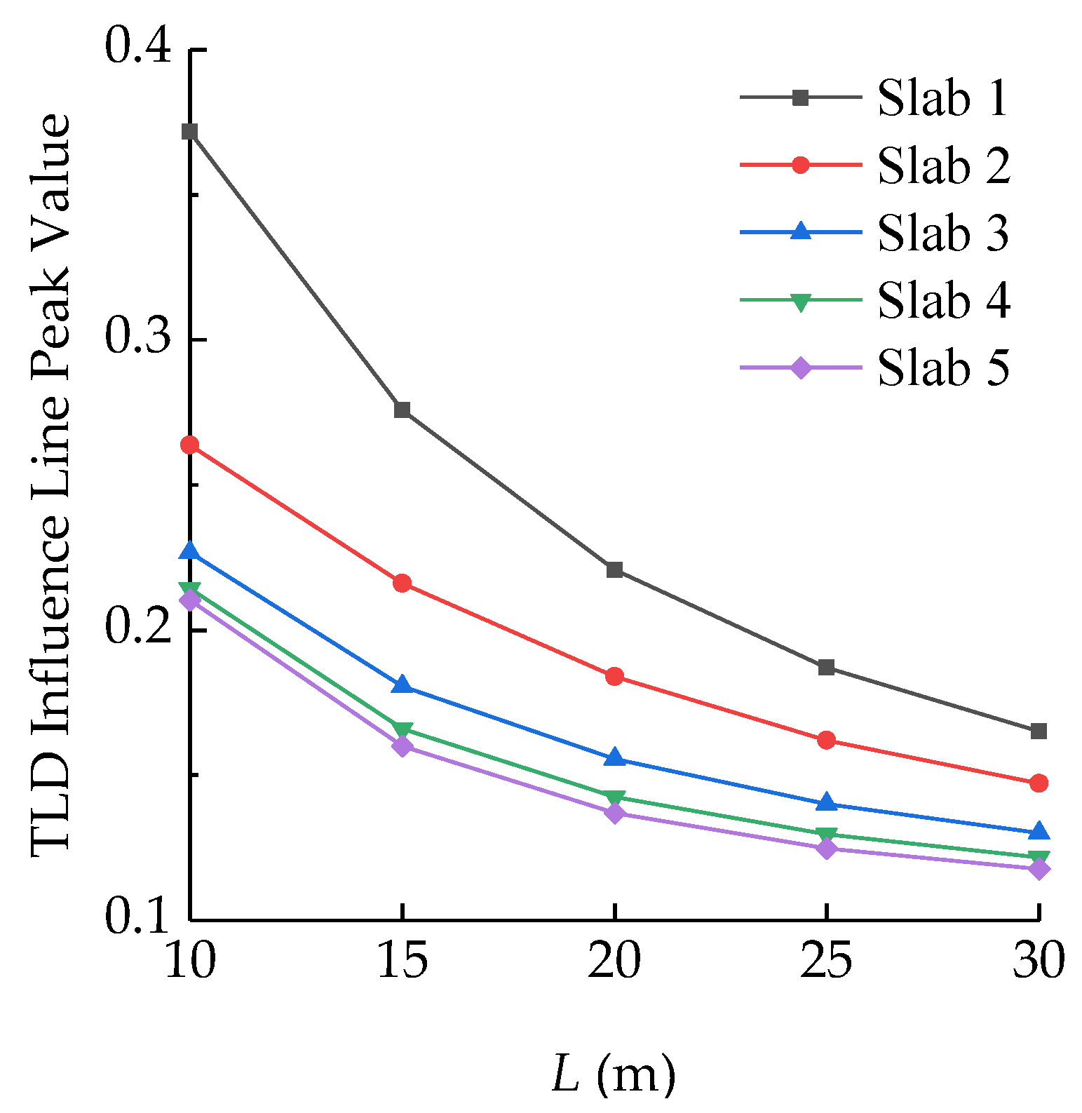
The effects of span lengths (10, 15, 20, 25, and 30 m) on the TLD for each slab were analyzed under the condition that both the cross-section and transverse quantity of slabs are constant. The results are shown in Figure 13 and Figure 14. It can be seen from Figure 13 that, as the span of the slab increases, the force on each slab under the load becomes more uniform. With other conditions unchanged, the increase of the span is equivalent to the increase of the span-width ratio of the bridge. The whole upper structure of the bridge can be regarded as a rectangular plate, and the load is easily transferred in the direction parallel to the short side. As shown in Figure 14, the peak influence line of each slab shows a non-linear decrease with the increase of the span-width ratio. It can also be seen from Figure 14 that the curve of the exterior slab is slightly steeper than that of the interior slabs, which is because the interior slabs are constrained by the adjacent slabs, and one side of the exterior slab is a free end. Moreover, the smaller the span-width ratio of a bridge indicates that the load on the slab near the loading position is higher. Therefore, for transversely prefabricated slab bridges, the span-width ratio of the bridge can be increased appropriately from the perspective of overall force uniformity.
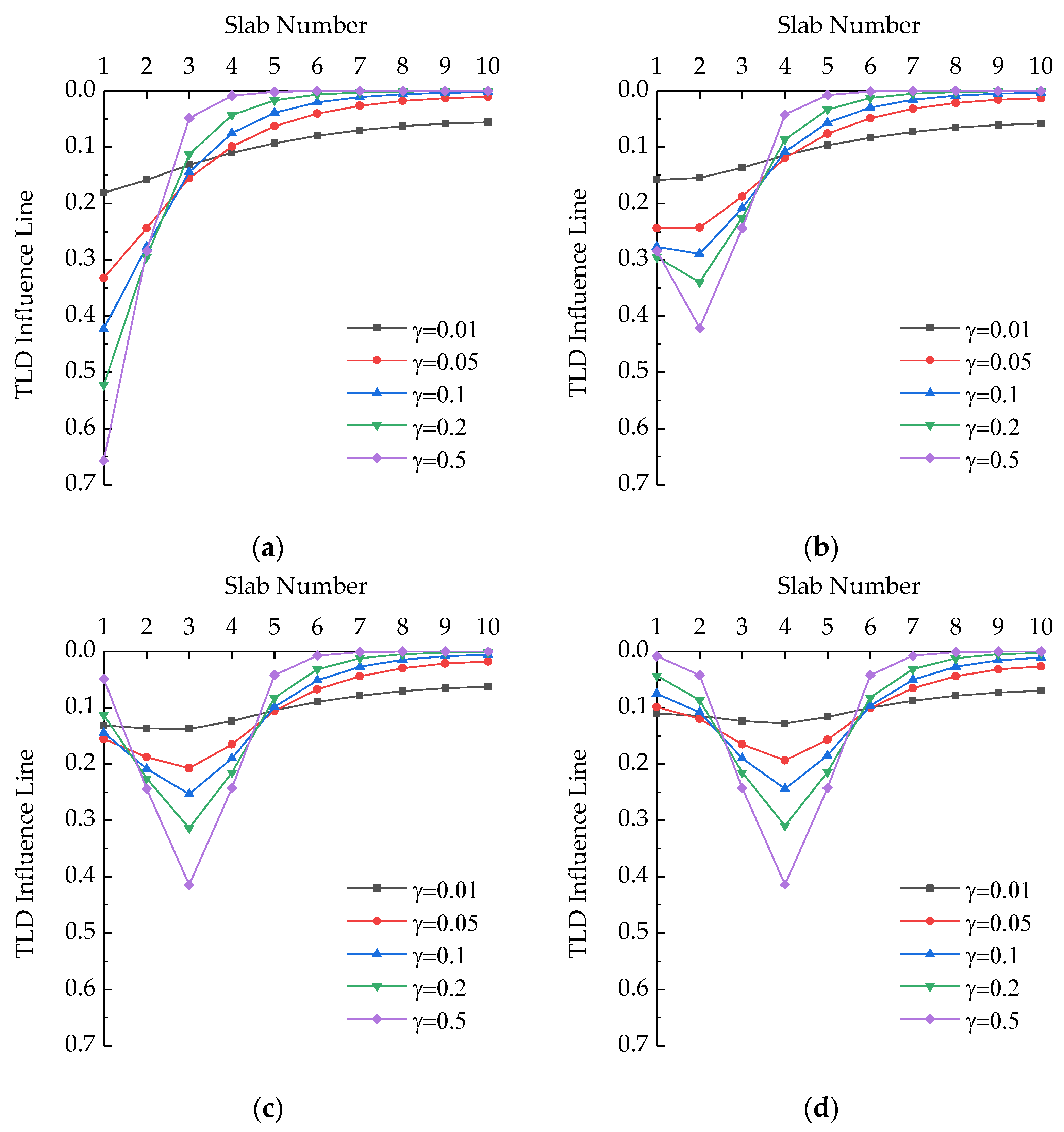
6.2. Relative Stiffness Coefficient
According to Equations (18) and (20), the field transfer matrix is only related to and when the applied load is determined. Additionally, is defined as the relative stiffness coefficient of the slab, and . The effects of (0.01, 0.05, 0.1, 0.2, and 0.5) on the TLD of the slab bridge were analyzed, as shown in Figure 15 and Figure 16. It can be seen from Figure 15 that the force of each slab becomes more uniform with the increase of . The increase in can be explained by the decrease in the torsional rigidity of each slab. Therefore, the inhibition of the deformation of the slab adjacent to the slab under the load is reduced. Figure 16 suggests that the peak values of the TLD influence lines for each slab are positively correlated with . As shown in Figure 16, the curve of the exterior slab is slightly steeper than that of the interior slabs, which is because the interior slabs are constrained by the adjacent slabs, while one side of the exterior slab is a free end. The lower torsional rigidity of the slab means that the slab near the loading position is subjected to a higher load. Therefore, from the overall force perspective, the box-shaped section is more advantageous than the T- or I-shaped sections.
7. Conclusions
(1) In this paper, the TMM is provided for calculating the influence line of TLD of articulated slab bridges. The field transfer matrix and transfer equation of each slab are developed, and the TLD of each slab is calculated by very simple matrix operations. The method avoids the large linear equations of bridge structures, which has a highly efficient algorithm and is easy for implementation in hand calculations, spreadsheets, or small computer programs.
(2) A transversely prefabricated void slab bridge is taken as an example, and FEM and FM are used to verify the method in this paper. The calculation results are very close, with maximum errors lower than 10%, thus proving the correctness and feasibility of the proposed method. In addition, TMM can capture variations in TLD along the bridge span compared with FM, which further proves the wide applicability of TMM.
(3) Under constant cross-sections and transverse quantities of slabs, the force on each slab under the load becomes more uniform as the span of the bridge became larger. The peak value of the influence line of TLD for each slab showed a non-linear decrease with the increase of the span-width ratio, and the decrease rate of exterior slabs is larger than that of interior slabs. In the design of transversely prefabricated slab bridges, a more uniform overall force can be achieved by appropriately increasing the span-width ratio of bridges.
(4) The peak values of the influence line of TLD for slabs increased with the increase of relative stiffness coefficients and rate of exterior slabs is larger than that of interior slabs. The lower torsional rigidity of slabs indicated that the slab near the loading position is subjected to a higher load. Therefore, from the overall force perspective, the box-shaped section is superior to the T- or I-shaped sections.
Author Contributions
K.G.: methodology, validation, investigation, formal analysis, writing—original draft. Z.L.: conceptualization, methodology, writing—review and editing, supervision, project administration. J.-M.B.: conceptualization, investigation, writing—review and editing. All authors have read and agreed to the published version of the manuscript.
Funding
This research was funded by the National Natural Science Foundation of China, grant number 51978161.
Institutional Review Board Statement
Not applicable.
Informed Consent Statement
Not applicable.
Data Availability Statement
The code and model presented in this study are available on request from the corresponding author.
Acknowledgments
The support provided by the China Scholarship Council (CSC), during a visit of the first author to Universitat Politècnica de Catalunya, is acknowledged.
Conflicts of Interest
The authors declare no conflict of interest.
References
- Huckelbridge, A.A.; El-Esnawi, H.; Moses, F. Shear Key Performance in Multibeam Box Girder Bridges. J. Perform. Constr. Facil. 1995, 9, 271–285. [Google Scholar] [CrossRef]
- Barbieri, D.M.; Chen, Y.; Mazzarolo, E.; Briseghella, B.; Tarantino, A.M. Longitudinal Joint Performance of a Concrete Hollow Core Slab Bridge. Transp. Res. Rec. 2018, 2672, 196–206. [Google Scholar] [CrossRef]
- Shi, W.; Shafei, B.; Liu, Z.; Phares, B. Longitudinal box-beam bridge joints under monotonic and cyclic loads. Eng. Struct. 2020, 220, 110976. [Google Scholar] [CrossRef]
- Kong, S.Y.; Zhuang, L.D.; Tao, M.X.; Fan, J.S. Load distribution factor for moment of composite bridges with multi-box girders. Eng. Struct. 2020, 215, 19. [Google Scholar] [CrossRef]
- AASHTO. AASHTO LRFD Bridge Design Specification, 9th ed.; American Association of State Highway and Transportation Officials: Washington, DC, USA, 2020. [Google Scholar]
- Zokaie, T. AASHTO-LRFD Live Load Distribution Specifications. J. Bridge Eng. 2000, 5, 131–138. [Google Scholar] [CrossRef]
- CSA. Canadian Highway Bridge Design Code, CAN/CSA-S6; Canadian Standards Association: Mississauga, ON, Canada, 2019. [Google Scholar]
- European Union. European Standard, Eurocode 1: Actions on Structures—Part 2: Traffic Loads on Bridges; European Union: Brussels, Belgium, 2020. [Google Scholar]
- Semendary, A.A.; Steinberg, E.P.; Walsh, K.K.; Barnard, E. Live-Load Moment-Distribution Factors for an Adjacent Precast Prestressed Concrete Box Beam Bridge with Reinforced UHPC Shear Key Connections. J. Bridge Eng. 2017, 22, 04017088. [Google Scholar] [CrossRef]
- Liu, H.; He, X.; Jiao, Y. Damage Identification Algorithm of Hinged Joints for Simply Supported Slab Bridges Based on Modified Hinge Plate Method and Artificial Bee Colony Algorithms. Algorithms 2018, 11, 198. [Google Scholar] [CrossRef] [Green Version]
- Zhao, Y.; Cao, X.; Zhou, Y.; Wang, G.; Tian, R. Lateral Load Distribution for Hollow Slab Bridge: Field Test Investigation. Int. J. Concr. Struct. Mater. 2020, 22, 8. [Google Scholar] [CrossRef]
- Whelchel, R.T.; Williams, C.S.; Frosch, R.J. Live-load distribution of an adjacent box-beam bridge: Influence of bridge deck. PCI J. 2021, 66, 51–71. [Google Scholar] [CrossRef]
- Ndong, A.K.; Sherif, M.M.; Kassner, B.; Harris, D.K.; Ozbulut, O.E. Potential Improvement in Rating Factors of Concrete T-Beam Bridges through Refined Analysis: Evaluation of Distribution Factors. J. Bridge Eng. 2022, 27, 04022081. [Google Scholar] [CrossRef]
- Aloisio, A.; Rosso, M.M.; Alaggio, R. Experimental and Analytical Investigation into the Effect of Ballasted Track on the Dynamic Response of Railway Bridges under Moving Loads. J. Bridge Eng. 2022, 27, 04022085. [Google Scholar] [CrossRef]
- Fu, C.C.; Pan, Z.; Ahmed, M.S. Transverse Posttensioning Design of Adjacent Precast Solid Multibeam Bridges. J. Perform. Constr. Facil. 2011, 25, 223–230. [Google Scholar] [CrossRef]
- Hussein, H.H.; Sargand, S.M.; Al-Jhayyish, A.K.; Khoury, I. Contribution of Transverse Tie Bars to Load Transfer in Adjacent Prestressed Box-Girder Bridges with Partial Depth Shear Key. J. Perform. Constr. Facil. 2017, 31, 04016100. [Google Scholar] [CrossRef]
- Labib, S.N.; El-Gendy, M.G.; El-Salakawy, E.F. Adjacent Concrete Box Girders Transversely Post-Tensioned at Top Flanges Only: Experimental Investigation. J. Bridge Eng. 2021, 26, 04021017. [Google Scholar] [CrossRef]
- Rui, X.; Wang, G.; Lu, Y.; Yun, L. Transfer matrix method for linear multibody system. Multibody Syst. Dyn. 2008, 19, 179–207. [Google Scholar] [CrossRef]
- Stephen, N.G. Repetitive beam-like structures: Distributed loading and intermediate support. Int. J. Solids Struct. 2009, 46, 3664–3668. [Google Scholar] [CrossRef] [Green Version]
- Stephen, N.G. On the Riccati transfer matrix method for repetitive structures. Mech. Res. Commun. 2010, 37, 663–665. [Google Scholar] [CrossRef]
- Tan, G.J.; Wang, W.S.; Jiao, Y.B. Free vibration analysis of a cracked simply supported bridge considering bridge-vehicle interaction. J. Vibroeng. 2016, 18, 3608–3635. [Google Scholar] [CrossRef] [Green Version]
- Kang, H.J.; Xie, W.D.; Guo, T.D. Modeling and parametric analysis of arch bridge with transfer matrix method. Appl. Math. Model. 2016, 40, 10578–10595. [Google Scholar] [CrossRef]
- Su, X.Y.; Kang, H.; Guo, T.D.; Cong, Y.Y. Modeling and Parametric Analysis of In-Plane Free Vibration of a Floating Cable-Stayed Bridge with Transfer Matrix Method. Int. J. Struct. Stab. Dyn. 2020, 20, 2050004. [Google Scholar] [CrossRef]
- Mensah, S.A.; Durham, S.A. Live Load Distribution Factors in Two-Girder Bridge Systems Using Precast Trapezoidal U-Girders. J. Bridge Eng. 2014, 19, 281–288. [Google Scholar] [CrossRef]
- Hołowaty, J. Live Load Distribution for Assessment of Highway Bridges in American and European Codes. Struct. Eng. Int. 2012, 22, 574–578. [Google Scholar] [CrossRef]
- Cheung, M.S.; Bakht, B.; Jaeger, L.G. Analysis of box-girder bridges by grillage and orthotropic plate methods. Can. J. Civ. Eng. 1982, 9, 595–601. [Google Scholar] [CrossRef]
- Li, G.; Shi, D. Calculation of Load Transverse Distribution for Highway Bridges; China Communications Press: Beijing, China, 1987. [Google Scholar]
- Wang, W.; Zhang, C.; Wan, S. Study on transverse load distribution of hinged hollow beam. IOP Conf. Ser. Mater. Sci. Eng. 2017, 269, 012052. [Google Scholar] [CrossRef]
- Harris, D.K. Assessment of flexural lateral load distribution methodologies for stringer bridges. Eng. Struct. 2010, 32, 3443–3451. [Google Scholar] [CrossRef]
Figure 1.
A typical articulated slab subjected to a concentrated force.

Figure 2.
The force diagram of articulated slab bridge: (a) applied external concentrated load, (b) vertical shear of joints, (c) distribution loads of each slab, and (d) deflections of slabs.
Figure 2.
The force diagram of articulated slab bridge: (a) applied external concentrated load, (b) vertical shear of joints, (c) distribution loads of each slab, and (d) deflections of slabs.

Figure 3.
Calculation model of the FM principle.

Figure 4.
The free body diagram of the kth slab.

Figure 5.
Schematic diagram of transversely hinged slabs.

Figure 6.
Flowchart of the TLD calculated by TMM.

Figure 7.
Transverse layout of the bridge (cm).

Figure 8.
Cross-sectional of a void slab (cm).

Figure 9.
The finite element model and connection configuration.

Figure 10.
The TLD influence lines of each slab in the midspan: (a) slab 1; (b) slab 2; (c) slab 3; (d) slab 4; (e) slab 5.
Figure 10.
The TLD influence lines of each slab in the midspan: (a) slab 1; (b) slab 2; (c) slab 3; (d) slab 4; (e) slab 5.

Figure 11.
The TLD influence lines of each slab in the L/8 span: (a) slab 1; (b) slab 2; (c) slab 3; (d) slab 4; (e) slab 5.
Figure 11.
The TLD influence lines of each slab in the L/8 span: (a) slab 1; (b) slab 2; (c) slab 3; (d) slab 4; (e) slab 5.

Figure 12.
The influence line peak values of TLD for each slab along the span: (a) slab 1; (b) slab 2; (c) slab 3; (d) slab 4; (e) slab 5.
Figure 12.
The influence line peak values of TLD for each slab along the span: (a) slab 1; (b) slab 2; (c) slab 3; (d) slab 4; (e) slab 5.

Figure 13.
The TLD influence lines of each slab at different spans: (a) slab 1; (b) slab 2; (c) slab 3; (d) slab 4; (e) slab 5.
Figure 13.
The TLD influence lines of each slab at different spans: (a) slab 1; (b) slab 2; (c) slab 3; (d) slab 4; (e) slab 5.


Figure 14.
The peak values of the TLD influence line of each slab at different spans.

Figure 15.
The influence lines of TLD for each slab at different relative stiffness.


Figure 16.
The peak values of influence lines of TLD for each slab at different relative stiffness.


Table 1.
The values of state vectors.
| State Vectors | Z0 | Z1 | Z2 | Z3 | Z4 | Z5 | Z6 | Z7 | Z8 | Z9 | Z10 |
|---|---|---|---|---|---|---|---|---|---|---|---|
| δ (10−5) | 2.22 | 1.97 | 1.52 | 1.18 | 0.92 | 0.73 | 0.59 | 0.48 | 0.42 | 0.38 | 0.36 |
| V | 0 | 0.78 | 0.60 | 0.45 | 0.34 | 0.25 | 0.19 | 0.13 | 0.08 | 0.04 | 0 |
| 1 | 1 | 1 | 1 | 1 | 1 | 1 | 1 | 1 | 1 | 1 | 1 |
Table 2.
The TLD of each slab under the unit force of slab 1.
| Slab No. | 1 | 2 | 3 | 4 | 5 | 6 | 7 | 8 | 9 | 10 |
|---|---|---|---|---|---|---|---|---|---|---|
| Load | 0.221 | 0.184 | 0.142 | 0.111 | 0.087 | 0.069 | 0.057 | 0.048 | 0.042 | 0.039 |
| Torque | 0.164 | 0.137 | 0.106 | 0.083 | 0.065 | 0.052 | 0.042 | 0.035 | 0.031 | 0.029 |
Publisher’s Note: MDPI stays neutral with regard to jurisdictional claims in published maps and institutional affiliations. |
© 2022 by the authors. Licensee MDPI, Basel, Switzerland. This article is an open access article distributed under the terms and conditions of the Creative Commons Attribution (CC BY) license (https://creativecommons.org/licenses/by/4.0/).
Share and Cite
MDPI and ACS Style
Guo, K.; Liu, Z.; Bairán, J.-M. Transfer Matrix Method for Calculating the Transverse Load Distribution of Articulated Slab Bridges. Buildings 2022, 12, 1610. https://doi.org/10.3390/buildings12101610
AMA Style
Guo K, Liu Z, Bairán J-M. Transfer Matrix Method for Calculating the Transverse Load Distribution of Articulated Slab Bridges. Buildings. 2022; 12(10):1610. https://doi.org/10.3390/buildings12101610
Chicago/Turabian StyleGuo, Kaiqiang, Zhao Liu, and Jesús-Miguel Bairán. 2022. "Transfer Matrix Method for Calculating the Transverse Load Distribution of Articulated Slab Bridges" Buildings 12, no. 10: 1610. https://doi.org/10.3390/buildings12101610
Note that from the first issue of 2016, this journal uses article numbers instead of page numbers. See further details here.