Article

Exploring the Processing of Tubular Chromite- and Zirconia-Based Oxygen Transport Membranes

Department of Energy Conversion and Storage, Technical University of Denmark, Frederiksborgvej 399, 4000 Roskilde, Denmark
*
Author to whom correspondence should be addressed.
Current address: Department of Mechanical and Aerospace Engineering, University of Central Florida, 12760 Pegasus Blvd, P.O. Box 162450, Orlando, FL 32816-2450, USA.
Current address: Department of Mechanical Engineering, Melbourne School of Engineering, The University of Melbourne, 173 Wilson Ave, Parkville VIC 3052, Australia.
Ceramics 2018, 1(2), 229-245; https://doi.org/10.3390/ceramics1020019
Submission received: 31 August 2018 / Revised: 22 September 2018 / Accepted: 27 September 2018 / Published: 29 September 2018
(This article belongs to the Special Issue Functional Ceramics for Energy Applications)

Abstract

:
Tubular oxygen transport membranes (OTMs) that can be directly integrated in high temperature processes have a large potential to reduce CO2 emissions. However, the challenging processing of these multilayered tubes, combined with strict material stability requirements, has so far hindered such a direct integration. We have investigated if a porous support based on (Y2O3)0.03(ZrO2)0.97 (3YSZ) with a dense composite oxygen membrane consisting of (Y2O3)0.01(Sc2O3)0.10(ZrO2)0.89 (10Sc1YSZ) as an ionic conductor and LaCr0.85Cu0.10Ni0.05O3−δ (LCCN) as an electronic conductor could be fabricated as a tubular component, since these materials would provide outstanding chemical and mechanical stability. Tubular components were made by extrusion, dip coating, and co-sintering, and their chemical and mechanical integrity was evaluated. Sufficient gas permeability (≥10−14 m2) and mechanical strength (≥50 MPa) were achieved with extruded 3YSZ porous support tubes. The high co-sintering temperature required to densify the 10ScYSZ/LCCN membrane on the porous support, however, causes challenges related to the evaporation of chromium from the membrane. This chemical degradation caused loss of the LCCN electronic conducting phase and the formation of secondary lanthanum zirconate compounds and fractures. LCCN is therefore not suitable as the electronic conductor in a tubular OTM, unless means to lower the sintering temperature and reduce the chromium evaporation are found that are applicable to the large-scale fabrication of tubular components.

1. Introduction

Oxygen transport membranes (OTMs) have the potential to reduce CO2 emissions from high temperature processes such as combustion and gasification [1,2]. Oxy-blown (oxygen rather than air) gasification or combustion would both reduce energy consumption through less inactive gas volume (N2) that has to be heated, and provide a N2 and NOx-free flue gas from which CO2 could be easily captured [1]. For biomass gasification, the higher oxygen content in an oxy-blown gasification will also significantly lower the tar content in the producer gas [3], which will increase its commercial value and enable its use in gas turbines. OTMs are dense ceramic membranes that only allow the transport of oxygen via oxide ion transportation [4]. If thermally and chemically integrated in, e.g., gasification plants such that the thermal energy for diffusion and driving force in the form of a pO2 gradient are supplied, OTMs will be a cost-efficient alternative to bottled oxygen produced by cryogenic distillation or pressure-swing adsorption [5].
However, such direct chemical and thermal integration of OTMs in real operating conditions has not yet been realized, due to manufacturing challenges and tough requirements on materials and components during operation. Single phase, mixed electronic, and ionic conductors such as Ba0.5Sr0.5Co0.8Fe0.2O3−δ (BSCF) as the membrane material can provide high oxygen flux [6], but these materials are often chemically and thermally unstable [7,8]. Changing from a mixed conductor to a composite membrane with two separate, percolating phases of electron and oxygen ion conducting material gives more flexibility to choose the most stable material combination for a given operation condition. Fluorite-structured oxides based on ceria or zirconia are well known ionic conductors [9,10]. Doping ZrO2 with Y and/or Sc increases its ionic conductivity in (Y2O3)0.01(Sc2O3)0.10(ZrO2)0.89 (10Sc1YSZ) up to 0.12 S cm−1 at 850 °C, while stability in CO2, SO2, and reducing conditions is retained [11]. Lanthanum-based perovskite-structured oxides with, e.g., Cr, Fe, and Sr are common choices for the electronic conductor. LaCrO3 is difficult to sinter due to the high volatility of Cr, but it possesses excellent stability over a wide pO2 range (0.21–10−22 atm) and can, upon acceptor doping, reach high electronic conductivity [12]. The composition LaCr0.85Cu0.10Ni0.05O3−δ (LCCN) was recently shown to reach 11.4 S cm−1 at 800 °C and have excellent stability in a wide pO2 range [13]. A composite membrane of 30 vol % LCCN and 70 vol % 10Sc1YSZ reached an oxygen flux of 1.02 mL cm−2 min−1 at 950 °C in N2/air in the shape of a planar thick film [13].
Thin OTMs (~10–30 µm) are advantageous compared to bulk OTMs (~150–1000 µm) [6,14,15]. Reducing the thickness of the membrane and hence the diffusion length of oxygen ions increases the oxygen flux, until a critical thickness is reached, where reduction and oxidation of oxygen at the membrane surfaces take over as the rate-limiting steps. Porous activation layers that increase the surface area and/or infiltrated catalysts facilitating these surface exchange reactions are therefore often added on either side of the thin membrane. When reducing the thickness, it is also critical that the membrane is dense and gas tight (has no percolating porosity), such that the membrane remains 100% selective to oxygen ionic transport dominated by diffusion.
Since these thin membranes cannot be free-standing, asymmetric oxygen membranes are made, with the membrane and activation layers deposited on a thicker porous support [16]. Supports that are a porous version of the membrane material [17] exclude chemical or thermal expansion mismatches. However, since the support needs to be highly porous for sufficient gas permeability and at the same time strong enough for integration and continued operation in, e.g., a biomass gasifier, inherently stronger ceramics are advantageous. Target values are gas permeability of ≥10−14 m2 and a strength of ≥50 MPa, based on considerations from references [17,18], respectively. ZrO2 with 3 mol % Y2O3 (3YSZ) has superior strength and toughness compared to practically all other oxide ceramics while being chemically stable, and it is therefore a commonly used porous support in solid oxide fuel cells and OTM [13,19].
Tubular membranes have advantages compared to planar, such as easier sealing and higher tolerance for thermal gradients [15]. Pilot-scale stand-alone units for oxygen production using tubular BSCF under compressed air/vacuum have already been made [16,20,21], and there are a few reports on the lab-scale fabrication and testing of other tubular OTM systems [22,23,24]; as it stands, tubular membranes with thermochemical stability allowing direct integration have not yet been made. Techniques to make flat and defect-free planar OTMs, such as stress relief through bending (camber), top loads for controlling this camber, two-step sintering, and enclosed crucibles or sacrificial powder beds [13,25], are not easily transferrable to large-scale processing of tubular systems.
In this work, we investigate if the combination of 3YSZ as porous support and LCCN/10Sc1YSZ as composite membrane is feasible for tubular OTM made by large-scale fabrication techniques. This membrane composition has demonstrated decent oxygen fluxes in a planar configuration [13], and the support composition has been proven suitable for high gas-permeability [26,27], but it has not yet been established whether sufficient mechanical and chemical integrity can be obtained after the more challenging co-sintering of a tubular system. Indeed, our work shows that while we can make strong and permeable 3YSZ support tubes, the high temperature required for co-sintering of LCCN/10Sc1YSZ on 3YSZ followed by evaporation of chromium makes LCCN unsuitable for large-scale fabrication of tubular OTMs.

2. Materials and Methods

Tubular supports were made by thermoplastic extrusion [28] of feedstocks containing 3YSZ powders, pore formers, and thermoplastic binders. The pore formers consist of a 2:1 volumetric ratio of graphite (SG FormulaBT SLA1518, Superior Graphite, Chicago, IL, USA) to polymetylmethacrylate (PMMA) (MR-10G, Esprix, Sarasota, FL, USA) and the thermoplastic binders a 2:1 volumetric ratio of ethylene-vinyl acetate copolymer (Elvax© 250, DuPont, Wilmington, DE, USA) and paraffin wax (melting point 53–57 °C, Sigma-Aldrich, St. Louis, MO, USA). Two different feedstock compositions were extruded in this work, feedstocks that, in the shape of small discs, provide the desired permeability (≥10−14 m2) over a wide sintering temperature range [26]. The first was with 40 vol % pore formers, 25 vol % 3YSZ (TZ-3YS-E, Tosoh, Tokyo, Japan) coated with 2.48 wt % stearic acid (Sigma Aldrich, USA), and 35 vol % thermoplastic binders, such that the pore formers constitute 61.5 vol % of the solid content (3YSZ powder and pore formers). The second feedstock composition was with 45 vol % pore formers, 25 vol % 3YSZ powder (TZ-3Y-E, Tosoh, Japan) coated with 5.36 wt % stearic acid (Sigma-Aldrich, USA), and 30 vol % thermoplastic, in which the pore formers constitute 64.3 vol % of the solid content. The feedstocks were mixed and kneaded at 100 °C (Type BK20, Hermann Linden Maschinenfabrik GmbH & CO, Marienheide, Germany), and then extruded (Model 19/20DN, Brabender, Duisburg, Germany) at 100–110 °C as 1 m long tubes of 14 mm diameter and 1 mm wall thickness. Binder-burnout and sintering in air was performed with the following program: 15 °C/h to 200 °C (2 h hold), 15 °C/h to 360 °C (2 h hold), 15 °C/h to 600 °C (4 h hold), 30 °C/h to the sintering temperature (1225–1400 °C) (2 h hold), and, finally, cooling at 120 °C/h. More details on the thermoplastic feedstocks can be found in reference [26]. Microstructure, porosity, Darcy gas permeability coefficient, and flexural strength of the sintered porous 3YSZ tubes were characterized by scanning electron microscopy (SEM) (TM3000, Hitachi, Japan), Hg porosimetry (Poremaster© GT, Quantachrome Instruments, Boynton Beach, FL, USA), and gas flow under total pressure gradient (in-house-constructed setup; for more details, see reference [26]).
Flexural strength of porous 3YSZ tubes was tested using four-point bending of semi-cylindrical samples. The test methodology is fully described in reference [29]. The main advantage of this methodology is that, upon flexure, maximum tensile stress is created in the middle region of the outer tube surface far away from any cut surfaces. The measured strength data will therefore not be affected by flaws introduced during machining. Time-consuming polishing of samples is thus not needed. Semi-cylindrical specimens also provide flat surfaces for contact with the loading pins. Semi-cylindrical porous 3YSZ samples were prepared by wet and dry cutting using diamond cutting tools. Four-point bending tests were conducted using specially designed equipment for continuous testing of multiple specimens under controlled environments [29]. Porous 3YSZ were bent until fractured at room temperature. At least six specimens were fractured for each type of porous 3YSZ; 32 specimens for the composition with 61.5 vol % pore former sintered at 1300 °C. Peak stress was determined from the recorded peak load via finite element analyses using the commercial software Abaqus. The measured fracture stresses of sample 61.5 vol % pore former sintered at 1300 °C were analyzed using the Weibull theory [30] to calculate the Weibull strength of porous YSZ.
Dip coating of membrane layers and activation layers onto the porous support and co-sintering was used to fabricate multilayered, asymmetric tubular OTMs. The general procedure was to first dip coat an inner porous layer directly on the as-extruded tubes, calcine; dip coat one layer of the composite membrane, pre-sinter; and dip coat a second layer of the membrane and one outer porous activation layer, followed by the final sintering. All dip coating was performed at 2 mm/s without any hold. The calcination program was similar to the debinding temperature profile described above, just with a lower final holding temperature of 1100 °C (instead of 1250–1400 °C). Pre-sintering was done a heating rate of 60 °C/h, 1 h dwell at 600 °C, 2 h dwell at 1150 °C, and cooling at 120 °C/h. The sintering program was identical to the pre-sintering program, except its final dwell temperature varied from 1250 to 1450 °C and its dwell time from 2–6 h. Tubes for co-sintering were kept below 40 cm in (green state) length, due to in-house limitations in high-temperature furnaces with a long enough sintering zone without thermal gradients.
Slurries for dip coating were made according to Table 1, based on previously developed OTMs [31]. A version of the activation layer slurry for increasing the porosity was made by increasing the pore former content to 10.6 wt % and decreasing the backbone content to 21.1 wt %, and a version with LCCN, also in the porous layer, to suppress evaporation of Cr, was made by further replacing 40 vol % of the 10Sc1YSZ with LCCN. All slurries were prepared by ball milling for 24 h (activation layer slurries)—72 h (membrane layer slurries). Pore formers were added to the slurry after 24 h, and milled with the slurry for 30 min. After milling, the slurries were stored while rolling and used for 3 months. The membrane layer-slurry was re-dispersed by ultrasound immediately before dip coating.
The microstructure of the sintered tubes were characterized by SEM (TM3000, Hitachi, Chiyoda ku, Japan and SUPRA35, Carl Zeiss, Oberkochen, Germany) and energy-dispersive spectroscopy (EDS) (JEOL JSM6400). Linear shrinkage was measured by contact dilatometry (Netzsch 402, Selb, Germany). Porosity in the membrane layer was estimated by segmenting the SEM images with the software ThreshAlyzer. Leak tightness of the membrane layer was evaluated by pouring ethanol into the tube and visually inspecting if any leakage occurred through the membrane.

3. Results

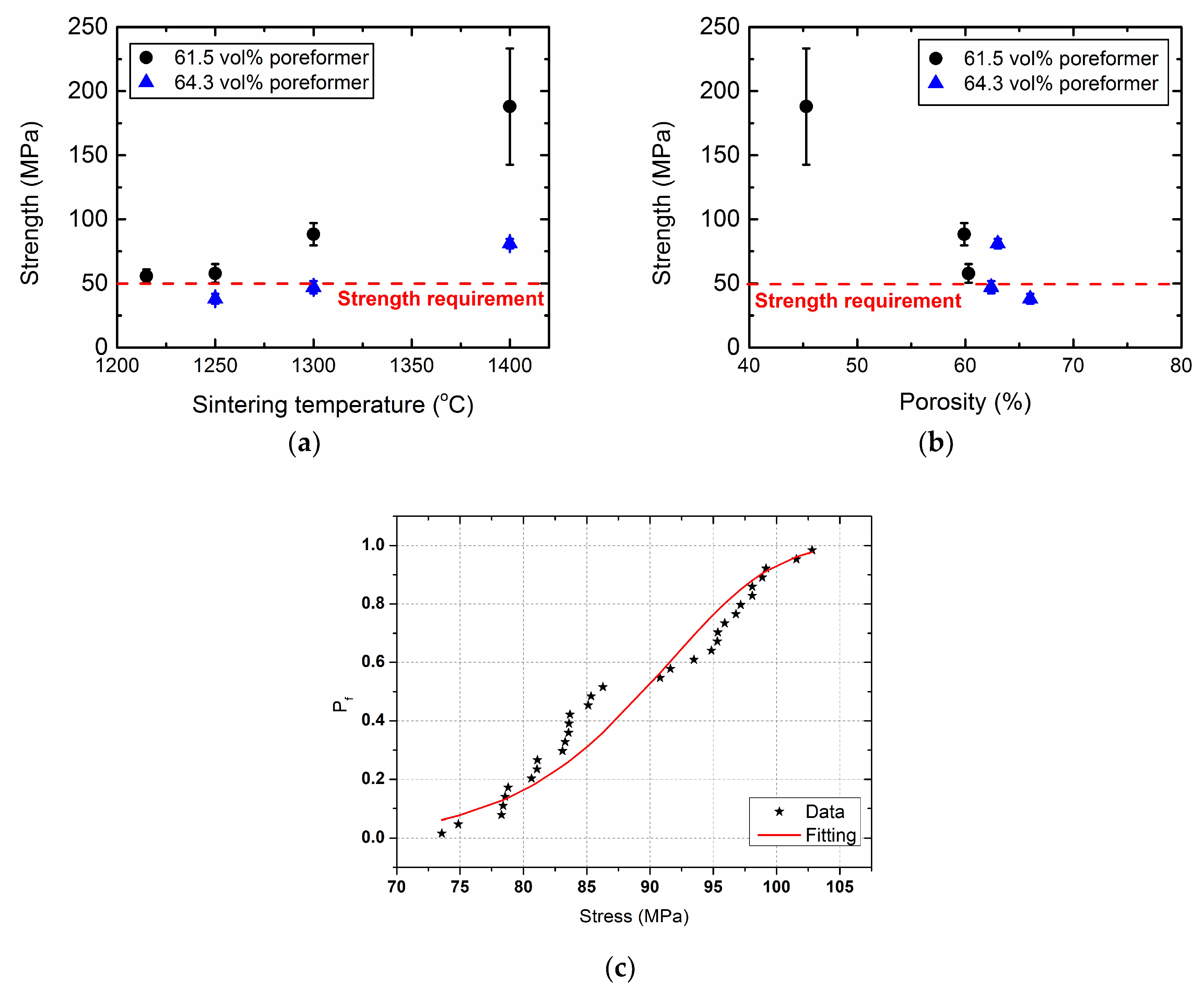
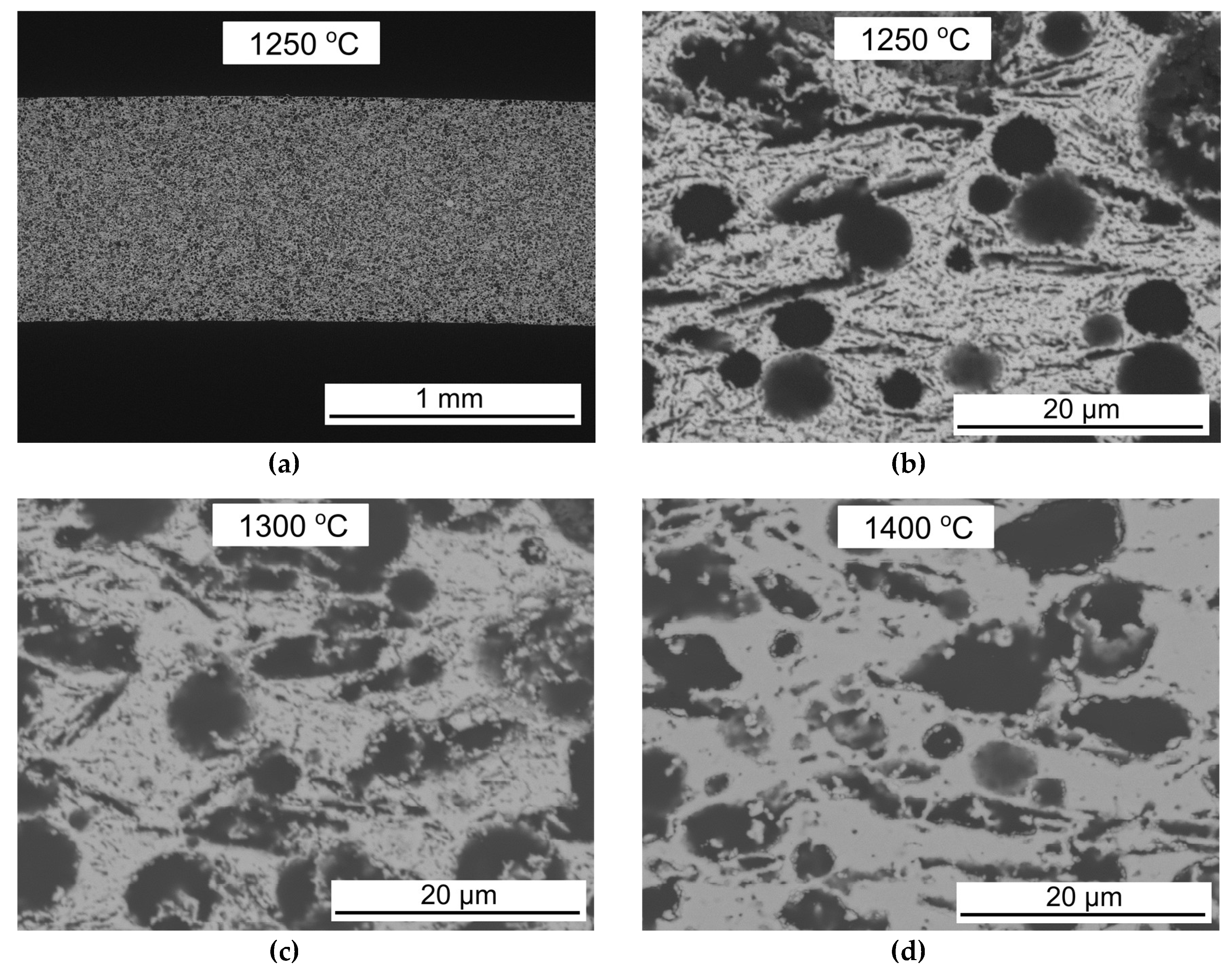
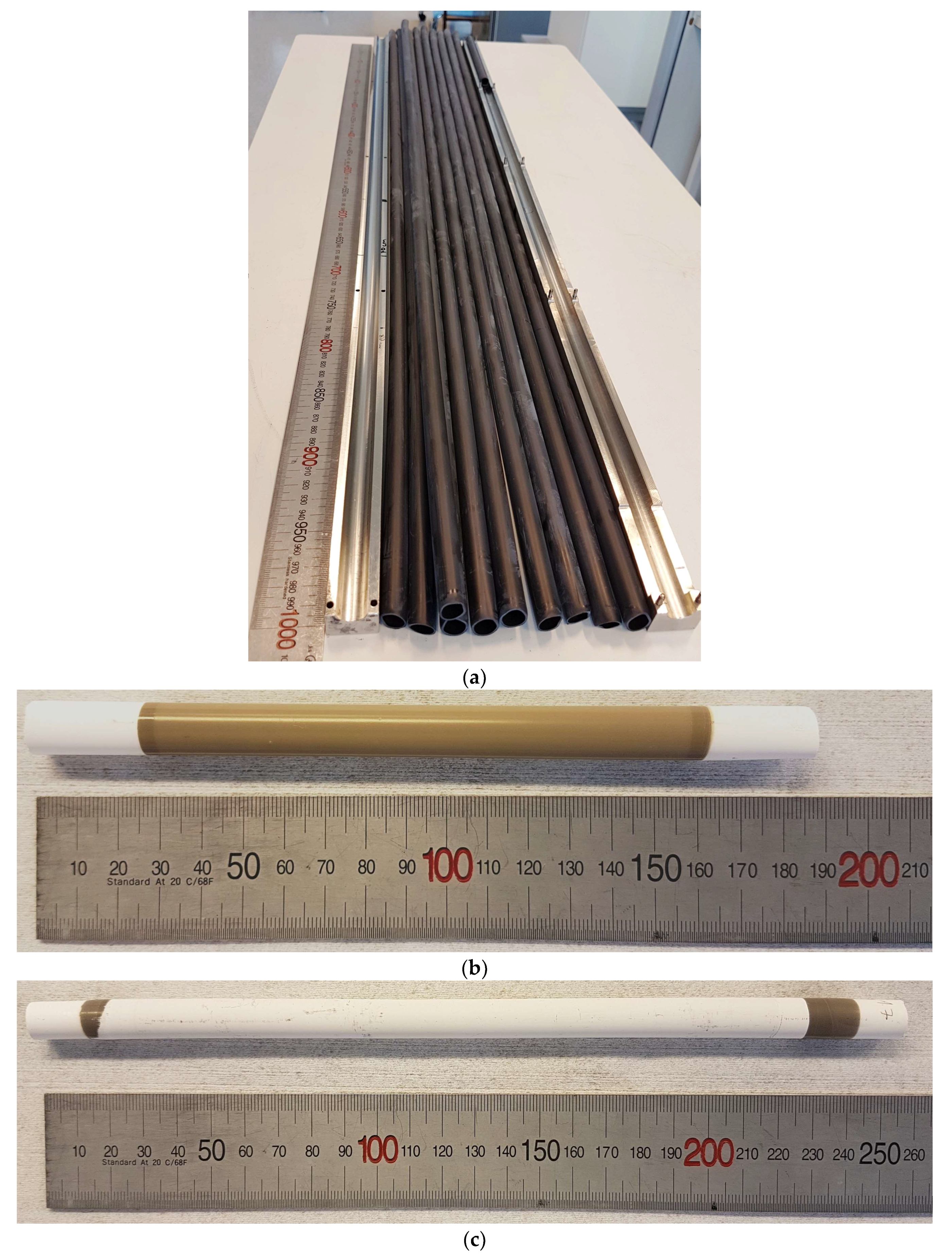
3.1. Porous 3YSZ Support Tubes

Figure 1 shows strength vs. sintering temperature and porosity of the two thermoplastic feedstocks for the porous 3YSZ tubes. Both compositions show a porosity content that is in good agreement with the amount of pore former, and decreasing strength with increasing porosity, as expected. While the tubes made with 64.3 vol % pore formers are too fragile at low sintering temperatures, the ones with 61.5 vol % pore formers fulfil the desired strength of 50 MPa after sintering. The 61.5 vol % pore former composition was therefore chosen for further development of the asymmetric OTM in this work. Figure 1c shows the Weibull plot for room temperature strength of the specimens sintered at 1300 °C with 61.5 vol % pore former. The measured strengths of the specimens are shown with the assigned probabilities of failure (Pf) and a fit of a Weibull distribution. Results of the Weibull fit show that the specimens have a characteristic strength and Weibull modulus of 92.19 MPa and 12.20, respectively.
The microstructure of the porous 3YSZ tubes at various sintering temperatures is shown in Figure 2. The material contains large (5–10 µm) spherical and large irregular pores, which originate from PMMA and graphite, respectively. There are also some small (<1 µm) pores within the 3YSZ matrix structure. The shape of the large pores is unaffected by the sintering temperature, but the small pores in the 3YSZ matrix structure diminish with increasing temperature. The porosity and gas permeability of the 3YSZ tubes are listed in Table 2. The porosity decreases as expected, and the pore size increases with increasing sintering temperature, with values similar to the initial studies on small discs of the same compositions [26]. Especially, the size of the smallest pores, represented by d10, increase with the sintering temperature. At all studied sintering temperatures, the gas permeability fulfils the target of ≥10−14 m2.

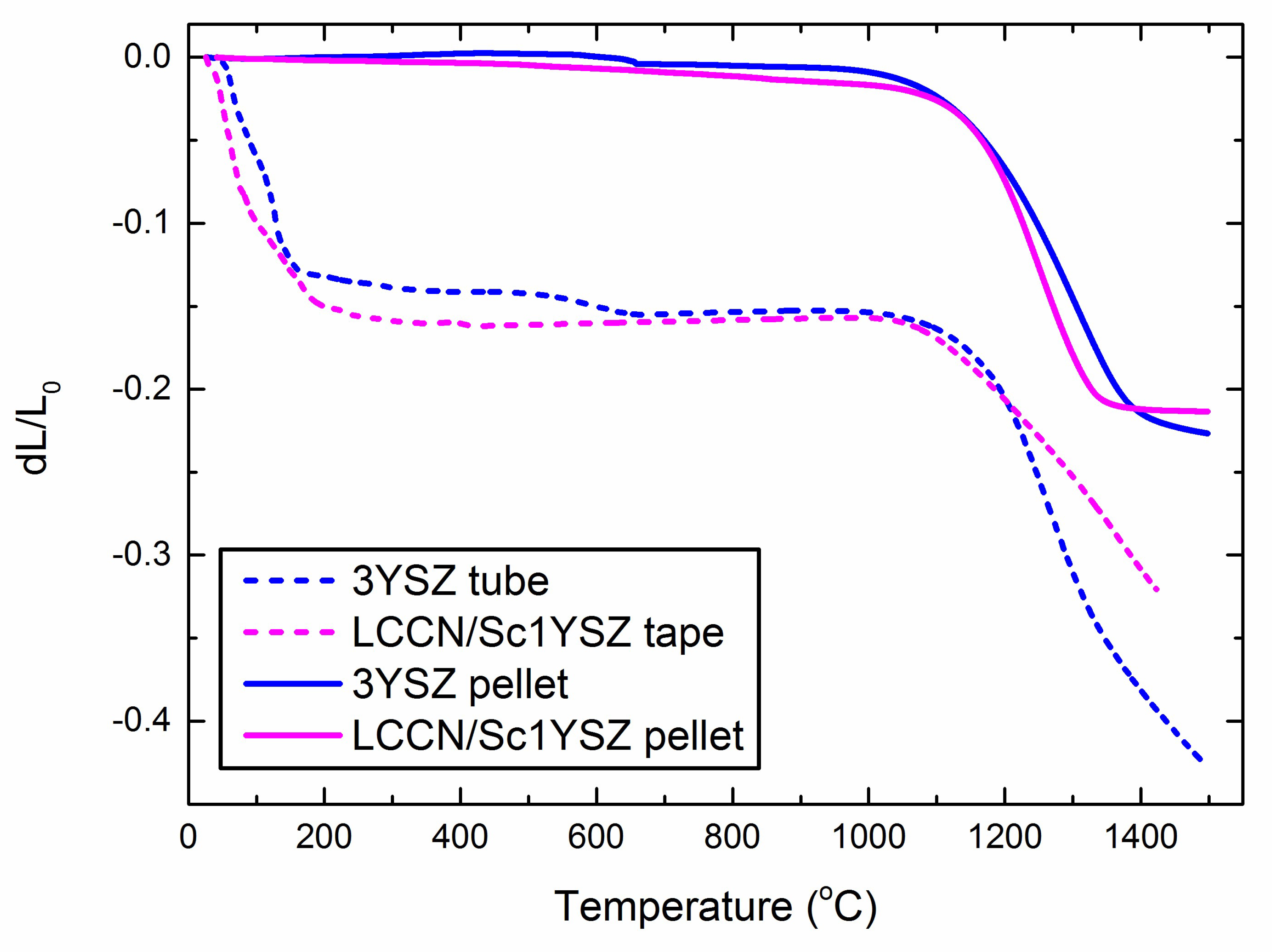
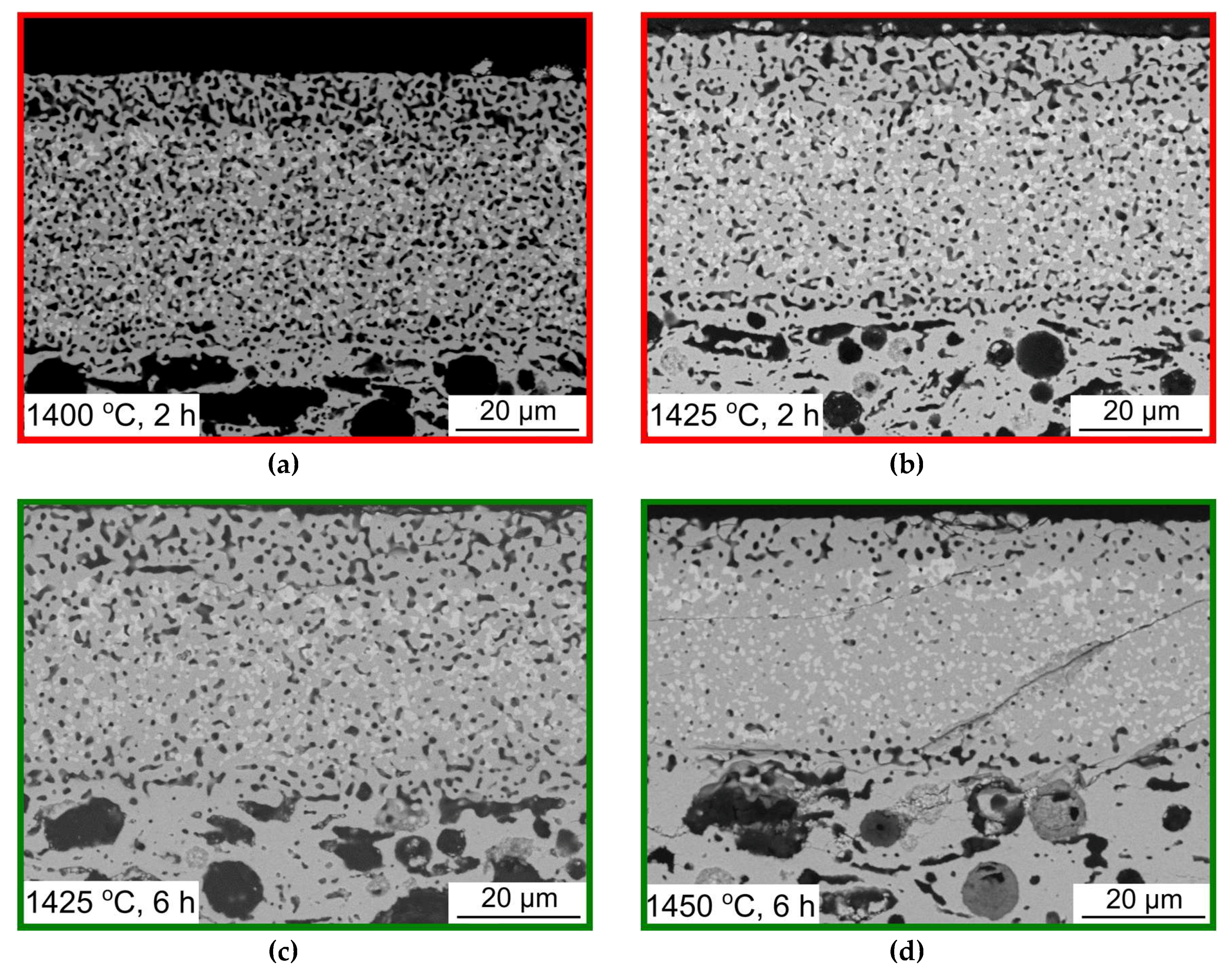
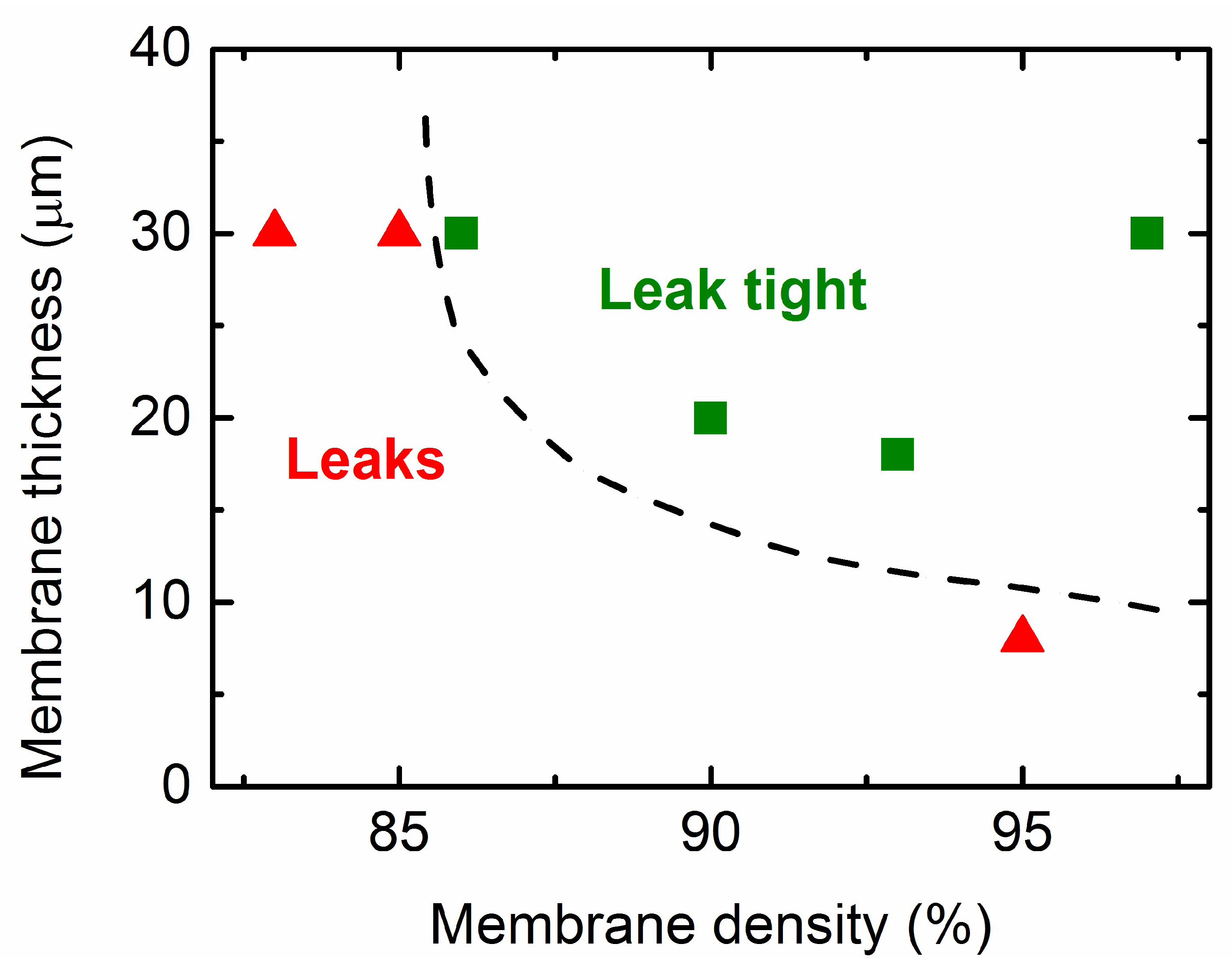
3.2. Co-Sintering of Membrane and Activation Layers on the Porous Support Tubes

Dilatometry curves of 30 vol % LCCN, 70 vol % 10Sc1YSZ (membrane composition), and 3YSZ (porous support composition) are shown in Figure 3. Both materials were measured in the form of pellet (compressed powder) and with organics for shaping (thermoplastic feedstock for the support tube, and a tape [13] as a substitute for the membrane dip coating slurry). The LCCN/10Sc1YSZ pellets densifies at <1400 °C, in good agreement with previous reports that pellets of the 70/30 composite membrane can be sintered dense at 1400 °C for 6 h [13]. The LCCN/10Sc1YSZ also densifies faster at a lower temperature than the 3YSZ. However, it is known that the sintering behavior can change upon addition of organics (different green density), pore formers, and with a change from bulk to thick film [6]. The free sintering of the membrane layer is not possible, but similar sintering behaviour for the dip coated membrane layer as for the tape can be expected. Compared to the pellets, the tape and tube show a high initial shrinkage due to the presence of organic additives, a similar onset temperature for sintering, and a reversed order of sintering activity; in this case, the densification of the 3YSZ tube is much higher than the LCCN/10Sc1YSZ tape.
Figure 4 shows photographs of the tubular OTM at different stages of the processing. Micrographs of cross sections of the OTM multilayers sintered at different temperatures and dwell times are shown in Figure 5. From top to bottom in each image is the outer activation layer (~5–15 µm), the composite membrane layer (~30–40 µm), the inner activation layer (~5–15 µm), and the porous support (only the first few µm visible). The bright phase in the membrane layer is expected to be LCCN, the darker 10Sc1YSZ. The black areas are pores. A membrane with sufficient density to be leak-tight (only a few small, leaky spots observed during leak testing) was obtained after sintering for 6 h at 1425 or 1450 °C. Sintering at 1425 °C for 6 h was therefore used as the standard procedure in further work. It is obvious that higher temperature is needed to densify the LCCN/10Sc1YSZ as a multilayer compared to previous reports on the bulk ceramic [13]. These findings are in accordance with dilatometry result (Figure 3). We can also see that some thin, longitudinal cracks are present in the membrane part of the as-sintered tubes after sintering at 1450 °C for 6 h (Figure 5d). In the other samples, such cracks can be observed to a lesser extent. These cracks are expected to be the origin of the leakage spots observed in the leakage test.
However, the leak-tight and apparently defect-free membrane sintered at 1425 and 1450 °C for 6 h was, upon closer inspection, found to have significant defects. Re-inspecting sintered tubes after heating to 300 °C for infiltration of catalyst in the activation layers, regularly separated cracks were observed by naked eye. Such macroscopic cracks were also observed to a lesser extent after storage for several weeks in ambient conditions, without any post-sintering treatment. In the less dense and leaky membranes sintered at 1400 °C, cracks were only visible by SEM microscopy investigation after a few weeks of storage. In general, the cracks were more pronounced and more advanced (visible immediately after storage) in the denser membrane layers sintered at higher temperature for a longer time. The cracks can be seen in Figure 6a. In contrast to the smaller, longitudinal cracks observed by microscopy immediately after sintering, these cracks are transverse (radial) through all the functional layers (membrane, inner, and outer porous layers) and separated by regular intervals. Adding a 10 h hold at 1100 °C (in which the creep rate in YSZ is still high [25]) during cooling after sintering did not prevent subsequent transversal cracking.
The membranes presented so far have a thickness of 30–40 µm. To avoid cracking, experiments to reduce the membrane thickness and number of layers were carried out. It was expected that thinner layers hold less energy and have a higher tolerance for strain mismatches [32]. Figure 6 shows how the kind of fracture appears to be related to the membrane thickness. The transverse cracks are only visible in thick (>30 µm) membranes (Figure 6a). Finer, longitudinal cracks or slight delamination of the outer membrane occur also in thinner membranes (8–20 µm) (Figure 6b), while very thin membranes (~4 µm) (Figure 6c) do not show any fractures. For oxygen transport, we need the membrane layer to be dense and gas tight. Whether or not the membrane leaks (as observed by the ethanol leak test) after sintering depends on a combination of it density and its thickness. Figure 7 shows that while 30 µm membranes can be leak-tight already at 86% density, membranes below 10 µm leak also when 95% dense.

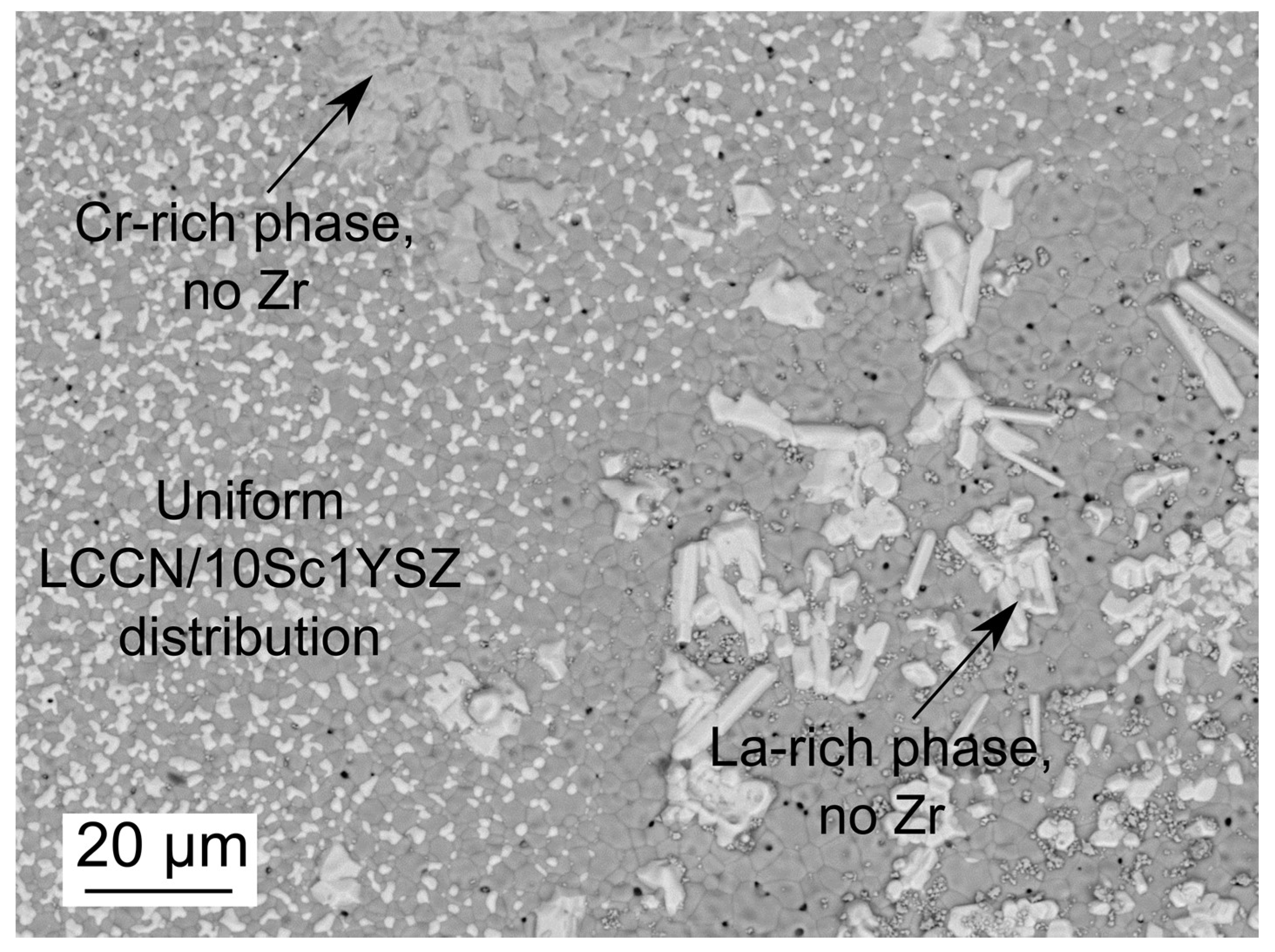
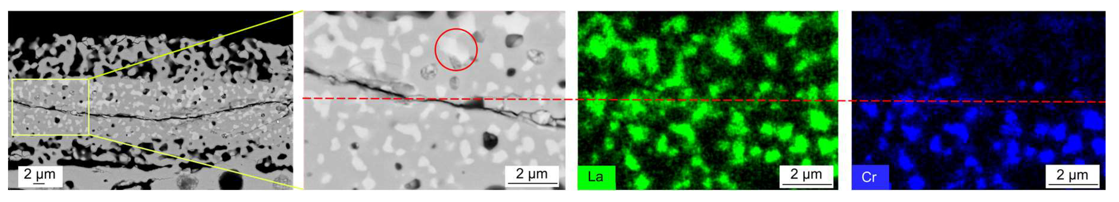
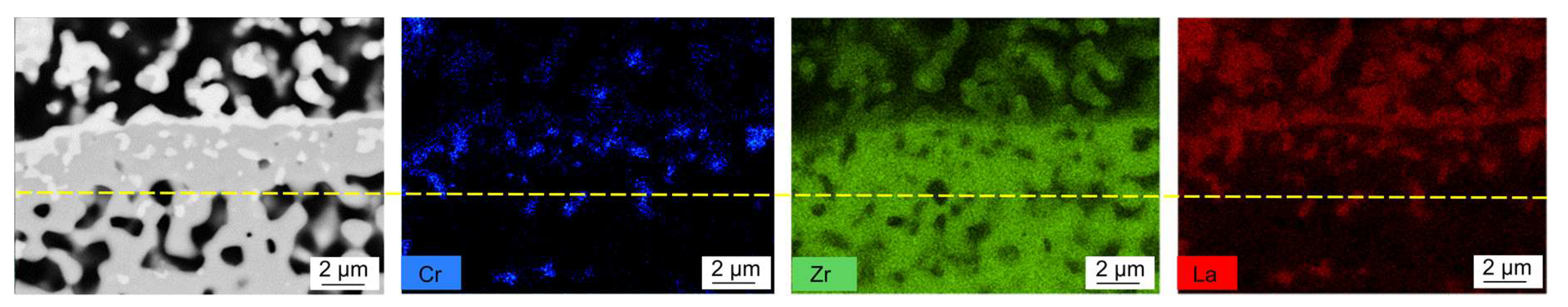
3.3. Cr Evaporation during Co-Sintering

The sintered top surface of a membrane layer without additional outer porous layer was analyzed to understand the chemical distribution of elements within the membrane. The micrograph in Figure 8 shows the regular, expected distribution of what appears to be the LCCN and 10Sc1YSZ phases in the composite membrane surface. In addition, two regions with other phases were found. EDS analysis reveal that these phases are (i) Cr-rich regions (not present in the thinnest membranes of only 4 µm) and (ii) La-rich needle-shaped agglomerates. These results indicate that the LCCN phase is prone to decomposition and forms other La and Cr rich phases.
Figure 9 shows the cross section of the OTM, including the porous activation layers, and a close-up EDS study of the region around a longitudinal crack. La is evenly distributed both above and below the crack. Cr on the other hand is mainly present in the region of the membrane closer to the inner porous activation layer and support, and almost completely depleted on the side of the crack facing the outer porous activation layer. The La:O ratio within the bright spots close to the outer part is 0.33, indicating the presence of La(OH)3. In contrast, the bright spots on the inner side still have Cr remaining in the LCCN phase. The bright grains are also larger in the outer part (see circle in Figure 9) than the inner part, indicating that the nominal LCCN grains grow when the Cr has been depleted. Upon closer inspection, it was found that the outer 4–10 µm of the membrane with a 10Sc1YSZ outer activation layer are depleted of Cr, while thin membranes without an outer activation layer (Figure 6c) show a complete loss of Cr from the membrane layer.
In the next set of experiments, additional LCCN (40 vol %) was added to the outer porous activation layer. Here the intention was that evaporation from this layer can saturate the environment immediate to the membrane surface with chromium and lower the driving force for evaporation from the membrane layer. Nevertheless, outer porous activation layers with higher fraction of LCCN than 40 vol % could not be sintered. Figure 10 shows the cross-section micrograph and EDS signals of Zr, La, and Cr with this approach. The SEM image shows a bright layer at the membrane-outer porous layer interface. This layer was found by EDS to contain La with Zr instead of Cr, in a Zr:La ratio of 2.1:1 and O:La of 7.6:1, indicating a LaZr2O7 secondary phase. Upon closer inspection, La,Zr secondary phases were observed also in membranes made without an outer porous activation layer or with the initial 10Sc1YSZ outer porous activation layer. Cr is present in the inner part of the membrane in Figure 10, associated with the bright phase in the SEM picture similar as seen in Figure 9. However, the stoichiometry does not add up to the LCCN phase, and the Cr:La is 0.55 rather than 0.85 as in the nominal LCCN phase. Also, Zr and Sc were found in the same spot, with a Zr:La of 20–60:1, indicating that most of the LCCN phase has decomposed and been replaced by a Sc,Y-doped ZrO2 phase. Due to low concentration of Ni and Cu in the sample, it is difficult to see their elemental distribution in the EDS maps, but results indicate an enrichment within the 10Sc1YSZ phase.

4. Discussion

4.1. Ceramic Processing of 3YSZ Porous Support Tubes

Thermoplastic extrusion has proven to be a suitable technique for the fabrication of porous support tubes for oxygen transport membranes. With 3YSZ as membrane support material, both high gas permeability and high strength could be achieved. Since the temperature required to densify the LCCN/10Sc1YSZ membrane was higher than expected (>1400 °C), and the membrane supports are quite dense and more than strong enough at 1400 °C, higher amounts of pore formers than 61.5 and 64.3 vol % could be considered to retain high gas permeability too after sintering at >>1400 °C. The strength of our 3YSZ tubes (Table 2) is similar to previously reported planar 3YSZ porous supports (~150 MPa at 45% porosity and ~100 MPa at 55% porosity) [19], twice as strong as porous MgO tubes (82 MPa at 42% porosity) [33], and more than four times as strong as porous BSCF tubes (20–36 MPa at 41% porosity) [6]. The gas permeability of the 3YSZ tubes is at the same time improved by an order of magnitude compared to those of MgO (4.7 × 10⁻¹⁶ m2) at similar porosity (42%) [33]. We have thus been successful at preparing strong, porous 3YSZ tubes that can be used for OTM supports integrated in mechanically and chemically harsh environments, or be used in other applications.

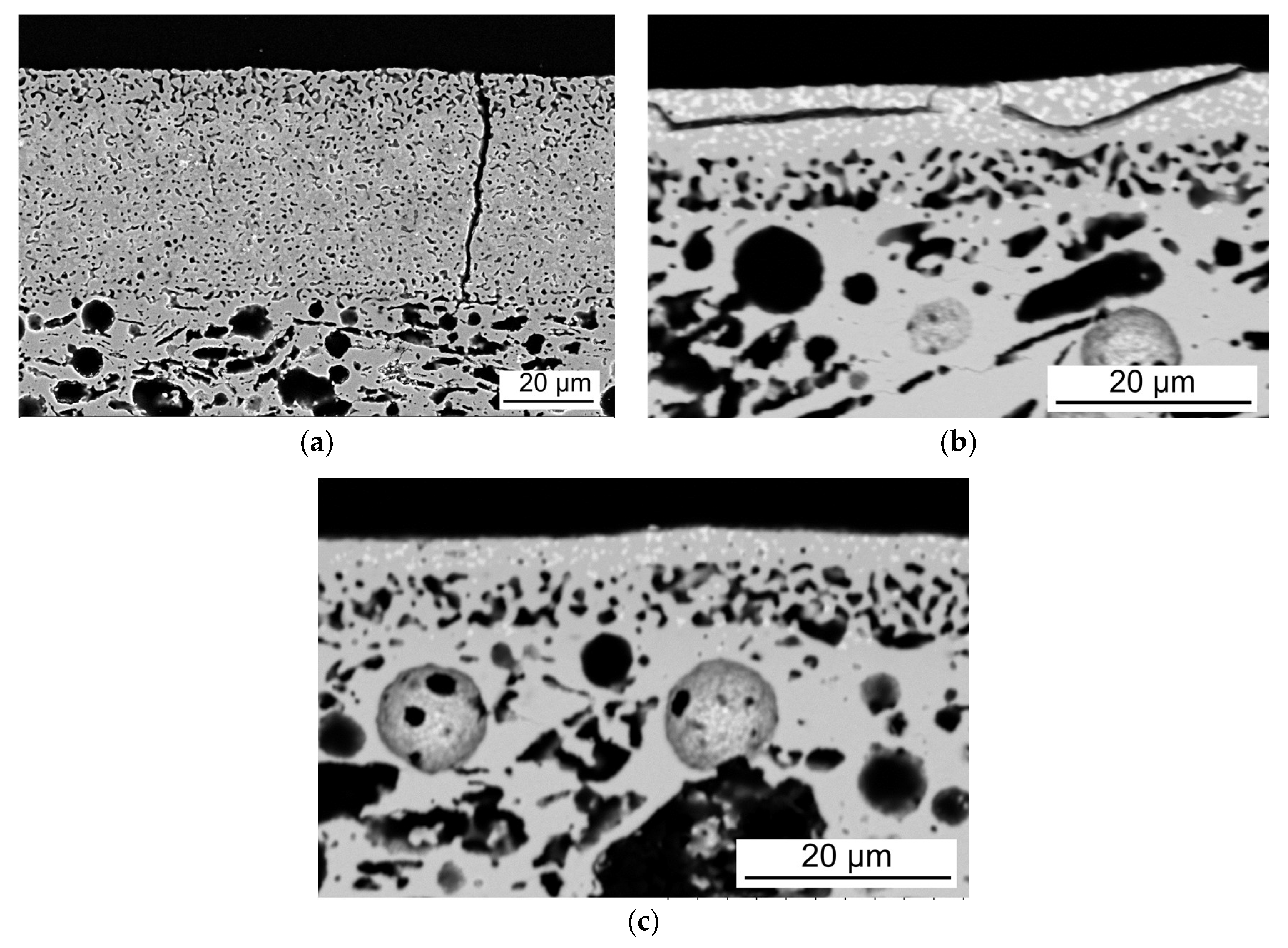
4.2. Crack Formation during Co-Sintering of Tubular, Asymmetric Oxygen Transport Membranes

Fractures, like the transverse and longitudinal cracks in our membranes, originate from stress mismatches within the membrane. Such stresses can be introduced during sintering, cooling after sintering, or storage. In an asymmetric, co-sintered system we expect that the thickest layer, in our case the porous support, dictates the total shrinkage of the multi-layered system [34].
The transverse cracks (Figure 6a) indicate that the membrane and the adjacent layers (inner and outer porous activation layers) have been under tensile stress. The similar shape of either side of the cracks also points towards the membrane fracturing while in its elastic regime, i.e., during cooling from sintering and below creep temperatures. Tension in this regime can originate from a higher thermal expansion coefficient (TEC) of the membrane compared to the support. TEC mismatches are known [35] to cause failures similar to those observed here, and would be our initial suggestion to explain the transverse cracks. Based on the average width and separation of the transverse cracks, the expansion, and hence also the TEC of the membrane, could be estimated to be 103% of the support. This TEC difference exceeds the acceptable TEC mismatch estimated (using equations from [32] and data for 8YSZ from [36]) for our >20 µm thick membranes. There are no previous reports on the TEC of the specific LCCN composition. The TEC of LaCrO3 (4.6 × 10⁻⁶ K−1 in the range 40–275 °C, 9.4 × 10⁻⁶ K−1 in the range 290–1050 °C, and 9.8 × 10⁻⁶ K−1 in the range 1100–1395 °C) [37,38] can be adjusted by doping to be similar to fluorite structured materials like zirconia [12]. Ni is expected to slightly decrease the TEC of LaCrO3, and Cu is not expected to increase it as much as elements with spin transitions such as Co [39]. We are therefore assuming LCCN to have a TEC of ~9.5 × 10⁻⁶ K−1. Comparing the estimated TEC of each layer in our tubular OTMs (Table 3), however, we cannot find any support for our hypothesis that TEC mismatches cause the transverse cracks, since the literature data clearly point towards the TEC of the membrane layer being smaller than that of the support.
Other possible causes of tension in the membrane and the transverse cracks are chemical reactions causing a volume reduction of the membrane, or a higher sintering rate of the membrane layer compared to the support. No secondary phases indicating chemical reactions were observed at the fracture surface of the transverse cracks. The most plausible cause of the transverse cracks is therefore sintering stresses. Relative differences in sintering onset temperature and sintering rates are known to strongly affect the mechanical stability of multilayered ceramics [6,42,43], and the thin layer that is in tension in the early stage of sintering is most susceptible to failure [44]. A higher sintering rate of the LCCN/10Sc1YSZ membrane compared to the 3YSZ support from ~1200 °C is seen in the dilatometry studies on pellets (Figure 3). This places the membrane layer under tension, and the resulting stress-buildup is released by cracking, either immediately during sintering, during cooling, or possibly later when triggered by, e.g., thermal stress during infiltration.
Longitudinal cracks were also observed in many of the membranes and were spatially correlated with depletion of Cr (Figure 9). When sufficient amounts of Cr have evaporated from the outer part of the membrane, the LCCN perovskite will decompose and La-based secondary phases, e.g., La2O3, form. La2O3 is known to easily hydrate to La(OH)3, accompanied by a large volume increase [45]. This local expansion might cause the longitudinal cracks in the zone between the Cr-depleted and the nominal regions within the dense membrane. It is also not possible to exclude TEC mismatches as the cause of some of the transverse cracks seen after sintering at high temperature (Figure 5d). The adherence between the different layers is strong, since we do not see delamination between them [25].
The cracks, both transverse and longitudinal, are only observed in the thickest membranes and after a certain degree of densification. The lower stiffness of porous compared to dense layers can make porous layers more able to tolerate strain [18]. Furthermore, thinner membranes are in general expected to be more crack-resistant, since the total energy to be released is smaller than for thicker layers [32]. Still, reducing the thickness of the membrane (e.g., to below 8 µm) to avoid cracking is not a viable solution, since it jeopardizes the leak-tightness crucial for selective transport of oxygen by ionic diffusion through the OTMs and causes depletion of Cr throughout most of the membrane thickness. Completely establishing the origin of the different mechanical failures in our system would require its own designated study and is out of scope of this work.

4.3. Evaporation of Cr

The volatility of chromium in LaCrO3 at high temperatures is a well-known challenge [12]. Since a high sintering temperature (≥1425 °C) was required to densify the composite membrane in our work, it is not surprising that we also encountered loss of Cr from the outer membrane part. Additionally, the LCCN in the inner part of the membrane, where the LCCN phase initially appeared intact as bright areas in the SEM images, are probably compromised, since these areas also contain Zr and less Cr than nominally, and since Ni and Cu are found outside of the nominal LCCN regions. Some of the Cr observed by EDS might also be from Cr redistributed by evaporation and condensation [12], similar to the Cr-rich agglomerates observed on the membrane surface in Figure 9. Upon evaporation of Cr (and possibly also Ni and Cu) from the B-site of the perovskite LCCN, it decomposes, and La reacts with Zr from 10Sc1YSZ instead. The LaZr2O7 phase observed in significant amounts at the interface between the membrane and outer porous layer is an insulating phase and is detrimental to the electrical conductivity of the OTM. Similar negative effects of such a La,Zr phase at interfaces were reported before in solid oxide fuel cells [46,47].
The evaporation in oxidizing atmospheres is assumed to occur according to Equation (1) [12]:
2LaCrO3 (s) = La2O3 (s) + Cr2O3 (g)
Thus, the creation of a local atmosphere at the membrane surface saturated with Cr2O3 (g) will shift the reaction (1) towards the left and stabilize the solid perovskite. This approach is used in many systems with volatile components, by adding top plates, powder beds, and/or closed crucibles. These configurations are not feasible for large, tubular components, but we aimed to achieve a similar effect by adding LCCN to the outer porous activation layer, where the high surface area should promote evaporation of Cr from the porous layer rather than the membrane and thus saturate the atmosphere to limit further evaporation. This approach was, however, not sufficient to reduce the evaporation and avoid secondary phase formation.
We can also see that the Cr in LCCN hinders the sintering; the particles are larger when depleted of Cr. The sintering temperature is expected to increase with the vol % of LCCN in the membrane, and decreasing the LCCN content could therefore be a way of lowering the sintering temperature and thus the evaporation of Cr. However, the initial amount of LCCN in the composite membrane is already low (30 vol %), and by reducing it further we risk losing percolation of the electronic conductor. The same LCCN powder (<1 µm particle size) has been successfully prepared into a planar LCCN/10Sc1YSZ composite membrane, but with a two-step sintering where high densification could be reached without loss of Cr [13]. It is also possible that finer powder (<100 nm particle size) could improve the densification (in both planar and tubular systems). However, two-step sintering or small batch-synthesized nano powder are not compatible with our ambitions to develop a membrane suitable for production in sizes and volumes for process integration. For a LaCrO3-based perovskite to be suitable as an electronic conductor, we would need to use other dopants than in the LCCN to allow sintering at lower temperatures, or combine it with an ionic conductor that sinters easier than 10Sc1YSZ.

5. Conclusions

3YSZ is a suitable support material for tubular oxygen transport membranes, whereas LaCr0.85Cu0.10Ni0.05O3−δ (LCCN), as the electronic conductor in a composite membrane, is extremely difficult to densify defect free in a tubular multi-layer configuration. A thermoplastic feedstocks with 61.5 vol % graphite and PMMA as pore formers resulted in porous 3YSZ supports with both sufficient gas permeability (≥10−14 m2) and mechanical strength (≥50 MPa) for integration in gasification plants. The high sintering temperature (≥1425 °C) required to densify the LCCN/10Sc1YSZ composite membrane during co-sintering caused evaporation of Cr from the electronic conductor, formation of longitudinal cracks, and an insulating lanthanum zirconate-based secondary phase. A way of reducing the sintering temperature and thus the evaporation of Cr needs therefore to be identified before a LCCN/10Sc1YSZ-supported 3YSZ multilayer can be realized as a tubular, high performance, stable oxygen transport membrane.

Author Contributions

Investigation, A.B.H., L.M.A., K.K., T.M., K.B.A., and S.P.; Supervision, A.B.H., A.K., P.V.H., and R.K.; Writing—original draft, A.B.H. and L.M.A.; Writing—review & editing, A.B.H., L.M.A., K.K., T.M., K.B.A., S.P., A.K., P.V.H., and R.K.

Funding

This research was funded by Energinet.dk through grant number 12403 “Highly Flexible Energy Production by Oxy-Fired Biomass Gasification”.

Acknowledgments

The authors would like to thank Simona Ovtar for valuable discussions, and Pernille Hedemark Nielsen, Marianne Nielsen, and Jens Østergaard for technical assistance.

Conflicts of Interest

The authors declare no conflict of interest. The funders had no role in the design of the study; in the collection, analyses, or interpretation of data; in the writing of the manuscript; or in the decision to publish the results.

References

  1. Stadler, H.; Beggel, F.; Habermehl, M.; Persigehl, B.; Kneer, R.; Modigell, M.; Jeschke, P. Oxyfuel coal combustion by efficient integration of oxygen transport membranes. Int. J. Greenh. Gas. Control 2011, 5, 7–15. [Google Scholar] [CrossRef]
  2. Wei, Y.; Yang, W.; Caro, J.; Wang, H. Dense ceramic oxygen permeable membranes and catalytic membrane reactors. Chem. Eng. J. 2013, 220, 185–203. [Google Scholar] [CrossRef] [Green Version]
  3. Ahrenfeldt, J.; Egsgaard, H.; Stelte, W.; Thomsen, T.; Henriksen, U.B. The influence of partial oxidation mechanisms on tar destruction in TwoStage biomass gasification. Fuel 2013, 112, 662–680. [Google Scholar] [CrossRef]
  4. Bouwmeester, H.J.M.; Gellings, P.J. Handbook of Solid State Electrochemistry; CRC Press: Boca Raton, FL, USA, 1997. [Google Scholar]
  5. Puig-Arnavat, M.; Soprani, S.; Søgaard, M.; Engelbrecht, K.; Ahrenfeldt, J.; Henriksen, U.B.; Hendriksen, P.V. Integration of mixed conducting membranes in an oxygen–steam biomass gasification process. RSC Adv. 2013, 3, 20843. [Google Scholar] [CrossRef]
  6. Pippardt, U.; Böer, J.; Kiesel, L.; Kircheisen, R.; Kriegel, R.; Voigt, I. Co-firing technology for the preparation of asymmetric oxygen transporting membranes based on BSCF and Zr-doped BSCF. AIChE J. 2014, 60, 15–21. [Google Scholar] [CrossRef]
  7. Shao, Z.; Yang, W.; Cong, Y.; Dong, H.; Tong, J.; Xiong, G. Investigation of the permeation behavior and stability of a Ba0.5Sr0.5Co0.8Fe0.2O3−δ. J. Membr. Sci. 2000, 172, 177–188. [Google Scholar] [CrossRef]
  8. Švarcová, S.; Wiik, K.; Tolchard, J.; Bouwmeester, H.J.M.; Grande, T. Structural instability of cubic perovskite BaxSr1−xCo1−yFeyO3−δ. Solid State Ionics 2008, 178, 1787–1791. [Google Scholar] [CrossRef]
  9. Brett, D.J.L.; Atkinson, A.; Brandon, N.P.; Skinner, S.J. Intermediate temperature solid oxide fuel cells. Chem. Soc. Rev. 2008, 37, 1568. [Google Scholar] [CrossRef] [PubMed]
  10. Zhu, X.; Yang, W. Critical Factors Affecting Oxygen Permeation Through Dual-phase Membranes, 1st ed.; Elsevier BV: Amsterdam, The Netherlands, 2011; Volume 14. [Google Scholar]
  11. Artemov, V.G.; Kuritsyna, I.E.; Lebedev, S.P.; Komandin, G.A.; Kapralov, P.O.; Spektor, I.E.; Kharton, V.V.; Bredikhin, S.I.; Volkov, A.A. Analysis of electric properties of ZrO2-Y2O3 single crystals using teraherz IR and impedance spectroscopy techniques. Russ. J. Electrochem. 2014, 50, 690–693. [Google Scholar] [CrossRef]
  12. Gupta, S.; Mahapatra, M.K.; Singh, P. Lanthanum chromite based perovskites for oxygen transport membrane. Mater. Sci. Eng. R Rep. 2015, 90, 1–36. [Google Scholar] [CrossRef] [Green Version]
  13. Pirou, S.; Bermudez, J.M.; Na, B.T.; Ovtar, S.; Yu, J.H.; Hendriksen, P.V.; Kaiser, A.; Reina, T.R.; Millan, M.; Kiebach, R. Performance and stability of (ZrO2)0.89(Y2O3)0.01(Sc2O3)0.10-LaCr0.85Cu0.10Ni0.05O3−δ oxygen transport membranes under conditions relevant for oxy-fuel combustion. J. Membr. Sci. 2018, 552, 115–123. [Google Scholar] [CrossRef]
  14. Baumann, S.; Serra, J.M.; Lobera, M.P.; Escolástico, S.; Schulze-Küppers, F.; Meulenberg, W.A. Ultrahigh oxygen permeation flux through supported Ba0.5Sr0.5Co0.8Fe0.2O3−δmembranes. J. Membr. Sci. 2011, 377, 198–205. [Google Scholar] [CrossRef]
  15. Schulz, M.; Pippardt, U.; Kiesel, L.; Ritter, K.; Kriegel, R. Oxygen permeation of various archetypes of oxygen membranes based on BSCF. AIChE J. 2012, 58, 3195–3202. [Google Scholar] [CrossRef]
  16. Baumann, S.; Meulenberg, W.A.; Buchkremer, H.P. Manufacturing strategies for asymmetric ceramic membranes for efficient separation of oxygen from air. J. Eur. Ceram. Soc. 2013, 33, 1251–1261. [Google Scholar] [CrossRef]
  17. Kaiser, A.; Foghmoes, S.P.; Pecanac, G.; Malzbender, J.; Chatzichristodoulou, C.; Glasscock, J.A.; Ramachandran, D.; Ni, D.W.; Esposito, V.; Søgaard, M.; et al. Design and optimization of porous ceramic supports for asymmetric ceria-based oxygen transport membranes. J. Membr. Sci. 2016, 513, 85–94. [Google Scholar] [CrossRef] [Green Version]
  18. Kwok, K.; Frandsen, H.L.; Søgaard, M.; Hendriksen, P.V. Stress analysis and fail-safe design of bilayered tubular supported ceramic membranes. J. Membr. Sci. 2014, 453, 253–262. [Google Scholar] [CrossRef]
  19. Klemensø, T.; Boccaccini, D.; Brodersen, K.; Frandsen, H.L.; Hendriksen, P.V. Development of a Novel Ceramic Support Layer for Planar Solid Oxide Cells. Fuel Cells 2014, 14, 153–161. [Google Scholar] [CrossRef]
  20. Beggel, F.J.; Nauels, N.; Modigell, M. CO2 Separation via the Oxyfuel Process with O2-Transport Membranes in Coal Power Plants; Wiley-VCH-Verl.: Weinheim, Germany, 2011; pp. 405–430. [Google Scholar]
  21. Pfaff, E.M.; Kaletsch, A.; Broeckmann, C. Design of a Mixed Ionic/Electronic Conducting Oxygen Transport Membrane Pilot Module. Chem. Eng. Technol. 2012, 35, 455–463. [Google Scholar] [CrossRef]
  22. Ramachandran, D.K.; Søgaard, M.; Clemens, F.; Gurauskis, J.; Kaiser, A. Fabrication and performance of a tubular ceria based oxygen transport membrane on a low cost MgO support. Sep. Purif. Technol. 2015, 147, 422–430. [Google Scholar] [CrossRef] [Green Version]
  23. Ovtar, S.; Gurauskis, J.; Haugen, A.B.; Chatzichristodoulou, C.; Kaiser, A.; Hendriksen, P.V. Oxygen transport properties of tubular Ce0.9Gd0.1O1.95-La0.6Sr0.4FeO3−δ composite asymmetric oxygen permeation membranes supported on magnesium oxide. J. Membr. Sci. 2017, 523, 576–587. [Google Scholar] [CrossRef]
  24. Dahl, P.I.; Fontaine, M.-L.; Ahouanto, F.; Denonville, C.; Paulsen, O.; Larring, Y.; Peters, T.; Henriksen, P.P.; Bredesen, R. Fabrication, sealing and high pressure testing of tubular La2NiO4+δ membranes for air separation. Energy Procedia 2012, 23, 187–196. [Google Scholar] [CrossRef]
  25. Charlas, B.; Frandsen, H.L.; Brodersen, K.; Henriksen, P.V.; Chen, M. Residual stresses and strength of multilayer tape cast solid oxide fuel and electrolysis half-cells. J. Power Sources 2015, 288, 243–252. [Google Scholar] [CrossRef]
  26. Haugen, A.B.; Gurauskis, J.; Kaiser, A.; Søgaard, M. Graphite and PMMA as pore formers for thermoplastic extrusion of porous 3Y-TZP oxygen transport membrane supports. J. Eur. Ceram. Soc. 2017, 37, 1039–1047. [Google Scholar] [CrossRef] [Green Version]
  27. Haugen, A.B.; Geffroy, A.; Kaiser, A.; Gil, V. MgO as a non-pyrolyzable pore former in porous membrane supports. J. Eur. Ceram. Soc. 2018, 38, 3279–3285. [Google Scholar] [CrossRef]
  28. Clemens, F. Thermoplastic Extrusion for Ceramic Bodies. In Extrusion in Ceramics; Händle, F., Ed.; Springer: Berlin, Germany, 2009; pp. 295–311. [Google Scholar]
  29. Kwok, K.; Kiesel, L.; Frandsen, H.L.; Søgaard, M.; Hendriksen, P.V. Strength characterization of tubular ceramic materials by flexure of semi-cylindrical specimens. J. Eur. Ceram. Soc. 2014, 34, 1423–1432. [Google Scholar] [CrossRef]
  30. Weibull, W. A statistical distribution function of wide applicability. J. Appl. Mech. 1951, 18, 293–297. [Google Scholar]
  31. Gurauskis, J.; Ovtar, S.; Kaiser, A.; Sogaard, M.; Hendriksen, P.V. Ceria Based Composite Membranes for Oxygen Separation. ECS Trans. 2014, 64, 251–258. [Google Scholar] [CrossRef]
  32. Hendriksen, P.V.; Høgsberg, J.R.; Kjeldsen, A.M.; Sørensen, B.F.; Pedersen, H.G. Failure Modes of Thin Supported Membranes; Wiley-Blackwell: Hoboken, NJ, USA, 2008; pp. 347–360. [Google Scholar]
  33. Ramachandran, D.K.; Kwok, K.; Søgaard, M.; Clemens, F.; Glasscock, J.; Kaiser, A. The role of sacrificial fugitives in thermoplastic extrusion feedstocks on properties of MgO supports for oxygen transport membranes. J. Eur. Ceram. Soc. 2015, 35, 1527–1537. [Google Scholar] [CrossRef]
  34. Molla, T.T.; Ramachandran, D.K.; Ni, D.W.; Esposito, V.; Teocoli, F.; Olevsky, E.; Bjørk, R.; Pryds, N.; Kaiser, A.; Frandsen, H.L. Modeling constrained sintering of bi-layered tubular structures. J. Eur. Ceram. Soc. 2015, 35, 941–950. [Google Scholar] [CrossRef]
  35. Mahapatra, M.K.; Lu, K. Seal glass for solid oxide fuel cells. J. Power Sources 2010, 195, 7129–7139. [Google Scholar] [CrossRef]
  36. Sarantaridis, D.; Atkinson, A. Redox cycling of Ni-based solid oxide fuel cell anodes: A review. Fuel Cells 2007, 7, 246–258. [Google Scholar] [CrossRef]
  37. Höfer, H.E.; Kock, W.F. Crystal Chemistry and Thermal Behavior in the La(Cr,Ni)O3 Perovskite System. J. Electrochem. Soc. 1993, 140, 2889–2894. [Google Scholar] [CrossRef]
  38. Gupta, S.; Mahapatra, M.K.; Singh, P. Phase transformation, thermal expansion and electrical conductivity of lanthanum chromite. Mater. Res. Bull. 2013, 48, 3262–3267. [Google Scholar] [CrossRef]
  39. Christie, G.M.; Middleton, P.H.; Steele, B.C.H. Liquid phase sintering, electrical conductivity, and chemical stability of lanthanum chromite doped with calcium and nickel. J. Eur. Ceram. Soc. 1994, 14, 163–175. [Google Scholar] [CrossRef]
  40. Son, H.J.; Lim, T.H.; Shin, D.R.; Song, R.H.; Kim, S.H. Investigation of Scandia Stabilized Zirconia (ScSZ)—Yttria Stabilized Zirconia (YSZ) Composite Electrolyte for Intermediate Temperature Fuel Cells. Solid State Phenom. 2007, 124–126, 795–798. [Google Scholar] [CrossRef]
  41. Hirano, M.; Watanabe, S.; Kato, E.; Mizutani, Y.; Kawai, M.; Nakamura, Y. Fabrication, electrical conductivity and mechanical properties of Sc2O3-doped tetragonal zirconia ceramics. Solid State Ionics 1998, 111, 161–169. [Google Scholar] [CrossRef]
  42. Kaiser, A.; Foghmoes, S.; Chatzichristodoulou, C.; Søgaard, M.; Glasscock, J.A.; Frandsen, H.L.; Hendriksen, P.V. Evaluation of thin film ceria membranes for syngas membrane reactors—Preparation, characterization and testing. J. Membr. Sci. 2011, 378, 51–60. [Google Scholar] [CrossRef]
  43. Le, S.; Sun, K.N.; Zhang, N.; Zhu, X.; Sun, H.; Yuan, Y.X.; Zhou, X. Fabrication and evaluation of anode and thin Y2O3-stabilized ZrO2 film by co-tape casting and co-firing technique. J. Power Sources 2010, 195, 2644–2648. [Google Scholar] [CrossRef]
  44. Cheng, T.; Raj, R. Flaw Generation During Constrained Sintering of Metal-Ceramic and Metal-Glass Multilayer Films. J. Am. Ceram. Soc. 1989, 72, 1649–1655. [Google Scholar] [CrossRef]
  45. Fleming, P.; Farrell, R.A.; Holmes, J.D.; Morris, M.A. The Rapid Formation of La(OH)3 from La2O3 Powders on Exposure to Water Vapor. J. Am. Ceram. Soc. 2010, 93, 1187–1194. [Google Scholar] [CrossRef]
  46. Acharya, K.; Mazumder, S.K.; Burra, R.K.; Williams, R.; Haynes, C. System-interaction analyses of solid-oxide fuel cell (SOFC) power-conditioning system. In Proceedings of the 38th IAS Annual Meeting on Conference Record of the Industry Applications Conference, Salt Lake City, UT, USA, 12–16 October 2003; IEEE: Piscataway, NJ, USA, 2003; Volume 3, pp. 2026–2032. [Google Scholar]
  47. Van Heuveln, F.H.; Bouwmeester, H.J.M. Electrode Properties of Sr-Doped LaMnO3 on Yttria-Stabilized Zirconia. J. Electrochem. Soc. 1997, 144, 134–140. [Google Scholar] [CrossRef]
Figure 1. Flexural strength of tubular, porous 3YSZ supports plotted vs. (a) sintering temperature and (b) porosity. (c) Weibull plot of room temperature strength of specimens with 61.5 vol % pore former and sintered at 1300 °C.
Ceramics 01 00019 g001
Figure 2. Micrographs of the porous 3YSZ support tubes with 61.5 vol % pore formers after sintering for 2 h at different temperatures. (a,b) 1250 °C, (c) 1300 °C, and (d) 1400 °C.
Ceramics 01 00019 g002
Figure 3. Dilatometry of 3YSZ and 30/70 vol % LCCN/10Sc1YSZ as pellets and as the actual thermoplastic feedstock with 61.5 vol % pore formers for the support as a tube, and the 30/70 vol % LCCN/10Sc1YSZ as a casted tape rolled up to a cylinder.
Ceramics 01 00019 g003
Figure 4. Photographs of (a) as-extruded support tubes, (b) tubes coated with inner activation layer and membrane layer after calcination and pre-sintering (the white parts on the ends are uncoated support), and (c) tubes after application of all layers (the white parts on the ends are uncoated support, the white part in the middle is the outer 10Sc1YSZ activation layer. The ruler shows length in millimeters).
Ceramics 01 00019 g004
Figure 5. SEM micrographs of the tubular OTM layers, from top to bottom outer activation layer, composite membrane, inner activation layer, and porous support, after sintering at (a) 1400 °C, 2 h (leaks); (b) 1425 °C, 2 h (leaks); (c) 1425 °C, 6 h (tight); and (d) 1450 °C, 6 h (tight, with some leaky spots).
Ceramics 01 00019 g005
Figure 6. Effect of thickness on crack formation in the tubular OTMs. (a) Transversal crack in thick membranes. (b) Longitudinal cracks and (c) thin membrane without cracks, but with severe loss of electronic conducting phase.
Ceramics 01 00019 g006
Figure 7. Leakage dependence on thickness and density of the LCCN/10Sc1YSZ asymmetric membranes, with a qualitative estimate of regimes where the membrane leaks or is leak tight.
Ceramics 01 00019 g007
Figure 8. Micrograph of the top surface of a tubular OTM (without outer porous activation layer) showing decomposition of the LCCN phase into Cr and La rich regions.
Ceramics 01 00019 g008
Figure 9. SEM image (left) and EDS signals of La and Cr from a close-up of the tubular OTMs, showing evaporation of Cr and coarsening of the nominal LCCN grains (red circle) from the outer side from the crack (above the red line).
Ceramics 01 00019 g009
Figure 10. SEM image (left) and EDS signals from Cr, Zr, and La from the same area of a cross section of the tubular OTMs with outer porous activation layer containing 60/40 vol % LCCN/10Sc1YSZ. The yellow line is a guide for the eye.
Ceramics 01 00019 g010
Table 1. Components of the slurries for dip coating the functional layers.
Activation LayersMembrane Layer
FunctionComponentwt %FunctionComponentwt %
SolventEthanol (reactant grade, Sigma Aldrich)61.8SolventEthanol (reactant grade, Sigma Aldrich)67.5
DispersantPolyvinyl pyrolidone (PVP K30, Sigma Aldrich)1.3DispersantPolyvinyl pyrolidone (PVP K15, Sigma Aldrich)1.5
BinderPolyvinyl butyral (B30 HH Mowital, Kuraray, USA)3.1BinderPolyvinyl pyrolidone (PVP K30, Sigma Aldrich)1.5
Backbone10Sc1YSZ (Daiichi, Japan) calcined at 900 °C25.8Ionic conductor10Sc1YSZ (Daiichi, Japan) calcined at 900 °C19.8
PlasticizerDibutyl sebacate (Sigma Aldrich)2.2Electronic conductorLCCN (Cerpotech, Norway)8.8
Pore formerGraphite (UF-1, Graphit Kropfmühl, Germany)5.8Sintering aidNiO (product 12359, Alfa Aesar) planetary ball milled for 90 min0.9
Table 2. Properties of the porous 3YSZ support with 61.5 vol % pore formers.
Sintering temp. (°C)Gas Permeability Coefficient (m2)Porosity (vol %)Pore Size, d10 (µm)Pore Size, d50 (µm)Pore Size, d90 (µm)Average Strength (MPa)
12501.80 × 10−1460.30.271.191.6657.8
13001.00 × 10−1459.90.341.311.6988.3
14001.10 × 10−1445.30.601.331.85188
Table 3. Thermal expansion coefficients of each layer of the asymmetric membrane.
LayerMaterialThermal Expansion coef. (10−6 K−1)Reference
Support3YSZ10.5[36]
Activation layers10Sc1YSZ≤10.0Based on reports on Sc2O3-ZrO2-Y2O3 [40,41]
Composite membrane30 vol % LCCN,
70 vol % 10Sc1YSZ
~9.9Volumetric average of 10Sc1YSZ and LCCN (9.5 × 10⁻⁶ K−1)

