Article

Comparative Study of DC and RF Sputtered MoSe2 Coatings Containing Carbon—An Approach to Optimize Stoichiometry, Microstructure, Crystallinity and Hardness

1
IPN—LED & MAT—Instituto Pedro Nunes, Laboratory of Tests, Wear and Materials, Rua Pedro Nunes, 3030-199 Coimbra, Portugal
2
SEG-CEMMPRE, Department of Mechanical Engineering, University of Coimbra, Rua Luís Reis Santos, 3030-788 Coimbra, Portugal
3
Department of Control Engineering, Faculty of Electrical Engineering, Czech Technical University in Prague, Technická 2, 6 Prague, Czech Republic
4
nCATS, University of Southampton, University Road, Southampton SO17 1BJ, UK
*
Author to whom correspondence should be addressed.
Coatings 2020, 10(2), 133; https://doi.org/10.3390/coatings10020133
Submission received: 7 January 2020 / Revised: 24 January 2020 / Accepted: 28 January 2020 / Published: 3 February 2020
(This article belongs to the Special Issue Advances in Hard Coatings: Production, Properties and Applications)

Abstract

:
Low stoichiometry, low crystallinity, low hardness and incongruencies involving the reported microstructure have limited the applicability of TMD-C (Transition metal dichalcogenides with carbon) solid-lubricant coatings. In this work, optimized Mo–Se–C coatings were deposited using confocal plasma magnetron sputtering to overcome the above-mentioned issues. Two different approaches were used; MoSe2 target powered by DC (direct current) or RF (radio frequency) magnetron sputtering. Carbon was always added by DC magnetron sputtering. Wavelength dispersive spectroscopy displayed Se/Mo stoichiometry of ~2, values higher than the literature. The Se/Mo ratio for RF-deposited coatings was lower than for their DC counterparts. Scanning electron microscopy showed that irrespective of the low carbon additions, the Mo–Se–C coatings were highly compact with no vestiges of columnar growth due to optimal bombardment of sputtered species. Application of substrate bias further improved compactness at the expense of lower Se/Mo ratio. X-ray diffraction, transmission electron microscopy, and Raman spectroscopy confirmed the presence of MoSe2 crystals, and (002) basal planes. Even very low carbon additions led to an improvement of the hardness of the coatings. The work reports a comparison between RF and DC sputtering of MoSe2 coatings with carbon and provides a guideline to optimize the composition, morphology, structure, and mechanical properties.

1. Introduction

Tribology is the field of science that plays a vital role in the everyday use of small machinery or large industrial setups. Friction and wear of interacting bodies must be overcome to have highly efficient machines and industrial systems [1]. Solid lubricant coatings are under research for the past few decades, yet there are still many issues that need to be solved. In industries such as aerospace, automobile, tooling or power plants, the working conditions can change very frequently from very dry to a highly humid atmosphere, or from room temperatures to around 350–400 °C [2]. Thus, the solid lubricant coatings must be capable of working in diverse environments without losing their efficient sliding properties. Various systems have been developed consisting of single-component coatings [3], multicomponent coatings [4], super-lattice and nanostructured coatings [5], and smart self-adaptive coatings [6,7]. Among these, self-adaptive solid lubricant coatings represent a domain of smart materials with high potential. TMDs have been combined with different metals [8,9,10,11,12,13,14,15,16,17], non-metals [18,19,20,21] and compounds [22,23] to enhance their microstructural, mechanical, and sliding properties. The most widely studied are the TMDs with carbon; it is an interesting combination of materials providing self-adaptive behavior in dry atmospheres and quite acceptable performance in humid conditions as well. TMDs alone show excellent low frictional behavior in dry atmosphere and vacuum environments owing to their layered structure [24]. The sliding performance is affected by moisture as it can increase the coefficient of friction (COF) from 0.001 in dry and vacuum conditions [25] to 0.1–0.2 [24] in humid environments. Moisture and oxygen target the dangling bonds of TMDs and degrade its tribological efficiency. The pure sputtered TMD coatings are columnar and highly porous, which leads to low hardness and weak adhesion to the substrates. The low mechanical properties restrict the application of pure TMD coatings in industries due to reduced load-bearing capacity and high wear [26,27,28]. On the other hand, amorphous carbon coatings provide high hardness but are not suitable for applications that work in dry atmospheres. Therefore, a combination of carbon and TMDs was explored by various authors [18,29,30,31,32,33,34,35,36], with the main idea to harvest the best properties of both materials and prepare the ultimate solid lubricant that will be able to reduce friction in diverse environments.
The issues related to low hardness and low load-bearing capacity were solved, to some extent, by carbon addition. However, an increase in carbon content typically led to chalcogen depletion, often below required threshold to provide effective solid lubrication. For TMDs, the closer the stoichiometry of the compound, the better the frictional response of the coatings. Besides, the literature reports many incongruencies regarding the microstructure; sometimes TMD nanoparticles/crystals are present in TMD-C coatings, while, in other cases the coatings are amorphous. In our previous studies, we observed that carbon-based MoSe2 nanocomposite coatings performed better in a humid atmosphere, exhibiting higher stoichiometry compared to other TMDs [20,37]. The low hardness of Mo–Se–C coatings is still an issue as a combination of lower hardness and higher Se/Mo ratio results in higher wear of the coatings. The application of substrate bias can improve the hardness but has an adverse effect on the stoichiometry [37].
This study is focused on the optimization of the deposition parameters of Mo–Se–C coatings to achieve a microstructure and morphology giving an optimal Se/Mo ratio together with a high degree of MoSe2 crystallinity without compromising high compactness and hardness. Two different target-power supply combinations (RF and DC) were used to identify the main deposition parameters, and to further compare the properties of the coatings achieved by both methods. Previously, our research group deposited Mo–Se–C coatings by RF sputtering of a composite target [20,25,38], and DC sputtering of 2 separate targets [37]; the latter study showed much improved properties when compared to other reports on TMD-C systems. Also, better control of the coating properties could be achieved while working with separate targets as it grants freedom to vary the applied power to the targets. DC power supply provides higher deposition rates at lower costs when compared to RF sputtering. On the other hand, we noticed in our previous study that DC sputtering was hindered by plasma instabilities at the MoSe2 target, which was attributed to charge accumulation on the surface of the target [37]. Thus, RF sputtering of MoSe2 might improve stability of the deposition. In this work, sputtering was performed in a top-down configuration; cathodes were mounted at an angle to the substrate normal, leading to a more concentrated and convergent plasma to the substrates. The influence of power supply, RF, or DC, and the carbon content on the coating stoichiometry, the crystallinity of MoSe2, as well as the compactness and hardness, were studied. The effects of substrate bias voltage on coating properties were also investigated.

2. Materials and Methods

Mo–Se–C solid lubricant coatings were deposited by balanced magnetron sputtering using ATC-Orion 8 (from AJA INTERNATIONAL, US) deposition chamber equipped with 4 targets. Two different setups of targets and power supplies were used. In case 1, DC power supply was connected to two carbon targets (99.99%) and one MoSe2 target (99.99%) while the fourth target was powered by RF power supply and assigned to Cr (99.99%). In case 2, DC power supply was connected to two carbon targets (99.99%) and one Cr target (99.99%) while the RF power supply target was assigned to the MoSe2 target (99.99%). Two carbon targets were selected since carbon has a very low sputtering yield. The Cr target was used for the deposition of an interlayer and gradient layers to enhance the adhesion of the coatings. Each target had a diameter of 50.2 mm. The target to substrate distance was ~80 mm and the targets were tilted 30 ⁰ with respect to the substrate normal to enhance the deposition rate, homogeneity of coatings and to provide continuous sputtering on to the substrates. The substrate holder was rotated at a speed of 10 rpm to enhance the homogeneity in the coatings. The chemical composition, thickness, morphology, microstructure, and mechanical properties of the coatings were analyzed using polished (111) silicon substrates. The substrates were each ultrasonically cleaned for 20 min in acetone and ethanol before being placed in the deposition chamber, which was then pumped down to a base pressure of 5 × 10⁻⁵ Pa. Before deposition, sputter cleaning of the targets and etching of the substrates were carried out in an Ar atmosphere, for 30 min, by maintaining an overall chamber pressure of 1.33 Pa, with shutters in front of the targets. A power of 250 W was applied to carbon, MoSe2 and Cr targets for cleaning while 40 W RF power was used for substrate etching.
After cleaning, the pressure was decreased to 0.5 Pa for underlayers and final coating deposition. The total time for the interlayer, gradient layer, and final Mo–Se–C coating deposition for case 1 and case 2 was 110 and 210 min, respectively, to achieve a coating thickness of ~2 µm. Power applied to the MoSe2 target was kept constant in all cases, while the composition was varied by applying different powers to the carbon targets. In the case of interlayer, 250 W power was applied to Cr target for 10 min and then for the next 10 min Cr target power was gradually decreased to 0 W, while power to each carbon target was progressively increased to 250 W. For the last 5 min of the gradient layer, power to MoSe2 was also progressively increased to 250 W to have different gradient layer compositions. Eventually, the power to Cr target was turned off and the power to the other targets was adjusted as shown in Table 1. For the coatings deposited with substrate bias, an RF voltage of -50 V was applied. In case of DC and RF sputtered pure MoSe2 coatings, the deposition time was 60 min and 120 min, respectively, since the sputtering rate of the RF power supply is lower. For pure coatings, Cr interlayers were not deposited. Instead, substrate bias was applied initially for 2 min, in order to have a Mo rich interlayer. The coatings will be denominated as shown in Table 1.
The chemical composition of the deposited coatings was determined using wavelength dispersive spectroscopy (WDS, Oxford Instruments, High Wycombe, UK). Morphologies of the fractured cross-section and the top surface of the coatings were analysed by field emission scanning electron microscopy (SEM-Zeiss Merlin, Oberkochen, Germany). Cross-section images were used to measure the thickness of the coatings. The crystal structure of the deposited coatings was analyzed by X-ray diffraction (X’Pert Pro MPD diffractometer, PANalytical B.V., Almelo, Netherlands) operating in grazing incidence (3°) mode utilizing copper Kα1 (λ = 1.5406 Å) radiation. The nanostructure of the coatings was analyzed by TEM (Jeol JEM 2100, Akishima, Tokyo) using an accelerating voltage of 200 kV. For TEM analysis, 25–35 nm thick coatings were deposited on copper TEM grids. Raman spectroscopy was performed using 532 nm laser (XploRA, Horiba, Kyoto, Japan), from 100 to 1800 cm−1 wave number range. Filter and acquisition time were selected in a way to avoid the coating damage. Nanoindentation (Micro Materials Nano Test Platform, Wrexham, UK) hardness measurements were performed using Berkovich diamond indenter under 3 mN load. A total of 32 indentations were made at two different locations. The indentation load was selected (after some preliminary trials) to keep indentation depth of less than 10% of the coating thickness to avoid influence of the substrate effect. The analysis was performed based on the Oliver and Pharr method [39].

3. Results

3.1. Chemical Composition, Deposition Rate, and Thickness

Table 2 shows the chemical composition of deposited coatings measured by wavelength dispersive spectroscopy (WDS). As expected, the application of power to carbon targets resulted in an increase of carbon content in the coatings and a very small decrease in Se/Mo ratio. The carbon content is almost similar for corresponding coatings in cases 1 and 2, but Se/Mo ratios are different since RF sputtering produces higher plasma density near the substrate [40,41]. Thus, the higher bombardment of Ar ions can be expected, increasing the preferential re-sputtering of the chalcogen atoms. In both cases, the application of substrate bias led to a significant drop of Se/Mo ratio. Substrate bias results in increased ion bombardment leading to higher preferential re-sputtering of the lighter Se element. The ratio decreased from 1.96 (DC540) to 1.77 (DC540 (50V)) for case 1 and similarly from 1.81 (RF270) to 1.07 (RF270(50V)) for case 2; the latter has the highest sub-stoichiometry (1.07) of all coatings. Overall, for the coatings without the substrate bias, the achieved Se/Mo ratio was ~2, unlike previous studies on other TMD-C coatings [19,42,43,44], which were sub-stochiometric. Although the preferential sputtering rate of chalcogen atoms is very low in MoSe2, due to the small atomic mass difference [45] when compared to other TMDs such as MoS2 or WS2, there is an additional reason for improvement: here, the carbon content was kept only up to 25 at.%. In other studies, the carbon content was much higher and thus led to a decrease in the stoichiometry, which occurs because by increasing the carbon target power (for higher carbon content), the current and voltage on the target also increase. As a consequence, the energy and number of the Ar neutrals reflected at the target are higher. Reflected neutrals additionally bombard the growing coating, causing further preferential re-sputtering of lighter Se element. Even in this study, any additional increments of carbon beyond 25 at.% would further reduce Se/Mo ratio as suggested by the small but noticeable decrease in the Se/Mo ratio with increasing carbon content from 0 to 25 at.%. Previously, the effort was focused on high carbon content to achieve denser microstructures. The carbon content of 50 at.% was considered an optimum compromise between mechanical properties and solid lubrication [19]. We will show later that we can achieve enhanced mechanical properties without compromising the stoichiometry. The oxygen content measured by WDS was negligible considering unavoidable residual contamination of the chamber atmosphere and porosity of MoSe2 target [7].
Deposition rates and thickness of the coatings are shown in Table 1. In both cases, pure MoSe2 was highly porous; the deposition rate calculated as a thickness per time is thus the highest. RF sputtered pure coating displayed lower deposition rates (19 nm/min vs. 32 nm/min for DC sputtered MoSe2), which is in agreement with the literature [40,46]. With the introduction of carbon in the chamber, more sputtered species formed the coating, but the deposition rate for Mo–Se–C coatings (in both cases) decreased in comparison to the pure MoSe2 coatings. Such behavior is attributed to the compactness of the coatings with the addition of carbon (Figure 1 and Figure 2).
Considering only Mo–Se–C coatings, the deposition rate increased a little with increasing the carbon power but overall, there was not much of a difference as the values were in the error range. Within each case, the deposition time was kept almost constant for all the Mo–Se–C coatings deposited with or without substrate bias. The deposition rate with bias was always lower due to enhanced Ar+ ion bombardment resulting in higher material removal from the growing coating along with higher density and compactness. DC sputtered Mo–Se–C coatings also show higher deposition rates than our recent work [37], due to confocal sputtering resulting in continuous arrival of sputtered species on the substrates. In previous work the arrival was intermittent as the substrates were passing in front of the targets one by one.

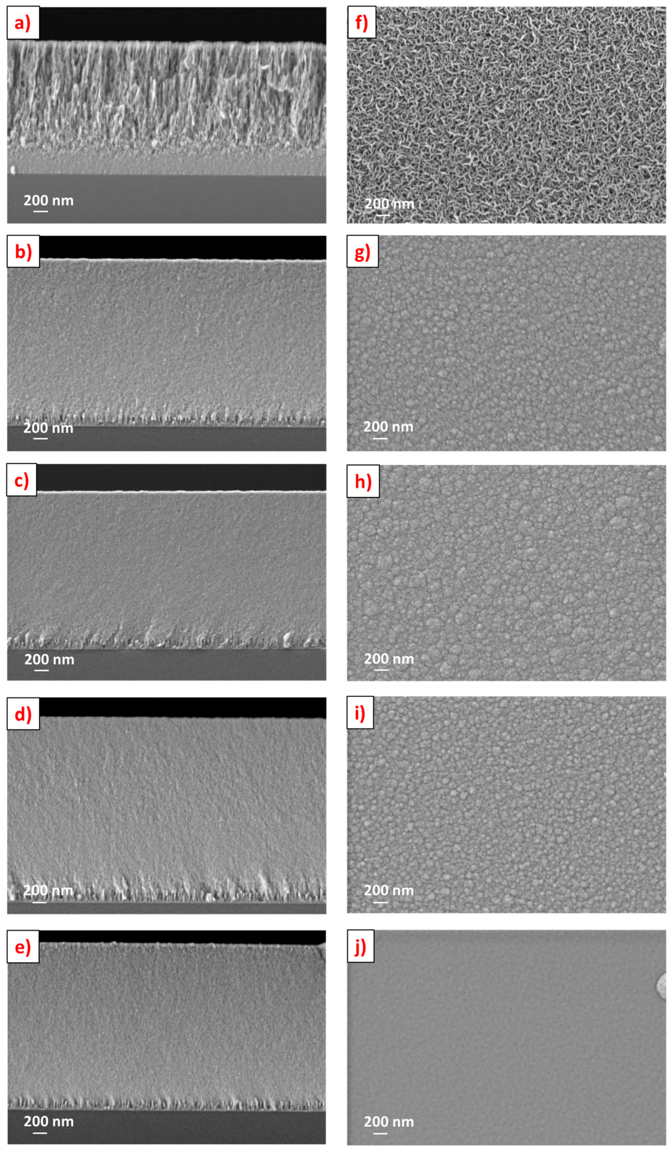
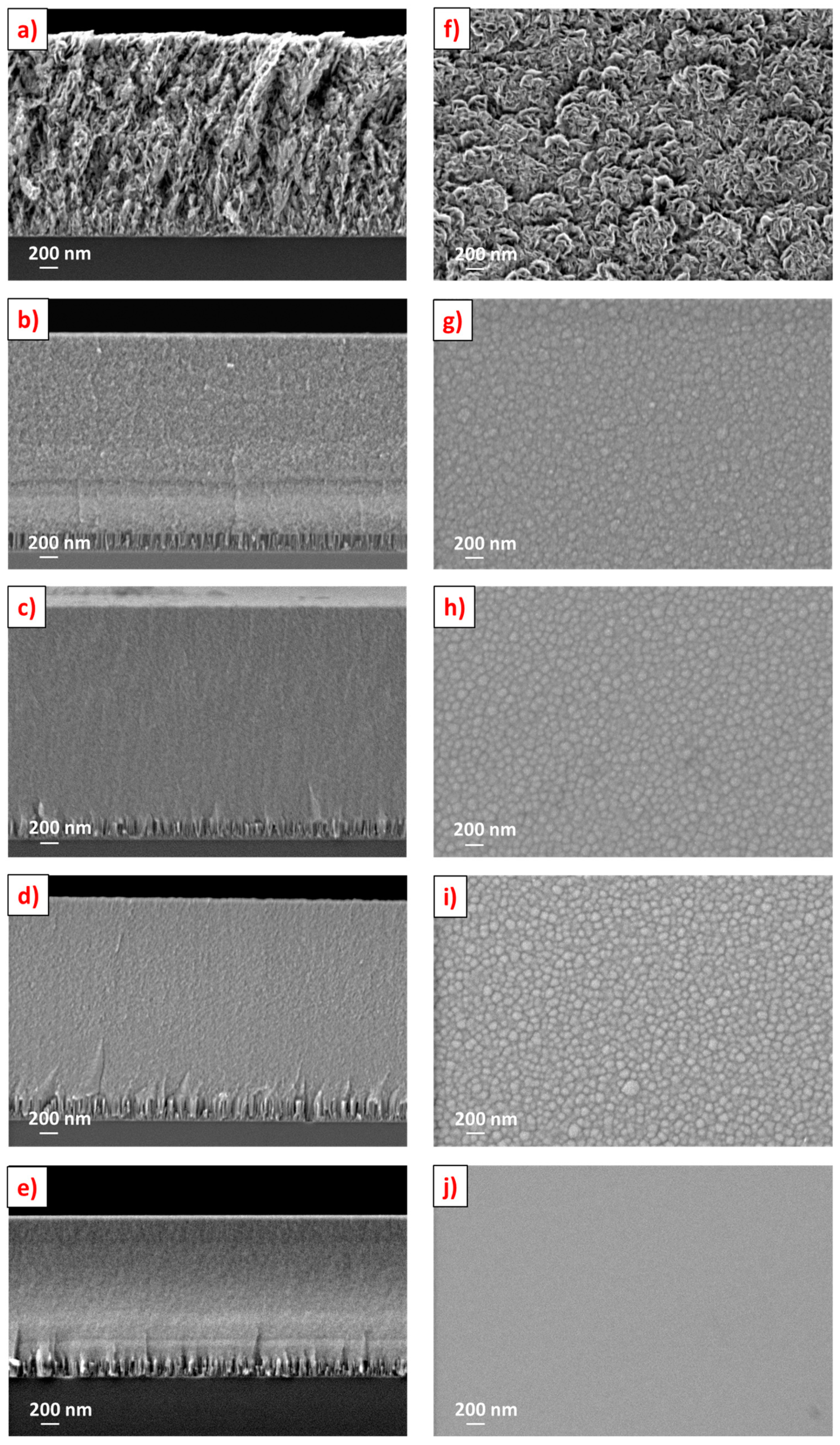
3.2. Fractured Cross-Section and Surface Morphology

Figure 1 and Figure 2 show the fractured cross-section and surface morphologies of cases 1 and 2 coatings, respectively, analysed by SEM. For MoSe2 coatings, Cr interlayers were not applied. The denser region near the substrate corresponds to the initial few minutes of deposition with the substrate bias leading to high preferential re-sputtering of Se and increased Mo content in this compact adhesion layer. In case 1, the sputtered MoSe2 coating (Figure 1a) displayed a columnar and porous cross-sectional morphology, with columns extending down to the Mo-rich layer. The porous nature of the MoSe2 coating was also evident from the sponge-like surface morphology (Figure 1f). When carbon was co-sputtered, the coatings became compact and columns disappeared (Figure 1b). Surface morphology micrographs corroborate the cross-sectional results: the sponge-like and porous surface features were replaced by a compact cauliflower type morphology after carbon addition (Figure 1g), due to limited surface mobility influencing the coating growth. No changes in the top and cross-sectional surface morphologies were observed after a further increase in the carbon content. The substrate bias contributed to a slight smoothening of the surface (Figure 1j), due to increased bombardment of growing coatings and thus providing increased adatom mobility and higher atomic coverage. The higher adatom mobility and, in turn, the increase of compactness is also facilitated by the elevated temperature at the surface of the growing film due to the substrate bias.
In case 2, the MoSe2 coating was again porous (Figure 2a) but it showed a strong contribution of dendritic growth as compared to DC sputtered one. Also, surface morphology did not show sponge-like features; instead, much wider features and grown-up crystals were observed (Figure 2f), which are related to the higher atomic mobility and low deposition rate of RF sputtering, thus allowing more time for the grains to nucleate at favorable sites and grow in size [47]. As expected, the addition of carbon led to an increase in compactness and a decrease of porosity similar to the case 1 coatings. For RF170, the sudden decrease of power to carbon targets after gradient layer deposition (500 W to 170 W), resulted in the formation of a visible layer in the fractured cross-section image (Figure 2b). For the biased coating (Figure 2j), smoothening of the surface was also observed as in case 1 coatings.
Our previous works [25,38], showed columns/dendrites in Mo–Se–C coatings. In this study, the lack thereof is related to the higher homogeneity achieved, very likely due to a continuously optimal bombardment of the growing coating with energetic particles. Furthermore, continuous confocal sputtering enhanced the substrate temperature, which is also contributing to the densification of the coatings [48]. With these conditions, even low carbon content addition to TMD coatings can give rise to a compact morphology (without columns). Globally comparing both DC and RF deposited coatings, similar morphologies and compactness were displayed. Based on the experience and reported literature [19,20], the enhanced compactness with high Se/Mo ratios achieved in this study can be ideal for mechanical and tribological properties.

3.3. Crystal Structure

3.3.1. X-ray Diffraction
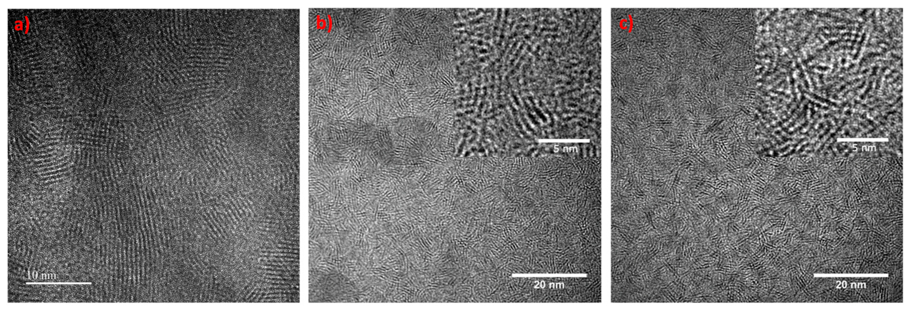
Grazing incidence X-ray diffraction analysis was used to assess the crystal structure of the coatings. Well-defined crystalline peaks typical of pure sputtered TMDs were visible in both XRD patterns for the pure MoSe2 coatings ICCD n° 087-2419 (Figure 3). Working in grazing incidence (3°), the peaks detected at ~13° correspond to the (002) planes inclined 5° in relation to the surface, which are closely parallel to the surface. These planes play a vital role in the easy shear properties of TMDs during sliding. At 30°–50°, peaks with an extended shoulder related to the (100) and (10 L) planes were observed. This feature was reported by Weise et al. [42], and is related to the turbostratic stacking of the (10 L) planes (L = 1, 2, 3, 4, …). The TMD peaks at ~13° and ~30°–50° were sharper and more well-defined in pure RF MoSe2 coating than for DC one, showing the higher degree of crystallinity of the former. In RF MoSe2 coating, (002) basal planes were dominant compared to (100) and (10 L) while, in DC, the inverse was observed. As the only main differences in the deposition of both coatings were the low deposition rates and the more ions impinging the growing coating in RF deposition—more time and enhanced adatom mobility and surface diffusion exists, allowing the atoms to relax at more favorable states, i.e., (002) preferential orientation [47]. More (002) contribution in RF sputtered MoSe2 is also in agreement with work of Muratore [49], who explained for MoS2 that the deposition rates of ~15 nm/min are required for achieving (002) basal planes and, in spite of the low desorption energies of (002) than (100), the former orientation can be achieved if there is some energetic ion bombardment (as it is in RF sputtering). It was further reported that having a deposition rate closer to ~15 nm/min provided an increased burial rate of the 2nd layer as compared to the desorption rates of the first layer thus promoting the (002) orientation. Muratore [49] added that an increase in (002)/(100) ratio enhanced the tribological properties. So, we expect that the pure RF coatings will provide better sliding properties then DC ones.
In both cases, carbon addition leads to structural changes and reduced crystallinity. Therefore, a broad peak at ~30°–50°, related to (100) and (10 L) planes of MoSe2 nanocrystals (<10 nm) appeared. Unlike other works on TMD-C coatings [20], (002) peaks were also detected for Mo–Se–C coatings, which can tentatively be explained by the lower percentage of carbon content and the higher Se/Mo ratio. Mutafov [50] claimed in his work on WSN coatings that (002) peaks were observed due to very low (i.e., less than 1.2) S/W ratio, but our results contradict that, as the decrease in Se/Mo ratio resulted in the vanishing of (002) peak (RF270(50V). Regardless, these peaks reveal the interesting presence of (002) planes with a possible positive impact on the tribological behavior of the coatings. As compared to pure coatings, the (002) peak in Mo–Se–C coatings is broader (in both cases), suggesting smaller sizes of MoSe2 crystallites (in agreement with TEM results shown later). Carbon disturbs the growth and impedes the formation of well-defined MoSe2 crystals. The addition of carbon, and the consequent decrease of Se/Mo ratio, also results in an increase in the interplanar distance confirmed by the (002) peak shift to lower angles (the shift is more evident in case 1 coatings). The decrease in Se/Mo ratio cannot explain the peaks shifts to a lower angle; however, carbon can become entrapped in the basal planes [51], causing the c lattice constant to increase. The increase in interplanar distances due to the incorporation of a 3rd element in the lattice has been reported by Rasamani [51] and Panigrahi [52], which is in agreement with our observations. The interplanar distances calculated from XRD diffractograms increased from ~0.69 nm (DC MoSe2) to ~0.75 nm (DC324) and from ~0.67 nm (RF MoSe2) to ~0.73 (RF170) in cases 1 and 2, respectively. Further increase in the carbon content increased this broadening of the peaks, shifts in (002) peaks position to lower angles, and an increase in the interplanar distances. The latter may reduce the Vander Waals forces between the basal planes and add a positive impact on the easy shearing properties of MoSe2. With the application of substrate bias, no effect on the X-ray diffraction patterns was observed in case 1 coatings. In case 2, (002) peaks were absent, very likely due to very low Se/Mo ratios (1.77 for DC540(50V) vs. 1.07 for RF270(50V)). Just like pure MoSe2 coatings, by similar reasons, the (002) peaks are more intense and sharper in C based MoSe2 (Mo–Se–C) RF coatings than in DC Mo-Se-C coatings, despite their lower Se/Mo ratio.

3.3.2. TEM Analysis

Transmission electron microscopy analysis was performed to investigate the shape and size of MoSe2 structures embedded in the carbon matrix (Figure 4). Although only selected HR-TEM images are shown for both cases, they are representative of all the coatings. Additionally, HR-TEM image of pure MoSe2 coating has been shown for microstructural comparison. The pure coatings depicted well-defined crystals of MoSe2 having long range ordering with crystal sizes much greater than C based coatings. Planes having orientation other than (002) basal planes were also detected, agreeing with XRD results. After the introduction of carbon, the micrographs in both cases showed MoSe2 nanoplatelets/nanograins randomly dispersed in the form of wires, separated by an amorphous phase. A total of 20 readings were taken for each sample at different locations to measure the average distance between the planes and the average number of stacked planes. The average distances were 0.691 ± 0.007 nm and 0.689 ± 0.009 nm for DC540 and RF270 coatings, respectively (a bit lower than the one from XRD i.e., 0.76 nm), which corresponds to the (002) planes of MoSe2 phase. Similarly, the average number of stacked planes were 4.6 ± 0.2 for DC540 coating and 4.0 ± 0.3 for RF270 coating, respectively. The length of the nanoplatelets was calculated at various regions with an average value of less than 10 nm, unlike pure coatings. Such small dimensions reflect the structural disturbance induced by the carbon incorporation in the pure coatings, hindering a suitable organization of the atoms during growth. TEM results agree with XRD observation (Section 3.3.1) concerning the small size of the crystals, which was the reason for the (002) XRD peak broadening for Mo–Se–C coatings. The interplanar distances measured from XRD and TEM are slightly different which can be probably explained by the very low thickness of TEM samples (25–30 nm) when compared to those analysed by XRD (~2 µm), leading to less stresses in the TEM samples in comparison to XRD ones.

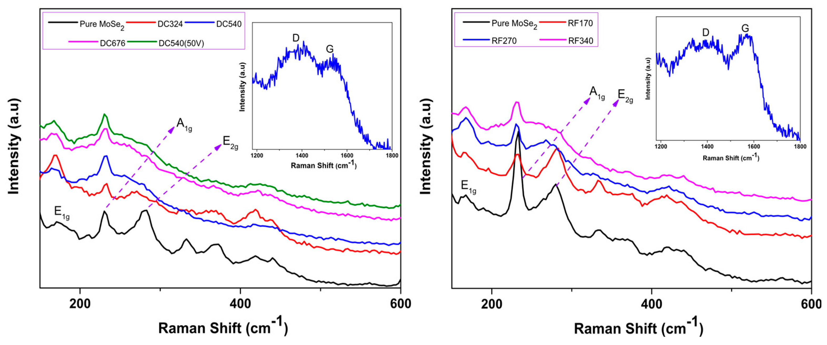
3.4. Chemical Bonding

Raman spectroscopy was performed on samples from cases 1 and 2 (Figure 5) to further study the phases present in the coatings, specially carbon. Well-defined peaks in positions typical of MoSe2 were obtained in all coatings, confirming XRD and TEM results. Furthermore, as expected, the addition of carbon resulted in a decrease in the intensity and an increase in the broadness of MoSe2 peaks.
Generally, for MoSe2 coatings, different in-plane (E1g and E2g) and out of the plane (A1g) vibrational modes appear [53]. In the deposited pure coatings, the E2g mode were significantly higher than the carbon-based coatings. The E2g mode became Raman inactive and the peak disappeared with the increments of carbon, due to the structural disturbance and decrease of crystallite size of MoSe2. These observations agreed with XRD and TEM results where the (100) and (10 L) peaks disappeared and crystallite sizes decreased. Moreover, carbon addition also restricted the MoSe2 bond vibrations due to increased compactness of the coating (Section 3.2), thus influenced the Raman response. Some other broad and barely visible peaks around ~350 and ~445 cm–1 corresponding to MoSe2 peaks were also observed. The E2g peak was also overlapping with the oxides (Mo-oxide) positioned at ~289 cm−1 [54,55].
Finally, the nature of the carbon phase was observed by analyzing D and G peaks. D peak was deconvoluted using the Lorentz line while for G peak Breit-Winger-Fano asymmetric line was used [56]. The peak positions after deconvolution indicated the presence of an amorphous carbon phase. It was also observed that the increase of carbon and decrease of Se/Mo ratio resulted in an increase in the intensity of the peaks related to amorphous carbon. ID/IG increased from 0.57 to 1.24 for DC324 to DC676 coatings, respectively and from 0.45 to 1.23 for RF170 to RF340 coatings, respectively. Only DC540(50V) was analyzed to study the influence of substrate bias on ID/IG ratio and peak positions; minor differences were observed. D and G peaks of only one Raman spectra from each case (having 22 at.% C) has been shown to be a representative of all coatings.

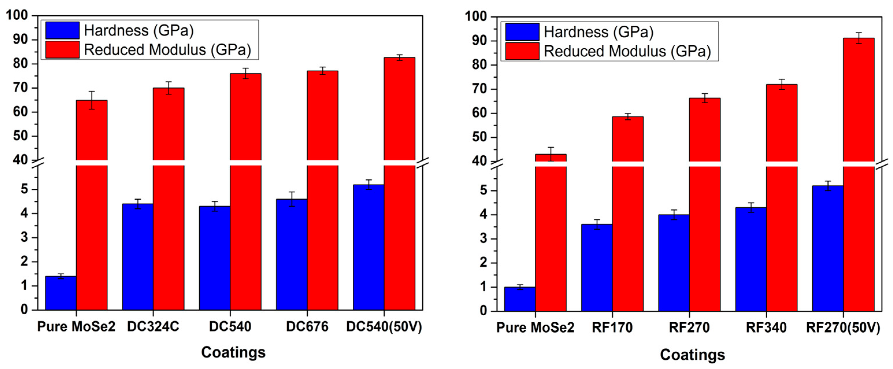
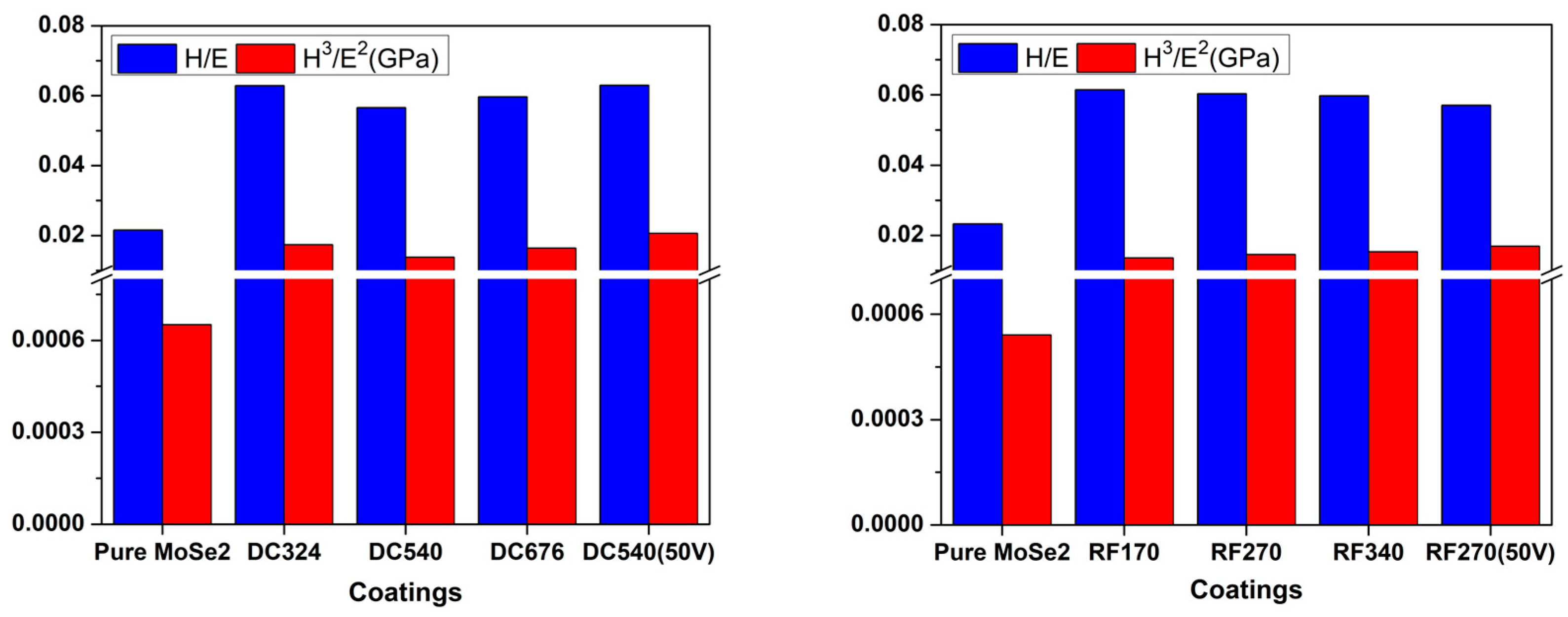
3.5. Mechanical Properties

Hardness and reduced modulus (E*) values of the coatings are shown in Figure 6. DC and RF pure MoSe2 coatings displayed hardness values of 1.4 GPa and 1.0 GPa, respectively. After carbon addition, all the coatings show higher hardness than MoSe2 due to the denser morphology, increased compactness, and presence of the carbon phase. Generally, in this study, the case 1 sputtered coatings outperformed case 2 ones due to more (002) crystallinity of the latter. Presence of higher number (002) planes, in the case 2 coatings, resulted in easy shearing properties and low hardness. Regardless, despite lower carbon content, all coatings showed higher hardness values than those achieved in previous works [20,37,38]. A hardness of ~3.2 GPa was reported for single target RF sputtered MoSe2 coatings deposited with 61 at.% of carbon [38], while here, a hardness of 4.6 GPa and 4.3 GPa was achieved for case 1 (DC676) and case 2 (RF340), respectively, with only ~25 at.% of carbon. In our recent study of separate target DC sputtering, we reported ~2.8 GPa for 50 at.% C coating deposited without substrate bias [37].
Moreover, the application of RF substrate bias resulted in the reduction of the Se/Mo ratio and the enhancement of density and compactness, resulting in the highest hardness (i.e., 5.2 GPa) for both DC540(50V) and RF270(50V) coatings; however, it must not be forgotten that the latter had very low Se/Mo ratio, which is not desirable.
It should be remarked that higher hardness values were achieved despite a much higher Se/Mo ratio (more contribution of the softer phase). Although the opposite trend was found in all works, i.e., the higher contribution of the softer phase reduces the hardness. The achieved results negate the claims of the literature [25,57], that ~50 at.% C is required for superior mechanical properties. The results also do not support the hypothesis of Mutafov et al. [50] which states that the presence of (002) planes parallel to the surface enhances the hardness, since the indenter applies load perpendicular to the parallel planes. If this was true, case 1 coatings should not show higher hardness than case 2 ones, since the latter presents higher crystallinity and higher (002) preferential orientation. We suggest that the high hardness is predominantly due to the higher compactness, the absence of columnar morphology, and the homogeneity of the coatings.
In both cases, the reduced elastic modulus followed similar trends as hardness, i.e., values increase for higher carbon contents. Parameters related to the elastic strain to failure H/E* [58] and fracture toughness H3/E*2 [59] are shown in Figure 7. These values are often related to the elastic energy storage and the wear resistance of the materials, with higher values considered to be beneficial for the final tribological performance [60].

4. Conclusions

This study provides solutions to optimize the synthesis and properties of Mo–Se–C coatings. Magnetron sputtered Mo–Se–C solid lubricant coatings were deposited by using different combinations of DC and RF magnetron sputtering. Low carbon content (~18 at.% to ~25 at.%) resulted in stoichiometric coatings, i.e., Se/Mo close to 2. The carbon addition and the application of substrate bias resulted in a slight reduction of the Se/Mo ratio with the exception of substrate biased RF coating. Only in the case of MoSe2 were differences in the morphology of DC and RF coatings achieved; with the addition of carbon and the application of substrate bias, both cases showed similar morphologies with a significant increase of the compactness and density. Unlike previous studies, and due to the continuous confocal sputtering, no columns or dendrites were observed in any of the Mo–Se–C coatings. Thus, this angled sputtering will be an interesting alternative to be explored for coating 3D parts. Also, differing from the literature, the (002) basal planes of MoSe2 phase were observed in the XRD diffractograms, even after carbon additions. The addition of carbon increased the (002) interplanar distances, which are expected to decrease the Vander Waals forces and enhance the easy shearing properties of MoSe2. HR-TEM images showed the presence of MoSe2 nanocrystals, with a dimension lower than 10 nm, embedded in an amorphous phase. Raman analysis confirmed the presence of MoSe2 crystalline material and detected an amorphous carbon phase. Mechanical properties of the coatings were enhanced after carbon additions due to the very high compactness to the coatings in the literature, despite the low carbon contents and high stoichiometry. In short, the results achieved with this deposition approach were much better than the literature and solved the issues of achieving a combination of low stoichiometry, high crystallinity, high hardness, and microstructure optimization for TMD-C solid lubricant coatings.

Author Contributions

Contributed to Synthesis, Testing, Data Analysis: T.B.Y., T.V. and P.S.; Writing: T.B.Y., Suggested and Supervised: A.C.; Contributing to Revising the Language of the Manuscript: T.P. and A.C.; Equipment and Facilities: T.P. and A.C. All authors have read and agreed to the published version of the manuscript.

Funding

This project is funded by the European Union’s Horizon2020 research and innovation programme under grant agreement No. 721642: SOLUTION.

Acknowledgments

The authors would also like to acknowledge the financial support from the projects: ATRITO-0 [co-financed via FEDER (PT2020) POCI-01-0145-FEDER-030446 and FCT (PIDDAC)], On-SURF [co-financed via FEDER (PT2020) POCI-01-0247-FEDER-024521] and CEMMPRE—UID/EMS/00285/2019 [co-financed via FEDER and FCT (COMPETE)], OPVVV grant Novel nanostructures for engineering applications No. CZ.02.1.01/0.0/0.0/16 026/0008396.

Conflicts of Interest

The authors declare no conflict of interest.

References

  1. Stachowiak, G.; Batchelor, A.W. Engineering Tribology; Butterworth-Heinemann: Oxford, UK, 2013. [Google Scholar]
  2. Aouadi, S.M.; Luster, B.; Kohli, P.; Muratore, C.; Voevodin, A.A. Progress in the development of adaptive nitride-based coatings for high temperature tribological applications. Surf. Coat. Technol. 2009, 204, 962–968. [Google Scholar] [CrossRef]
  3. Bhushan, B. Modern Tribology Handbook; CRC Press: Boca Raton, FL, USA, 2001. [Google Scholar]
  4. Jehn, H.A. Multicomponent and multiphase hard coatings for tribological applications. Surf. Coat. Technol 2000, 131, 433–440. [Google Scholar] [CrossRef]
  5. Vepřek, S. The search for novel, superhard materials. J. Vac. Sci. Technol. Vac. Surf. Film 1999, 17, 2401–2420. [Google Scholar] [CrossRef] [Green Version]
  6. Voevodin, A.A.; O’Neill, J.P.; Zabinski, J.S. WC/DLC/WS2 nanocomposite coatings for aerospace tribology. Tribol. Lett. 1999, 6, 75–78. [Google Scholar] [CrossRef]
  7. Fernandes, F.; Yaqub, T.B. A Cavaleiro, Influence of Ag additions on the structure, mechanical properties and oxidation behaviour of Cr-O coatings deposited by HiPIMS. Surf. Coat. Technol. 2018, 339, 167–180. [Google Scholar] [CrossRef]
  8. Renevier, N.M.U.; Hamphire, J.; Fox, V.C.; Witts, J.; Allen, T.; Teer, D.G. Advantages of using self-lubricating, hard, wear-resistant MoS2 -based coatings. Surf. Coat. Technol. 2001, 142, 67–77. [Google Scholar] [CrossRef]
  9. Savan, A.; Simmonds, M.C.; Huang, Y.; Constable, C.P. Effects of temperature on the chemistry and tribology of co-sputtered MoSx-Ti composite thin films. Thin Solid Films 2007, 489, 137–144. [Google Scholar] [CrossRef]
  10. Scharf, T.W.; Rajendran, A.; Banerjee, R.; Sequeda, F. Growth, structure and friction behavior of titanium doped tungsten disulphide (Ti-WS2) nanocomposite thin films. Thin Solid Films 2009, 517, 5666–5675. [Google Scholar] [CrossRef]
  11. Chien, H.; Ma, K.; Vattikuti, S.V.P.; Kuo, C.; Huo, C.; Chao, C. Tribological behaviour of MoS 2/Au coatings. Thin Solid Films 2010, 518, 7532–7534. [Google Scholar] [CrossRef]
  12. Lince, J.R. Tribology of co-sputtered nanocomposite Au/MoS 2 solid lubricant films over a wide contact stress range. Tribol. Lett. 2004, 17, 419–428. [Google Scholar] [CrossRef]
  13. Wahl, K.J.; Dunn, D.N.; Singer, I.L. Wear behavior of Pb—Mo—S solid lubricating coatings. Wear 1999, 230, 175–183. [Google Scholar] [CrossRef]
  14. Ye, M.; Zhang, G.; Ba, Y.; Wang, T.; Wang, X.; Liu, Z. Microstructure and tribological properties of MoS 2 + Zr composite coatings in high humidity environment. Appl. Surf. Sci. 2016, 367, 140–146. [Google Scholar] [CrossRef]
  15. Deepthi, B.; Barshilia, H.C.; Rajam, K.S.; Konchady, M.S.; Pai, D.M.; Sankar, J.; Kvit, A.V. Structure, morphology and chemical composition of sputter deposited nanostructured Cr-WS2 solid lubricant coatings. Surf. Coat. Technol. 2010, 205, 565–574. [Google Scholar] [CrossRef]
  16. Rigato, V.; Maggioni, G.; Boscarino, D.; Sangaletti, L.; Depero, L.; Fox, V.C.; Teer, D.; Santini, C. A study of the structural and mechanical properties of Ti-MoS2coatings deposited by closed field unbalanced magnetron sputter ion plating. Surf. Coat. Technol. 1999, 116, 176–183. [Google Scholar] [CrossRef]
  17. Teer, D.G.; Hampshire, J.; Fox, V.; Bellido-Gonzalez, V. The tribological properties of MoS2/metal composite coatings deposited by closed field magnetron sputtering. Surf. Coat. Technol. 1997, 94, 572–577. [Google Scholar] [CrossRef]
  18. Voevodin, A.A.; O’Neill, J.P.; Zabinski, J.S. Nanocomposite tribological coatings for aerospace applications. Surf. Coat. Technol. 1999, 116, 36–45. [Google Scholar] [CrossRef]
  19. Polcar, T.; Cavaleiro, A. Self-adaptive low friction coatings based on transition metal dichalcogenides. Thin Solid Films 2011, 519, 4037–4044. [Google Scholar] [CrossRef]
  20. Polcar, T.; Cavaleiro, A. Review on self-lubricant transition metal dichalcogenide nanocomposite coatings alloyed with carbon. Surf. Coat. Technol. 2011, 206, 686–695. [Google Scholar] [CrossRef]
  21. Hudec, T.; Mikula, M.; Satrapinskyy, L.; Roch, T.; Truchlý, M.; Jr, P.Š.; Huminiuc, T.; Polcar, T. Structure, mechanical and tribological properties of Mo-S-N solid lubricant coatings. Appl. Surf. Sci. 2019, 486, 1–14. [Google Scholar] [CrossRef]
  22. Prasad, S.V.; McDevitt, N.T.; Zabinski, J.S. Tribology of tungsten disulfide-nanocrystalline zinc oxide adaptive lubricant films from ambient to 500 °C. Wear 2000, 237, 186–196. [Google Scholar] [CrossRef]
  23. Characterization of air-annealed, pulsed laser deposited ZnO-WS2 solid film lubricants bt transmission electron microscopy. Thin Solid Films 1997, 305, 130–143. [CrossRef]
  24. Voevodin, A.A.; Zabinski, J.S. Nanocomposite and nanostructured tribological materials for space applications. Compos. Sci. Technol. 2005, 65, 741–748. [Google Scholar] [CrossRef]
  25. Polcar, T.; Evaristo, M.; Cavaleiro, A. Comparative study of the tribological behavior of self-lubricating W-S-C and Mo-Se-C sputtered coatings. Wear 2009, 266, 388–392. [Google Scholar] [CrossRef]
  26. Voevodin, A.A.; Muratore, C.; Aouadi, S.M. Hard coatings with high temperature adaptive lubrication and contact thermal management: Review. Surf. Coat. Technol. 2014, 257, 247–265. [Google Scholar] [CrossRef]
  27. Hilton, M.R. Fracture in MoS2 solid lubricant films. Surf. Coat. Technol. 1994, 68, 407–415. [Google Scholar] [CrossRef]
  28. Wang, D.-Y.; Chang, C.-L.; Ho, W.-Y. Microstructure analysis of MoS2 deposited on diamond-like carbon films for wear improvement. Surf. Coat. Technol. 1999, 111, 123–127. [Google Scholar] [CrossRef]
  29. Cao, H.; de Hosson, J.T.M.; Pei, Y. Effect of carbon concentration and argon flow rate on the microstructure and triboperformance of magnetron sputtered WS2/a-C coatings. Surf. Coat. Technol. 2017, 332, 142–152. [Google Scholar] [CrossRef]
  30. Cao, H.; Wen, F.; Kumar, S.; Rudolf, P.; de Hosson, J.T.M.; Pei, Y. On the S/W stoichiometry and triboperformance of WSxC(H) coatings deposited by magnetron sputtering. Surf. Coat. Technol. 2018, 365, 41–51. [Google Scholar] [CrossRef] [Green Version]
  31. Gu, L.; Ke, P.; Zou, Y.; Li, X.; Wang, A. Amorphous self-lubricant MoS2-C sputtered coating with high hardness. Appl. Surf. Sci. 2015, 331, 66–71. [Google Scholar] [CrossRef]
  32. Cai, S.; Guo, P.; Liu, J.; Zhang, D.; Ke, P. Friction and Wear Mechanism of MoS 2 / C Composite Coatings Under Atmospheric Environment. Tribol. Lett. 2017, 65, 1–12. [Google Scholar] [CrossRef]
  33. Xu, J.; Chai, L.; Qiao, L.; He, T.; Wang, P. Influence of C dopant on the structure, mechanical and tribological properties of rf-sputtered MoS2/aC composite films. Appl. Surf. Sci. 2016, 364, 249–256. [Google Scholar] [CrossRef]
  34. Donnet, C.; Erdemir, A. Historical developments and new trends in tribological and solid lubricant coatings. Surf. Coat. Technol. 2004, 181, 76–84. [Google Scholar] [CrossRef]
  35. Gustavsson, F.; Jacobson, S. Diverse mechanisms of friction induced self-organisation into a low-friction material—An overview of WS2tribofilm formation. Tribol. Int. 2016, 101, 340–347. [Google Scholar] [CrossRef]
  36. Polcar, T.; Gustavsson, F.; Thersleff, T.; Jacobson, S.; Cavaleiro, A. Complex frictional analysis of self-lubricant W-S-C/Cr coating. Faraday Discuss. 2012, 156, 383. [Google Scholar] [CrossRef] [PubMed] [Green Version]
  37. Bin, T.; Yaqub, T.; Vuchkov, M.; Evaristo, A. Cavaleiro, DCMS Mo-Se-C solid lubricant coatings—Synthesis, structural, mechanical and tribological property investigation. Surf. Coat. Technol. 2019, 378, 124992. [Google Scholar] [CrossRef]
  38. Polcar, T.; Evaristo, M.; Stueber, M.; Cavaleiro, A. Synthesis and structural properties of Mo-Se-C sputtered coatings. Surf. Coat. Technol. 2008, 202, 2418–2422. [Google Scholar] [CrossRef]
  39. Oliver, W.C.; Pharr, G.M. An improved technique for determining hardness and elastic modulus using load and displacement sensing indentation experiments. J. Mater. Res. 1992, 7, 1564–1583. [Google Scholar] [CrossRef]
  40. Martin, P.M. Handbook of Deposition Technologies for Films and Coatings: Science, Applications and Technology; Elsevier Inc.: Oxford, UK, 2009. [Google Scholar]
  41. Fominski, V.Y.; Nevolin, V.N.; Romanov, R.I.; Smurov, I. Ion-assisted deposition of MoSx films from laser-generated plume under pulsed electric field. J. Appl. Phys. 2001, 89, 1449–1457. [Google Scholar] [CrossRef]
  42. Weise, G.; Mattern, N.; Hermann, H.; Teresiak, A.; Ba, I.; Bru, W. Preparation, structure and properties of MoSx films. Thin Soli. 1997, 298, 98–106. [Google Scholar] [CrossRef]
  43. Grigoriev, S.N.; Fominski, V.Y.; Gnedovets, A.G.; Romanov, R.I. Experimental and numerical study of the chemical composition of WSex thin films obtained by pulsed laser deposition in vacuum and in a buffer gas atmosphere. Appl. Surf. Sci. 2012, 258, 7000–7007. [Google Scholar] [CrossRef]
  44. Dominguez-Meister, S.; Justo, A.; Sanchez-Lopez, J.C. Synthesis and tribological properties of WSex films prepared by magnetron sputtering. Mater. Chem. Phys. 2013, 142, 186–194. [Google Scholar] [CrossRef] [Green Version]
  45. Betz, G.; Wehner, G.K. Sputtering of Multicomponent Materials. In Sputtering by Particle Bombardment II; Springer: Berlin/Heidelberg, Germany, 1983; pp. 11–90. [Google Scholar] [CrossRef]
  46. Swann, S. Magnetron sputtering. Phys. Technol. 1988, 19, 67–75. [Google Scholar] [CrossRef]
  47. Tan, S.; Zhang, X.; Wu, X.; Fang, F.; Jiang, J. Comparison of chromium nitride coatings deposited by DC and RF magnetron sputtering. Thin Solid Films 2011, 519, 2116–2120. [Google Scholar] [CrossRef]
  48. Kelly, P.J.; Arnell, R.D. Magnetron sputtering: A review of recent developments and applications. Vacuum 2000, 56, 159–172. [Google Scholar] [CrossRef]
  49. Muratore, C.; Voevodin, A.A. Control of molybdenum disulfide basal plane orientation during coating growth in pulsed magnetron sputtering discharges. Thin Solid Films 2009, 517, 5605–5610. [Google Scholar] [CrossRef]
  50. Mutafov, P.; Evaristo, M.; Cavaleiro, A.; Polcar, T. Structure, mechanical and tribological properties of self-lubricant W-S-N coatings. Surf. Coat. Technol. 2015, 261, 7–14. [Google Scholar] [CrossRef]
  51. Rasamani, K.D.; Alimohammadi, F.; Sun, Y. Interlayer-expanded MoS 2. Mater. Today 2017, 20, 83–91. [Google Scholar] [CrossRef]
  52. Panigrahi, P.K.; Pathak, A. Aqueous Medium Synthesis Route for Randomly Stacked Molybdenum Disulfide. J. Nanoparticles. 2013, 23, 1–10. [Google Scholar] [CrossRef] [Green Version]
  53. Tonndorf, P.; Schmidt, R.; Böttger, P.; Zhang, X.; Börner, J.; Liebig, A.; Albrecht, M.; Kloc, C.; Gordan, O.; Zahn, D.R.T.; et al. Photoluminescence emission and Raman response of monolayer MoS2, MoSe2, and WSe2. Opt. Express 2017, 21, 4908–4916. [Google Scholar] [CrossRef]
  54. Gustavsson, F.; Jacobson, S.; Cavaleiro, A.; Polcar, T. Frictional behavior of self-adaptive nanostructural Mo-Se-C coatings in different sliding conditions. Wear. 2013, 303, 286–296. [Google Scholar] [CrossRef] [Green Version]
  55. Sekine, T.; Izumi, M.; Nakashizu, T.; Uchinokura, K.; Matsuura, E. Raman scattering and infrared reflectance in 2H-MoSe2. J. Phys. Soc. Jpn. 1980, 49, 1069–1077. [Google Scholar] [CrossRef]
  56. Ferrari, A.C.; Robertson, J. Interpretation of Raman spectra of disordered and amorphous carbon. Phys. Rev. B. 2000, 61, 95–107. [Google Scholar] [CrossRef] [Green Version]
  57. Polcar, T.; Evaristo, M.; Cavaleiro, A. The tribological behavior of W-S-C films in pin-on-disk testing at elevated temperature. Vacuum 2007, 81, 1439–1442. [Google Scholar] [CrossRef]
  58. Leyland, A.; Matthews, A. On the significance of the H/E ratio in wear control: A nanocomposite coating approach to optimised tribological behaviour. Wear 2000, 246, 1–11. [Google Scholar] [CrossRef]
  59. Musil, J.; Kunc, F.; Zeman, H.; Poláková, H. Relationships between hardness, Young’s modulus and elastic recovery in hard nanocomposite coatings. Surf. Coat. Technol. 2002, 154, 304–313. [Google Scholar] [CrossRef]
  60. Charitidis, C.A.; Logothetidis, S. Effects of normal load on nanotribological properties of sputtered carbon nitride films. Diam. Relat. Mater. 2005, 14, 98–108. [Google Scholar] [CrossRef]
Figure 1. Scanning electron microscopy micrographs of the cross-section morphologies: (a) Pure MoSe2, (b) DC324, (c) DC540, (d) DC676, (e) DC540(50V) and their respective top surface morphologies: (f) Pure MoSe2, (g) DC324, (h) DC540, (i) DC676, (j) DC540(50V).
Coatings 10 00133 g001
Figure 2. Scanning electron microscopy micrographs of the cross-section morphologies: (a) Pure MoSe2, (b) RF170, (c) RF270, (d) RF340, (e) RF270(50V) and their respective top surface morphologies: (f) Pure MoSe2, (g) RF170, (h) RF270, (i) RF340, (j) RF270(50V).
Coatings 10 00133 g002
Figure 3. X-ray diffraction patterns of the coatings (case 1-left and case 2-right).
Coatings 10 00133 g003
Figure 4. Transmission electron microscopy images of the (a) Pure MoSe2, (b) DC540 and (c) RF270 coatings.
Coatings 10 00133 g004
Figure 5. Raman spectra of coatings from case 1 (left) and case 2 (right)-inset in left figure is showing D and G peaks.
Coatings 10 00133 g005
Figure 6. Hardness and reduced modulus of the coatings (case 1-left and case 2-right).
Coatings 10 00133 g006
Figure 7. H/E* and H3/E*2 of the coatings (case 1-left and case 2-right).
Coatings 10 00133 g007
Table 1. Main deposition parameters, thickness and deposition rates of the coatings.
CoatingMoSe2 Power (W)Carbon Power (W)Bias (V)Time (min)Thickness (µm)Deposition Rate (nm/min)
Case 1
DC Pure MoSe2270--601.932
DC324270324-1102.422
DC540270540-1102.321
DC676270675-1102.624
DC540(50V)270540501102.220
Case 2
RF Pure MoSe2270--1202.319
RF170270170-1702.515
RF270270270-2102.613
RF340270340-1702.615
RF270(50V)270270501701.911
Table 2. Chemical composition and Se/Mo of the coatings.
CoatingsC (at.%)Mo (at.%)Se (at.%)O (at.%)Se/Mo
Case 1
DC32417.7 ± 0.427.1 ± 0.254.2 ± 0.31.0 ± 0.22.00
DC54021.4 ± 0.326.2 ± 0.151.3 ± 0.21.1 ± 0.11.96
DC67625.1 ± 0.525.2 ± 0.248.4 ± 0.41.3 ± 0.11.92
DC540(50V)27.2 ± 0.426.1 ± 0.546.2 ± 0.50.5 ± 0.11.77
Case 2
RF17017.9 ± 0.328.2 ± 0.252.4 ± 0.41.5 ± 0.11.86
RF27021.7 ± 0.327.3 ± 0.149.4 ± 0.21.6 ± 0.11.81
RF34024.7 ± 0.426.6 ± 0.247.7 ± 0.21.0 ± 0.21.79
RF270(50V)35.2 ± 0.630.9 ± 0.433.1 ± 0.60.8 ± 0.21.07

