Article

Effect of Graphite Content on the Conductivity, Wear Behavior, and Corrosion Resistance of the Organic Layer on Magnesium Alloy MAO Coatings

1
Shandong Provincial Key Laboratory of High Strength Lightweight Metallic Materials, Advanced Materials Institute, Qilu University of Technology (Shandong Academy of Sciences), Jinan 250014, China
2
Shandong Engineering Research Centre of Lightweight Automobiles Magnesium Alloys, Advanced Materials Institute, Qilu University of Technology (Shandong Academy of Sciences), Jinan 250014, China
*
Authors to whom correspondence should be addressed.
These authors contributed equally to this work.
Coatings 2022, 12(4), 434; https://doi.org/10.3390/coatings12040434
Submission received: 4 March 2022 / Revised: 21 March 2022 / Accepted: 22 March 2022 / Published: 24 March 2022
(This article belongs to the Special Issue Surface Electrochemistry: Corrosion and Electrode Materials)

Abstract

:
To impart electrical conductivity on magnesium alloy micro-arc oxidation coatings, a graphite/epoxy conductive layer was prepared on the surface of a ceramic layer in this work, focusing on wear behavior and corrosion resistance of the coating. At a graphite weight of 80 wt%, the square resistance of the coating decreased to 217.6 kΩ/□, and it exhibited good resistance. Combined with the distribution of graphite particles in the coating and the change in surface resistance, we determined that the conductive mechanism of the coating occurred through quantum tunneling when the graphite content was 60 wt%. When the graphite content increased from 60 to 80 and 100 wt%, the formation of conductive paths on the surface of the coating further improved the conductivity. The hardness of the organic coatings was positively related to the graphite content. Analysis of the wear scars and wear debris after dry friction and wear testing showed that the wear forms of the coating consisted of abrasive wear when the graphite content was in the range of 20–40 wt%. When the graphite content was in the range of 60–100 wt%, the wear forms of the coating consisted of abrasive wear and peeling wear.

1. Introduction

As lightweight metallic materials, magnesium alloys have high specific strength and special damping and functional electromagnetic properties [1,2]. Magnesium alloys are considered to be one of the most promising materials in the 21st century for the rapid development of lightweight products [3]. However, magnesium alloys have certain disadvantages such as poor corrosion and wear resistance [4,5]. Currently, surface phosphating [6,7,8], chemical conversion [9], anodic oxidation, micro-arc oxidation (MAO) [10,11], vapor deposition [12], and polymer coatings are effective surface modification methods of magnesium alloys in industrial engineering. Among these, MAO has become an important environment-friendly process for the surface protection of magnesium alloys to create high-strength ceramic coatings with excellent hardness [13].
At present, most reports focus on optimizing the pores and defects on the surface of the ceramic layer by Graphene oxide (GO), such as MAO/GO composite coatings [14], MAO/HA/GO) coatings and GO/MgAl-LDH/MAO coatings [15,16]. These composite coatings could provide an effective protection on the surface of the ceramic layer, and the corrosion resistance of the composite layer is significantly improved compared with the single MAO Coatings However, the insulation characteristics of MAO have not became significantly better, which limits the application of this technology for electromagnetic shielding. Therefore, magnesium alloy surfaces treated with MAO must be further optimized for electrical conductivity to promote the application of the alloy and MAO in this field. Typical surface conductive treatment technologies for ceramic layers include surface metallization [17,18,19,20] include conductive polymer coatings [21,22], vapor deposition [23,24], and magnetron sputtering [25,26]. After surface metallization, the surface will exhibit good electrical conductivity; however, internal galvanic corrosion will inevitably form, reducing the corrosion resistance of the ceramic layer [27]. Vapor deposition and magnetron sputtering cannot be quickly applied on a large industrial scale. Thus, conductive polymer coatings may be a better choice, as they offer high compactness and good weather resistance. Conductive polymer coatings can be generally classified into two types: intrinsic conductive and filled conductive coatings [28,29]. Intrinsic coatings generally include polyaniline, polypyrrole, and polyacetylene, while filled coatings are mainly composed of a matrix resin and conductive filler particles. The conductive filler particles can be divided into carbon-based, metal-based, and conductive metal oxide-based particles. Epoxy resins, phenolic resins, and acrylate can be used as the matrix resin, and among these, epoxy resins have advantages of low shrinkage, high cohesion, and a high bonding strength [30].
The stability of carbon based conductive fillers is higher than that of metal based fillers. Conductive carbon black (mainly acetylene carbon black) has generally been used to strengthen rubber and is the main additive in conductive silicone rubbers that require low conductivity [31]. Graphene has a high aspect ratio, specific surface area, excellent thermal, optical, and electrical properties, and can form an uninterrupted conductive network in a polymer matrix [32]. Swetha et al. [33] dispersed graphite nanosheets (GNPs) using two techniques consisting of a three-roll mill (3RM) and ultrasound combined with high-speed shear mixing (Soni_hsm). Then, the researchers prepared GNP/epoxy-based polymer nanocomposites and found that the conductivity of the composite material following 3RM technology was three orders of magnitude higher than that of the composite material prepared via Soni_hsm, reaching 1.8 × 10⁻³ S/m after property testing. Meschi Amoli et al. [32] modified graphene nanosheets with SDS to prepare an epoxy adhesive (ECA), showing that the addition of SDS-modified graphene reduced the permeation threshold of silver content from 40 wt% to 10 wt%. However, the inhomogeneous dispersion of graphene layers within the matrix caused by high aspect ratio, hydrophobicity and π-π interactions and high cost reduced the inherent application advantages of graphene [34]. Therefore, graphite has become a more suitable choice due to its good thermal conductivity, small thermal expansion coefficient, stable chemical properties, and smaller influence on the fluidity of the system [35]. Especially, Mg has its unique properties in graphitized structures, it has been reported that Mg-graphene/graphite electrodes can be used for detection of nucleotide polymorphisms of single DNA molecules resulting in early detection of diseases induced by gene overexpression [36,37].
Graphite has generally been mixed with other conductive particles or pretreated as a conductive medium in the system to obtain better electrical conductivity [38]. However, the influence of graphite without pretreatment and as a single conductive medium on the properties of conductive coatings requires further assessment. Although the MAO technology can improve the wear resistance of the Mg matrix, there have been relatively few studies on the friction and wear properties of the conductive coatings on a ceramic layer. The effect of the conductive particle filling amount on the friction and wear behavior of the coating also requires research for conductive coatings. Therefore, in this study, graphite was used as a single doped conductive particle without any pretreatment, while epoxy resin was used as the matrix resin. Then, the obtained graphite-epoxy conductive coating was blended with additives, and the ceramic layer after MAO was coated with the graphite-epoxy conductive coating to obtain a composite layer, and its properties were subsequently characterized.

2. Experimental Section

2.1. Materials

The base material consisted of pure magnesium (purity ≥ 99.95%, Dongguan Dizhong Metals Co., Ltd., Dongguan, China), which was processed into a circular sample with a size of φ = 20 mm and d = 3 mm using a wire cutting. Then, it was polished with 240#, 800#, and 2000# water-based SiC sandpaper, dried, stored after washing with ionic water, and ultrasonically cleaned in absolute ethanol for 5 min. Epoxy resin (E44) was selected as the matrix resin, while graphite powder (Shanghai-style reagent, 5000 mesh, Shanghai, China) was used as the conductive filler particles. In addition, anhydrous ethanol and an SCA (KH-550, Shanghai, China) were used as the auxiliary agent, and the curing agent was triethylene tetramine (TETA, Shanghai, China).

2.2. Preparation of the MAO Coating

The MAO samples were prepared with a JCL-AOM7DS power supply (Chengdu Jinchuangli Science & Technology Co., Ltd., Chengdu, China). The magnesium alloy substrate was connected to the electrode with the aluminum wire as the anode and the stainless steel plate as the cathode, forming a circuit in the electrolyte. The MAO electrolyte was composed of 3 g/L of NaOH, 10 g/L of Na2SiO3, and 1.5 g/L of NaF, and the solvent consisted of deionized water. MAO was performed in constant voltage mode, where the positive phase voltage was 380 V, the negative phase voltage was 90 V, the duty cycle was 10%, the frequency was 500 Hz, and the oxidation time was 5 min. The MAO specimens were washed by ultrasonication for 5 min (Fisher brand S40, Schwerte, Germany) and dried with hot air for later use.

2.3. Preparation of the Composite Coatings

Epoxy resin was diluted with anhydrous ethanol, and then, graphite powder and SCA were added in turn, evenly stirred, and the mixture was allowed to stand in a water bath (60 °C) for a period of time to allow any bubbles to escape. After adding the curing agent, a coater (KTQ-III, unit scale 10 μm, Guangzhou, China) was used to coat the sample surface with a coating thickness of 80 μm, which was then cured at a curing temperature of 60 °C for 1 h. The specific initial proportions of each part are shown in Table 1. The influence of graphite content on the coating properties was explored using the variable control method while keeping the components unchanged. In this study, five groups of samples with graphite content values of 20, 40, 60, 80, and 100 were prepared.

2.4. Microstructure and Surface Roughness Characterization

A scanning electron microscope (SEM, Zeiss Evoma10, Shanghai, China) equipped with an energy dispersive spectrometer (EDS, Oxford X-Max50, Oxford, UK) was used to examine the surface morphologies of the different specimens. These included the MAO coatings and cross-sections after application of the different graphite-epoxy Coatings The thickness of the coating was determined by SEM observations of the longitudinal section of each specimen. A roughness tester (TR211, Bdch Co., Ltd., Beijing, China) was used to determine the sample surface roughness (Ra). Each specimen was measured three times and the average value was used.

2.5. Hardness, Friction and Wear Test

The Surface hardness of the sample was measured by digital brinell hardness tester (320HBS-3000, Laizhou Huayin Testing Instrument Co., Ltd., Yantai, China). The indenter size of 5 mm and the holding force of 125 N were selected to be the test parameters. The holding time of test force was 15 s. To ensure the accuracy of the data, each sample was tested with six points on the surface. A rotary reciprocating friction and wear tester (MXW-1, Jinan Yihua Tribology Testing Technology Co., Ltd., Jinan, China) was used to conduct dry friction experiments on the Coatings In the experiments, a reciprocating module was selected and 45 stainless steel was used as the indenter, where the test force was 10 N, the frequency was 10 Hz, the displacement was 3000 μm, the maximum friction force was 100 N, and the friction and wear time was 20 min. After the experiment, the wear debris was collected. Then, the wear scars on the sample surfaces were ultrasonically cleaned with anhydrous ethanol, dried, and stored for later observation.

2.6. Electrochemical and Electrical Conductivity Tests

Potentiodynamic polarization (PDP) and impedance curves were obtained using an electrochemical workstation (Shanghai CH Instrument CHI660E, Shanghai, China) for the specimens plated with different complexing agent contents in 3.5 wt% NaCl solution at room temperature. The measurements utilized a three-electrode electrochemical cell, namely, a saturated calomel electrode (SCE) for the reference electrode, a platinum electrode for the counter electrode, and the specimen served as the working electrode. Before each measurement, the electrodes were immersed in the NaCl solution for 2000 s for stabilization. Then, the PDP curves were measured from low to high at a scan rate of 1 mV/s, and the electrochemical data were derived from the PDP curves via Tafel extrapolation. The square resistance (R□) values of the specimens with different surfaces were obtained using a four-point probe meter (Guangzhou Four Probes Tech RTS-9, Guangzhou, China). An HP-504 type four-point probe was used in the test, and the distance between the probes was 1 mm. Each specimen was measured three times, and the average value was obtained.

3. Results and Discussion

3.1. Coating Morphology and Roughness

Figure 1 shows the surface morphologies of the MAO coatings and the polymer layers. As shown in the figure, the pores inside the MAO coating exhibited a good sealing effect after the conductive layer was applied. There were no obvious graphite particles on the surface of the organic layer with graphite content of 20 and 40 wt% due to the precipitation of air bubbles during the curing reaction. Thus, the coating surface was generally flat and contained large holes, and some of the holes had obvious protrusions on the edges. As shown in Figure 3a,b, the graphite particles were mainly distributed in the middle and bottom of the coating, and almost no conductive particles were found on the surface. When the particle content reached 60 wt%, the holes on the coating surface were replaced by pits, and noticeable graphite particles were observed after amplification. When the graphite content in the coating increased to 80 and 100 wt%, the outlines of the flake graphite particles could be clearly observed on the organic layer surface, the particles were connected to each other in the coating, and the surface was relatively rough.
Figure 2 shows the variation trend of the coating surface roughness (Ra) with graphite content, showing that it was positively correlated with added graphite content overall. However, the Ra of the 40 wt% sample was lower than that of the 20 wt% sample, which can be explained from Figure 3a,b. The surface of the coating prepared with 20 wt% of graphite partially protruded as the internal bubbles did not separate out on time during curing, and the local surface fluctuations caused by the shrinkage of the epoxy resin during curing were relatively large. Therefore, its surface roughness was higher than that of the 40 wt% sample. Failure to separate out the bubbles on time and shrinkage during the curing process were more obvious in the single epoxy coating without graphite. However, this also showed that the addition of graphite particles could effectively reduce the curing shrinkage of the matrix resin. From the cross-sections shown in Figure 3, it can be seen that there were noticeable micro-cracks in the coatings with different graphite content, because the coatings generated internal stresses during the curing process. The internal stresses were mainly caused by glassy shrinkage upon cooling, which was dependent on the crosslinking density of the system but independent of the type of curing agent.

3.2. Hardness Friction and Wear Analysis of the Coating

Figure 4 shows the hardness variation of samples with different surface states. Due to the existence of ceramic coating on the surface of MAO specimen, the hardness value was significantly higher than that of bare magnesium matrix. For samples with organic layer, the hardness value of 20–80 wt% was lower than the magnesium matrix. This was because at the curing temperature of 60 °C, the matrix epoxy resin had residual parts that were not fully cured inside the coatings, and these residual parts would act as the toughening agent of the coatings, which improved the tensile elongation, while reducing the strength and hardness. The surface hardness of organic coatings increased with the increase of graphite content. Firstly, the addition of graphite particles made the thermal conductivity of the coatings better, so there was less and less residue without curing, and the strength of the coatings got recovered. Secondly, after the coatings was cured, there were more and more graphite particles formed a strong physical bond with the epoxy matrix on the surface. These graphite particles would share a portion of the load applied to the coatings before being crushed and broken in the whole test. However, too many graphite particles in the coating reduced the crosslinking density of epoxy solvent. So that the surface hardness was lower than that of MAO when the graphite content reached 100 wt%. There were more gaps between particles, making it easier to be fracturing under the action of load. So the hardness test performance was not as good as the ceramic Coatings.
Figure 5 shows the friction coefficient curves of the matrix (Figure 5a) and the organic layer (Figure 5b). The friction coefficient curve of the magnesium matrix fluctuated greatly, because the magnesium alloy had poor wear resistance, and it produced cutting wear on the surface at the initial stage of friction. Therefore, more debris was generated, and some of the debris was squeezed to the edges of the wear scar, while other debris caused damage to the matrix as friction progressed. As a result, the wear scar morphology of the magnesium alloy substrate after friction and wear (Figure 6a) mainly consisted of wide furrows and large spalling pits. The friction coefficient curve of the ceramic layer was relatively stable during the initial stage, but it started to fluctuate as friction continued. This was due to three-body abrasion caused by the debris, which was generated by the ceramic layer during the friction process. In addition, the friction coefficient curve fluctuated after the ceramic layer was worn away and exposed the matrix. The wear scar morphology of the ceramic layer was mainly dominated by narrow furrows (Figure 6b), with a few spalling pits.
The friction coefficient of the coating became stable for the samples coated with an organic layer. With a small amount of graphite content (20–60 wt%), the coating surface mainly consisted of the cured resin, which was relatively flat; thus, the friction coefficient was small and stable (Figure 5b). The wear morphology (Figure 6c,d) mainly consisted of furrow morphology. When the graphite weight increased to 60 wt%, a flattened area in the middle of the wear scar was found in addition to the furrow characteristics of the edge (Figure 6e). When the graphite content in the coating reached 80 wt%, the friction coefficient increased, due to the exposed graphite particles on the surface of the coating and the unevenness; thus, the curve gradually decreased and became stable. We observed that the intermediate surface of the wear scar (Figure 6f) was flat, because the wear debris was compacted on the surface of the material by the reciprocating indenter, which also indirectly led to the decrease in the friction coefficient curve during the later stage of friction. At 100 wt%, the friction coefficient of the coating decreased again, this time because the graphite content in the coating was too high, resulting in poor viscosity and fluidity before coating. After curing, the structural strength of the coating was not high and the connection strength with the substrate was low. In addition, most of the debris generated during the friction process was pressed by the indenter on the surface of the wear scar, making it difficult to collect.
Figure 7 shows the wear debris morphology of each sample after friction and wear. According to EDS, the composition of the magnesium matrix wear debris mainly consisted of Mg, and the wear debris morphologies included strip-shaped, granular, and delaminated debris. The strip-shaped chips were mainly produced by cutting wear, which were then crushed during the friction process, forming granular chips. These chips subsequently wore down the substrate along with the indenter, as the delamination debris was mainly brittle and caused exfoliation due to the crushing of the matrix under the action of friction loading. This indicated that the wear mechanism of the magnesium alloy consisted of cutting wear, abrasive wear, and delamination wear. For the MAO layer, the wear debris mainly consisted of granular powder, along with a massive peeling layer, while the granular powder was mainly composed of MgO, and the element in the block exfoliation was mainly composed of Mg, which indicated that the wear mechanism of the MAO layer was mainly abrasive wear. The wear debris of the organic layer was mainly composed of massive debris. The EDS results indicated that the organic layer wear debris was mainly composed of C and O, and the peak value of O gradually decreased with increasing graphite content, and no Mg was detected in the wear debris in each group of samples, indicating that the organic layer effectively protected the matrix. This massive debris became larger with increasing graphite content, the wear scar morphology was mainly furrow (Figure 6c,d) with low graphite content (20, 40 parts), and the wear mechanism was abrasive particle wear. When the graphite weight increased to 60 wt%, the surface of the wear scar (Figure 6e) started to exhibit exfoliated areas. When the graphite content increased, the exfoliation area after friction and wear increased, indicating that the increase in graphite content changed the wear mechanism of the coating from single abrasive wear to abrasive wear and delamination wear.

3.3. Conductivity of the Coating

Figure 8 shows the square resistance (R□) values of the composite layers, showing that the square resistance of the coating decreased with increasing graphite content.
We observed that the coatings had excellent electrical conductivity when the graphite content reached 80 and 100 wt%. When the graphite content in the system reached 40 wt%, the coating had no electrical conductivity, as shown by the coating section (Figure 3a,b) after it was cured on the sample surfaces. The graphite particles that served as a conductive medium were distributed in the middle and bottom of the coating, and the surface was almost undistributed. Thus, the insulating organic layer completely covered the graphite particles, and the surface of the coating could not form a conductive path and quantum tunneling could not function. As a result, the surface of the coating could not conduct electricity at this time. With 60 wt% graphite content, the square resistance of the coating was 829 kΩ/□, indicating that the percolation threshold of the graphite/epoxy conductive coating was between 40 and 60 wt%. Although the amount of graphite particles distributed on the surface of the coating gradually increased, there were no tight connections between the particles (Figure 3c). At this point, the barrier that prevented electrons from moving became weaker or even disappeared, and the coating had a certain conductivity due to the tunneling effect (Figure 9). As the graphite content continued to increase, the graphite particles on the surface of the coating became denser, and the distances between the conductive particles inside the coating decreased or even disappeared. As a result, they gradually formed a conductive path, and along with the synergistic effect of tunneling, the square resistance of the coating significantly decreased (80 wt%). Thus, the square resistance of the coating was reduced to 14 kΩ/□ when the graphite content reached 100 wt%.

3.4. Electrochemical Properties

Figure 10 shows the Nyquist, Bode, and polarization curves of the Mg, MAO, 80, and 100 wt% graphite content samples, the larger low-frequency impedance modulus |Z| in the Bode diagram indicates an excellent corrosion resistance. The impedance modulus values of the 80 wt% coating samples in Figure 10d were higher than those of the other three groups of samples, especially the 100 wt% samples, which had a |Z| that was even lower than that of the MAO sample. The PDP curve is shown in Figure 9f, and Table 2 shows the parameters after fitting the polarization curves of the four groups of samples. The corrosion current (Icorr) of the MAO samples decreased by two orders of magnitude compared to that of the magnesium matrix, indicating that MAO treatment could effectively protect the matrix. Compared to the substrate, the corrosion potential (Ecorr) of the 80 wt% samples shifted forward by 1.224 V, and these samples had the highest polarization resistance value, which further improved the corrosion resistance of the substrate. However, when the graphite content reached 100 wt%, the compactness and viscosity of the coating significantly decreased due to the large number of graphite particles in the coating. This made it easier for the corrosive medium to penetrate into the matrix, and as a result, Ecorr and Icorr showed poor performance.
The 80 and 100 wt% coatings endowed the insulating ceramic layer with conductivity, and the corrosion resistance of the 80 wt% composite coating greatly improved compared to MAO. However, the conductivity of the 100 wt% sample coating was superior, and its corrosion resistance was lower than that of the 80 wt% samples. In addition, during the coating preparation and coating processes, the fluidity and viscosity of the coating deteriorated with increasing graphite content in the coating. When the graphite content in the coating reached 100 wt%, the coating almost lost fluidity, which not only made particle dispersion more difficult during the resin homogenization process but also made the subsequent coating process far less convenient than with 80 wt% graphite content. According to a comprehensive comparison, the optimal content of graphite in the coating was 80 wt%, which endowed the coating with both good electrical conductivity and excellent corrosion resistance.
In this study, after coating the graphite epoxy conductive coating on the ceramic layer, the samples obtained favorable conductivity with a surface square resistance reduction of 217.6 kΩ/□. Wan [39] used copper powder as a single conductive particle to prepare a copper epoxy conductive organic coating on the surface of a ceramic layer, and the square resistance of the coating was measured as 363 kΩ/□ when the spherical copper particle content was 50%. Chen et al. [40] prepared polyurethane (PU)/expanded graphite powder (EGp) composite foams by the filling mold curing reaction and investigated the morphology and electrical properties of the prepared PU/EGp composite foams. The results showed that the percolation threshold of the PU/EGp composite foams was about 5 wt%, which was much lower than that of the GN and CB composites with the special filler morphology, and the resistivity of the PU/EGp and PU/GN composite foams decreased to 106 Ω·cm, while that of the CB system was about 108 Ω·cm. In addition, the square resistance values of the polyaniline modified conductive polymer coatings, which were also several microns thick, reached about 106–1013 Ω/□ according to Bhadra and Qi’s studies [41,42]. In conclusion, by using the graphite-epoxy conductive adhesive on the magnesium alloy MAO coating, the samples fabricated in this study obtained favorable electrical conductivity, which further enhanced their corrosion resistance.

4. Conclusions

In this work, the effects of graphite content on the microstructure, conductivity, wear behavior, and corrosion resistance of a graphite epoxy composite layer on magnesium alloy MAO coatings were studied. The microstructure evolution and the properties of the coatings with graphite content were also analyzed. The following conclusions were drawn:
(1)
The increase in graphite content caused the insulating coating to become conductive, and the square resistance of the coating decreased with increasing graphite content. When the graphite content reached 60 wt%, the presence of quantum tunneling caused the coating to exhibit conductivity, even though no conductive paths formed in the layer. In this study, the suitable content of graphite was 80 wt%, and under this condition, conductive paths formed on the surface and the square resistance of the coating decreased to 217.6 kΩ/□; thus, it exhibited better conductivity.
(2)
The 80 wt% sample exhibited the highest impedance modulus and corrosion potential of −0.253 V and the lowest corrosion current density of 1.644 × 10⁻⁷ A/cm2, resulting in excellent corrosion resistance. Higher graphite content (100 wt%) led to higher surface roughness and lower compactness of the coating, which reduced the corrosion resistance of the composite organic layer.
(3)
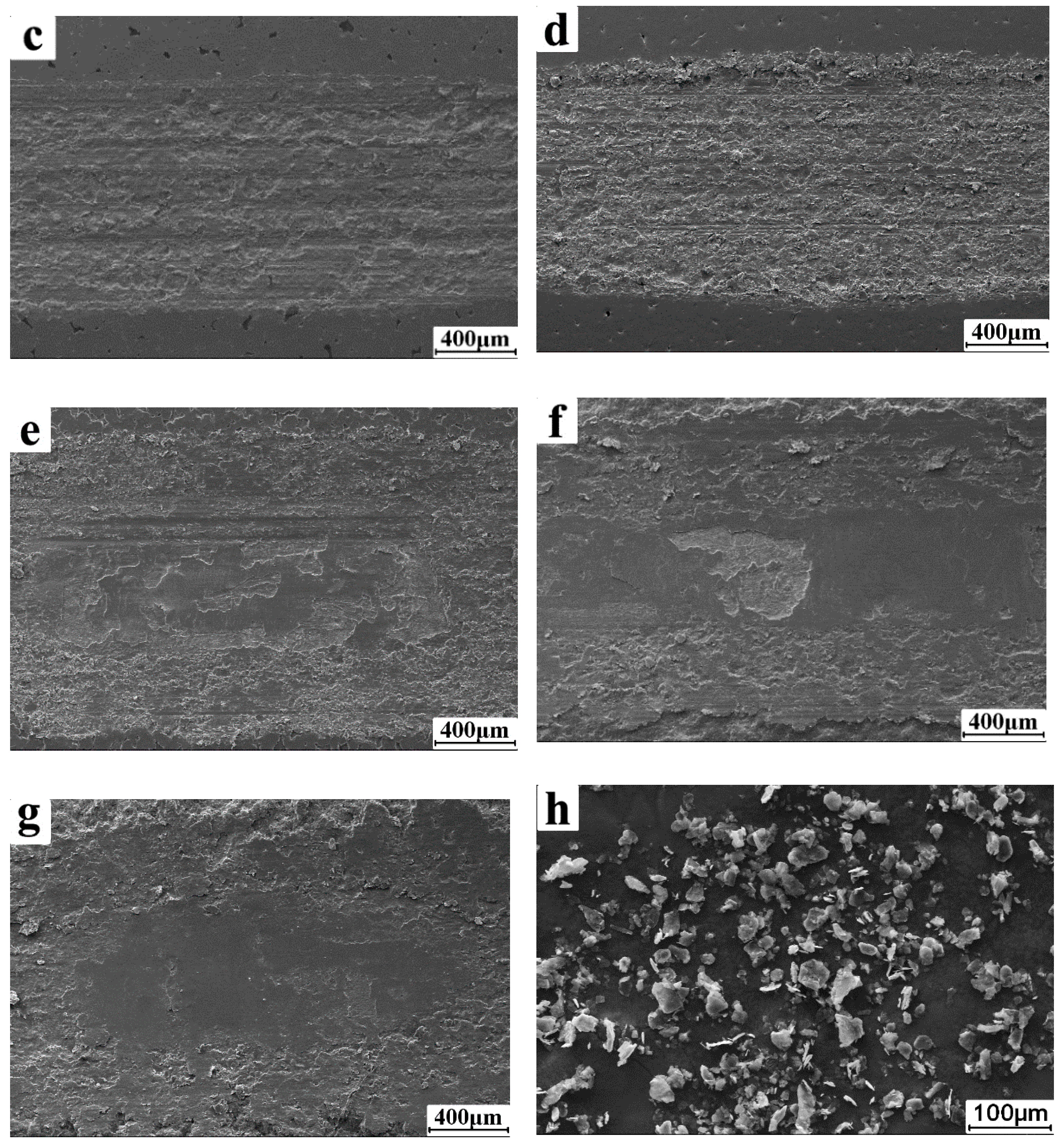
Dry friction and wear results showed that when the graphite content was low (20–40 wt%), the wear form of the coating consisted of abrasive wear. When the graphite content was high (60–100 wt%), the wear form included abrasive wear and delamination wear. Thus, the presence of a conductive polymer coating improved the friction and wear resistance of the matrix.

Author Contributions

Conceptualization, T.L. and X.W.; data curation, Z.L.; formal analysis, Z.L. and S.Z.; writing—original draft, Z.L. and T.L.; writing—review and editing, T.L. and J.Z. All authors have read and agreed to the published version of the manuscript.

Funding

This research was funded by National Natural Science Foundation of China (No. 51804190), Shandong Provincial Natural Science Foundation (No. ZR2021ME240), Youth Science Funds of Shandong Academy of Sciences (No. 2020QN0022), Shandong Province Key Research and Development Plan (Nos. 2019GHZ019, 2019JZZY020329), Jinan Science & Technology Bureau (No. 2019GXRC030), and the Innovation Pilot Project for Fusion of Science, Education and Industry (International Cooperation) from Qilu University of Technology (Shandong Academy of Sciences) (No. 2020KJC-GH03).

Institutional Review Board Statement

Not applicable.

Informed Consent Statement

Not applicable.

Data Availability Statement

Some or all data that support the findings of this study are available from the corresponding author upon reasonable request.

Acknowledgments

This work is supported by Shandong Provincial Key Laboratory of High Strength Lightweight Metallic Materials and Shandong Engineering Research Centre of Lightweight Automobiles Magnesium Alloys, Advanced Materials Institute, Qilu University of Technology (Shandong Academy of Sciences), thanks for their equipment and technical support. We thank LetPub for its linguistic assistance during the preparation of this manuscript.

Conflicts of Interest

The authors declare no conflict of interest.

References

  1. Song, J.F.; She, J.; Chen, D.L.; Pan, F.S. Latest research advances on magnesium and magnesium alloys worldwide. J. Magnes. Alloys 2020, 8, 1–41. [Google Scholar] [CrossRef]
  2. Saberi, A.; Bakhsheshi-Rad, H.R.; Abazari, S.; Ismail, A.F.; Sharif, S.; Ramakrishna, S.; Daroonparvar, M.; Berto, F. A comprehensive review on surface modifications of biodegradable magnesium-based implant alloy: Polymer coatings opportunities and challenges. Coatings 2021, 11, 747. [Google Scholar] [CrossRef]
  3. Yang, Y.; Xiong, X.M.; Chen, J.; Peng, X.D.; Chen, D.L.; Pan, F.S. Research advances in magnesium and magnesium alloys worldwide in 2020. J. Magnes. Alloys 2021, 9, 705–747. [Google Scholar] [CrossRef]
  4. Chen, C.A.; Jian, S.Y.; Lu, C.H.; Lee, C.Y.; Aktuğ, S.L.; Ger, M.D. Evaluation of microstructural effects on corrosion behavior of AZ31B magnesium alloy with a MAO coating and electroless Ni-P plating. J. Mater. Res. Technol. 2020, 9, 13902–13913. [Google Scholar] [CrossRef]
  5. Li, Q.Y.; Zhang, Q.Q.; An, M.Z. Enhanced corrosion and wear resistance of AZ31 magnesium alloy in simulated body fluid via electrodeposition of nanocrystalline zinc. Materialia 2018, 4, 282–286. [Google Scholar]
  6. Rumyantsev, E.; Rumyantseva, V.; Konovalova, V. White phosphate coatings obtained on steel from modified cold phosphating solutions. Coatings 2022, 12, 70. [Google Scholar] [CrossRef]
  7. Li, T.; Leng, Z.J.; Wang, S.F.; Wang, X.T.; Ghomashchi, R.; Yang, Y.S.; Zhou, J.X. Comparison of the effects of pre-activators on morphology and corrosion resistance of phosphate conversion coating on magnesium alloy. J. Magnes. Alloys 2021, in press. [Google Scholar] [CrossRef]
  8. Espinosa, T.; Sanes, J.; Bermúdez, M.D. Halogen-free phosphonate ionic liquids as precursors of abrasion resistant surface layers on AZ31B magnesium alloy. Coatings 2015, 5, 39–53. [Google Scholar] [CrossRef] [Green Version]
  9. Dziková, J.; Fintová, S.; Kajánek, D.; Florková, Z.; Wasserbauer, J.; Doležal, P. Characterization and corrosion properties of fluoride conversion coating prepared on AZ31 magnesium alloy. Coatings 2021, 11, 675. [Google Scholar] [CrossRef]
  10. Zhang, R.F.; Zhang, Z.Y.; Zhu, Y.Y.; Zhao, R.F.; Zhang, S.F.; Shi, X.T.; Li, G.Q.; Chen, Z.Y.; Zhao, Y. Degradation resistance and in vitro cytocompatibility of iron-containing coatings developed on WE43 magnesium alloy by micro-arc oxidation. Coatings 2020, 10, 1138. [Google Scholar] [CrossRef]
  11. Zhu, Y.Y.; Chang, W.H.; Zhang, S.F.; Song, Y.W.; Huang, H.D.; Zhao, R.F.; Li, G.Q.; Zhang, R.F.; Zhang, Y.J. Investigation on corrosion resistance and formation mechanism of a P–F–Zr contained micro-arc oxidation coating on AZ31B magnesium alloy using an orthogonal method. Coatings 2019, 9, 197. [Google Scholar] [CrossRef] [Green Version]
  12. Kania, A.; Szindler, M.M.; Szindler, M. Structure and corrosion behavior of TiO2 thin films deposited by ALD on a biomedical magnesium alloy. Coatings 2021, 11, 70. [Google Scholar] [CrossRef]
  13. Wang, Z.X.; Ye, F.; Chen, L.Y.; Lv, W.G.; Zhang, Z.Y.; Zang, Q.H.; Peng, J.H.; Sun, L.; Lu, S. Preparation and degradation characteristics of MAO/APS composite bio-coating in simulated body fluid. Coatings 2021, 11, 667. [Google Scholar] [CrossRef]
  14. Shang, W.; Wu, F.; Wang, Y.Y.; Rabiei, B.A.; Wen, Y.Q.; Jiang, J.Q. Corrosion Resistance of Micro-Arc Oxidation/Graphene Oxide Composite Coatings on Magnesium Alloys. ACS Omega 2020, 5, 7262–7270. [Google Scholar] [CrossRef] [Green Version]
  15. Chen, Y.N.; Wu, L.; Yao, W.H.; Zhong, Z.Y.; Wu, J.H.; Pan, F.S. One-step in situ synthesis of graphene oxide/MgAl-layered double hydroxide coating on a micro-arc oxidation coating for enhanced corrosion protection of magnesium alloys. Surf. Coat. Technol. 2021, 413, 127083. [Google Scholar] [CrossRef]
  16. Wen, C.L.; Zhan, X.Z.; Huang, X.G.; Xu, F.; Luo, L.J.; Xia, C.S. Characterization and corrosion properties of hydroxyapatite/graphene oxide bio-composite coating on magnesium alloy by one-step micro-arc oxidation method. Surf. Coat. Technol. 2017, 317, 125–133. [Google Scholar] [CrossRef]
  17. Wang, Z.H.; Zhang, J.M.; Bai, L.J.; Zhang, G.J. Microstructure and property of composite coatings on AZ91 Mg-alloy prepared by micro-arc oxidation and electroless Cu-layer. J. Chin. Soc. Corros. Prot. 2018, 38, 391–396. [Google Scholar] [CrossRef]
  18. Buchtík, M.; Kosár, P.; Wasserbauer, J.; Tkacz, J.; Doležal, P. Characterization of electroless Ni–P coating prepared on a wrought ZE10 magnesium alloy. Coatings 2018, 8, 96. [Google Scholar] [CrossRef] [Green Version]
  19. Jian, S.Y.; Lee, J.L.; Lee, H.B.; Sheu, H.-H.; Ou, C.-Y.; Ger, M.-D. Influence of electroless plating on the deterioration of the corrosion resistance of MAO coated AZ31B magnesium alloy. J. Taiwan Inst. Chem. E 2016, 68, 496–505. [Google Scholar] [CrossRef]
  20. Song, Z.; Xie, Z.; Yu, G.; Hu, B.; He, X.; Zhang, X. A novel palladium-free surface activation process for electroless nickel deposition on micro-arc oxidation film of AZ91D Mg alloy. J. Alloys Compd. 2015, 623, 274–281. [Google Scholar] [CrossRef]
  21. Li, C.Y.; Fan, X.L.; Cui, L.Y.; Zeng, R.C. Corrosion resistance and electrical conductivity of a nano ATO-doped MAO/methyltrimethoxysilane composite coating on magnesium alloy AZ31. Corros. Sci. 2020, 168, 108570. [Google Scholar] [CrossRef]
  22. Qing, Y.L.; Wang, G.Z.; Liu, W.X.; Li, B.L.; Sha, W.H. Introduction and research status of conductive. Coat. Mod. Paint. Finish. 2020, 23, 41–44. [Google Scholar]
  23. Li, C.Y.; Yu, C.; Zeng, R.C.; Zhang, B.C.; Cui, L.Y.; Wan, J.; Xia, Y. In vitro corrosion resistance of a Ta2O5 nanofilm on MAO coated magnesium alloy AZ31 by atomic layer deposition. Bioact. Mater. 2020, 5, 34–43. [Google Scholar] [CrossRef] [PubMed]
  24. Peron, M.; Torgersen, J.; Berto, F. Effect of zirconia ALD coating on stress corrosion cracking of AZ31 alloy in simulated body fluid. Procedia Struct. Integr. 2019, 18, 538–548. [Google Scholar] [CrossRef]
  25. Ning, C.M.; Cui, X.J.; Shang, L.L.; Zhang, Y.J.; Zhang, G.A. Structure and properties of different elements doped diamond-like carbon on micro-arc oxidation coated AZ31B Mg alloy. Diam. Relat. Mater. 2020, 106, 9. [Google Scholar] [CrossRef]
  26. Wang, Z.H.; Bai, L.J.; Wang, A.L.; Zhang, G.J. Microstructure and properties of duplex coating on AZ91 magnesium alloy combined with MAO and magnetic sputtering copper. Rare Metal Mater. Eng. 2018, 47, 2561–2566. [Google Scholar]
  27. Chen, M.A.; Cheng, N.; Ou, Y.C.; Li, J.M. Corrosion performance of electroless Ni–P on polymer coating of MAO coated AZ31 magnesium alloy. Surf. Coat. Technol. 2013, 232, 726–733. [Google Scholar] [CrossRef]
  28. Ma, C.A.; Luo, H.X.; Liu, M.Z.; Yang, H.; Liu, H.L.; Zhang, X.Q.; Jiang, L. Preparation of intrinsic flexible conductive PEDOT:PSS@ionogel composite film and its application for touch panel. Chem. Eng. J. 2021, 425, 131542. [Google Scholar] [CrossRef]
  29. Aradhana, R.; Mohanty, S.; Nayak, S. Novel electrically conductive epoxy/reduced graphite oxide/silica hollow microspheres adhesives with enhanced lap shear strength and thermal conductivity. Compos. Sci. Technol. 2018, 169, 86–94. [Google Scholar] [CrossRef]
  30. Li, Y.R.; Chen, K. Research progress on toughening methods of epoxy resin structural adhesive. Shandong Chem. Ind. 2018, 47, 63–64, 66. [Google Scholar]
  31. Chen, J.J.; Huang, H.C.; Fu, Z.E.; Liu, G.H.; Yang, D.; Huang, W.Z.; Miao, M.S. Research progress of carbon based conductive adhesives. China Adhes. 2017, 26, 51–55. [Google Scholar]
  32. Meschi Amoli, B.; Trinidad, J.; Rivers, G.; Sy, S.; Russo, P.; Yu, A.; Zhou, N.Y.; Zhao, B. SDS-stabilized graphene nanosheets for highly electrically conductive adhesives. Carbon 2015, 91, 188–199. [Google Scholar] [CrossRef]
  33. Chandrasekaran, S.; Seidel, C.; Schulte, K. Preparation and characterization of graphite nano-platelet (GNP)/epoxy nano-composite: Mechanical, electrical and thermal properties. Eur. Polym. J. 2013, 49, 3878–3888. [Google Scholar] [CrossRef]
  34. Aradhana, R.; Mohanty, S.; Nayak, S.K. A review on epoxy-based electrically conductive adhesives. Int. J. Adhes. Adhes. 2020, 99, 102596. [Google Scholar] [CrossRef]
  35. Du, W.Q.; Fei, H.; Gu, Q.J.; Wang, L.Y.; He, Q.; Pan, Y.C. Research progress on properties and applications of expansion graphite fixed-based shaped composite phase change material. New Chem. Mater. 2021, 49, 31–35, 40. [Google Scholar]
  36. Akhavan, O.; Ghaderi, E.; Rahighi, R. Toward Single-DNA Electrochemical Biosensing by Graphene Nanowalls. ACS Nano 2012, 6, 2904–2916. [Google Scholar] [CrossRef]
  37. Akhavan, O.; Ghaderi, E.; Rahighi, R.; Abdolahad, M. Spongy graphene electrode in electrochemical detection of leukemia at single-cell levels. Carbon 2014, 79, 654–663. [Google Scholar] [CrossRef]
  38. Kumar, R.; Mohanty, S.; Nayak, S.K. Study on epoxy resin based thermal adhesive composite incorporated with expanded graphite/silver flake hybrids. Mater. Today Commun. 2019, 20, 100561. [Google Scholar] [CrossRef]
  39. Wan, J.J. Preparation and Properties Study of Miceo-Arc Oxidation/Epoxy Resin-Added Copper Composite Conductive Coating on Magnesium Alloy. Master’s Thesis, Xi’an University of Technology, Xi’an, China, 2019. [Google Scholar]
  40. Chen, D.; Chen, G. The conductive property of polyurethane/expanded graphite powder composite foams. J. Reinf. Plast. Compos. 2011, 30, 757–761. [Google Scholar] [CrossRef]
  41. Bhadra, J.; Al Thani, N. Advances in blends preparation based on electrically conducting polymer. Emergent Mater. 2019, 2, 67–77. [Google Scholar] [CrossRef] [Green Version]
  42. Qi, L.; Xie, A.; Chen, T.J.; Han, J.; Yu, L.; Zhang, M. Direct access to xylene solution of polyanilines via emulsion polymerization-extraction method facilitating the preparation of conductive film materials. Mater. Lett. 2019, 254, 361–363. [Google Scholar] [CrossRef]
Figure 1. Surface morphologies of the (a) micro-arc oxidation coating and organic layers with different graphite content: (b) 20 wt%, (c) 40 wt%, (d) 60 wt%, (e) 80 wt%, and (f) 100 wt%.
Coatings 12 00434 g001
Figure 2. Variation in coating roughness with graphite content.
Coatings 12 00434 g002
Figure 3. Cross-section morphologies of the graphite-epoxy coatings: (a) 20 wt%, (b) 40 wt%, (c) 60 wt%, (d) 80 wt%, (e) 100 wt%, and (f) coating interface of the Mg, micro-arc oxidation, and graphite/epoxy (3000×).
Coatings 12 00434 g003
Figure 4. The hardness variation of samples with different surface states.
Coatings 12 00434 g004
Figure 5. Friction coefficients of the coatings: (a) Mg, micro-arc oxidation, and (b) graphite/epoxy resin layer.
Coatings 12 00434 g005
Figure 6. Wear scar morphology of each coating type and graphite powder: (a) Mg, (b) micro-arc oxidation, (c) 20 wt%, (d) 40 wt%, (e) 60 wt%, (f) 80 wt%, (g) 100 wt%, and (h) graphite powder.
Coatings 12 00434 g006aCoatings 12 00434 g006b
Figure 7. Morphology of the wear debris and EDS: (a) Mg, (b) micro-arc oxidation, A is the debris after the wear of MAO coating, which is powdered MgO. B is the massive peeling debris, which is produced by the magnesium matrix under the ceramic coating, (c) 20 wt%, (d) 40 wt%, (e) 60 wt%, (f) 80 wt%, and (g) 100 wt%.
Coatings 12 00434 g007aCoatings 12 00434 g007b
Figure 8. Variations in coating square resistance with changes in graphite content.
Coatings 12 00434 g008
Figure 9. Schematic diagram showing the conductive mechanism of the coating.
Coatings 12 00434 g009
Figure 10. EIS and polarization curves of the Mg, micro-arc oxidation, 80, and 100 wt% samples: (ac) Nyquist, (d) Bode of |Z|, (e) Bode of the phase, and (f) polarization curves.
Coatings 12 00434 g010aCoatings 12 00434 g010b
Table 1. Proportions of each conductive coating portion.
MaterialEpoxy Resin (E-44)Graphite PowderAbsolute EthanolSilane Coupling Agent (KH-550)
Content (wt%)100X515
Table 2. Electrochemical parameters of Mg, micro-arc oxidation, 80 wt%, and 100 wt% samples.
SampleEcorr/VIcorr/A·cm−2Rp/Ω·cm2
Mg−1.4872.933 × 10−487.4
micro-arc oxidation−1.4777.420 × 10−72.66 × 10⁴
80−0.2531.644 × 10−72.65 × 10⁵
100−1.3021.539 × 10−52.82 × 10³
Publisher’s Note: MDPI stays neutral with regard to jurisdictional claims in published maps and institutional affiliations.

