Article

In Vitro Investigation of Corrosion Control of Magnesium with Degradable Polycaprolactone Coatings for Cardiovascular Grafts

1
Department of Cardiothoracic, Transplantation, and Vascular Surgery, Hannover Medical School, 30625 Hannover, Germany
2
Institute for Multiphase Processes, Leibniz University Hannover, 30823 Garbsen, Germany
*
Author to whom correspondence should be addressed.
Coatings 2023, 13(1), 94; https://doi.org/10.3390/coatings13010094
Submission received: 20 December 2022 / Revised: 29 December 2022 / Accepted: 30 December 2022 / Published: 4 January 2023
(This article belongs to the Special Issue Multifunctional Coatings on Medical Devices)

Abstract

:
Magnesium is a promising metal for resorbable cardiovascular implants due to its high biocompatibility, high corrosion tendency, and mechanical properties. However, adapting its corrosion rate to the physiological healing processes is required to ascertain a safe graft function. A protective polymeric layer is supposed to slow down the corrosion rate of magnesium. Additionally, coatings can improve the host’s tissue interaction with the implant by implementing the local delivery of antibiotic drugs and growth or cell adhesion factors. However, little is known about the interaction of polymer-based coatings, their degradation, and magnesium corrosion. This study examines the corrosion mechanism of magnesium protected by spin coatings and electrospun fiber coatings under physiological conditions. Pure magnesium specimens were coated with polycaprolactone (PCL). The corrosion of the coated magnesium was evaluated using an immersion test in simulated body fluid. Spin coatings provided efficient protection against corrosive attacks and a significantly lower corrosion rate by 75% compared to uncoated magnesium. In contrast, fiber coatings did not provide relevant corrosion protection. On the other hand, magnesium corrosion caused the accelerated degradation of the PCL layer. A reliable and safe implant function is vital, especially in cardiovascular applications. Magnesium coating, therefore, should be carried out with spin coatings.

Graphical Abstract

1. Introduction

Magnesium serves as an ideal metallic substrate for different cardiovascular grafts. For instance, a well-known application is temporarily stenting stenosed coronary arteries [1,2,3]. In addition, patients with severe congestive heart failure can also benefit from novel magnesium grafts. Schilling et al. inaugurated the mechanical stabilization of delicate biological patch materials with degradable magnesium scaffolds [4,5,6] for patients with terminal heart failure requiring cardiac transplantation, left ventricular assist device (LVAD) implantation, or surgical reconstruction of the dysfunctional myocardium [7]. The known lack of donor organs and the significantly impaired quality of life after LVAD implantation still limit those therapies today. Thus, reconstructing the dysfunctional myocardium with regenerative biological grafts with the potential for in vivo physiological remodeling is a promising therapeutic approach. Unfortunately, biological grafts, such as small bowel or stomach tissue, display insufficient mechanical stability prior to physiological remodeling. Thus, those grafts have only been used in the low-pressure system of the heart to reconstruct atrial or right ventricular defects [8]. The high blood pressure in the left ventricle would cause life-threatening aneurysms or the rupture of biological grafts. The temporary mechanical stabilization of those grafts with degradable magnesium scaffolds could facilitate their application (see Figure 1). A controlled degradation rate of the magnesium scaffolds is mandatory to ensure a stabilization function that prevents catastrophic failure of the initially delicate biological prosthesis until physiological remodeling leads to increased mechanical stability.
The discrepancy between the corrosion rate of magnesium implants and the physiological remodeling rate of biological grafts limits the widespread combination of these materials. The basic mechanism of Mg corrosion is the reaction of the metallic surface with water (Equation (1)) to form hydrogen, magnesium ions, and hydroxide ions. These ions form an oxide, which stabilizes at high pH values (Equation (2)):
Mg s + 2 H 2 O   Mg 2 + aq + 2 OH aq +   H 2 g
Mg 2 + aq + 2 OH   aq Mg ( OH ) 2 s
In phosphate-containing (simulated) body fluids, Mg(OH)2 transforms into a porous hydroxyapatite (HA)-like oxide layer, which covers the surface and serves as a protective layer for the graft [9]. Coatings are an effective way of controlling these corrosion reactions and adapting the corrosion rate to tissue regeneration.
Most frequently, ceramic coatings, such as hydroxyapatite (HA) [10,11] or silicates [12], have been investigated to improve the corrosion performance of magnesium. A few studies assessed alternative approaches based on polymer coatings [13,14]. In addition to controlling the corrosion reaction, these polymeric coatings offer further possibilities to improve implant performance. Drug delivery systems [14] or improving tissue ingrowth into the implant make polymeric coatings appealing for implant development [15,16].
The electrospinning of fibrous coatings is highly adjustable to those individual requirements [17,18,19,20,21,22]. Two alternatives to create dense polymeric coatings are dip and spin coatings. These methods produce a homogenous, non-porous, and dense layer on the bulk material [14,15], whereas the air-spraying [15] and electrospinning [13] of polymers form a fibrous coating. PCL and polylactic acid (PLA) are researched biomaterials for magnesium coating, which are approved for biomedical use by the FDA (Food and Drug Administration). There is evidence that dense and fibrous/porous polymeric coatings decrease the corrosion rate of magnesium. Xu et al. [16] and Wong et al. [15] showed that PCL coatings on magnesium improve cell attachment and tissue growth around the implant material, which is explained by the decreased magnesium corrosion rates.
Currently, polymer coating is often viewed only from the magnesium’s perspective: how is the corrosion kinetic affected by its coating? The influences of the magnesium corrosion process or products on the coating are rarely considered. Questions such as how long does the coating layer stay intact and how does the degradation change under the harsh conditions of magnesium corrosion (high local pH values and increased metal ion concentration) remain unanswered. The interaction of magnesium corrosion and polymer degradation has only been considered by Chen et al. [14], who reported that magnesium corrosion damaged PLA coatings. They hypothesize that the hydrolysis of the water-permeable PLA coating leads to a decreased pH value, which causes a dissolution of the Mg(OH)2 corrosion layer underneath the coating. This process results in the collapse of the coating and accelerated corrosion of the magnesium [14].
A detailed understanding of the mutual interactions of polymeric coatings, the degradation of the polymer layer, and magnesium corrosion could yield protocols for developing polymer–metallic implants with highly controllable degradation and corrosion rates. Reliable implants would suit various applications in cardiovascular surgery, such as bioresorbable stents or temporarily stabilizing scaffolds for biological grafts.

2. Materials and Methods

In this study, we aim to extend the picture of the influence of magnesium corrosion on polymer degradation. Therefore, we examine the unique characteristics of PCL fiber coating degradation compared to dense, homogenous PCL coatings. The materials were exposed to locally increased pH values caused by magnesium corrosion [14]. The pH value was adjusted to pH 13 assuming that near the magnesium surface the hydroxide ion concentration would be very high. For our experiments, we used high-purity magnesium to eliminate the influence of alloying elements on polymer degradation. Two kinds of experiments were performed. The magnesium corrosion behavior with two different coatings (PCL fiber and PCL spin coating) was studied in a corrosion experiment for 100 h. The behavior of the polymeric fiber material in a harsh environment was studied using immersion tests under high pH values for two weeks. Both experiments were carried out at body temperature (37 °C). This setup took account of the fact that magnesium corrosion proceeds much faster than polymer degradation.

2.1. Sample Preparation for the Mg Corrosion Experiment

For all experiments, cylindrical samples of high-purity magnesium (99.94% pure, Magnesium Elektron UK, Manchester, UK) with a diameter of 8 mm and a height of 2 mm were used. Before coating, the specimens were polished with 1000 grit and cleaned with 70% (w/v) ethanol to reduce the number of particles on the surface. The polymer coating solution and the solution for electrospun fiber mats consisted of 5% (w/v) PCL (molecular weight: 80,000, Sigma-Aldrich Chemistry Corporate, St. Louis, MS, USA) in 2,2,2-trifluoroethanol (TFE, 99.8%, abcr GmbH, Karlsruhe, Germany) in accordance with Degner et al. (2013) [23].

2.2. Polymeric Coating for the Mg Corrosion Experiment

The PCL spin coating was carried out using a spin-coating device (Rotationswerkzeug GRO 12V-35, Bosch, Gerlingen-Schillerhöhe, Germany) that allows a rotational speed of 5000 rpm. This value was evaluated by Xu et al. (2012), who investigated the spinning parameter for a polymeric spin coating on 8 mm cylindrical magnesium plates [16]. The PCL spin-coated specimens (denoted as MgSc) were made by dipping the magnesium specimens into the polymer solution. Subsequently, the rotation leads to spreading the polymer solution onto the specimens’ surfaces. During this process time (30 s), the solvent successively evaporates. The specimens with an electrospun fiber coating (denoted as MgFc) were obtained using an electrospinning device with the same polymeric solution as used for spin coating. The polymeric solution was pumped with 3ml/h through a needle connected to a high voltage (HV) source (15 kV). The Mg specimens were connected to the HV source with a copper wire on the opposite side. The distance between the specimen and the needle tip was 15 cm; the electrospinning took 30 min.

2.3. Characterization of the Coating

The mass of the coating was determined by weighing the sample before and after the coating procedure. A cross-cut test characterized the adhesion of the coatings by cutting a right-angle pattern into the coating and classifying the coating appearance. The thickness of the electrospun and spin coatings was determined via scanning electron microscopy (SEM) (S-3400N, Hitachi High-Tech Analytical Science Ltd., Tubney Woods, Abington, UK) using detached coatings. For this purpose, the coatings could be removed. The detached coatings were frozen in paraffin wax (Tissue-Tek, Sakura Finetek Europe BV, Alphen aan den Rijn, The Netherlands) and cut with a cryotom (Tissue-Tek Cryo3, Sakura Finetek Europe BV, Alphen aan den Rijn, The Netherlands). The thickness was measured via SEM in the cross section. The fiber diameters were measured from SEM pictures using the software ImageJ® before and after the experiment. All fiber measurements were conducted after a drying period of 15 days. To analyze the influence of magnesium corrosion on the coating performance, the coatings were examined using SEM and light microscopy. Raman spectroscopy (Alpha 300 RA, WITec Wissenschaftliche Instrumente und Technologie GmbH, Ulm, Germany) was conducted to observe changes in the molecular structure of the PCL coatings. The wavelength of the Raman laser was 532 nm. The spectra were received using a CCD detector, with an integration time of 1 s and an accumulation of 100.

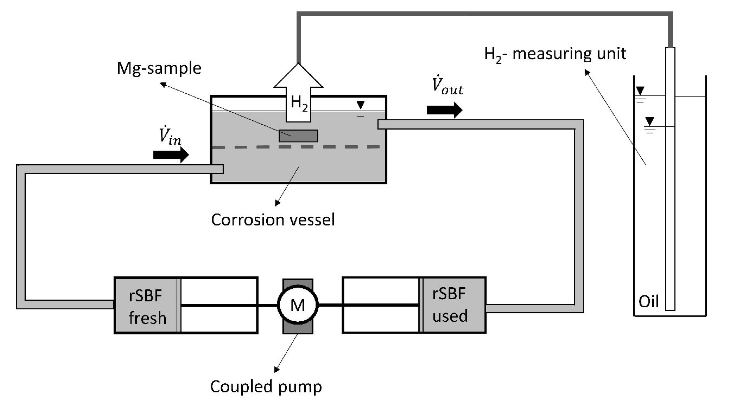
2.4. Magnesium Corrosion Experiment

The magnesium corrosion behavior was measured using an immersion test described by Knigge et al. [24]. The test setup (Figure 2) consists of a corrosion vessel connected to a coupled in- and outflow and a hydrogen measuring unit. The measuring unit consists of a measuring pipe (1ml, BRAND GMBH + CO KG, Wertheim, Germany) connected to the reaction vessel and a glass cylinder (1l, BRAND GMBH + CO KG, Wertheim, Germany) filled with vegetable oil. A continuous flow rate of the testing fluid (1 mL/h) provides constant experimental conditions by exchanging the immersion fluid continuously to avoid the accumulation of hydroxide ions. The syringes hold a volume of 24 mL, so they have to be refilled (inflow) or emptied (outflow) after 24 h. In this step, the pH value of the test fluid was measured in outflow to ensure that the experiment had taken place at a physiological pH value (pH 7.4–7.5).
The magnesium mass loss was calculated from the collected hydrogen using the ideal gas equation (Equation (3)):
n H = R T p V
The pressure p was documented using a barometer (Feingerätebau K. Fischer GmbH, Drebach, Germany). The temperature was controlled using a thermal oven (Memmert GmbH + Co. KG, Schwabach, Germany) at 37 °C. R is the ideal gas constant, V is the measured volume of hydrogen, and nH is the amount of emitted hydrogen in mol. The mass loss of magnesium can be calculated from the amount of hydrogen using Equation (1), which says that 1 mol of magnesium causes 1 mol of hydrogen. The mass loss of magnesium Δm can be calculated using Equation (4):
Δ m M g = n H × 24 , 305   g / m o l
All experiments were conducted at 37 °C and in revised simulated body fluid (rSBF), in accordance with Oyane et al. [25], to simulate a physiological environment (Table 1). The syringes hold a test fluid volume of 24 mL, resulting in the replacement of the syringes after 24 h. A storage-related pH change in the rSBF (in accordance with Oyane et al. (2003) [25]) could thus be prevented.
The following Equation (5) can define the instantaneous corrosion rate (CR):
C R = Δ m A t Δ t
Δm represents the mass loss in mg, A(t) the corroding surface area in mm2 at the time t, and Δt the immersion time in h. Usually, A(t) is equal to the initial surface area. As A(t) is estimated as a constant, the corrosion rates were determined from the Δm/Δt-curve. First, the initial phase in the mass loss curve was identified, characterized by an intense mass loss at the beginning of the immersion. The initial phase was followed by the linear phase, corresponding to a constant corrosion rate. The corrosion rate can be calculated from the interception value of the linear curve, as suggested by Nidadavolu et al. (2016) [26]. Figure 3 shows an exemplary procedure for calculating the corrosion rate.
The immersion time for the coated samples (MgSc and MgFc) was limited to nine days to minimize the influence of the changing surface A(t). The uncoated control (MgUc) was immersed for four days because pure magnesium corrodes very fast.

2.5. PCL Fiber Degradation

It is impossible to measure the magnesium corrosion and fiber degradation in one experiment because the mass loss is connected to both processes. In order to gain a more precise understanding of the degradation mechanism of the PCL fibers in contact with magnesium, an immersion experiment was carried out with fiber mats (denoted as efPCL). The efPCL specimens were cut into squares of 4 cm2, and the mass was measured using a microscale (Cubis, Sartorius AG, Göttingen, Germany). The mats were soaked in 70% (w/v) ethanol for several minutes to clean them and increase their wettability. Afterward, the mats were either immersed into 3 mL modified simulated body fluid (mSBF), or 3 mL NaOH solution with an adjusted pH value of 13, or 3 mL distilled water (control) (Table 1). The surface-to-test-fluid-volume ratio of 2 cm2/mL was adjusted to recommended values according to the DIN 10993-13 guideline [27]. The fiber mats are very sensitive and prone to damage if the test fluid is changed frequently. Therefore, the number of fluid exchanges had to be reduced by choosing a stable SBF. The mSBF was used to determine the influence of electrolytic components on PCL degradation. The hydrogen carbonate content of mSBF is lower than in rSBF (see Table 1). mSBF is suitable for long-term experiments without changing its pH value and without precipitating, according to Oyane et al. [25]. NaOH solution simulates the high pH value in proximity to the corroding magnesium surface. PCL degrades slower than magnesium. The PCL degradation experiment took place at 37 °C. For this reason, a longer immersion time is necessary to detect PCL degradation [28]. After two weeks of immersion, the samples were taken out and dried in a vacuum desiccator (Duran Borosilicate Glass 3.3 Complete Vacuum Desiccator, Fisher Scientific, Leicestershire, UK) for 12 h. The mass loss was measured using a microscale. After the experiment, the immersion fluid pH value was measured using a pH meter (SevenMulti pH Meter, Mettler Toledo, Columbus, OH, USA). Table 2 provides an overview of the experimental setup and surface characterization.

2.6. Characterization of the Fiber Mats

Dynamic differential calorimetry (DSC) was carried out (DSC 204 F1 Phoenix, Netzsch-Gerätebau GmbH, Selb, Germany) to measure the change in crystallinity due to the degradation processes. First, 5–12 mg of the sample material was placed into an aluminum pan with a pierced lid. In accordance with Fricke et al. [29], each sample was scanned twice in a temperature range of 50 °C below the glass transition temperature and 50 °C above the melting temperature. The measurements were taken at a constant heating rate of 10 K/min and a nitrogen flow of 20 mL/min. The efPCL samples were measured from 110 to 110 °C. The temperature curves were evaluated using the software Proteus Analysis by Netzsch. In addition to DSC, Raman spectroscopy was used to visualize changes in the chemical structure of PCL. The Raman spectroscopy was performed in the same way as described in Section 2.2. In addition, SEM images were taken to investigate the fiber morphology before and after the experiment. The fibers were examined after a drying period of 15 days.

2.7. Statistical Analysis

The immersion tests, the corrosion of coated and uncoated magnesium, as well as the degradation of the fibers under different conditions were carried out using four samples in independent experiments. All data, hydrogen volume, and mass loss were statistically analyzed. Error bars show 95% confidence intervals (CI). Normality distribution checks were performed using the D’Agostino and Pearson omnibus tests. The Student’s t-test was used to compute the level of significance. Statistical significance levels are expressed as “ns”—not significant, * p < 0.05, ** p < 0.01, *** p < 0.001, and **** p < 0.0001. The fiber diameter of the electrospun coating and mats and the thickness of the coatings were expressed as means ± standard deviation (SD).

3. Results

3.1. Characterization of the Coating

The coating of MgSc had a thickness of 38 ± 5 µm (n = 16). The mass of the coating was 8 ± 2 mg (n = 4). The cross-cut test for evaluating the adhesion ability shows B1 classification, which refers to a very weak adhesion. The thickness of the fiber coating on the MgFc was approximately 40 µm. The cross-cut test revealed classification B0, referring to no adhesion. The dry electrospun fiber coating mass on each specimen was 16 ± 3 mg for all samples. The mean fiber diameter was 2 µm. The appearance of the uncoated, spin-coated, and electrospun-coated magnesium is depicted in Figure 4. The transparent spin coating covers the magnesium specimen homogenously (Figure 4c). In contrast, the electrospun coating shows curling at the edges of the sample (Figure 4e).

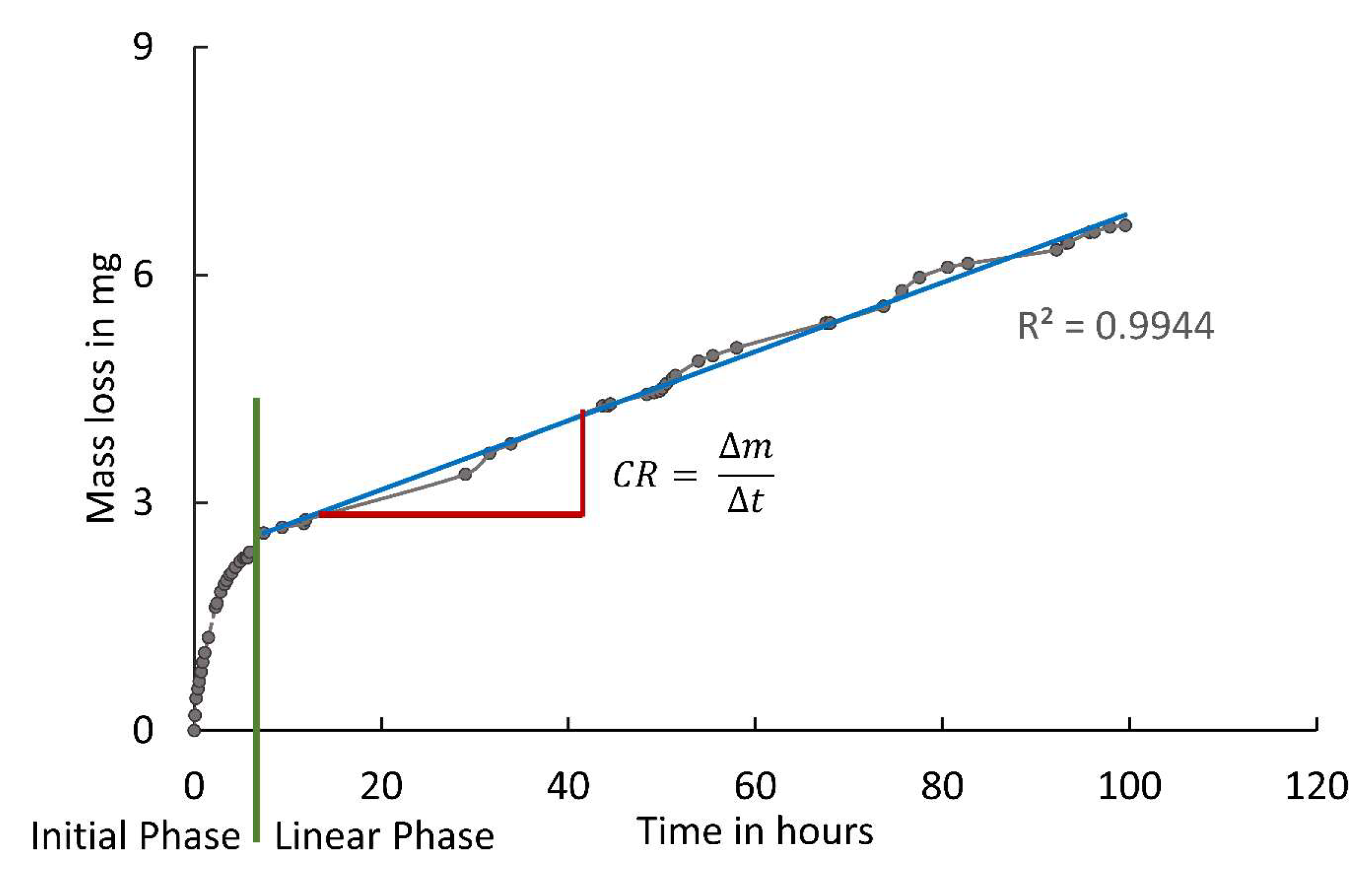
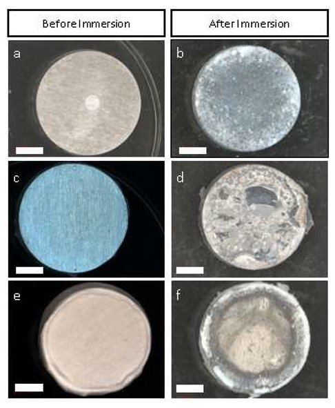
3.2. Magnesium Corrosion Experiment

The corrosion of MgSc and MgFc strongly decreased the initial corrosion rate compared to the uncoated control (Figure 5a,b). The mass loss during the initial phase is reduced by 70% in the MgSc group and 88% in the MgFc group. After the initial phase, all mass loss curves change into a linear curve. No sudden changes in curve characteristics can be observed. The regression (0.9824 ≤ R2 ≥ 0.9944) indicates linearity for the entire observation period of nine days. Figure 5c shows the normalized mass loss rates (Equation (4)) obtained from the linear part of the curves in Figure 5. The mass loss rate of MgSc (0.00095 mg/h cm2 (0.047 mm/y)) is four times lower than the uncoated control (0.0038 mg/h cm2 (0.19 mm/y)) which results from strongly inhibited corrosion in the MgSc group. No corrosion rate can be given for MgFc because a gas bubble formed under the coating during corrosion (Figure 5b). The bubble blocked the fluid contact. Subsequently, extended and nonquantifiable areas of the sample were protected from corrosion. Therefore, no normalized mass loss rate for the fiber coating can be depicted.
There are clear differences between the coated samples and control group, as shown using light microscopy (Figure 4a–d). The uncoated control has an oxide layer covering the entire surface (Figure 4b). In contrast, the MgSc samples show uncorroded surface areas (Figure 4d). In some areas, however, the coating is delaminated and has exposed large parts of the magnesium sample to the rSBF. In these exposed areas, an oxide layer has formed similar to the oxide layer of the uncoated control (Figure 4f). The fiber coating was removed after immersion for a better view of the magnesium surface. The MgFc samples show corroded and uncorroded areas similar to the MgSc samples. The corroded areas are mainly located at the edges of the samples, whereas the central areas remain uncorroded. The PCL fibers on magnesium before the corrosion experiment have a smooth, regular morphology (Figure 6a) with an average fiber diameter of 2.1 ± 0.3 µm (n = 50). After the immersion test of nine days (Figure 6b), the fibers appeared cracked, and some precipitation occurred. The fiber diameter increased up to 2.7 ± 0.5 µm (n = 50). A similar picture of damage emerged with the spin coating on magnesium. Before the immersion test (Figure 4c), the coating presents a dense morphology. After the immersion, the coating became brittle, and some areas showed holes and delamination (Figure 4d).
The SEM in Figure 6a–d shows that the PCL fibers on magnesium before the corrosion experiment have a smooth, regular morphology (Figure 6a) with an average fiber diameter of 2.1 ± 0.3 µm (n = 50). After the immersion test of nine days (Figure 6b), the fibers appeared cracked, and some precipitation occurred. The fiber diameter increased to 2.7 ± 0.5 µm (n = 50). A similar picture of damage emerged with the spin coating on magnesium. Before the immersion test (Figure 6c), the coating presents a dense morphology. After the immersion, the coating became brittle, and some areas showed holes and delamination (Figure 6d).
The Raman spectra show the typical peaks for PCL (Figure 7). The peaks at 1725 cm−1 (νC O) and 1110 cm−1 (νCOC, skeletal stretching) characterize the crystalline phase of PCL. Despite the heavy damage (Figure 6b,d), no change in chemical structure can be detected using Raman spectroscopy. There is no change in the spectra after immersion. The more substantial noise of the spectra of the fiber coatings compared to the spin coating may be due to the fibers’ cylindrical geometry, resulting in focus inaccuracies. The sharp peak at 1725 cm−1 indicates PCL’s predominantly crystalline molecular structure. The presence of a broad peak at 1735 cm−1 would designate the amorphous phase of PCL [30].

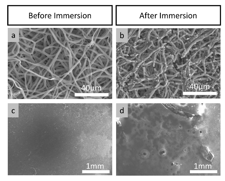
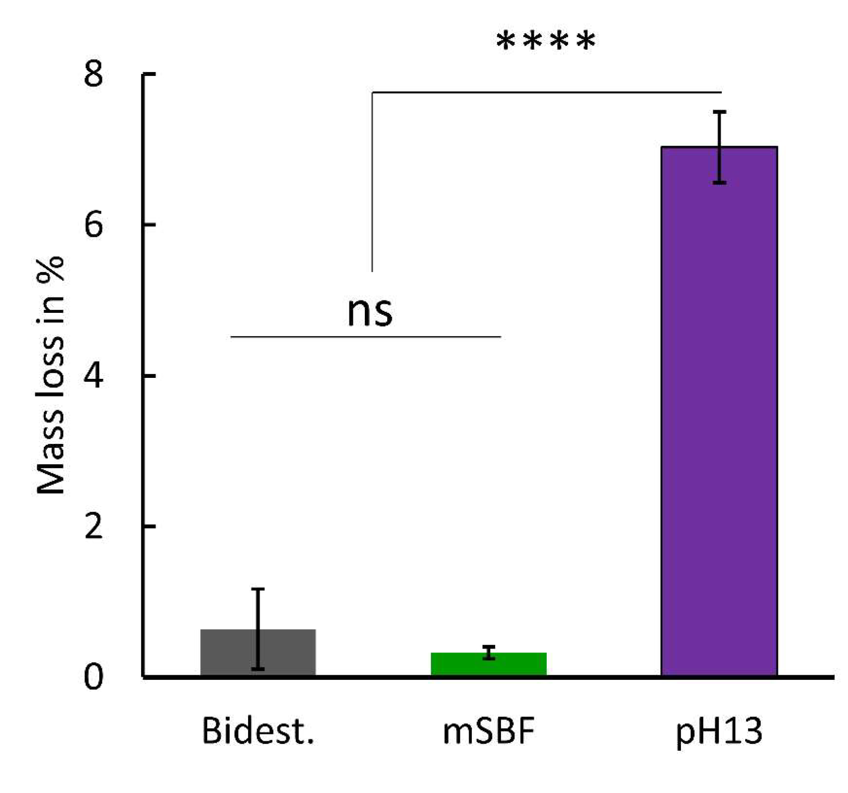
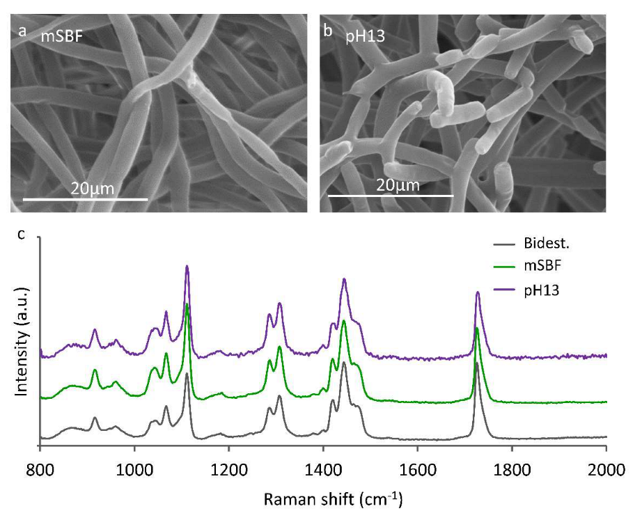
3.3. Fiber Degradation Experiment

The fiber mats show no mass loss in the mSBF solution and dist. water (Figure 8). However, two weeks of immersion in the NaOH solution (pH 13) caused a mass loss of up to 7 wt.%. The pH value of the solutions (see Table 1) were constant during the experimental time.
The fiber morphology is depicted in Figure 9a,b for the fibers degraded in the mSBF and NaOH solutions. The fibers degraded in water show no differences from those degraded in mSBF. Compared to the fiber degradation experiment with a high pH value (Figure 9a), the fibers immersed in mSBF at pH 7.4 show no changes (Figure 9b). The fibers immersed in the NaOH solution (pH 13) suffered similar damages to those observed for the fiber coating (MgFc) (Figure 6b). The Raman spectra of the efPCL degraded in either 0.1M NaOH (pH 13) or mSBF reveal no change in the molecular structure. These findings are consistent with the Raman spectra of MgSc and MgFc (Figure 7).
The increase in the melting enthalpy ΔHm is closely associated with the crystallinity of the polymer [31]. The crystallinity was calculated based on the formula presented in the study of De Cassan et al. [32]. The crystallinity is slightly increased for the efPCL immersed in the NaOH solution (Table 3).

4. Discussion

A controlled corrosion rate of magnesium grafts would open new options for cardiovascular surgery because of magnesium’s excellent biocompatibility and its temporary in vivo function due to its degradation kinetics. The transient stabilization of biological grafts with limited mechanical properties, such as the cholecyst-derived extracellular matrix [33], small bowel [8], stomach [34], bladder [35], or pericardium [36], would facilitate the reconstruction of left ventricular myocardial damage. There is evidence that autologous, vascularized segments of the small bowel or stomach have the potential for the functional replacement of lesioned myocardium after approximately 3 to 6 months of in vivo remodeling [6,8]. This concept of guided tissue engineering would be an ideal therapeutic approach for patients with terminal congestive heart failure that still require the implantation of ventricular assist devices or cardiac transplantation. However, the biological grafts require mechanical support in the phase of their in vivo remodeling, lasting up to 6 months [6], albeit the magnesium alloy support scaffolds are susceptible to a faster corrosion rate even though Schilling et al. employed magnesium fluoride (MgF) coating (chemical conversion) to decelerate the corrosion process [5]. An additional coating could further enhance the stabilizing support of the scaffold’s function until the physiological remodeling of the biological graft provides sufficient mechanical stability, as concluded by Gray et al. [37].
Moreover, polymer coatings not only slow down the corrosion of the metallic structure but also provide better cytocompatibility [38,39]. Applying polymer coatings to metallic substrates includes dip coating, spraying, powder coating, painting, or spin coating [37,38]. Dip coating and fibrous coating are the predominant procedures for biomedical applications. Hence, on the one hand, this study was to determine the influence of dense and fibrous coatings on magnesium corrosion and, on the other hand, the effects of the corrosion process on the polymer layer.

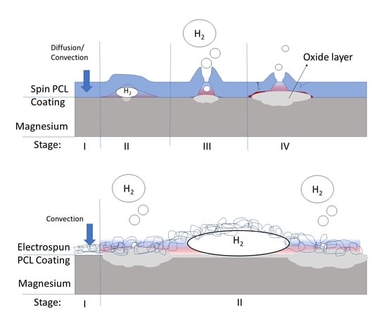
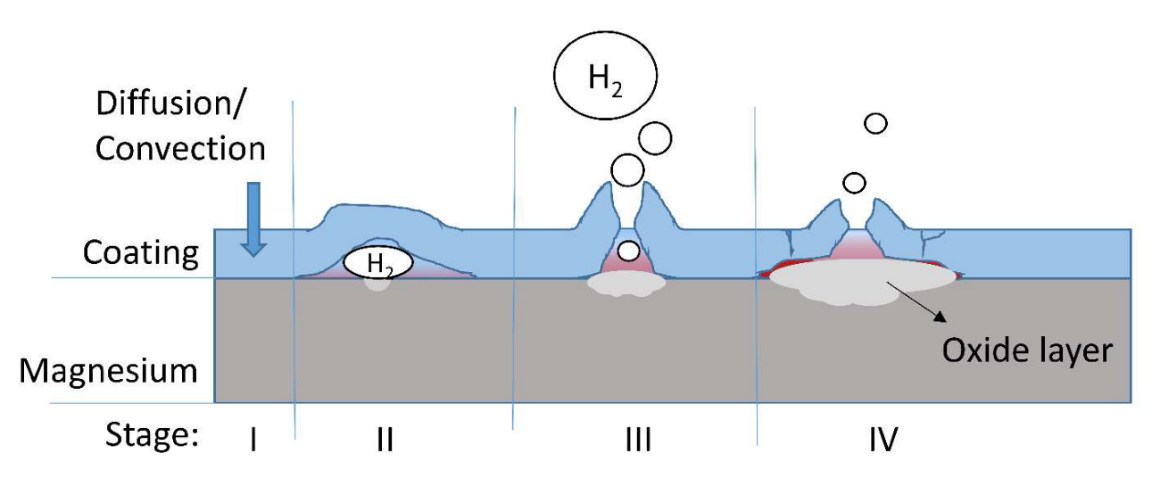
4.1. Corrosion Protection of Magnesium by the Dense Coating

The results of the magnesium immersion test demonstrate that a homogenous, dense coating significantly decelerates magnesium corrosion. Our findings align with the results of Xu et al. who used biodegradable PLLA and PCL films to improve early corrosion resistance and graft cytocompatibility [39]. The authors found that osteosarcoma cells adhered well to the polymer-coated magnesium. They also found a reduced corrosion rate of their magnesium samples, indicated by pH measurement and a reduced volume of released Mg2+ ions. The main underlying mechanism of corrosion protection by coating is a polymer barrier that inhibits the mass transport on the magnesium surface.
Nevertheless, there are two ways to overcome this barrier (Figure 10, Stage I). First, defects in the coating enable convective fluid transport to the magnesium surface, and second, diffusion through the PCL coating [14]. The mass transport through the PCL layer by diffusion is slow and can only cause low corrosion rates underneath the coating. At the same time, defects in the protective coating allow contact of the bare magnesium surface with the corrosive medium, causing corrosion at a higher rate. One product of magnesium corrosion is hydrogen gas (Equation (1)), which enlarges the defect by forming tiny bubbles underneath the coating (Figure 10, Stage II). These bubbles lead to the delamination of the polymer layer. With increasing gas pressure, the probability of a “break open” of the coating rises (Figure 10, Stage III). Subsequently, more fluid can reach the magnesium surface involving larger areas in the corrosion process. The coating prevents the mass transport of degradation products (Mg2+ and OH-), leading to its accumulation underneath the coating. Hence, passivation of the magnesium surface with Mg(OH)2 and calcium phosphates occurs. Eventually, the formed oxide layer provides efficient corrosion protection (Figure 10, Stage IV).
Wong et al. [15] and Abdal-hey et al. [13] reported that the degradation rate of uncoated and coated magnesium after the initial phase converges during the experiment. In contrast, the results in the present study suggest that even a poor coating provides corrosion protection. The control of the pH value significantly impacts the corrosion rate of magnesium. In static conditions, the magnesium corrosion products accumulate in the fluid, and the pH value increases up to a critical pH where a passivating oxide layer is formed [24]. Uncoated and coated magnesium cause different alterations in the pH value of the test fluid because there is a positive correlation between the increase in pH and the corrosion rate. Finally, uncoated and coated magnesium reach a point of passivation if the experimental conditions allow for the accumulation of the degradation products. The inhibition of corrosion by OH accumulation in the control group can lead to an underestimation of the efficiency of the coating. If the experiments of Wong et al. [15] had not taken place in an environment with accumulated degradation products, the effect of the coating in comparison to uncoated magnesium certainly would have been prolonged and clearer.

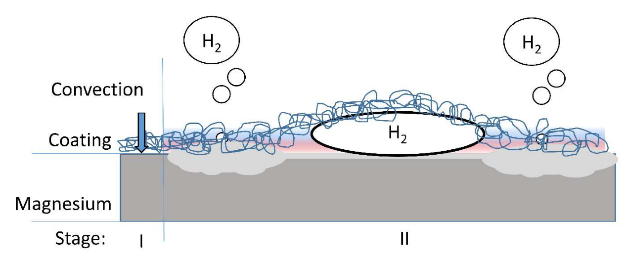
4.2. Corrosion Protection of Magnesium by Fibrous Coating

In contrast to the spin coating (MgSc), the fiber coating (MgFc) does not provide efficient, reproducible corrosion protection. The highly porous mesh of the fibers does not form an efficient barrier against the convection of rSBF to the magnesium surface (Figure 11, Stage I). The specific surface of electrospun fibers, in combination with the hydrophobic properties of PCL (with the contact angle of water on the PCL of 115° [40]), inhibit the gas from permeating the fibrous coating after contact with rSBF. Moreover, the weak adhesion of the coating to the magnesium surface supports spacious delamination. Consequently, a big hydrogen gas bubble in the delamination space between the magnesium surface and the fibrous PCL layer prevents the fluid from reaching the magnesium surface. So, no degradation occurs in these areas (Figure 11, Stage II).
In contrast with these gas-covered areas, the areas with fluid contact show severe degradation. In vivo, e.g., in a blood vessel, big gas bubbles present an unbearable risk of gas embolism for patients.
The magnesium mass loss experiments do not consider the negative difference effect. This results in a little more hydrogen than indicated by the reaction equation (Equation (1)) [41]. Considering leakages and the low but present gas solubility in rSBF, this effect is neglected in this study.

4.3. The Effects of Magnesium Corrosion on the Degradation of PCL Coatings

This study’s second aim was to clarify the influence of magnesium corrosion on PCL coatings. The electrospun fiber degradation experiment demonstrates that the PCL degrades without measurable mass loss in mSBF, which aligns with the results from Taylor et al. [42]. In their study, the degradation experiment shows only a 0.7 wt.% mass loss of PCL in buffered solution after 16 weeks of exposure. The mass loss in high pH values (pH 13) is significant, and the PCL shows accelerated degradation when immersed in a harsh environment. However, the slight damage to the fiber structure, as seen in the PCL fiber experiment compared with the heavy damage in the coating immersion experiment (cracks, precipitation, and increased fiber diameter due to the uptake of water), suggests that the impact of magnesium corrosion on PCL degradation is not fully gauged. The depicted damages of the polymeric coating follow the results of Chen et al. [14] for PLA-coated magnesium, which documented similar damages. The spin coating in their study also suffered from embrittlement and precipitation [14]. The degradation of PCL is detectable by quantifying the increased crystallinity of the material because the amorphous areas in the polymeric structure suffer from degradation first [43]. The Raman spectra should change from a broader peak at around 1736 cm−1 to a sharp peak at 1726 cm−1 with increasing crystallinity [30]. As the crystallinity of the polymer was very high from the beginning, which caused a very sharp peak at 1726 cm−1 before immersion, no change in crystallinity could be detected in the Raman spectra.
DSC offers information regarding the thermodynamic properties. The results of the DSC measurements show increasing crystallinity for electrospun fibers exposed to high pH values that indicates the degradation of the amorphous regions of the PCL material. The increased pH value and metallic cations (Mg2+) may cause a catalytical effect. Stokes et al. [44,45] described the catalytical effect of metal ions in the context of polyurethane degradation. Further research should be undertaken to investigate the influence of metal ions on PCL degradation.
Overall, dense polymer coatings for magnesium-based implants can provide corrosion protection. Despite the possible complicated coating process of complex geometry that may lead to coating defects, the autoinhibiting corrosion process of magnesium can compensate for these defects and inhomogeneities to a certain degree. Electrospun fiber coatings do not provide efficient corrosion protection but should be considered an enhancement for cell interaction or drug delivery. Cardiovascular tissue brings special demands to implants. On the one hand, there are high demands on the mechanical strength, which make the choice of a metallic material appropriate; on the other hand, there is the particularly sensitive tissue, which should be as free as possible from scar tissue [46]. A combination of mechanical strength and the stimulation of healing by functionalized polymers makes polymer-coated magnesium an interesting approach. PCL can be functionalized with cell-binding peptides or cardiac ECM mimicking laminin-1 that support the healing process [47,48] or surfaces treated with laminin that enable stem cell therapy.

5. Conclusions

  • Spin coating can decrease the initial strong corrosion reaction;
  • A dense coating has a prolonged decelerating effect on corrosion because of the diffusion barrier and autoinhibition of the corrosion process;
  • Fiber coatings do not provide efficient protection against corrosive attacks in the conducted experimental conditions;
  • The degradation of the polymer is accelerated in the presence of magnesium corrosion.

Author Contributions

Conceptualization, S.K., M.M., and L.F.; methodology, S.K., M.M. and L.F.; formal analysis, S.K. and L.F.; investigation, S.K. and L.F.; writing—original draft preparation, S.K. and T.S.; writing—review and editing, B.G.; visualization, S.K.; supervision, B.G.; project administration, S.K., M.M. and B.G.; funding acquisition, S.K., T.S., and B.G. All authors have read and agreed to the published version of the manuscript.

Funding

This work was partially supported by the Dr. Jürgen und Irmgard Ulderup Stiftung and Caroline Herschel Program (Equal Opportunities Office) of Leibniz University Hannover.

Institutional Review Board Statement

Not applicable.

Informed Consent Statement

Not applicable.

Data Availability Statement

Not applicable.

Acknowledgments

We are grateful to Hans Jürgen Maier from the Institute of Material Science, Leibniz Universität Hannover, who enabled the sample manufacturing. We also thank Svea Doescher for her excellent technical support.

Conflicts of Interest

The authors declare no conflict of interest.

References

  1. Zhu, J.; Zhang, X.; Niu, J.; Shi, Y.; Zhu, Z.; Dai, D.; Chen, C.; Pei, J.; Yuan, G.; Zhang, R. Biosafety and efficacy evaluation of a biodegradable magnesium-based drug-eluting stent in porcine coronary artery. Sci. Rep. 2021, 11, 7330. [Google Scholar] [CrossRef] [PubMed]
  2. Toušek, P.; Lazarák, T.; Varvařovský, I.; Nováčková, M.; Neuberg, M.; Kočka, V. Comparison of a Bioresorbable, Magnesium-Based Sirolimus-Eluting Stent with a Permanent, Everolimus-Eluting Metallic Stent for Treating Patients with Acute Coronary Syndrome: The PRAGUE-22 Study. Cardiovasc. Drugs Ther. 2022, 36, 1129–1136. [Google Scholar] [CrossRef] [PubMed]
  3. Rukshin, V.; Santos, R.; Gheorghiu, M.; Shah, P.K.; Kar, S.; Padmanabhan, S.; Azarbal, B.; Tsang, V.T.; Makkar, R.; Samuels, B.; et al. A prospective, nonrandomized, open-labeled pilot study investigating the use of magnesium in patients undergoing nonacute percutaneous coronary intervention with stent implantation. J. Cardiovasc. Pharmacol. Ther. 2003, 8, 193–200. [Google Scholar] [CrossRef] [PubMed]
  4. Schilling, T.; Bauer, M.; Biskup, C.; Haverich, A.; Hassel, T. Engineering of biodegradable magnesium alloy scaffolds to stabilize biological myocardial grafts. Biomed. Tech. 2017, 62, 493–504. [Google Scholar] [CrossRef] [PubMed]
  5. Schilling, T.; Brandes, G.; Tudorache, I.; Cebotari, S.; Hilfiker, A.; Meyer, T.; Biskup, C.; Bauer, M.; Waldmann, K.-H.; Bach, F.-W.; et al. In vivo degradation of magnesium alloy LA63 scaffolds for temporary stabilization of biological myocardial grafts in a swine model. Biomed. Tech. 2013, 58, 407–416. [Google Scholar] [CrossRef]
  6. Schilling, T.; Meyer, T.; Brandes, G.; Hartung, D.; Tudorache, I.; Nolte, I.; Wacker, F.; Hilfiker, A.; Hoeffler, K.; Haverich, A.; et al. Left Ventricular Wall Reconstruction with Autologous Vascularized Gastric Graft in a Porcine Pilot Model. Eur. Surg. Res. 2022.
  7. Dor, V.; Saab, M.; Coste, P.; Kornaszewska, M.; Montiglio, F. Left ventricular aneurysm: A new surgical approach. Thorac. Cardiovasc. Surg. 1989, 37, 11–19. [Google Scholar] [CrossRef]
  8. Tudorache, I.; Kostin, S.; Meyer, T.; Teebken, O.; Bara, C.; Hilfiker, A.; Haverich, A.; Cebotari, S. Viable vascularized autologous patch for transmural myocardial reconstruction. Eur. J. Cardiothorac. Surg. 2009, 36, 306–311; discussion 311. [Google Scholar] [CrossRef]
  9. Willumeit, R.; Fischer, J.; Feyerabend, F.; Hort, N.; Bismayer, U.; Heidrich, S.; Mihailova, B. Chemical surface alteration of biodegradable magnesium exposed to corrosion media. Acta Biomater. 2011, 7, 2704–2715. [Google Scholar] [CrossRef]
  10. Song, Y.W.; Shan, D.Y.; Han, E.H. Electrodeposition of hydroxyapatite coating on AZ91D magnesium alloy for biomaterial application. Mater. Lett. 2008, 62, 3276–3279. [Google Scholar] [CrossRef]
  11. Imwinkelried, T.; Beck, S.; Iizuka, T.; Schaller, B. Effect of a plasmaelectrolytic coating on the strength retention of in vivo and in vitro degraded magnesium implants. Acta Biomater. 2013, 9, 8643–8649. [Google Scholar] [CrossRef]
  12. Lin, X.; Tan, L.; Wang, Q.; Zhang, G.; Zhang, B.; Yang, K. In vivo degradation and tissue compatibility of ZK60 magnesium alloy with micro-arc oxidation coating in a transcortical model. Mater. Sci. Eng. C Mater. Biol. Appl. 2013, 33, 3881–3888. [Google Scholar] [CrossRef] [PubMed]
  13. Abdal-hay, A.; Barakat, N.A.; Lim, J.K. Influence of electrospinning and dip-coating techniques on the degradation and cytocompatibility of Mg-based alloy. Colloids Surf. A Physicochem. Eng. Asp. 2013, 420, 37–45. [Google Scholar] [CrossRef]
  14. Chen, Y.; Song, Y.; Zhang, S.; Li, J.; Zhao, C.; Zhang, X. Interaction between a high purity magnesium surface and PCL and PLA coatings during dynamic degradation. Biomed. Mater. 2011, 6, 25005. [Google Scholar] [CrossRef] [PubMed]
  15. Wong, H.M.; Yeung, K.W.K.; Lam, K.O.; Tam, V.; Chu, P.K.; Luk, K.D.K.; Cheung, K.M.C. A biodegradable polymer-based coating to control the performance of magnesium alloy orthopaedic implants. Biomaterials 2010, 31, 2084–2096. [Google Scholar] [CrossRef] [Green Version]
  16. Xu, L.; Yamamoto, A. Characteristics and cytocompatibility of biodegradable polymer film on magnesium by spin coating. Colloids Surf. B Biointerfaces 2012, 93, 67–74. [Google Scholar] [CrossRef]
  17. Repanas, A.; Glasmacher, B. Dipyridamole embedded in Polycaprolactone fibers prepared by coaxial electrospinning as a novel drug delivery system. J. Drug Deliv. Sci. Technol. 2015, 29, 132–142. [Google Scholar] [CrossRef]
  18. Yoshimoto, H.; Shin, Y.M.; Terai, H.; Vacanti, J.P. A biodegradable nanofiber scaffold by electrospinning and its potential for bone tissue engineering. Biomaterials 2003, 24, 2077–2082. [Google Scholar] [CrossRef]
  19. Blakeney, B.A.; Tambralli, A.; Anderson, J.M.; Andukuri, A.; Lim, D.-J.; Dean, D.R.; Jun, H.-W. Cell infiltration and growth in a low density, uncompressed three-dimensional electrospun nanofibrous scaffold. Biomaterials 2011, 32, 1583–1590. [Google Scholar] [CrossRef] [Green Version]
  20. Szentivanyi, A.; Chakradeo, T.; Zernetsch, H.; Glasmacher, B. Electrospun cellular microenvironments: Understanding controlled release and scaffold structure. Adv. Drug Deliv. Rev. 2011, 63, 209–220. [Google Scholar] [CrossRef]
  21. Bode, M.; Mueller, M.; Zernetsch, H.; Glasmacher, B. Electrospun vascular grafts with anti-kinking properties. Curr. Dir. Biomed. Eng. 2015, 1, 459. [Google Scholar] [CrossRef]
  22. Suresh, S.; Gryshkov, O.; Glasmacher, B. Impact of setup orientation on blend electrospinning of poly-ε-caprolactone-gelatin scaffolds for vascular tissue engineering. Int. J. Artif. Organs 2018, 41, 801–810. [Google Scholar] [CrossRef] [PubMed]
  23. Degner, J.; Singer, F.; Cordero, L.; Boccaccini, A.R.; Virtanen, S. Electrochemical investigations of magnesium in DMEM with biodegradable polycaprolactone coating as corrosion barrier. Appl. Surf. Sci. 2013, 282, 264–270. [Google Scholar] [CrossRef]
  24. Knigge, S.R.; Glasmacher, B. Comparison between three in vitro methods to measure magnesium degradation and their suitability for predicting in vivo degradation. Int. J. Artif. Organs 2018, 41, 772–778. [Google Scholar] [CrossRef]
  25. Oyane, A.; Kim, H.-M.; Furuya, T.; Kokubo, T.; Miyazaki, T.; Nakamura, T. Preparation and assessment of revised simulated body fluids. J. Biomed. Mater. Res. A 2003, 65, 188–195. [Google Scholar] [CrossRef]
  26. Nidadavolu, E.P.S.; Feyerabend, F.; Ebel, T.; Willumeit-Römer, R.; Dahms, M. On the Determination of Magnesium Degradation Rates under Physiological Conditions. Materials 2016, 9, 627. [Google Scholar] [CrossRef] [Green Version]
  27. DIN EN ISO 10993-1:2017-04; Biologische Beurteilung von Medizinprodukten—Teil 1: Beurteilung und Prüfungen im Rahmen eines Risikomanagementsystems. Beuth Verlag GmbH: Berlin, Germany, 2017.
  28. Poh, P.S.P.; Hege, C.; Chhaya, M.P.; Balmayor, E.R.; Foehr, P.; Burgkart, R.H.; Schantz, J.-T.; Schiller, S.M.; Schilling, A.F.; Hutmacher, D.W. Evaluation of polycaprolactone—poly-D,L-lactide copolymer as biomaterial for breast tissue engineering. Polym. Int. 2017, 66, 77–84. [Google Scholar] [CrossRef]
  29. Fricke, D.; Becker, A.; Jütte, L.; Bode, M.; de Cassan, D.; Wollweber, M.; Glasmacher, B.; Roth, B. Mueller Matrix Measurement of Electrospun Fiber Scaffolds for Tissue Engineering. Polymers 2019, 11, 2062. [Google Scholar] [CrossRef] [Green Version]
  30. Wesełucha-Birczyńska, A.; Swiętek, M.; Sołtysiak, E.; Galiński, P.; Płachta, Ł.; Piekara, K.; Błażewicz, M. Raman spectroscopy and the material study of nanocomposite membranes from poly(ε-caprolactone) with biocompatibility testing in osteoblast-like cells. Analyst 2015, 140, 2311–2320. [Google Scholar] [CrossRef]
  31. Kong, Y.; Hay, J.N. The measurement of the crystallinity of polymers by DSC. Polymer 2002, 43, 3873–3878. [Google Scholar] [CrossRef]
  32. Cassan, D.; Becker, A.; Glasmacher, B.; Roger, Y.; Hoffmann, A.; Gengenbach, T.R.; Easton, C.D.; Hänsch, R.; Menzel, H. Blending chitosan-g-poly(caprolactone) with poly(caprolactone) by electrospinning to produce functional fiber mats for tissue engineering applications. J. Appl. Polym. Sci. 2020, 137, 48650. [Google Scholar] [CrossRef]
  33. Burugapalli, K.; Pandit, A. Characterization of tissue response and in vivo degradation of cholecyst-derived extracellular matrix. Biomacromolecules 2007, 8, 3439–3451. [Google Scholar] [CrossRef] [PubMed]
  34. Ruel, M.A.; Sellke, F.W.; Bianchi, C.; Khan, T.A.; Faro, R.; Zhang, J.-P.; Cohn, W.E. Endogenous myocardial angiogenesis and revascularization using a gastric submucosal patch. Ann. Thorac. Surg. 2003, 75, 1443–1449. [Google Scholar] [CrossRef] [PubMed]
  35. Badylak, S.F.; Kochupura, P.V.; Cohen, I.S.; Doronin, S.V.; Saltman, A.E.; Gilbert, T.W.; Kelly, D.J.; Ignotz, R.A.; Gaudette, G.R. The use of extracellular matrix as an inductive scaffold for the partial replacement of functional myocardium. Cell Transplant. 2006, 15 (Suppl. 1), S29–S40. [Google Scholar] [CrossRef]
  36. Chang, Y.; Chen, S.-C.; Wei, H.-J.; Wu, T.-J.; Liang, H.-C.; Lai, P.-H.; Yang, H.-H.; Sung, H.-W. Tissue regeneration observed in a porous acellular bovine pericardium used to repair a myocardial defect in the right ventricle of a rat model. J. Thorac. Cardiovasc. Surg. 2005, 130, 705–711. [Google Scholar] [CrossRef]
  37. Gray, J.E.; Luan, B. Protective coatings on magnesium and its alloys—a critical review. J. Alloy. Compd. 2002, 336, 88–113. [Google Scholar] [CrossRef]
  38. Ostrowski, N.; Lee, B.; Enick, N.; Carlson, B.; Kunjukunju, S.; Roy, A.; Kumta, P.N. Corrosion protection and improved cytocompatibility of biodegradable polymeric layer-by-layer coatings on AZ31 magnesium alloys. Acta Biomater. 2013, 9, 8704–8713. [Google Scholar] [CrossRef]
  39. Hornberger, H.; Virtanen, S.; Boccaccini, A.R. Biomedical coatings on magnesium alloys—a review. Acta Biomater. 2012, 8, 2442–2455. [Google Scholar] [CrossRef]
  40. Intranuovo, F.; Gristina, R.; Brun, F.; Mohammadi, S.; Ceccone, G.; Sardella, E.; Rossi, F.; Tromba, G.; Favia, P. Plasma Modification of PCL Porous Scaffolds Fabricated by Solvent-Casting/Particulate-Leaching for Tissue Engineering. Plasma Process. Polym. 2014, 11, 184–195. [Google Scholar] [CrossRef]
  41. Hatami, M.; Yeganeh, M.; Keyvani, A.; Saremi, M.; Naderi, R. Electrochemical behavior of polypyrrole-coated AZ31 alloy modified by fluoride anions. J. Solid State Electrochem. 2017, 21, 777–785. [Google Scholar] [CrossRef]
  42. Taylor, M.S.; Daniels, A.U.; Andriano, K.P.; Heller, J. Six bioabsorbable polymers: In vitro acute toxicity of accumulated degradation products. J. Appl. Biomater. 1994, 5, 151–157. [Google Scholar] [CrossRef] [PubMed]
  43. Kotula, A.P.; Snyder, C.R.; Migler, K.B. Determining conformational order and crystallinity in polycaprolactone via Raman spectroscopy. Polymer 2017, 117, 1–10. [Google Scholar] [CrossRef] [PubMed] [Green Version]
  44. Stokes, K.; McVenes, R.; Anderson, J.M. Polyurethane elastomer biostability. J. Biomater. Appl. 1995, 9, 321–354. [Google Scholar] [CrossRef] [PubMed]
  45. Stokes, K.; Coury, A.; Urbanski, P. Autooxidative Degradation of Implanted Polyether Polyurethane Devices. J. Biomater. Appl. 1986, 1, 411–448. [Google Scholar] [CrossRef] [PubMed]
  46. Jawad, H.; Ali, N.N.; Lyon, A.; Chen, Q.Z.; Harding, S.E.; Boccaccini, A.R. Myocardial tissue engineering: A review. J. Tissue Eng. Regen. Med 2007, 1, 327–342. [Google Scholar] [CrossRef]
  47. Stevens, J.S.; de Luca, A.C.; Downes, S.; Terenghi, G.; Schroeder, S.L.M. Immobilisation of cell-binding peptides on poly-ε-caprolactone (PCL) films: A comparative XPS study of two chemical surface functionalisation methods. Surf. Interface Anal. 2014, 10–11, 673–678. [Google Scholar] [CrossRef]
  48. Boffito, M.; Di Meglio, F.; Mozetic, P.; Giannitelli, S.M.; Carmagnola, I.; Castaldo, C.; Nurzynska, D.; Sacco, A.M.; Miraglia, R.; Montagnani, S.; et al. Surface functionalization of polyurethane scaffolds mimicking the myocardial microenvironment to support cardiac primitive cells. PLoS ONE 2018, 13, e0199896. [Google Scholar] [CrossRef]
Figure 1. Operative situs. Autologous transplantation of a vascularized stomach segment (B) to reconstruct a complete wall defect of the left ventricle (A) in a porcine model. Stabilization of the delicate stomach tissue with a degradable magnesium alloy scaffold (C).
Coatings 13 00094 g001
Figure 2. Experimental setup for measuring magnesium corrosion. The sample was placed in the corrosion vessel perfused with a continuous fluid flow. A coupled pump provided the fluid flow, transporting equal volumes of fluid in and out. The amount of hydrogen is determined using the H2 measuring unit. The level difference between the outer glass cylinder filled with oil and the inner glass pipette filled with the H2 gas was documented.
Coatings 13 00094 g002
Figure 3. An exemplary procedure for calculating the corrosion rate according to Nidadavolu et al. [26]. The linear phase of the curve is identified (start of the linear phase at the green line). The linear part of the curve is approximated with a linear regression (blue). The interception value/corrosion rate can be extracted.
Coatings 13 00094 g003
Figure 4. Light microscopy pictures of the surface of the samples before and after immersion in rSBF: (a) uncoated (MgUc) before immersion; (b) uncoated (MgUc) after immersion; (c) spin-coated magnesium (MgSc) before immersion; (d) spin-coated magnesium (MgSc) after immersion; (e) surface appearance of electrospun fiber-coated magnesium (MgFc) before immersion; (f) and after immersion (removed fiber coating) (white scale bar = 2 mm).
Coatings 13 00094 g004
Figure 5. Corrosion behavior of uncoated (MgUc), spin-coated (MgSc), and electrospun fiber-coated magnesium (MgFc): (a) representative mass loss curves with linear regression (black lines) after the initial phase; (b) bubble formation underneath the fiber coating during corrosion; (c) normalized corrosion rate calculated from the linear regression (n.N.—not named) (** p < 0.01) (n = 4).
Coatings 13 00094 g005
Figure 6. SEM pictures of the coatings before and after immersion in rSBF for nine days: (a) electrospun fiber coating (MgFc) before; (b) and after immersion; (c) spin coating (MgSc) before; (d) and after immersion.
Coatings 13 00094 g006
Figure 7. Raman spectra of the polymeric coatings on magnesium before and after immersion in rSBF for 9 days. Peaks for PCL are the C-COO stretch at 913 cm−1 and 958 cm−1; the C-C stretch at 1034 cm−1, 1064 cm−1, and 1110 cm−1; the CH2-twist at 1284 cm−1 and 1304 cm−1; and the CH2-bend at 1418 cm−1 and 1441 cm−1. Peaks in the spectra that indicate the crystallinity of the PCL are marked by #1 (1110 cm−1) and the C=O stretch at 1725 cm−1 (#2).
Coatings 13 00094 g007
Figure 8. Mass loss of the PCL fibers after immersion in dist. water, mSBF, and NaOH solution (pH 13) for two weeks. (“ns”—not significant, ****p < 0.0001) (n = 4).
Coatings 13 00094 g008
Figure 9. SEM pictures of PCL fiber mats: (a) after immersion in mSBF; (b) and NaOH-solution. (c) Raman spectra of PCL electrospun fiber mats after immersion in dist. water, mSBF, or NaOH-solution (pH 13).
Coatings 13 00094 g009
Figure 10. Schematic representation of the interaction of dense coating with magnesium corrosion. The fluid reaches the magnesium surface (Stage I), a hydrogen bubble forms due to magnesium reacting with the fluid (Stage II), the coating breaks open (Stage III), and accumulation leads to oxide layer formation and passivation (Stage IV).
Coatings 13 00094 g010
Figure 11. Schematic representation of the interaction of fiber coating with magnesium corrosion. The fluid reaches the magnesium surface (Stage I), and a hydrogen bubble forms due to magnesium reacting with water. The bubble is trapped underneath the coating and hinders water from reaching the surface (Stage II).
Coatings 13 00094 g011
Table 1. Composition of the fluids used for the magnesium corrosion and polymer degradation experiments.
IonConcentration in mM
rSBFmSBF0.1 M NaOHH2O Dest.
Na+142.0142.0100-
K+5.05.0--
Mg2+1.51.5--
Ca2+2.52.5--
Cl103.0103.0--
HCO227.010.0--
HPO42−1.01.0--
SO42−0.50.5--
pH7.47.4137
Table 2. Overview of experimental setups and analysis (MgUc: uncoated magnesium, MgSc: spin-coated magnesium, MgFc: electrospun fiber-coated magnesium, efPCL: electrospun fiber mats).
ExperimentMagnesium CorrosionElectrospun Fiber Degradation
SampleMgUcMgScMgFcefPCL
Test fluidrSBFmSBFin 0.1M NaOH (pH 13)H2O dist.
Determination of mass lossH2-measuringMass loss
Coating characterization-Adhesion test-
Coating/fiber morphology-SEMSEM
Surface characterizationOptical-
Molecular structure of fiber/ coating-Raman spectroscopyRaman spectroscopy and DSC
Table 3. Glass transition (Tg), melting temperature (Tm), melting enthalpy (ΔHm), and the calculated crystallinity (xc) of the fiber mats efPCL after two weeks immersion in dist. H2O, mSBF, and NaOH solution (pH 13) (n = 3).
ParameterTg in °CTm in °CΔHm in J/gxc in %
Dist. water −61.260.880.258
mSBF −60.860.279.957.3
NaOH solution −616184.760.8
Disclaimer/Publisher’s Note: The statements, opinions and data contained in all publications are solely those of the individual author(s) and contributor(s) and not of MDPI and/or the editor(s). MDPI and/or the editor(s) disclaim responsibility for any injury to people or property resulting from any ideas, methods, instructions or products referred to in the content.

