Article

Improvement of Wear Performance of Nano-Multilayer PVD Coatings under Dry Hard End Milling Conditions Based on Their Architectural Development

1
Department of Mechanical Engineering, McMaster University, 1280 Main St. West, Hamilton, ON L8S4L7, Canada
2
Micro Materials Limited, Willow House, Yale Business Village, Ellice Way, Wrexham LL13 7YL, UK
3
Materials Research Laboratory, Kobe Steel Ltd., 1-5-5 Takatsuda-dai, Nishi-ku, Kobe, Hyogo 651-2271, Japan
4
LMA-Laboratory of Advanced Microscopy, INA—Institute of Nanoscience of Aragón, University of Zaragoza, E-50018 Zaragoza, Spain
5
Department of Physics Condensed Matter, University of Zaragoza, E-50009 Zaragoza, Spain
*
Author to whom correspondence should be addressed.
Coatings 2018, 8(2), 59; https://doi.org/10.3390/coatings8020059
Submission received: 14 December 2017 / Revised: 19 January 2018 / Accepted: 1 February 2018 / Published: 5 February 2018
(This article belongs to the Special Issue Coatings for Cutting Tools)

Abstract

:
The TiAlCrSiYN-based family of PVD (physical vapor deposition) hard coatings was specially designed for extreme conditions involving the dry ultra-performance machining of hardened tool steels. However, there is a strong potential for further advances in the wear performance of the coatings through improvements in their architecture. A few different coating architectures (monolayer, multilayer, bi-multilayer, bi-multilayer with increased number of alternating nano-layers) were studied in relation to cutting-tool life. Comprehensive characterization of the structure and properties of the coatings has been performed using XRD, SEM, TEM, micro-mechanical studies and tool-life evaluation. The wear performance was then related to the ability of the coating layer to exhibit minimal surface damage under operation, which is directly associated with the various micro-mechanical characteristics (such as hardness, elastic modulus and related characteristics; nano-impact; scratch test-based characteristics). The results presented exhibited that a substantial increase in tool life as well as improvement of the mechanical properties could be achieved through the architectural development of the coatings.

1. Introduction

It is well known that high hardness, low thermal conductivity and high adhesion to the substrate are the key properties of wear resistant coatings helping them to sustain the heavy loads/high-temperature operating conditions during cutting [1]. This is especially true for severe/extreme frictional conditions associated with dry high-performance machining of hardened steels [2]. High hardness combined with the low thermal conductivity is mandatory for continuous dry cutting conditions associated with hard turning [1]. However, when the cutting environment becomes more complex, as in interrupted cutting conditions the coating layer must achieve improved multi-functionality [3]. Modern hard PVD (Physical vapor deposition) coatings mostly have a nano-crystalline columnar structure [4]. The introduction of more complex coatings which combine nano-columnar and nano-laminated structures [5] critically improves the multi-functionality of the coating layer [6]. To improve further even more complex architectures must be considered, such as incorporation of interlayer along with multilayer coatings (i.e., bi-multilayer coatings) with a potential to improve micro-mechanical characteristics, such as adhesion to substrate [7] and impact fatigue fracture resistance. In general nano-laminates are effective in reducing the brittleness of hard coatings [8]. The brittleness of the hard coating is a very important factor to be addressed under interrupted cutting conditions where poor low cycle fatigue performance is a parameter that limits tool life [2,3]. This characteristic of the coating could be evaluated through the nano-impact fracture resistance [9]. A unique feature of the nano-laminates is that they can provide: simultaneous frictional energy accumulation due to the ability to prevent intensive plastic deformation and dissipation through providing crack deflection under operation [10,11]. It has been shown elsewhere that an increased number of nano-layers could improve the impact fatigue fracture resistance due to the higher number of nano-layer interfaces which serve as sites for crack deflection [12]. This toughening strategy includes the development of multilayered structures with a high number of interfaces for crack deflection [12]. Additionally, it is very important to achieve a balance between high compressive stress that prevents excessive chipping under operation but could also lead to poor adhesion to the substrate and low residual stress (no crack retardation) [13].
It was also stated in [14] that greater load support (resistance to plastic deformation) that scales with H3/E2 ratio [14] can show excellent correlation with the impact fatigue fracture resistance. It minimizes the probability of cracks initiating in the first place (hindering of dislocation movement by the layer interfaces in the nano-multilayer coatings under loading). A larger H3/E2 ratio means that a surface layer with better load support remains closer to elastic for longer. Eventually it results in spatial localization of damage. Deformation localization is essential to avoid degradation of the structural and mechanical integrity of the entire surface engineered structure [15]. In general, increased energy dissipation density and damage localization are key challenges for engineered materials, especially those with high brittleness that are prone to radial cracking and catastrophic fracture as a leading failure mechanism. This failure is typical for interrupted cutting conditions.
We also must note that under interrupted cutting conditions exposure to the environment is enhanced within the cutting zone in comparison to continuous cutting. Under such conditions the thermal protection of the cutting tool could be efficiently achieved not only by the coating layer by itself, but also because of the formation of thermal-barrier tribo-ceramic films on the surface through self-organization during friction [16]. The nano-laminated coating with higher number of layers contains bigger amount of lattice defects [16]. Therefore, it possesses a higher non-equilibrium state and has enhanced catalytic features [17]. In this way formation of thermal barrier tribo-films on the friction surface could be accelerated and the wear rate is reduced. Consequently, such coatings can exhibit a wider range of multi-functional properties.
The general idea of the surface engineered layer optimization is to create an architecture that provides adaptive spatio-temporal behavior of the coating [17]. In this way the next generation of coatings could be developed. Such a coating would be able to provide the following: the highest possible adhesion to the substrate; the ability of the coating layer to accumulate and dissipate energy simultaneously, which is typical for nano-laminated structures; high surface protection/lubrication with an additional objective of better wear behavior in a highly loaded contact. Therefore, the goal of this paper is to present the results of investigation on the improvement in the architecture of the TiAlCrSiYN-based PVD coatings in relation to the various mechanical and tribological characteristics that show promise for hard high-speed end milling applications.

2. Materials and Methods

Different architectures of TiAlCrSiYN-based coatings were investigated: (a) monolayer; (b) multilayer; (c) bi-multilayer with varying thickness of the multilayer.
Ti0.2Al0.55Cr0.2Si0.03Y0.02, Ti0.15Al0.6Cr0.2Si0.03Y0.02 targets, which were fabricated by a powdered metallurgical process, were used for monolayer Ti0.2Al0.55Cr0.2Si0.03Y0.02N and nano-multilayered Ti0.2Al0.55Cr0.2Si0.03Y0.02N/Ti0.25Al0.65Cr0.1N coatings deposition.
Mirror polished cemented carbide WC-Co substrates (SPG 422, SPGN12 03 08) were selected for coating characterization and Mitsubishi C-2SB ball nose end mills were chosen for cutting-tool life studies. Coatings were deposited in an R&D-type hybrid PVD coater (Kobe Steel Ltd., Kobe, Japan) using a plasma-enhanced arc source. Samples were heated up to about 500 °C and cleaned through an Ar ion etching process. An Ar-N2 mixture of gas was fed into the chamber at a pressure of 2.7 Pa with a N2 partial pressure of 1.3 Pa. The arc source was operated at 100 A for a 100 mm diameter × 16 mm thick target. Other deposition parameters were: bias voltage 100 V; substrate rotation 5 rpm. The thickness of the coatings studied was adjusted depending on the thickness required through the time of deposition for the film characterization and cutting test work.
Full scale comprehensive characterization of the ball nose end mills tool life was performed. Cutting conditions are shown in Table 1.
The crystal structure and preferred orientation of the coating were determined with X-ray diffraction (XRD, Rigaku ULTIMA-PC, Rigaku, Tokyo, Japan) using Cu Kα radiation. The residual stress evaluation was by means of a conventional X-ray diffractometer, using the multiple hkl method [18]. In this method, Cu Kα radiation beam with glancing incidence angle of 1.0° was used combined with a parallel beam geometry. Equation (1) indicates a stress—strain relationship of a solid material.
ε ϕ ψ = 1 2 S 2 sin 2 ψ [ σ 11 cos 2 ϕ + σ 12 sin ( 2 ϕ ) + σ 22 sin 2 ϕ ] + 1 2 S 2 [ σ 13 cos ϕ sin ( 2 ψ ) + σ 23 sin ϕ sin ( 2 ψ ) + σ 33 cos 2 ψ ] + S 1 [ σ 11 + σ 22 + σ 33 ]
ε is the strain of a crystallographic plane whose direction, i.e., the direction of the diffraction vector is usually described by angles ψ (angle of inclination of the specimen surface normal about the diffraction vector) and ϕ (the anticlockwise rotation of the specimen around the specimen surface normal). σij (i, j = 1, 2, 3) represents a stress tensor and S1 and ⅟₂S2 are X-ray elastic constants as defined by Equation (2).
S 1 = ν E 1 2 S 2 = 1 + ν E
In the multiple hkl method, stress σij can be calculated by measuring changes in lattice spacing d of multiple planes and resulting strain ε ϕ ψ h k l , defined as ε ϕ ψ h k l = d i d i 0 d i 0 (di represents measured lattice spacing and di0 is strain-free lattice spacing of di. Assuming that the tensor component satisfies, σ33 = 0, σ23 = σ13 =0, σ11 = σ22 = σ, then Equation (1) becomes Equation (3).
ε ϕ ψ h k l = σ [ 1 2 S 2 h k l sin 2 ψ + 2 S 1 h k l ]
Stress can be calculated by the slope of ε ϕ ψ h k l to sin 2 ψ relationship. In this study, all coating material exhibits a cubic crystal structure but the elastic constant is assumed to be hkl dependent. Young modulus was obtained from [19]. Young modulus of (111) direction was assumed to be 400 GPa and for other directions it was calculated. The value di0 was calculated by the law of mixture, using a lattice constant of cubic AlN (JCPDS 25-1495, a = 0.414 nm), CrN (JCPDS 11-65, a = 0.14 nm), TiN (JCPDS 38-1420, a = 0.424173 nm), hypothetical cubic SiN and YN using ionic radius of Si and Y, being a = 0.3271 nm and a = 0.4409 nm respectively. The micro-mechanical characteristics of the coatings were measured on the WC-Co. substrate using a Micro Materials NanoTest system (Nano-test vantage, Micro Materials Ltd., Wrexham, UK). Nanoindentation was performed in a load-controlled mode with a Berkovich diamond indenter calibrated for load, displacement, frame compliance and indenter shape. The area function for the indenter was determined by indentation into a fused silica reference sample. For the nanoindentation of the coatings, the peak load was 40 mN and 40 indentations were performed for each coating. This load was chosen to minimize any influence of surface roughness on the data while ensuring that the indentation contact depth was less than 1/10 of the film thickness so that a coating-only (load-invariant) hardness could be measured in combination with coating-dominated elastic modulus. Nano-impact testing was performed with a NanoTest fitted with a cube corner indenter as an impact probe. The indenter was accelerated from 12 µm above the coating surface with 20–30 mN coil force to produce an impact every 4 s for a total test duration of 30–300 s. The coatings’ nano-impact fatigue fracture resistance was assessed by the final measured impact depth and confirmed by microscopic analysis of impact craters. Micro-scratch tests were performed to a peak load of 5 N using the NanoTest Scratching Module with a 25 μm radius diamond probe.
Cutting-tool life was studied under the conditions mentioned in Table 1. At least three cutting tests were performed for each kind of coating under the corresponding operations. The scatter of the tool-life measurements was approximately 10%. Cutting tests have been performed during dry ball-nose end milling (Mitsubishi carbide end mills, D = 10 mm) of the hardened AISI H13 tool steel with hardness HRC 53–55 under extreme cutting conditions. The coated tool flank wear was measured using an optical microscope (Mitutoyo modelTM, Mitutoyo Corporation, Kawasaki, Japan). A tool dynamometer (9255B, Kistler, Winterthur, Switzerland) was used to measure the cutting forces.

3. Results and Discussion

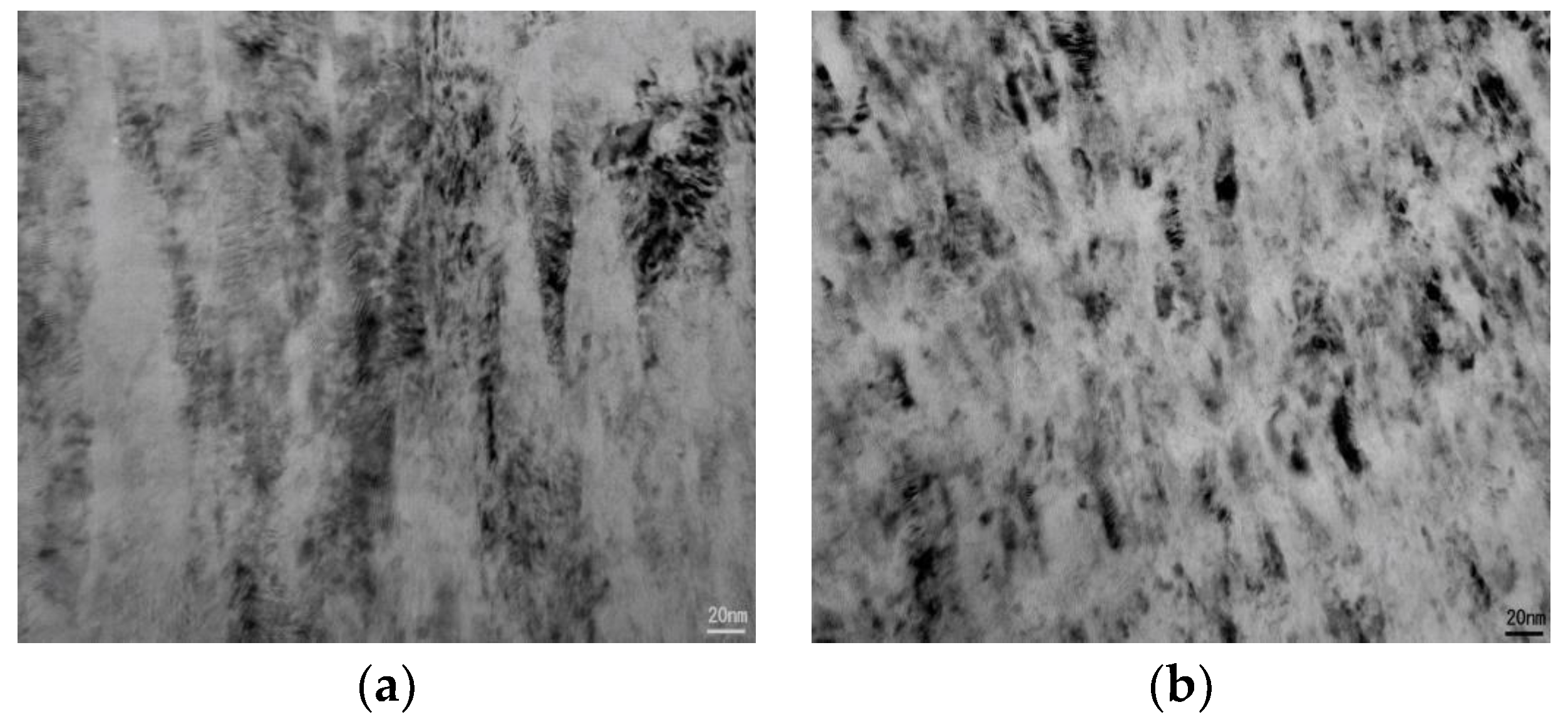
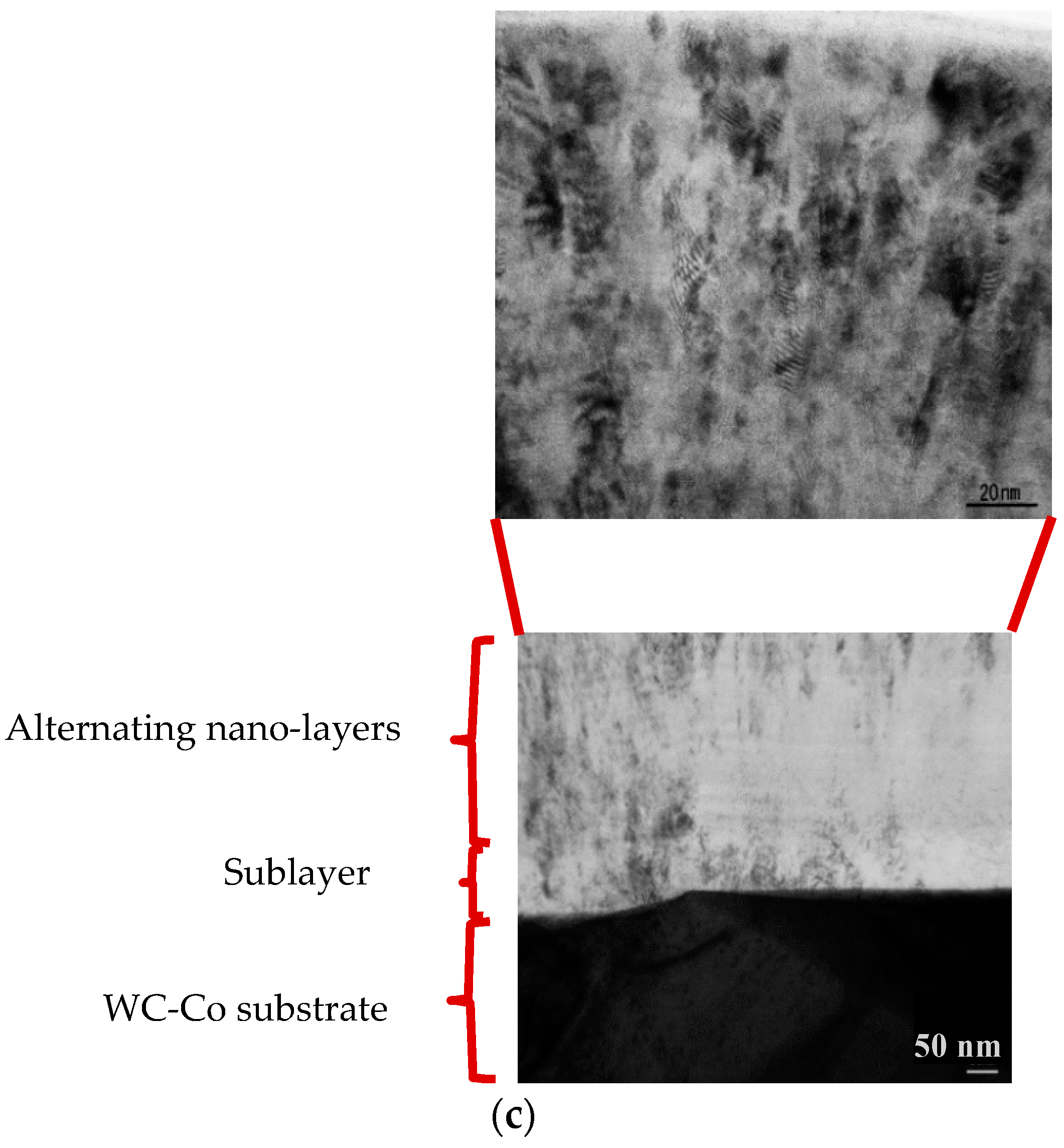
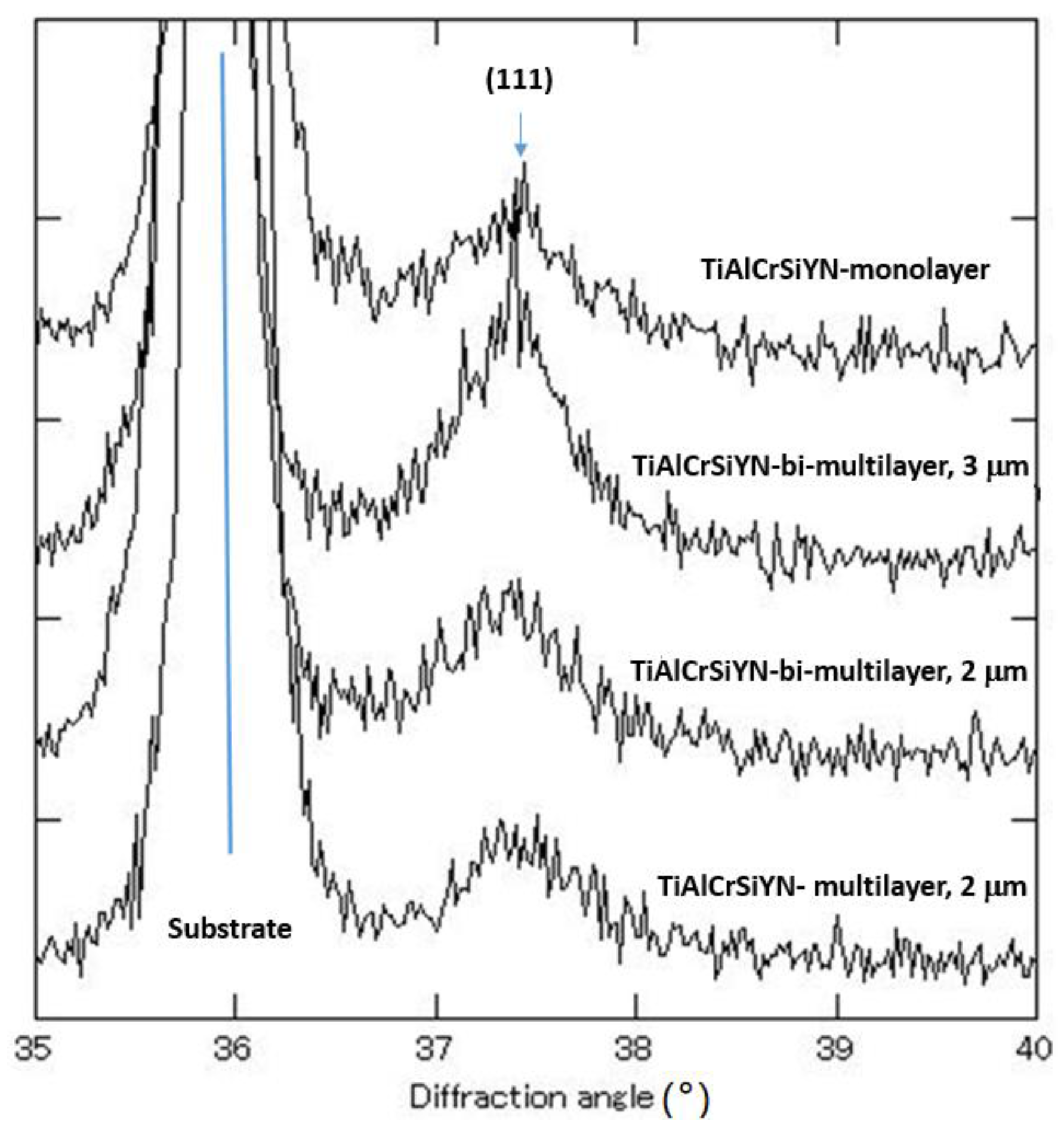
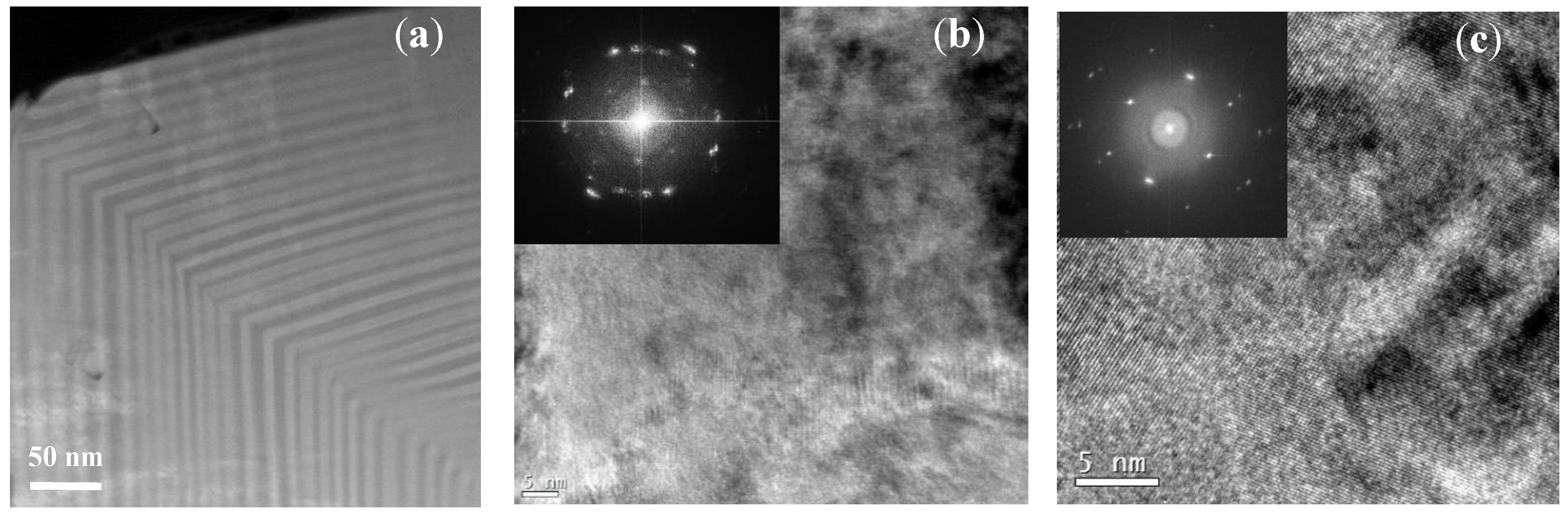
3.1. Structural Analysis

Comparative structural analysis of the monolayer, multilayer and bi-multilayer coatings is shown in Figure 1. The data show that monolayer coating has a nano-crystalline columnar structure (Figure 1a); nano-multilayered coating also has columnar structure with alternating nano-layers (Figure 1b). It was shown previously that these nano-layers are TiAlCrSiYN [20] and TiAlCrN [21]. The bi-multilayer coating has a TiAlCrN sublayer, approximately 100 nm thick (Figure 1c). Alternating nano-layers are identical in both multilayer and bi-multilayer coatings (Figure 1b,c). X-ray diffractorgams of all the coatings studied are presented in Figure 2.

3.2. Mechanical Properties

3.2.1. Residual Stress

Table 2 shows that the residual stress is highly compressive for all the coatings studied. This range of residual stress is normal for the multilayer PVD coatings deposited under conditions specified in the experimental section [22]. This is beneficial considering the heavy loaded conditions associated with the experiments performed and prevents excessive chipping of the cutting edge under operation. The monolayer TiAlCrN coating has a nano-crystalline structure [20] and the lowest range of compressive residual stress (Table 2). The monolayer TiAlCrSiYN coating has a slightly higher level of compressive residual stress (Table 2). This is due to the grain size refinement and formation of ultra-fine nano-crystalline structure in this coating as compared to the TiAlCrN one [23]. Grain size refinement is associated with the higher number of defects on the nano-grain boundaries [24] that results in residual stress growth. The multilayer, 2 microns thick coating has even a higher range of residual stress. This is again associated with the further growth of defects at the alternating nano-layer interfaces [16]. However, the bi-multilayer structure resulted in a reduction in the residual stress due to the introduction of a TiAlCrN sublayer having a lower residual stress (Table 2). An increase in the thickness of the bi-multilayer coating from 2 to 3 microns leads to the further reduction of residual stress (Table 2). With other parameters being the same, the thickness increase could lead to a reduction of compressive residual stress as has been shown in [25]. This consideration can limit the overall thickness of bi-multilayer coating to prevent further reduction in the compressive stress, or conversion to tensile that could lead to flaking of the coating off the cutting tool.

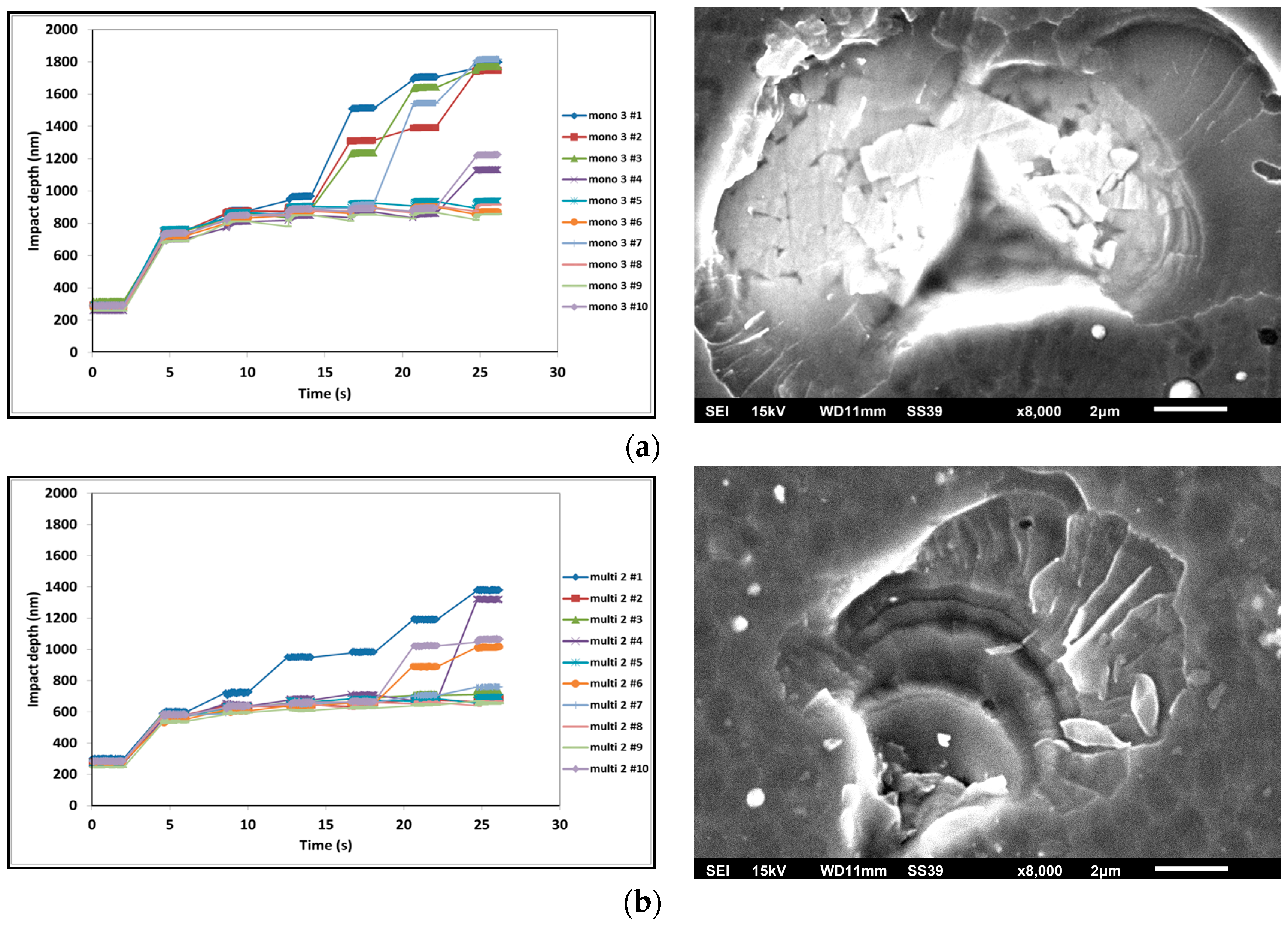
3.2.2. Micro-Mechanical Properties

Micro-mechanical properties of the coatings are summarized in Table 3. The hardness of all the coatings is similar. However, the bi-multilayer coatings are slightly harder and have a lower plasticity index. The most pronounced difference is in the H3/E2 ratio, which is related to load support (Table 3). It has the highest value for the bi-multilayer coating with a thickness of 2 microns. The short-term impact test data are summarized in Table 4. Corresponding impact fatigue fracture resistance data is shown in Figure 3. SEM (TESCAN VP Scanning Electron Microscope, NanoImages, LLC, Pleasanton, CA, USA) images of the impact craters correlate to the numerical data presented (Table 4; Figure 3): monolayer coating has an abrupt fracture with WC-Co. substrate exposure; 2 micron thick bi-multilayer coating shows crack deviation along the nano-layer interfaces; 3 micron thick bi-multilayer coating show the best fatigue performance with minimal surface damage. The data indicates that impact behavior is a combination of the load support and micro-structural advantages. Although both the 2 and 3 µm bi-multilayers have low plasticity they have a structural advantage (multi-layering vs. monolayers) that means cracking could be non-propagating thus, do not result in more dramatic fracture. This characteristic is in good correlation with the wear behavior during the running-in stage. The initial (during running-in stage) higher flank and rake wear as well as cutting forces (see below) are consistent with some observed fracture but it is more localized. In comparison any fracture on the monolayers results in more dramatic wear in the impact tests and in the cutting tests.
Longer-term impact fatigue fracture resistance data, presented in Figure 4, confirm the trend outlined above in Figure 3. These two characteristics relate to the chipping intensity of the coated tool (see tool-life data presented below). Table 3 shows that the bi-multilayers have higher H3/E2 ratios, which can aid crack resistance, as seen in the nano-impact data (Figure 4). The 2 µm thick coating has a higher H3/E2 ratio but being thinner it provides less load support to the substrate than the 3 µm bi-multilayer one. In the nano-impact test the interlayer function is critical to effectively stop the total coating failure and substrate exposure. The combination of the multilayer structure and the interlayer hinders crack propagation to reach the substrate. As shown in Figure 4, the 2 µm thick coating flakes off from the interface (between coating and substrate) after around 60 s, whereas the 3 µm bi-multilayer coating shows gradual impact depth increase vs. time. This means that the thicker coating provides better surface protection than the thinner one. One explanation might be that most of the impact energy is absorbed inside the coating layers and thus does not reach the interface, thereby preventing substrate deformation.
Micro-scratch data show that bi-multilayer coatings possess significantly better scratch crack propagation resistance (CPRs parameter) as compared to the multilayer one (Table 3). Most probably this is due to the presence of the slightly softer TiAlCrN interlayer, which improved the adhesion of the bi-multilayer coating to the carbide substrate.

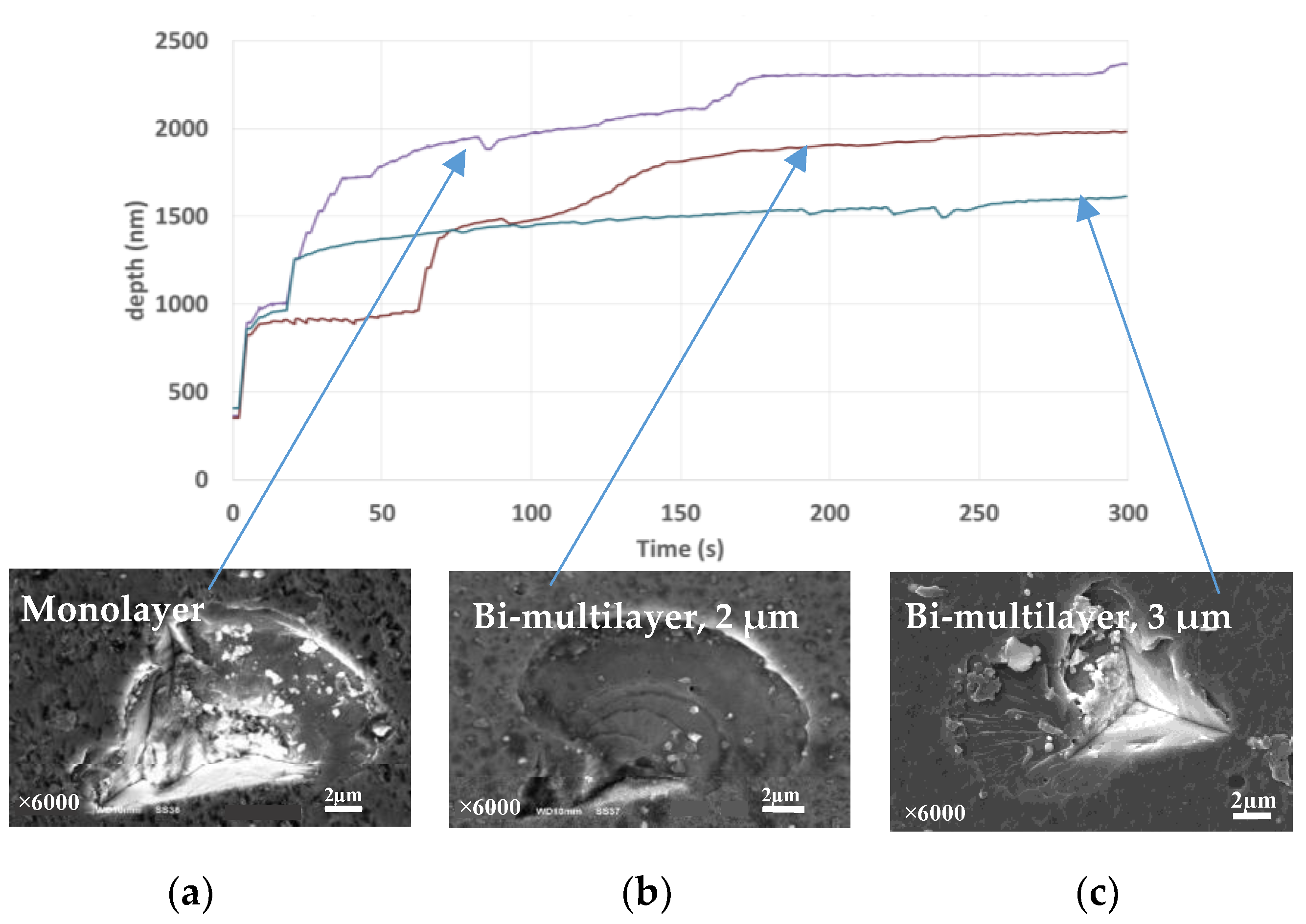
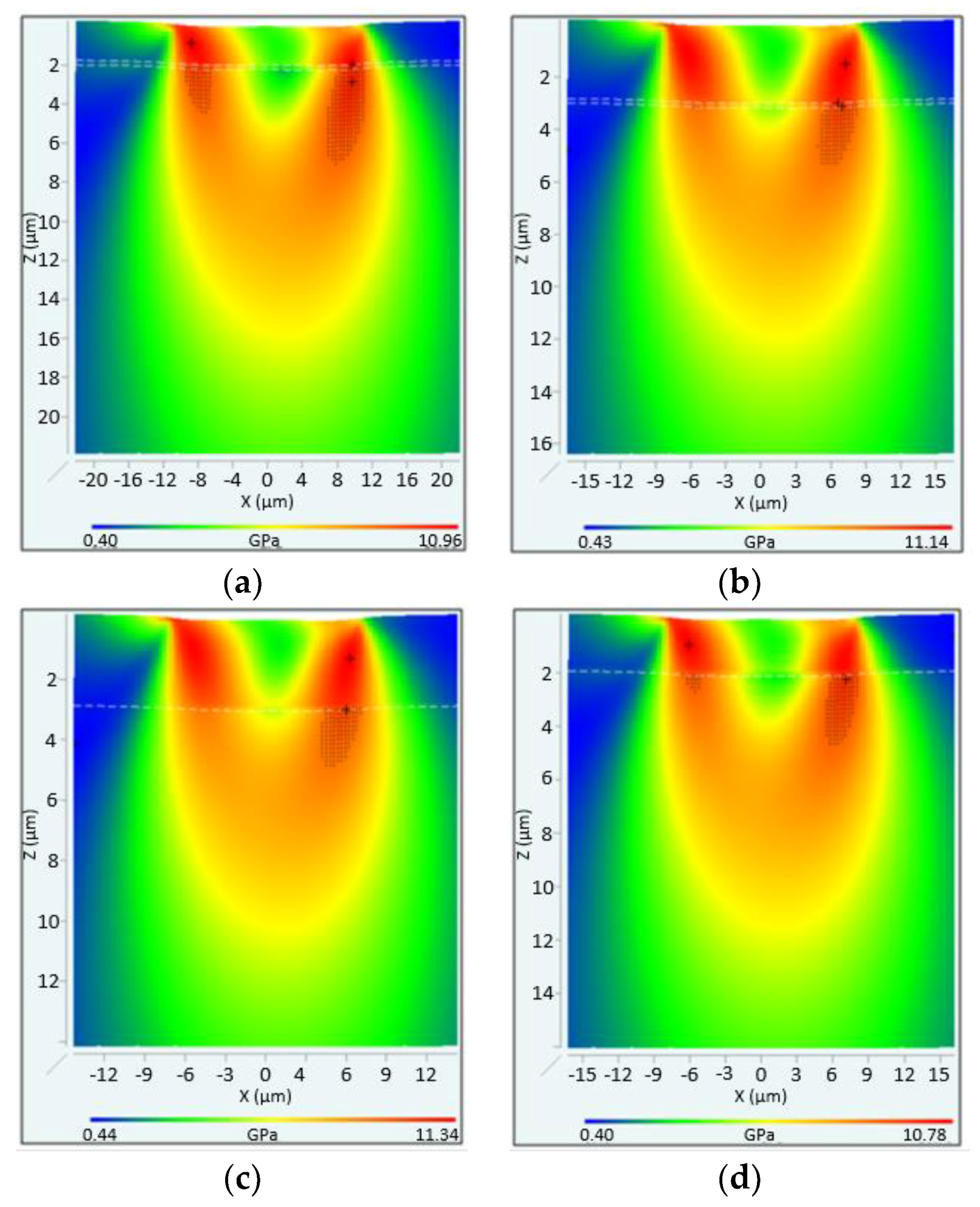
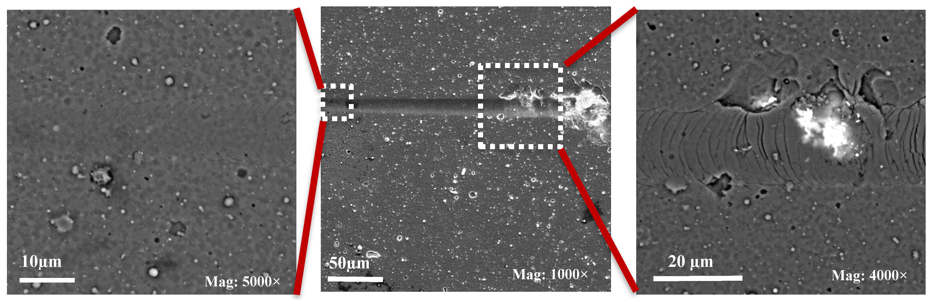
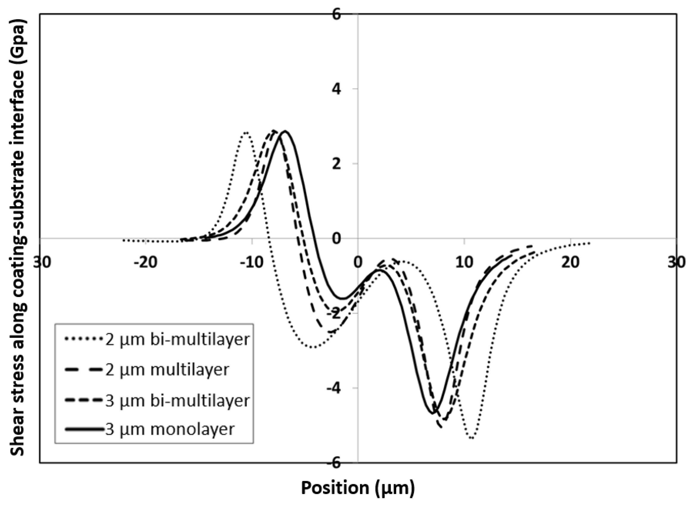
3.2.3. Analytical Modeling of Micro-Scratch Test Data

The analytical modeling approach taken utilizes George Pharr’s effective indenter concept for stress calculations [26,27,28]. The von Mises, tensile and shear stresses during the micro-scratch test were evaluated using the Scratch Stress Analyzer (SIO, Rugen, Germany), which uses a physical-based analytical methodology to determine simulated stress distributions. The input parameters to the physical-based analytical model are the mechanical properties of the coating and substrate i.e., H, E, H/Y (taken as 1.5 for the coatings and 2.5 for the cemented carbide substrate), their Poisson ratios, together with the applied load, scratch depth data, friction coefficient and probe radius in the micro-scratch test. For the analysis the friction coefficient was set to 0.2, which is typical for hard nitride coatings sliding against 25 µm diamond probes. For the modeling on the bi-multilayers the properties of the TiAlCrN sub-layer were taken as H = 28.2 GPa, E = 445 GPa.
The simulated von Mises stress distributions at the Lc2 failure are shown in Figure 5. The regions where the von Mises stress exceeds the yield stress are shaded. The maximum simulated stresses in the coating layers and the carbide substrate on the scratch center-axis at the Lc2 failure are summarized in Table 5. The position of maximum stress in the substrate were located on the substrate side of the interface in the case for all the coatings except for the 2 µm bi-multilayer system where the position has moved further into the substrate.
At Lc2 the substrate yields over a greater area for the thinner coatings, especially the 2 µm bi-multilayer but at Lc1 there is little difference. Since the substrate is overloaded more for the 2 µm bi-multilayer when it does fail (Figure 5a), it fails more dramatically, as is observed in the scratch depth data and through the microscope-based analysis of the scratch tracks.
Tensile stresses were high at the surface but low at the interface as the bonding layer stiffnesses were closely matched to that of the coatings. Peak tensile stresses were higher for the thicker coatings. The ~9–10 GPa tensile stresses at the rear of the probe result in arc cracks that are clearly visible in optical micrographs of the scratch tracks. SEM imaging revealed that the cracks start at the periphery of the scratch tracks before extending to produce complete arcs as the load increased (Figure 6).
The Lc2 failure requires the combination of high tensile stresses at the surface with significant weakening of the interface due to coating bending and substrate yield. This type of failure mechanism has previously been postulated to explain the failure of thicker coatings on cemented carbide in scratch tests by Schwarzer and co-workers [29]. The shear stress distribution along the coating-substrate interface is shown in Figure 7.
The maximum shear stresses acting at the interface were high and relatively insensitive to the applied load. At the Lc2 coating failure the shear stresses were of the order of 4 GPa. They were slightly greater on the 2 µm films, consistent with the thinner coatings being able to accommodate substrate deformation more effectively than the thicker ones [28]. Even higher values of von Mises stresses in scratch tests of a range of hard PVD coatings on WC-Co were reported [29].
Figure 8a presents the FIB (Focused Ion Beam)/TEM image of the nano-multilayer coating on the very edge of the cutting tool. It could be clearly seen that the nano-layers perfectly follow the shape of the sharp cutting edge. There is no visible damage within the entire coating layer despite significant bending of the nano-layers. It was shown previously [30] that the bending stresses in the individual nano-layers in a multilayer coating are less due to the accommodation of the bending radius that causes fracture in a monolayer coating of similar total thickness. At the same time, HRTEM (High Resolution Transmission Electron Microscopy, JEOL FS2200, JEOL USA, Inc., Peabody, MA, USA) analysis does not indicate a significant difference in nano-crystalline structure between 2 and 3 µm bi-multilayer coatings (Figure 8b,c).

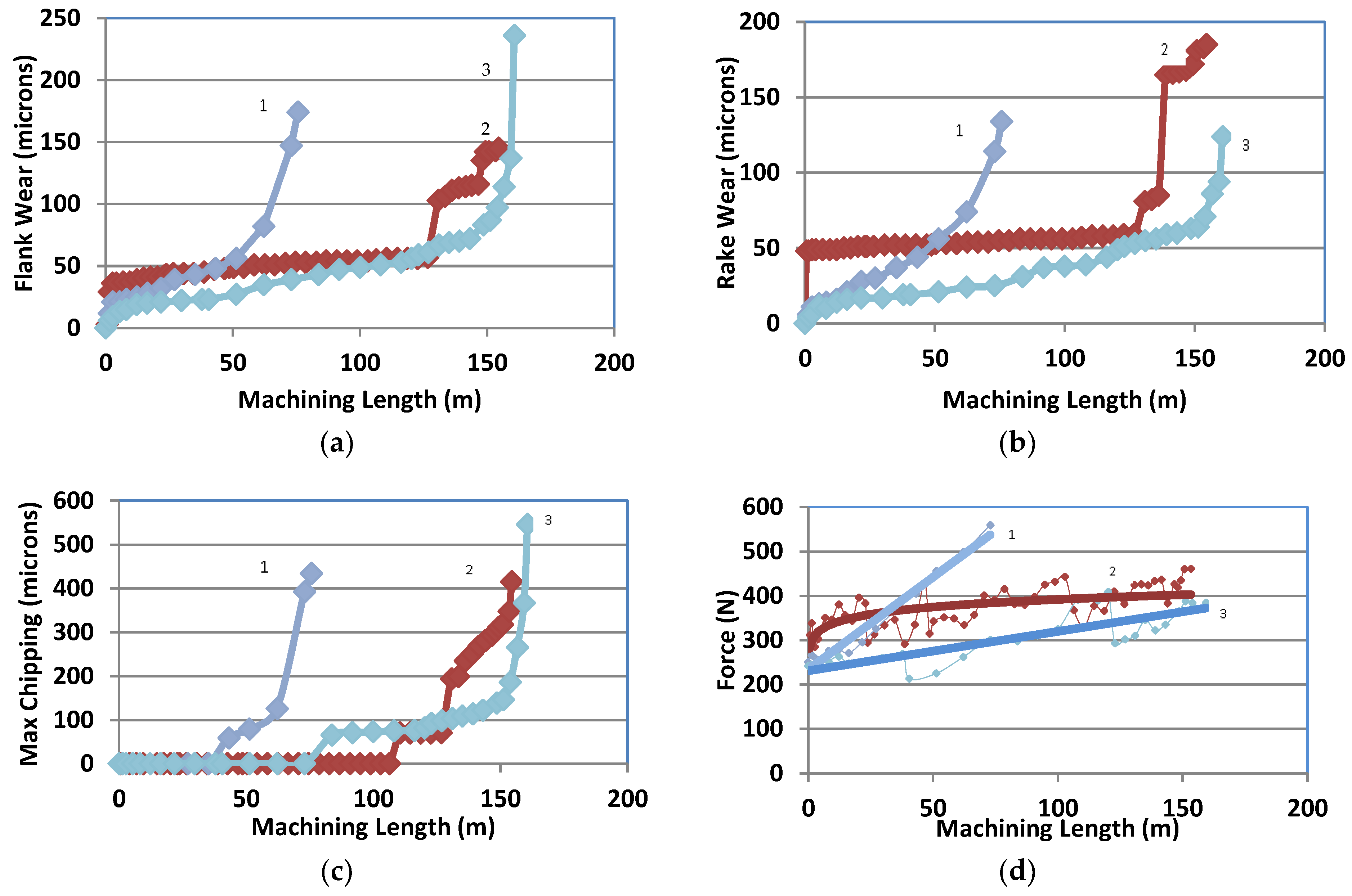
3.2.4. Tool Life and Wear Performance Studies

Tool life of the studied coatings is presented in Figure 9. Selected cutting conditions are extreme. To the best of our knowledge not much data is presented in the literature on the wear behavior of wear resistant multilayer coatings [31,32] under similar conditions. It was shown previously that under investigated extreme cutting conditions, when the temperatures as high as 1000–1100 °C and stresses are around 1.5–2 GPa, failure of the cutting tool is due to the flank wear, rake wear (with minimal buildup edge formation) and chipping [2,4,5]. To perform comprehensive wear studies of the tools with the investigated coatings all these characteristics have been evaluated.
Flank and rake wear data are shown in Figure 9a,b respectively. Chipping resistance is presented in Figure 9c. Average cutting forces are shown in Figure 9d. The monolayer coating has lower tool-life characteristics. Better wear characteristics and chipping behavior are directly related to its micro-mechanical properties, primarily load support and impact fatigue fracture resistance of the coatings studied. For the given cutting conditions and coating deposition parameters, multilayer 2-micron coating achieve a tool life of around 100 m in terms of machining length [4], whereas the best wear behavior is exhibited by the bi-multilayer coatings (i.e., around 60% increase in tool life for 3-micron bi-multilayer coating comparing to multilayer coating).
The wear evolution is more gradual on the bi-multilayers. This is similar to the impact behavior. The combination of low Lc1 and high Lc2, i.e., high scratch toughness, on the bi-multilayer is consistent with its behavior in the cutting test—there is some initial damage that is greater than the other coatings but then it shows good durability.
This bi-multilayer, 3 µm thick coating has lower cutting forces as well (Figure 9d). This is directly related to the ability of the coating to better protect its surface under operation. The better ability of the 3 microns thick coating to protect its surface is also related to the formation of protective tribo-ceramic film layer [17] (Figure 10). It was shown previously that a variety of thermal barrier tribo-films are forming on the surface of the coating under operation [16,17]. Effective replenishment of these films is strongly related to the surface damage of the coating layer. The coating with lower intensity of surface damage can be a better environment for the dynamic tribo-films to be formed, worn out and rejuvenated again as a result of friction and interaction with the environment. That is why bi-multilayer coatings with improved micro-mechanical characteristics, indicating lower damage of the coating layer show better surface protection (Figure 10).
The mechanical behavior outlined above affects the ability of the coating layer to self-protect its surface under operation through the formation of protective tribo-ceramic films on the friction surface (Figure 10). The surface that undergoes less damage under operation has the ability to form a higher amount of thermal barrier ceramic tribo-films (Figure 10), such as sapphire [16] and mullite [16]. This critically improves the wear performance of the coating layer. Therefore, the tool with better protection has a higher tool life (Figure 9). As was shown previously [17] non-protective TiOx and lubricious CrOx tribo-films also form but their amount is below 10% and therefore they are believed to be less critical to the overall tool life than the sapphire and mullite tribo-films.

4. Conclusions

Detailed studies of the structure and properties of a number of different TiAlCrSiYN-based coatings (monolayer, multilayer, bi-multilayer, bi-multilayer with increased number of alternating nano-layers) have been performed. The wear performance of the TiAlCrSiYN-based coating was improved through optimization of their architecture. The relationship between the coatings’ structure characterized by different methods such as XRD, SEM, TEM and micro-mechanical characteristics (hardness, elastic modulus and their ratios; nano-impact, scratch characteristics) and their tool life was established. It was shown by XPS analysis that the coating layer with lower intensity of surface damage is a better environment for the formation of the dynamic nano-scale tribo-films on the friction surface that result in improved surface protection under extreme conditions. It could be concluded that a noticeable improvement in the wear behavior could be achieved during high-performance dry machining of hardened tool steels through the incorporation of interlayer in multilayer coating architectures with a realization of better micro-mechanical characteristics of the coatings.

Acknowledgments

The authors acknowledge the financial support from the Natural Sciences and Engineering Research Council of Canada (NSERC) and the Canadian Network for Research and Innovation in Machining Technology (CANRIMT). The authors also acknowledge the MMRI for the use of its facilities.

Author Contributions

Shahereen Chowdhury designed and performed experiments on machining and micro-mechanical characterization; Ben D. Beake performed experiments and modeling on micro-mechanical characterization; Kenji Yamamoto designed the coatings and made XRD characterizations; Bipasha Bose performed micro-mechanical characterization and evaluating of results; Myrian Aguirre performed TEM characterization; German S. Fox-Rabinovich analyzed, discussed the results and co-wrote the paper; and Stephen C. Veldhuis directed the experiments and analyzed the data.

Conflicts of Interest

The authors declare no conflicts of interest.

References

  1. Bouzakis, K.-D.; Michailidis, N.; Skordaris, G.; Bouzakis, E.; Biermann, D.; M’Saoubi, R. Cutting with coated tools: Coating technologies, characterization methods and performance optimization. CIRP Ann. Manuf. Technol. 2012, 61, 703–723. [Google Scholar] [CrossRef]
  2. Fox-Rabinovich, G.S.; Yamamoto, K.; Beake, B.D.; Kovalev, A.I.; Aguirre, M.H.; Veldhuis, S.C.; Dosbaeva, G.K.; Wainstein, D.L.; Biksa, A.; Rashkovskiy, A. Emergent behavior of nano-multilayered coatings during dry high-speed machining of hardened tool steels. Surf. Coat. Technol. 2010, 204, 3425–3435. [Google Scholar] [CrossRef]
  3. Fox-Rabinovich, G.S.; Yamamoto, K.; Beake, B.D.; Gershman, I.S.; Kovalev, A.I.; Aguirre, M.H.; Veldhuis, S.C.; Dosbaeva, G.; Endrino, J.L. Hierarchical adaptive nano-structured PVD coatings for extreme tribological applications: the quest for non-equilibrium states and emergent behavior. Sci. Technol. Adv. Mater. 2012, 13, 043001. [Google Scholar] [CrossRef] [PubMed]
  4. Fox-Rabinovich, G.S.; Endrino, J.L.; Agguire, M.H.; Beake, B.D.; Veldhuis, S.C.; Kovalev, A.I.; Gershman, I.S.; Yamamoto, K.; Losset, Y.; Wainstein, D.L.; et al. Mechanism of adaptability for the nano-structured TiAlCrSiYN-based hard PVD coatings under extreme frictional conditions. J. Appl. Phys. 2012, 111, 064306. [Google Scholar] [CrossRef]
  5. Fox-Rabinovich, G.S.; Beake, B.D.; Yamamoto, K.; Aguirre, M.H.; Veldhuis, S.C.; Dosbaeva, G.; Elfizy, A.; Biksa, A.; Shuster, L.S. Structure, properties and wear performance of nano-multilayered TiAlCrSiYN/TiAlCrN coatings during machining of Ni-based aerospace super alloys. Surf. Coat. Technol. 2010, 204, 3698–3706. [Google Scholar] [CrossRef]
  6. Beake, B.D.; Fox-Rabinovich, G.S.; Losset, Y.; Yamamoto, K.; Agguire, M.H.; Veldhuis, S.C.; Endrino, J.L.; Kovalev, A.I. Why can TiAlCrSiYN-based adaptive coatings deliver exceptional performance under extreme frictional conditions? Faraday Discuss. 2012, 156, 267–277. [Google Scholar] [CrossRef] [PubMed]
  7. Bouzakis, K.-D.; Makrimallakis, S.; Katirtzoglou, G.; Skordaris, G.; Gerardis, S.; Bouzakis, E.; Leyendecker, T.; Bolz, S.; Koelker, W. Adaption of graded Cr/CrN-interlayer thickness to cemented carbide substrates’ roughness for improving the adhesion of HPPMS PVD films and the cutting performance. Surf. Coat. Technol. 2010, 205, 1564–1570. [Google Scholar] [CrossRef]
  8. Voevodin, A.A.; Zabinski, J.S.; Muratore, C. Recent advances in hard, tough, and low friction nanocomposite coatings. Tsinghua Sci. Technol. 2005, 10, 665–679. [Google Scholar] [CrossRef]
  9. Skordaris, G.; Bouzakis, K.-D.; Charalampous, P.; Bouzakis, E.; Paraskevopoulou, R.; Lemmer, O.; Bolz, S. Brittleness and fatigue effect of mono- and multilayer PVD films on the cutting performance of coated cemented carbide inserts. CIRP Ann. Manuf. Technol. 2014, 63, 93–96. [Google Scholar] [CrossRef]
  10. Chan, K.S.; He, M.Y.; Hutchinsson, J.W. Cracking and stress redistribution in ceramic layered composites. J. Mater. Sci. Eng. 1993, 167, 57–64. [Google Scholar] [CrossRef]
  11. He, M.Y.; Evens, A.G.; Hutchinsson, J.W. Crack deflection at an interface between dissimilar elastic materials: Role of residual stresses. Int. J. Solids Struct. 1994, 31, 3443–3455. [Google Scholar] [CrossRef]
  12. Chen, J.; Li, H.; Beake, B.D. Load sensitivity in repetitive nano-impact testing of TiN and AlTiN coatings. Surf. Coat. Technol. 2016, 308, 289–297. [Google Scholar] [CrossRef]
  13. Astakhov, V.P.; Davim, J.P. Tools (geometry and material) and tool. In Machining: Fundamentals and Recent Advances; Davim, J.P., Ed.; Springer: London, UK, 2008; pp. 29–57. [Google Scholar]
  14. Hassani, S.; Bielawski, M.; Beres, W.; Martinu, L.; Balazinski, M.; Sapieha, J.E.K. Predictive tools for the design of erosion resistant coatings. Surf. Coat. Technol. 2008, 203, 204–210. [Google Scholar] [CrossRef]
  15. Bruet, B.J.F.; Song, J.; Boyce, M.C.; Ortiz, C. Materials design principles of ancient fish armour. Nat. Mater. 2008, 7, 748–756. [Google Scholar] [CrossRef] [PubMed]
  16. Fox-Rabinovich, G.; Kovalev, A.; Aguirre, M.H.; Yamamoto, K.; Gershman, I.; Rashkovskiy, A.; Endrino, J.L.; Beake, B.; Veldhuis, S.; Dosbaeva, G.; et al. Evolution of self-organization in nano-structured PVD coatings under extreme tribological conditions. Appl. Surf. Sci. 2014, 297, 22–32. [Google Scholar] [CrossRef]
  17. Fox-Rabinovich, G.; Kovalev, A.; Veldhuis, S.; Yamamoto, K.; Endrino, J.L.; Gershman, I.S.; Rashkovskiy, A.; Aguirre, M.H.; Wainstein, D.L. Spatio-temporal behaviour of atomic-scale tribo-ceramic films in adaptive surface engineered nano-material. Sci. Rep. 2015, 5, 8780. [Google Scholar] [CrossRef] [PubMed]
  18. Welzel, U.; Ligot, J.; Lamparter, P.; Vermeulen, A.C.; Mittemeijer, E.J. Stress analysis of polycrystalline thin films and surface regions by X-ray diffraction. J. Appl. Crystallogr. 2005, 38, 1–29. [Google Scholar] [CrossRef]
  19. Ming, Z.; Hairlin, S.; Jiawen, H. Elastic modulus of TiN films investigated with Kroner model and X-ray diffraction. Trans. Nonferrous Met. Soc. Chin. 2001, 1, 63–66. [Google Scholar]
  20. Yamamoto, K.; Kujime, S.; Fox-Rabinovich, G. Effect of alloying element (Si,Y) on properties of AIP deposited (Ti,Cr,Al)N coating. Surf. Coat. Technol. 2008, 203, 579–583. [Google Scholar] [CrossRef]
  21. Yamamoto, K.; Sato, T.; Takahara, K.; Hanaguri, K. Properties of (Ti,Cr,Al)N coatings with high Al content deposited by new plasma enhanced arc-cathode. Surf. Coat. Technol. 2003, 174–175, 620–626. [Google Scholar] [CrossRef]
  22. Carvalho, N.J.M.; Zoestbergen, E.; Kooi, B.J.; de Hosson, J.T.M. Stress analysis and microstructure of PVD monolayer TiN and multilayer TiN/(Ti,Al)N coatings. Thin Solid Films 2003, 429, 179–189. [Google Scholar] [CrossRef]
  23. Fox-Rabinovich, G.S.; Veldhuis, S.C.; Dosbaeva, G.K.; Yamamoto, K.; Kovalev, A.I.; Wainstein, D.L.; Gershman, I.S.; Shuster, L.S.; Beake, B.D. Nanocrystalline coating design for extreme applications based on the concept of complex adaptive behavior. J. Appl. Phys. 2008, 103, 083510. [Google Scholar] [CrossRef]
  24. Mayrhofer, P.H.; Mitterer, C.; Hultman, L.; Clemens, H. Microstructural design of hard coatings. Prog. Mater. Sci. 2006, 51, 1032–1114. [Google Scholar] [CrossRef]
  25. Bielawski, M. Residual stress control in TiN/Si coatings deposited by unbalanced magnetron sputtering. Surf. Coat. Technol. 2006, 200, 3987–3995. [Google Scholar] [CrossRef]
  26. Schwarzer, N.; Pharr, G.M. On the evaluation of stresses during nanoindentation with sharp indenters. Thin Solid Films 2004, 469–470, 194–200. [Google Scholar] [CrossRef]
  27. Schwarzer, N.; Chudoba, T.; Pharr, G.M. On the evaluation of stresses for coated materials during nanoindentation with sharp indenters. Surf. Coat. Technol. 2006, 200, 14–15. [Google Scholar] [CrossRef]
  28. Schwarzer, N. Analysing nanoindentation unloading curves using pharr’s concept of the effective indenter shape. Thin Solid Films 2006, 494, 168–172. [Google Scholar] [CrossRef]
  29. Schwarzer, N.; Duong, Q.-H.; Bierwisch, N.; Favaro, G.; Fuchs, M.; Kempe, P.; Widrig, B.; Ramm, J. Optimization of the scratch tests for specific coating designs. Surf. Coat. Technol. 2011, 206, 1327–1335. [Google Scholar] [CrossRef]
  30. Matthews, A.; Jones, R.; Dowey, S. Modelling the deformation behaviour of multilayer coatings. Tribol. Lett. 2001, 11, 103–106. [Google Scholar] [CrossRef]
  31. Hovsepian, P.E.; Reinhard, C.; Ehiasarian, A.P. CrAlYN/CrN superlattice coatings deposited by the combined high power impulse magnetron sputtering/unbalanced magnetron sputtering technique. Surf. Coat. Technol. 2006, 201, 4105–4110. [Google Scholar] [CrossRef]
  32. Veprek, S.; Veprek-Heijman, M.J.G. Industrial applications of superhard nanocomposite coatings. Surf. Coat. Technol. 2006, 202, 5063–5073. [Google Scholar] [CrossRef]
Figure 1. TEM (transmission electron microscope, JEOL FS2200, JEO USA, Inc., Peabody, MA, USA) image of FIB cross-section of TiAlCrSiYN-based coatings: (a) TiAlCrSiYN monolayer; (b) TiAlCrSiYN/TiAlCrN multilayer; (c) TiAlCrSiYN/TiAlCrN bi-multilayer. Thickness of alternating nano-layers in multilayered coatings is 20–40 nm, thickness of TiAlCrN sublayer is 100 nm.
Coatings 08 00059 g001aCoatings 08 00059 g001b
Figure 2. X-ray diffractograms of different TiAlCrSiYN-based coating architectures with different thickness.
Coatings 08 00059 g002
Figure 3. Short-term impact fatigue fracture resistance data at 20 mN, 30 s for the studied coatings: (a) monolayer, 3 µm; (b) bi-multilayer, 2 µm; (c) bi-multilayer, 3 µm.
Coatings 08 00059 g003aCoatings 08 00059 g003b
Figure 4. Impact fatigue fracture resistance at 25–30 mN, 300 s for the studied coatings: (a) monolayer, 3 µm; (b) bi-multilayer, 2 µm; (c) bi-multilayer, 3 µm.
Coatings 08 00059 g004
Figure 5. Simulated von Mises stress distributions at Lc2 failure for: (a) bi-multilayer, 2 µm; (b) bi-multilayer, 3 µm; (c) monolayer, 3 µm; (d) multilayer, 2 µm. The scratch direction is from left to right.
Coatings 08 00059 g005
Figure 6. SEM images of a micro-scratch test on the 3 µm bi-multilayer, with higher magnification images of the deformation at the Lc1 and Lc2 failures.
Coatings 08 00059 g006
Figure 7. Simulated interfacial shear stresses at Lc2 failure. The scratch direction is from left to right.
Coatings 08 00059 g007
Figure 8. FIB/TEM images of the multilayer TiAlCrSiYN/TiAlCrN coatings: (a) FIB cross-section of multilayer TiAlCrSiYN/TiAlCrN coating on the cutting edge; (b) HRTEM with SAED (selected area electron diffraction pattern) diffraction patterns of 2 µm bi-multilayer coating; (c) TEM-HRTEM with SAED diffraction patterns of 3 µm bi-multilayer coating.
Coatings 08 00059 g008
Figure 9. Tool-life data of the studied coatings vs. length of cut (m): (a) flank wear; (b) rake wear; (c) chipping intensity; (d) average cutting forces. 1: TiCrAlSiYN monolayer, 3 µm; 2: TiCrAlN/TiCrAlSiYN bi-multilayer, 2 µm; 3: TiCrAlN/TiCrAlSiYN bi-multilayer, 3 µm.
Coatings 08 00059 g009
Figure 10. XPS (X-ray photoelectron spectroscopy, Physical Electronics (PHI) Quantera II spectrometer, Physical Electronics, Inc., Chanhassen, MN, USA) data for tribo-films formed on the worn surface of bi-multilayer TiAlCrSiYN/TiAlCrN thin film coating with different thickness (of 2 and 3 µm) during running-in stage (after machining of 30 m).
Coatings 08 00059 g010
Table 1. Cutting parameters used for the tool-life evaluation.
MachineToolCutting Parameters
Speed (m/min)Feed (mm/tooth)Axial Depth (mm)Radial Depth (mm)Coolant
Three-axis vertical milling center (Matsuura FX-5, Matsuura Machinery Corporation1-1, Fukui-City, Japan)Mitsubishi carbide ball nose end mills C-2SB, D = 10 mm6000.0650.6Dry conditions
Table 2. Residual stress values in the studied coatings.
CoatingArchitectureStress (GPa)
TiCrAlN monolayerMonolayer, 3 microns thick−5.65 ± 0.3
TiCrAlSiYN monolayerMonolayer, 3 microns thick−6.17 ± 1.2
TiCrAlN/TiCrAlSiYN multilayerMultilayer, 2 microns thick−7.09 ± 0.6
TiCrAlN/TiCrAlSiYN bimultilayerBi-multilayer, 2 microns thick−6.99 ± 0.5
TiCrAlN/TiCrAlSiYN bimultilayerBi-multilayer, 3 microns thick−6.50 ± 0.4
Table 3. Micro-mechanical properties of the studied coatings.
CoatingThickness, (microns)Hardness (GPa)Elastic Modulus (GPa)Plasticity IndexH/E RatioH3/E2 RatioCPRs Parameter Lc1(Lc2Lc1)
Ti0.2Al0.55Cr0.2Si0.03Y0.02N Monolayer329.6 ± 4.5489.80.470.0600.1081.6
Ti0.25Al0.65Cr0.1N Monolayer325.9 ± 4.8430.70.490.0600.0934.8
Ti0.2Al0.55Cr0.2Si0.03Y0.02N/
Ti0.25Al0.65Cr0.1N Multilayer [5]
228.4 ± 4.5429.00.460.0660.1241.9
Ti0.2Al0.55Cr0.2Si0.03Y0.02N/
Ti0.25Al0.65Cr0.1N Bi-Multilayer
231.6 ± 2.5432.70.430.0730.1695.8
Ti0.2Al0.55Cr0.2Si0.03Y0.02N/
Ti0.25Al0.65Cr0.1N Bi-Multilayer
330.9 ± 2.7474.60.450.0650.1313.2
Table 4. Short time (30 s) and final depth (300 s) impact fatigue data (20–30 mN).
CoatingThickness (microns)Final Depth (Mean) (microns)
30 s300 s
Ti0.2Al0.55Cr0.2Si0.03Y0.02N-Monolayer31.4 ± 0.42.2 ± 0.5
Ti0.25Al0.65Cr0.1N-Monolayer32.14 ± 0.3
Ti0.2Al0.55Cr0.2Si0.03Y0.02N/Ti0.25Al0.65Cr0.1N-Multilayer21.8 ± 0.3
Ti0.2Al0.55Cr0.2Si0.03Y0.02N/Ti0.25Al0.65Cr0.1N-Bi-Multilayer20.93 ± 0.31.8 ± 0.3
Ti0.2Al0.55Cr0.2Si0.03Y0.02N/Ti0.25Al0.65Cr0.1N-Bi-Multilayer30.84 ± 0.11.4 ± 0.3
Table 5. Simulated maximum von Mises stresses from the micro-scratch test.
CoatingApplied Load or Critical LoadMaximum Normal Stress at Surface (GPa)Maximum von Mises Stress in Coating (GPa)Maximum von Mises Stress in Interlayer (GPa)Maximum von Mises Stress in Substrate (GPa)
2 µm
bi-multilayer
2 N8.910.910.69.8
Lc29.211.011.010.2
3 µm
bi-multilayer
2 N10.211.610.49.7
Lc29.711.110.59.8
3 µm monolayer2 N10.111.59.8
Lc29.911.39.7
2 µm multilayer2 N9.211.09.8
Lc29.010.89.8

