
Microstructure and Properties after Friction Stir Processing of Twin-Roll Cast Al–Mn–Cu–Be Alloy
by
 , ,
, ,
Matjaž Macerl
1,2, 
Franc Zupanič
2,
Lara Hočuršćak
2,
Damjan Klobčar
3,
András Kovács
4 and
Tonica Bončina
2,* 1
Srednja Tehniška in Poklicna Šola Trbovlje, Šuštarjeva Kolonija 7a, SI-1420 Trbovlje, Slovenia
2
Faculty of Mechanical Engineering, University of Maribor, Smetanova Ulica 17, SI-2000 Maribor, Slovenia
3
Faculty of Mechanical Engineering, University of Ljubljana, Aškerčeva Cesta 6, SI-1000 Ljubljana, Slovenia
4
Ernst Ruska-Centre for Microscopy and Spectroscopy with Electrons, Forschungszentrum Jülich GmbH, Wilhelm-Johnen-Straße, D-52428 Juelich, Germany
*
Author to whom correspondence should be addressed.
Crystals 2022, 12(5), 630; https://doi.org/10.3390/cryst12050630
Submission received: 30 March 2022
/
Revised: 18 April 2022
/
Accepted: 25 April 2022
/
Published: 27 April 2022
(This article belongs to the Special Issue Microstructure Characterization and Design of Alloys)
Abstract
:We studied the effect of friction stir processing (FSP) on the microstructure and properties of high-speed twin-roll cast strips made of an experimental Al–Mn–Cu–Be alloy. The samples were examined using light, scanning, and transmission electron microscopy, microchemical analysis, X-ray diffraction, and indentation testing. During FSP, the rotational speed varied, while other parameters remained constant. The uniformity of the microstructure increased with the growing rotational speed. In the stir zone, several processes took place, and the most important were: recrystallisation of the matrix grains, fragmentation of the primary intermetallic particles Al15Mn3Be2 and their more uniform distribution in the stir zone, fracture, and dispersion of the eutectic icosahedral quasicrystalline phase (IQC), transformation of tiny Al15Mn3Be2 and IQC particles into the τ1-Al26Mn6Cu4 phase and precipitation of Al–Mn–Cu precipitates. In the thermomechanically affected zone, new dislocations formed as well as dispersion of the IQC eutectic phase and recrystallisation of the matrix grains. In the heat-affected zone, dissolution of θ’-Al2Cu precipitates occurred. The hardness variation was not severe between the stir and heat-affected zones.
1. Introduction
Aluminium alloys are crucial in the modern world. Their use has been increasing for decades due to their low density and outstanding specific strength and modulus [1]. One of the main disadvantages of conventional aluminium alloys is their relatively low heat resistance, since most alloys lose their strength when heated above 250 °C [2]. We developed Al–Mn–Cu–X alloys, which are experimental precipitation-hardened aluminium alloys. They possess a high strength at room temperature and high creep resistance at elevated temperatures [3]. They could be used as a heat resistance material in construction, for fire-resistant buildings, and bridges. In such applications, weldability is an essential technological property [4]. One of the possibilities is to use friction stir welding to join parts of these alloys together as well as to join these alloys with other aluminium alloys [5,6].
The Al–Mn–Cu–X alloys are rather complex. In alloys of Al–Mn–Cu–Be, a very high density of icosahedral quasicrystalline (IQC) precipitates can form during artificial ageing (T5 treatment; artificial ageing after manufacturing) in the temperature range between 300 °C and 450 °C. In addition, θ’-Al2Cu, T-Al20Mn3Cu2, decagonal quasicrystalline, and Be4Al(Cu,Mn) precipitates can form in other temperatures ranges or longer ageing times [7].
Casting of these alloys by single- or twin-roll casting can enable manufacturing semi-products of these alloys in larger quantities. The casting speed of bands (3–5 mm thick, 100 mm wide) can be up to 60 m/min [8]. However, they have a non-uniform as-cast microstructure [9].
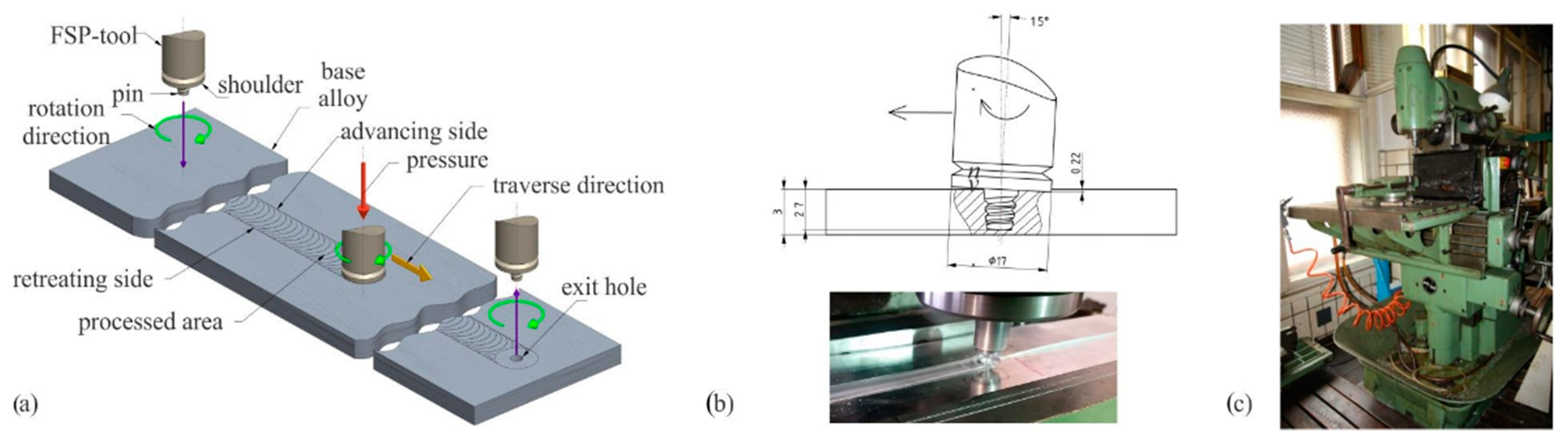
The uniformity of the as-cast bands can be considerably improved by friction stir processing (Figure 1). Friction stir processing (FSP) is a thermomechanical process in which material is exposed to extreme plastic deformation and high temperature due to the transformation of mechanical work to heat [10]. There are several regions in the FSP-treated material: stir zone (SZ), thermomechanically affected zone (TMAZ), and heat-affected zone (HAZ). Even in each of these zones, different microstructures can form due to differences in the degree of plastic deformation and thermal history. It is important to stress that microstructures are similar to those obtained by friction stir welding.
The activity in the field of friction stir processing/welding is extremely high. Heidarzadeh et al. [10] provided a review on microstructural evaluation, while Kumar and Kumar [11] conducted a review regarding the fabrication of surface composites using FSP. Puviyarasan et al. [12] studied the effect of process parameters on the mechanical properties of AA 6061-T6. The FSP and FSW of flat semi-products is an established process, so some studies have investigated the possible application of FSW for tubes and pipes [13,14]. Tao et al. [15] found that post weld artificial ageing strongly enhanced the mechanical properties of AA 2198-T8 aluminium alloys. The microstructure and mechanical properties also depend on the tool shape, which should be optimised for the specific materials and shape of pieces to be processed [16,17,18,19,20]. The efficiency and optimisation of FSP and FSW is intended to be improved. Thus, a lot of energy has been devoted to the development of analytical and numerical models that takes into account the thermal field, material flow, heat generated, distributed and losses, viscoplastic behaviour, and high-speed plastic deformation [21,22].
The initial material for the study was an Al–Mn–Cu–Be alloy produced by twin-roll casting [9]. It has a non-uniform microstructure, possessing coarse intermetallic particles throughout the strip, especially at its centre. These particles can be crushed and uniformly distributed in the microstructure to produce an in situ composite, which may have some advantages compared to other in situ composites [23,24,25]. However, the main scientific objective was to determine the effect of friction stir processing on the microstructure and properties of the selected aluminium alloy. There is no information in the available literature about the FSP of the Al–Mn–Cu–X alloys. Thus, investigating the FSP treated Al–Mn–Cu–X alloys will produce new information for the scientific community.
2. Materials and Methods
Strips (3 mm thickness, 60 mm width) of an experimental Al–Mn–Cu–Be alloy were produced by high-speed twin-roll casting with a casting speed of 30 m min−1. The composition of the alloy is presented in Table 1. More details regarding the casting processes are given in [9].
Afterwards, the strips were treated by FSP using a universal milling machine Prvomajska ALG 200, Zagreb, Croatia. The tool shoulder diameter was 17 mm, pin diameter was 6 mm, and its length was 2.7 mm. Parameters are given in Table 2, while the process scheme is presented in Figure 1a. The tests were performed at constant tool tilt angle of 1.5°, constant traverse speed of 46 mm/min and with two rotation speeds. The rotation speed of 95 min−1 was the minimum speed at which a high-quality processed region was achieved without any macroscopic defects. The other rotation speed was ten times higher, 950 min−1, to obtain significant microstructure variations by higher energy input. The samples were labelled with FSP 95 and FSP 950 for the rotation speed of 95 min−1 and 950 min−1, respectively.
Samples were prepared using metallography to make the FSP-zones visible. The samples for light (LM) and scanning electron (SEM) microscopy were mechanically ground and polished. After final polishing using a 3 μm diamond paste, the microstructure was revealed by chemical etching with Weck’s reagent consisting of 2 g KMnO4 (Merck KGaA, Darmstadt, Germany), 1 g NaOH (Merck KGaA, Darmstadt, Germany), and 50 mL of distilled water. The samples were then examined using a light microscope Nikon EPIPHOT 300 (Tokyo, Japan), and scanning electron microscopes (SEM) Sirion 400 NC and Quanta 200 (FEI, Eindhoven, the Netherlands). During the SEM, we also carried out microchemical analysis using energy dispersive spectroscopy (EDS, Oxford Analytical, Bicester, UK).
Electron transparent specimens for transmission electron microscopy (TEM) were prepared using focused Ga ion beam (FIB) sputtering in a dual-beam scanning electron microscope (FEI Helios 400; FEI, Eindhoven, The Netherlands). A standard lift-out preparation approach was followed by attaching the TEM specimen to a copper Omniprobe support grid (Oxford Analytical, Bicester, UK). The preparation artefacts were reduced by low-energy (<1 keV) Ar ion milling using a Fischione 1040 system (E.A. Fischione Instruments, Inc., Export, PA 15632, USA). Microstructure and chemical composition analyses were carried out using an electron probe aberration-corrected scanning TEM (STEM), equipped with an in-column energy-dispersive X-ray spectroscopy (EDS) system (FEI Titan 80–200, Super-X, Eindhoven, The Netherlands). The STEM images and EDS spectrum images were collected and processed using the commercial ThermoFisher Velox software (Thermo Fisher Scientific, Waltham, MA, USA).
X-ray diffraction was conducted at synchrotron Elettra (Elettra, Trieste, Italy) using X-rays with a wavelength of 0.0999996 nm. XRD images were taken in transmission mode at 24 °C. The samples were in the form of thin plates with thicknesses of 200–300 μm. The sampling area was 500 × 500 μm2. The 2D-images were collected using a Dectris Pilatus 2M camera (Dectris Ltd., Baden-Daettwil, Switzerland) at a working distance of 100 mm. LaB6 powder was used to calibrate the image. The 2D images were transformed into X-ray patterns: intensity I versus diffraction angle 2θ by using software Fit2D (ESFR, Grenoble, France). Programs CrystalMaker 9.2.8 (CrystalMaker Software Ltd., Oxfordshire, UK) and CheckCell (Jean Laugier and Bernard Bochu, Saint-Martin-d’Hères, France) were used for the data processing and analysis of the results.
Indentation tests were carried out using a Nano Test Vantage (Micro Materials Limited, Wrexham, UK). The indentation load was provided with an electromagnetic force, and the indentation displacement was measured by the change in the capacitance. A Vickers indenter (Micro Materials Limited, Wrexham, UK) was used to measure hardness across the processes area (maximum load 4903 mN, loading, holding at maximum load and unloading each 10 s). Indentation properties at specific areas were measured using a Berkovich indenter (Micro Materials Limited, Wrexham, UK) with the following parameters: maximum load 10 mN, loading, holding at maximum load and unloading each 10 s; 25 measurements at each location.
3. Results
3.1. The Effect of FSP on the Modification of the As-Cast Structure
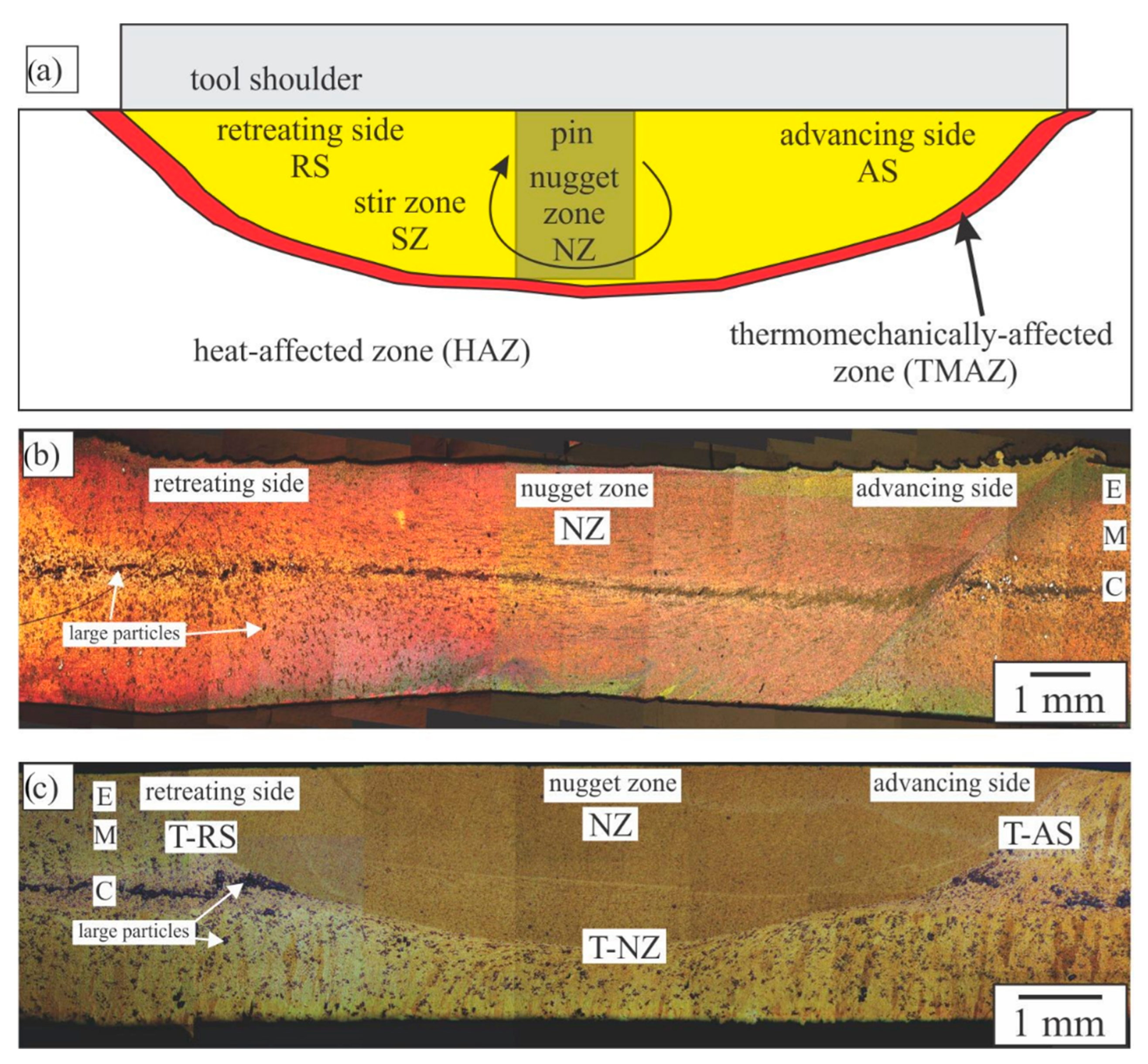
Figure 2a shows schematically different regions in the FSP strips, while Figure 2b,c shows macrostructures of the FSP strips processed with the slowest and fastest rotation speeds. The matrix consisted of aluminium-rich solid solution αAl incorporating different phases. The darker areas, indicated by the arrows, are large individual or agglomerated intermetallic particles, predominantly the quasicrystalline approximant phase Al15Mn3Be2. Other phases were much smaller and could not be seen at this magnification.
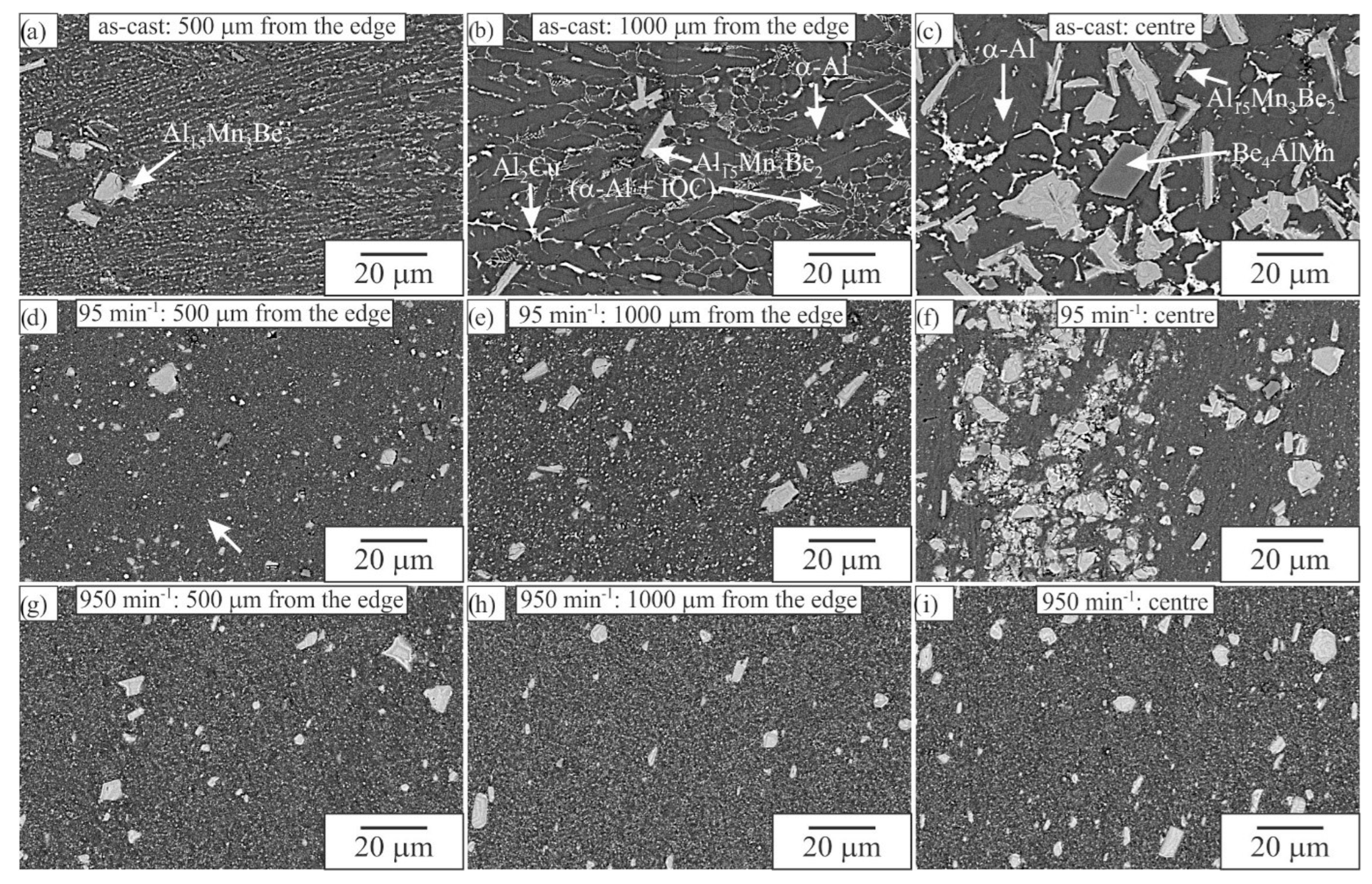
The initial as-cast microstructure was not uniform and could be seen on both sides of the processed zone. Since it was investigated in detail in our previous paper [9], only basic information is given here. At the roll side, a thin outer equiaxed zone formed (E in Figure 2), which was followed by elongated grains (region M, thickness around 900 μm) with the size 238 ± 80 µm × 63 ± 27 µm. In the central region (region C), small α-Al grains were present (linear intercept length was 7.3 ± 1.3 µm), with approximately 20% of large Al15Mn3Be2 agglomerated into a central belt, often incorporating Be4Al(Mn,Cu) particles. The larger particles were dispersed throughout the thickness of the twin-roll-cast strip; however, they were more abundant at the centre. In Figure 3a–c, all other phases present in the as-cast condition are indicated (the matrix Al-rich solid solution α-Al, tetragonal θ-Al2Cu, icosahedral quasicrystalline phase IQC, cubic Be4Al(Mn,Cu) and hexagonal quasicrystalline approximant Al15Mn3Be2).
There were several zones in the FSP-treated material: stir or mix zone (SZ), thermomechanically affected zone (TMAZ), and heat-affected zone (HAZ). Their size and distribution strongly depend on the FSP parameters. There were also three subzones in the stir zone: nugget zone (NZ), advancing side (AS), and retreating side (RS), all possessing slightly different microstructures (Figure 2).
FSP caused considerable refinement of the initial microstructure, which became more uniform (Figure 2 and Figure 3). The reference as-cast microstructures at the three areas are given in Figure 3a–c. During FSP, large primary intermetallic particles crashed and were more uniformly distributed within the Al-rich solid solution matrix. The same happened to the quasicrystalline eutectic phase (bright phase in Figure 3b). The most important observation was that a fine dispersion of particles was present in the Al-rich solid solution within the stir zone (Figure 3d–i). The microstructural investigation using high-resolution SEM indicated that the particle sizes ranged between a few 10 nm and a few μm. Some of those particles originated from the mechanical disintegration of the particles present in the as-cast condition, while others precipitated during FSP. SEM did not allow a clear distinction between the crashed particles and precipitates.
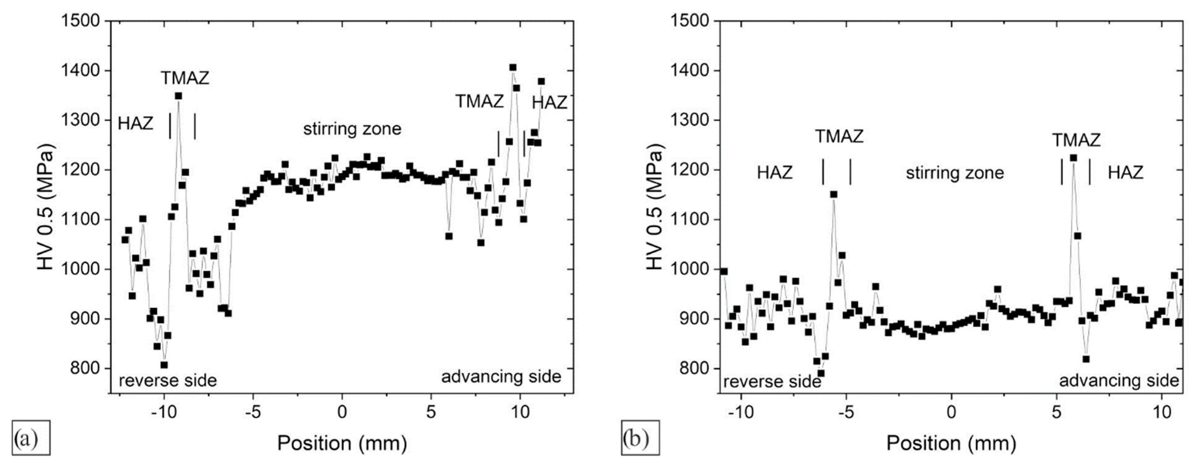
Figure 4 shows the variation of Vickers indentation hardness for both casting conditions. In both cases, the highest hardness coincided with the TMAZ, while the minimum value occurred at the border TMAZ/HAZ. The hardness in the stir zone was higher in the sample processed with the lowest rotation speed, but was less uniform. It also coincided with the microstructure (Figure 2b). On the advancing side, the microstructure was heavily changed, but was retained on the retreating side. We may conclude that a higher strain rate caused stronger strengthening. Much higher energy input in sample FSP 950 caused stronger softening. However, the properties were approximately at the same level as in the base alloy.
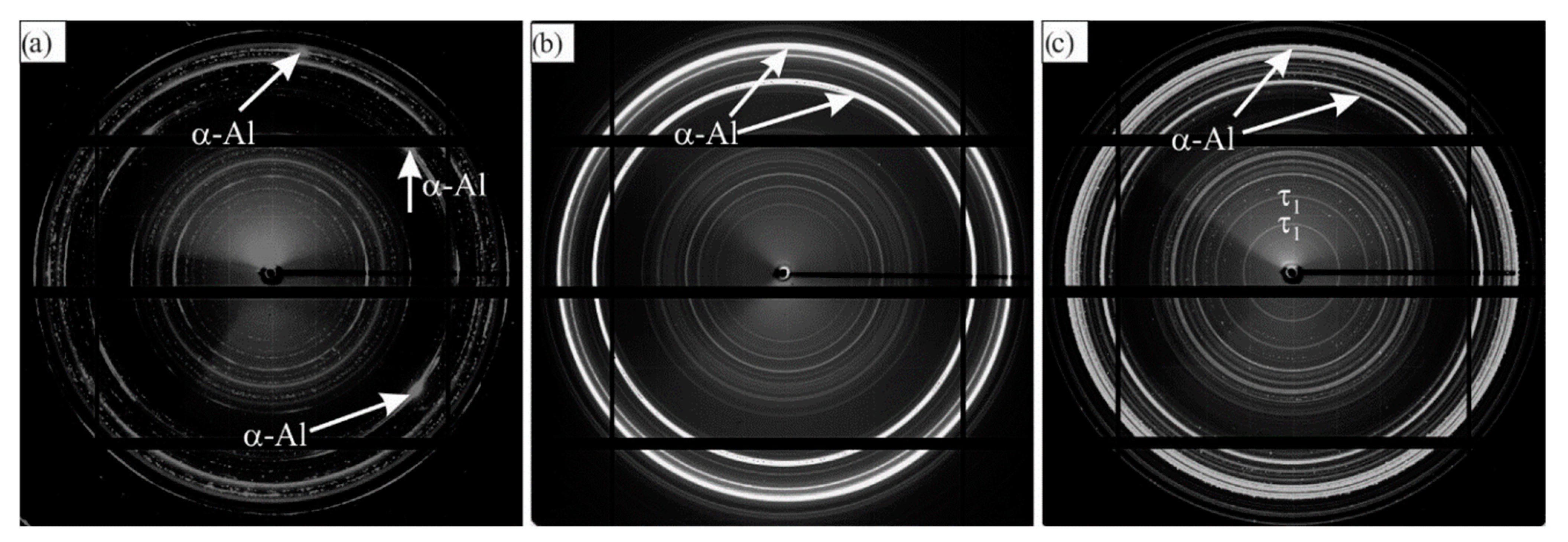
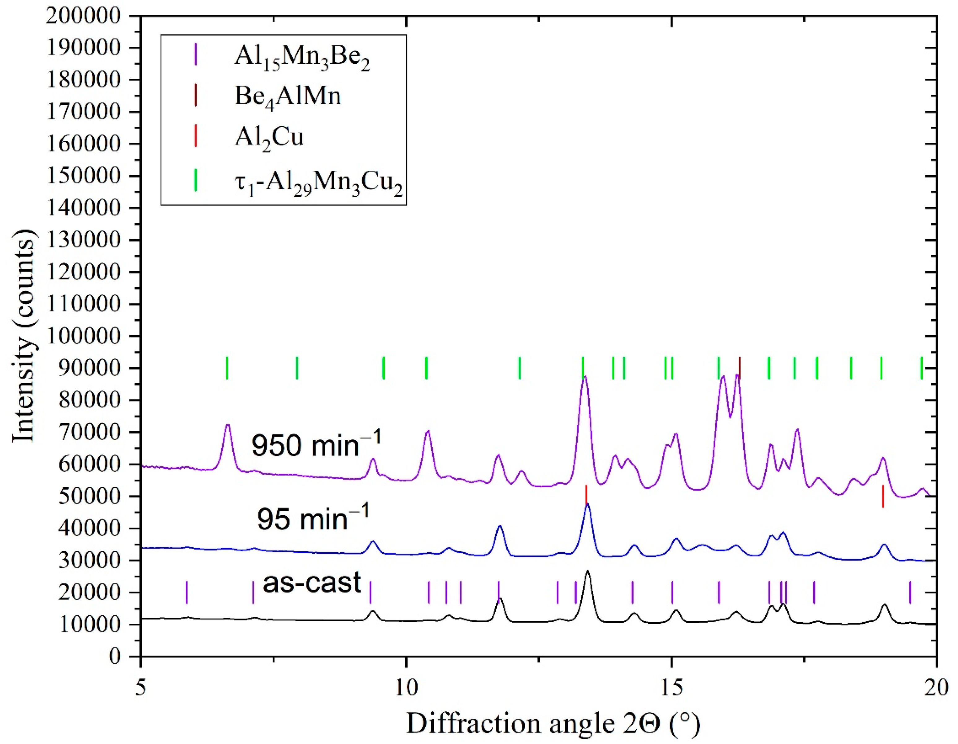
Figure 5 shows the variations in 2D diffraction images. In the as-cast state, large α-Al grain prevailed in the microstructure, and consequently, only a few diffraction spots could be seen in Figure 5a. Other diffraction rings, which were not continuous but consisted of discrete diffraction spots, mainly belonged to the Al15Mn3Be2 phase. The processing with 95 min−1 did not change the phase composition, but all rings became continuous. This observation can be explained by crushing larger Al15Mn3Be2 and other particles into a very fine dispersion, which is consistent with the microstructural observations. On the other hand, the size of the large α-Al crystal grains strongly decreased and could not even be observed in the light and scanning electron micrographs. The processing with 950 min−1 induced phase transformation of the Al15Mn3Be2 phase into the τ1-Al29Mn6Cu4 phase. Namely, the positions of inner rings in Figure 5c were at different positions than in Figure 4a,b. These changes can be nicely seen in the XRD diffraction spectra (Figure 6).
3.2. Characterisation of the Stir Zone
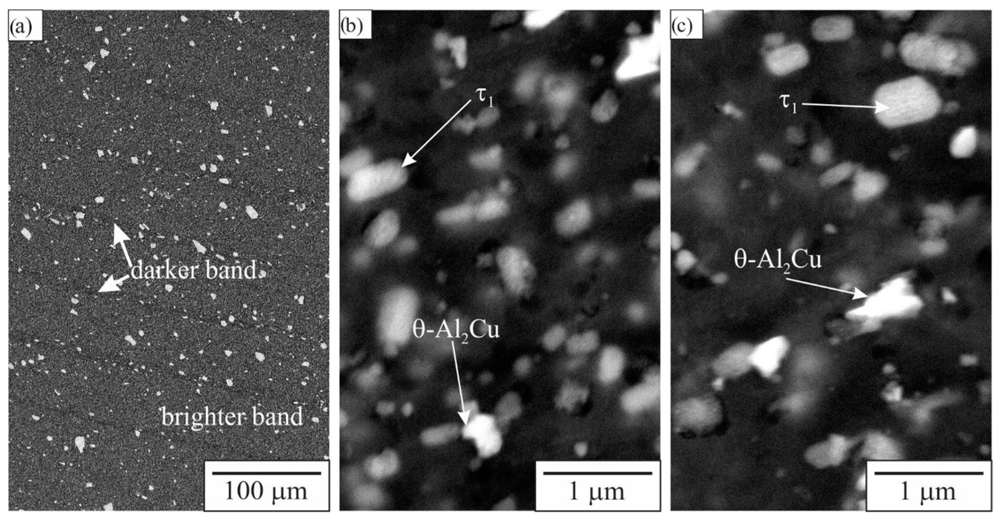
In the stir zone, the onion structure was observed to consist of wider, brighter, and thinner darker bands. HR-SEM images (Figure 7) showed that the volume fractions of particles was higher in the brighter bands, while their sizes were smaller. The brighter particles belonged to Al2Cu phase, while the others contained Al, Mn, and Cu, and were probably the τ1-phase, which the XRD identified. The indentation hardness and reduced modulus were slightly higher in the brighter bands (brighter bands: hardness 1.32 ± 0.17 GPa, Er = 85.09 ± 4.39 GPa; darker bands: hardness 1.29 ± 0.12 GPa, Er = 82.54 ± 4.61 GPa).
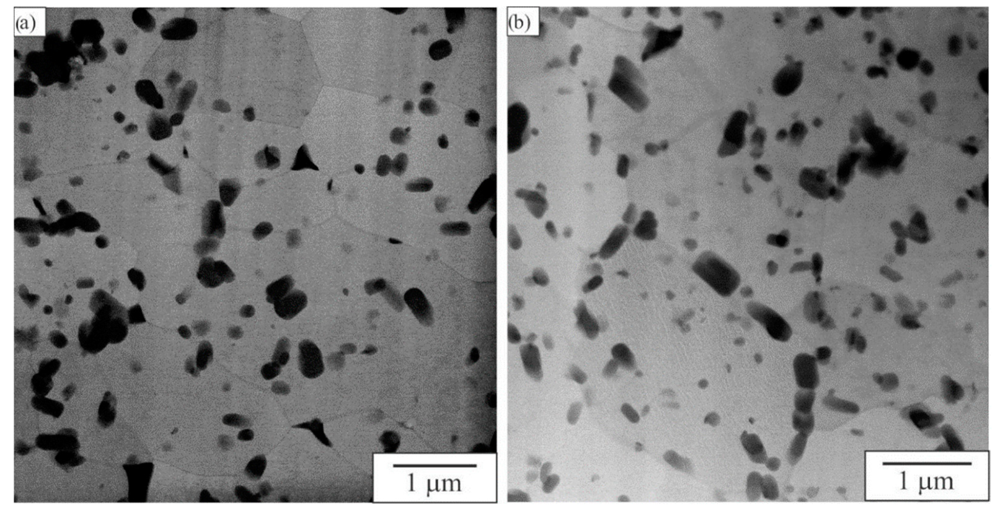
Greater microstructural changes occurred at higher energy input. A detailed TEM study of two samples in FSP 950 was conducted in the stir region; one was taken in the nugget zone and the other at the retreating side. Figure 8 shows the bright-field STEM micrographs. The microstructure consists of equiaxed crystal grains between 0.5 to 3 μm. The particles were dispersed both in the grain interiors and at the grain boundaries. This indicates that particles at the grain boundaries prevented grain growth during dynamic recrystallisation.
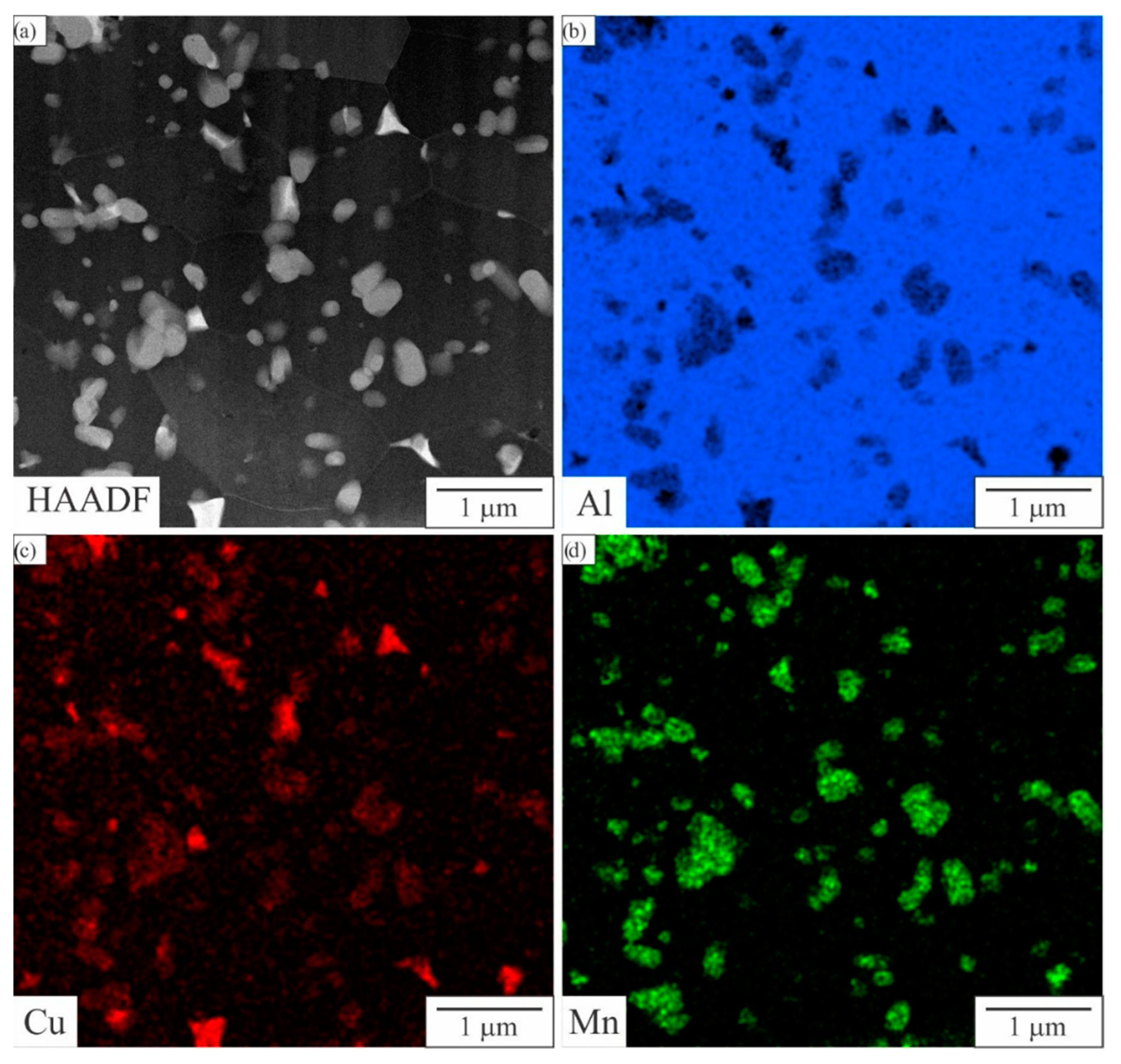
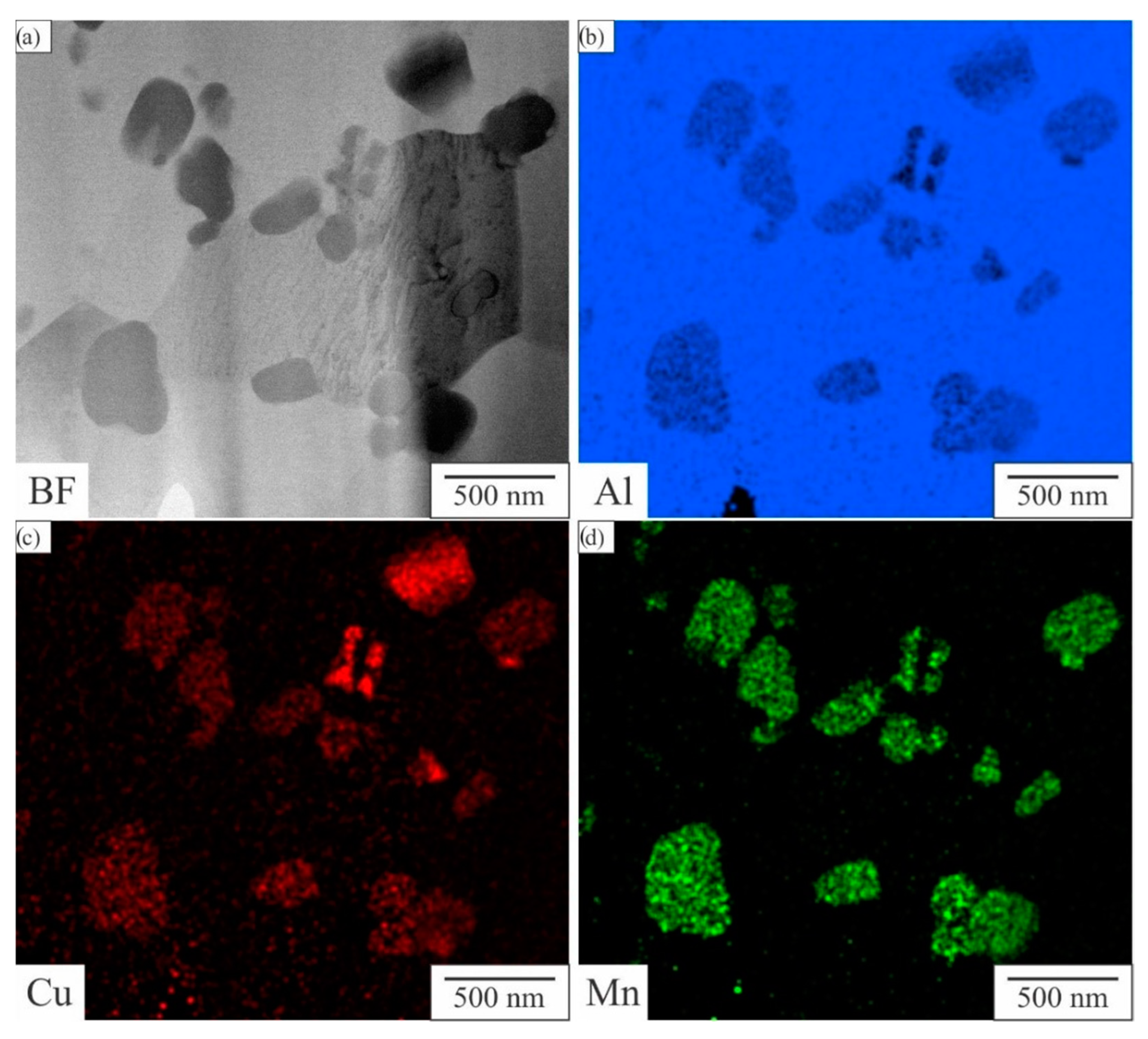
Figure 9 shows the HAADF STEM image and the corresponding distribution of Al, Cu, and Mn. Two types of particles prevailed. The red colour denotes Cu-rich particles, which are Al2Cu. They do not contain any other elements (Figure 10). On the other hand, the green particles contain both Mn and Cu, with a typical atomic ratio of Mn:Cu = 3:2 (Figure 10), which can be consistent with τ1-Al29Mn6Cu4. In the microstructure, we did not observe IQC and Be4AlMn.
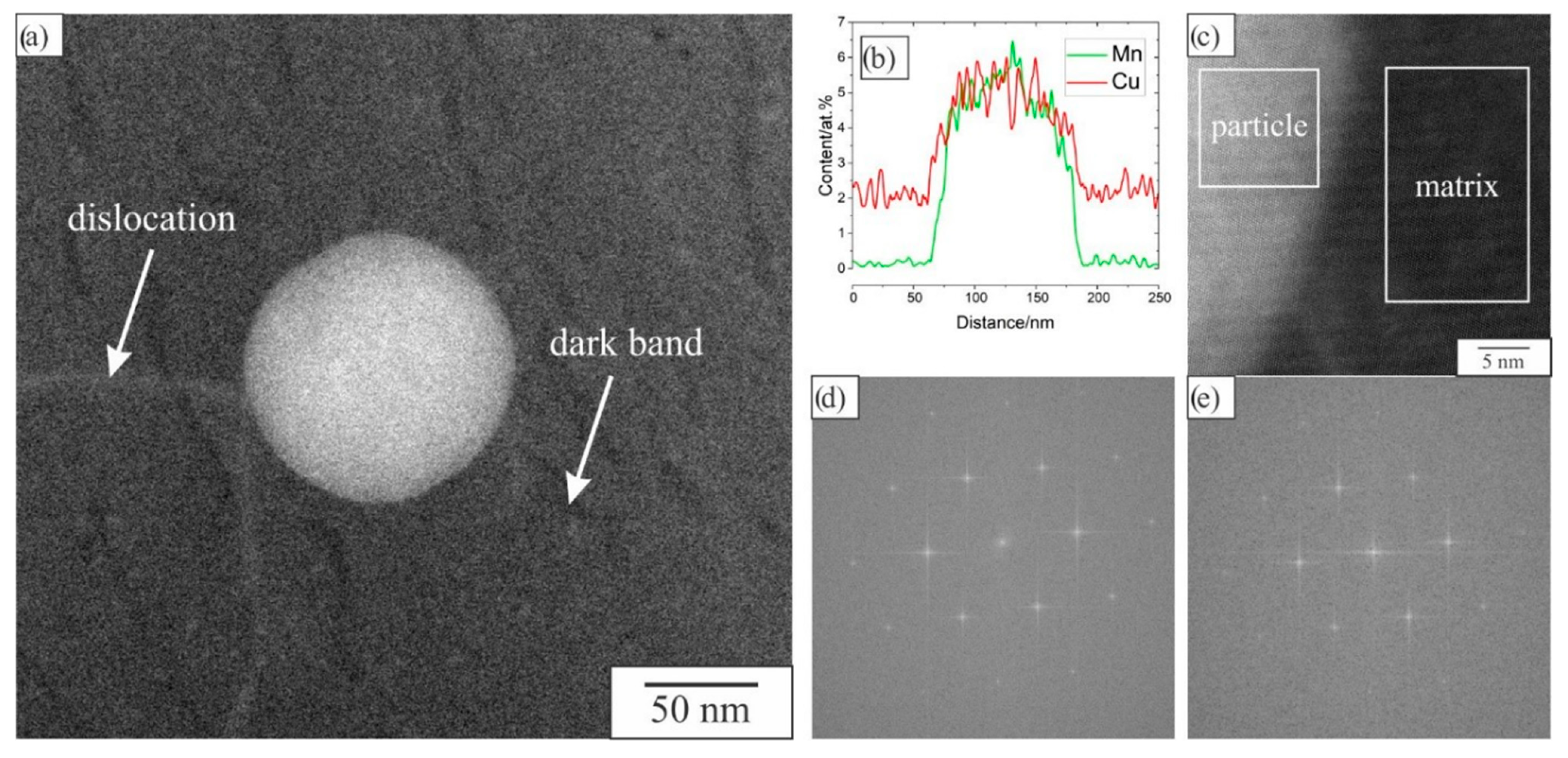
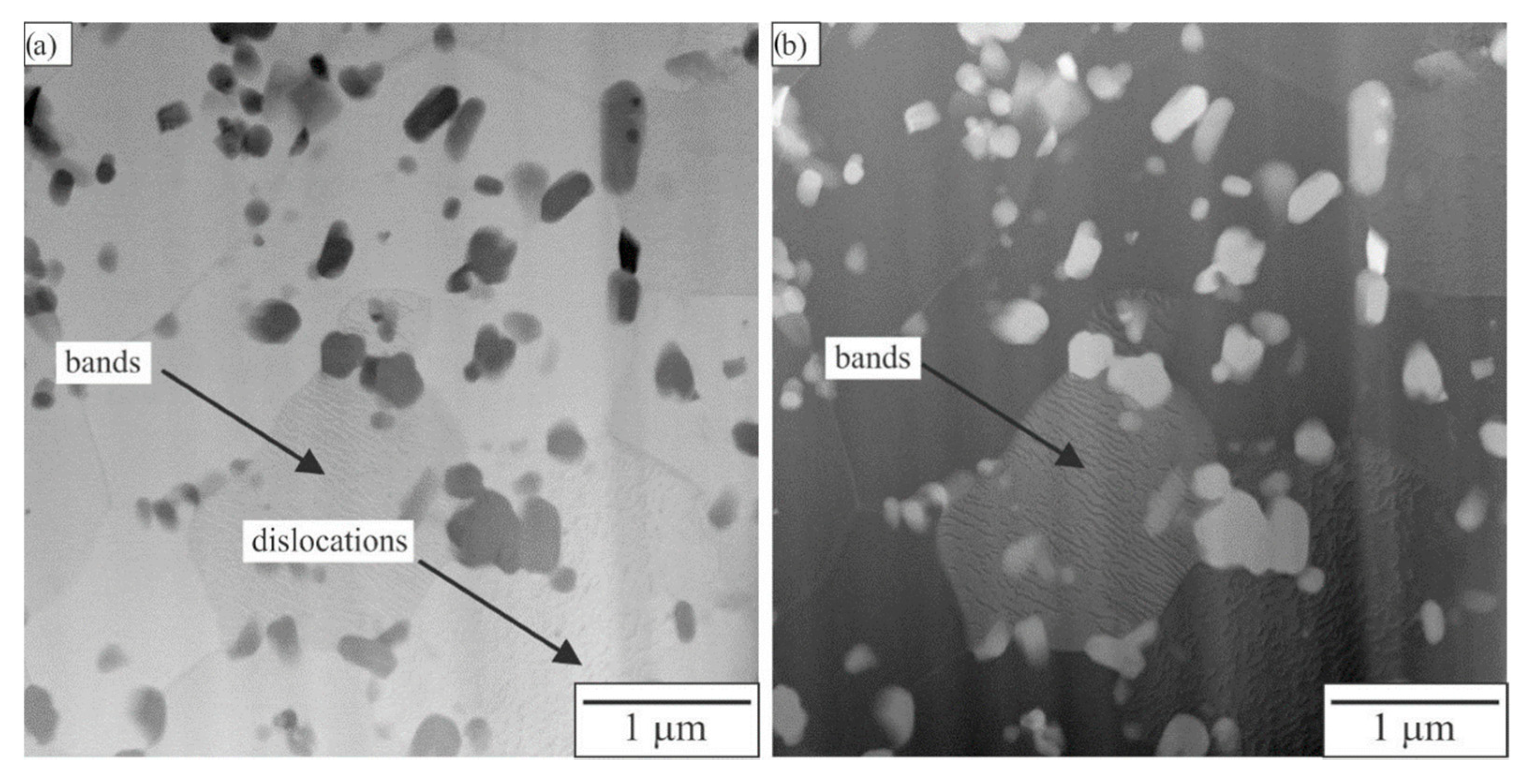
Figure 11 shows a detailed analysis of a spherical particle with a diameter of approximately 150 nm, which was positioned inside an αAl grain. It is very likely that this particle precipitated during FSP. The particle contains both Mn and Cu, so it can be identified as τ1. The particle did not show any specific orientation with α-Al. The particle may have formed before recrystallisation, therefore, no specific orientation relationship can be expected with the Al-matrix. In the matrix, individual dislocations were present. In addition, darker bands can be observed in the matrix in the HAAD-micrograph. It can be inferred that a higher content of Be was present in these bands. However, EDS was not able to detect Be.
3.3. Characterisation of the TMAZ
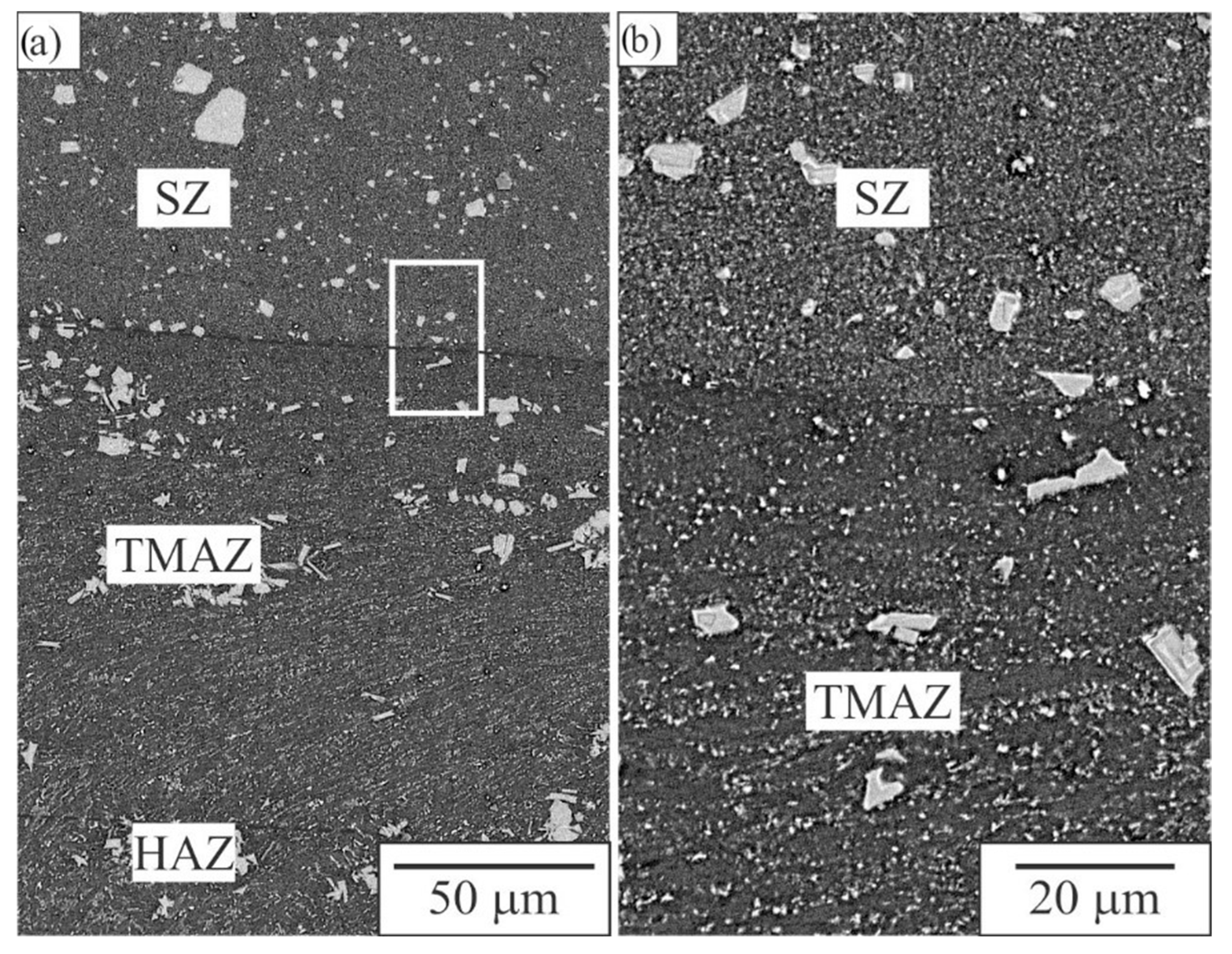
Figure 12 shows the transition from SZ to HAZ just below the nugget zone (below the pin) where the border between SZ and TMAZ was sharp. In the TMAZ, the particles were distributed in lines, showing the direction of plastic deformation. The smaller particles were broken coral-like IQC and Al2Cu. Some cracks were occasionally observed in larger Al15Mn3Be2 particles. The thickness of the TMAZ was around 150 μm. The distribution of phases in the HAZ was, at that magnification, the same as before processing.
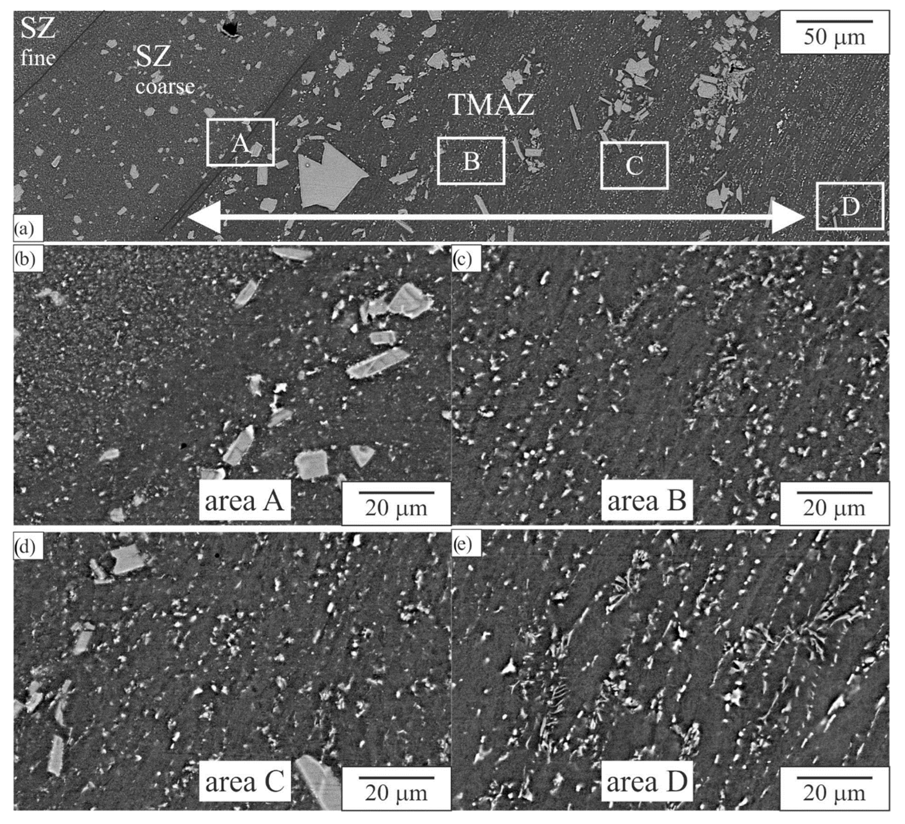
On the advancing side, a coarse band in the stir zone was observed; its thickness was between 100 μm and 150 μm (Figure 13a). The thickness of the TMAZ layer was about 350 μm, which was more than below the NZ. A TEM sample was taken approximately 50 μm from the SZ–TMAZ interface (Figure 14). The results showed that in this region, recrystallisation also took place. In this zone, Al2Cu and τ1 were also identified (Figure 15). In the grain indicated in Figure 14b, darker lines indicate the enrichment with Be.
Plastic flow also caused the fracture of some previous particles, which were much coarser than in the SZ. Spherical particles were much rarer than in the SZ. The particle contained Mn and Cu, and no mutual orientation relationship with the matrix was observed.
3.4. Characterisation of the HAZ
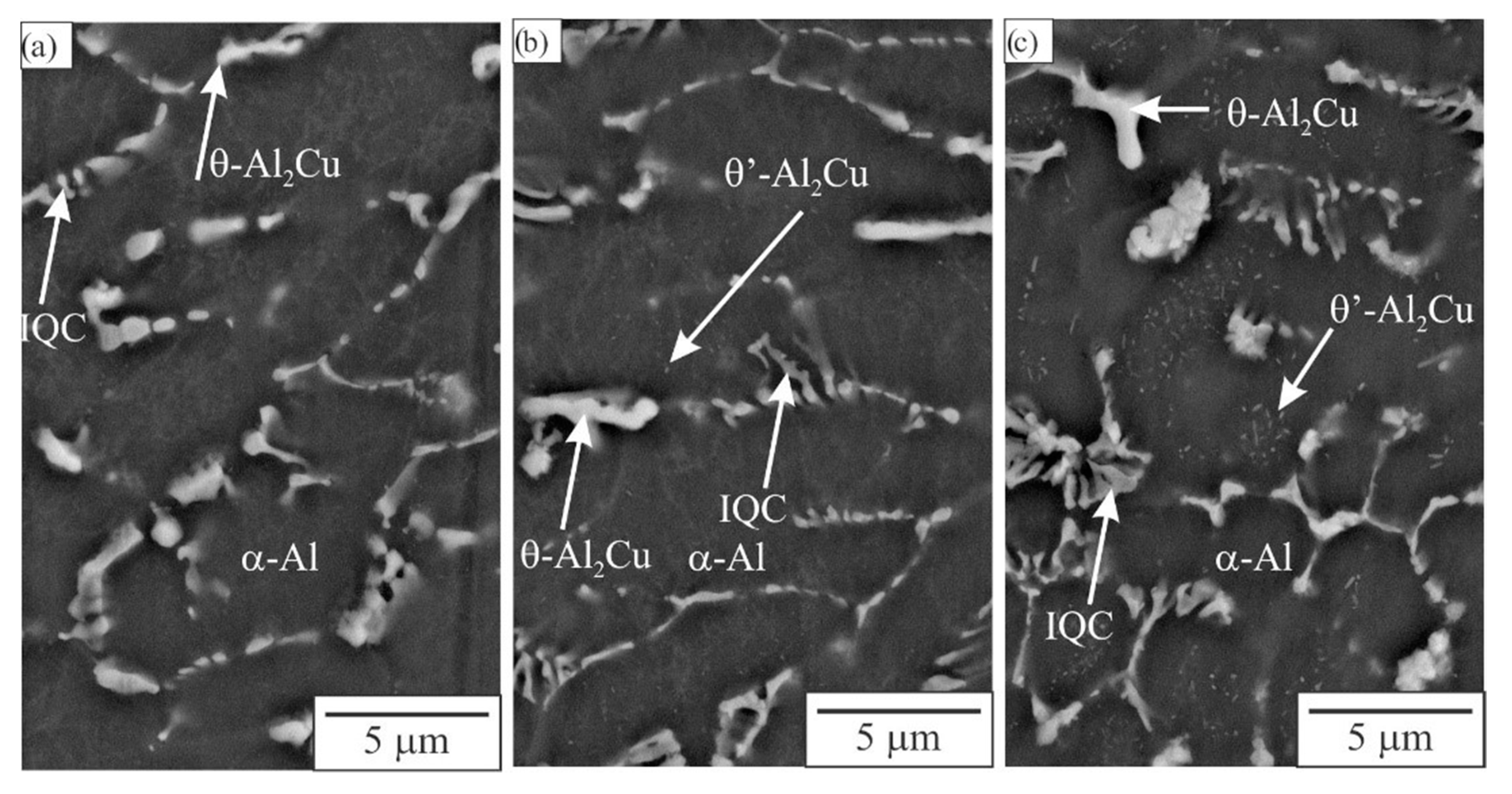
No plastic deformation occurred in the HAZ. The distribution of phases at the microlevel did not change. However, it was observed that during exposure to heat, the Al2Cu-based precipitates dissolved (Figure 16), which were almost completely dissolved about 3 mm from the TMAZ. Thus, the drop of indentation hardness in HAZ, close to the TMAZ, can be explained by the dissolution of θ’-Al2Cu precipitates present in the as-cast state.
3.5. Indentation Testing
Table 3 presents the indentation hardness using small loads. Typical indentation depths were 550–650 nm, thus the size of the indents was 4–5 μm. Through measurements, we avoided large particles, so the values corresponded to the properties in the microrange. No significant differences were observed despite dissimilar microstructures in different areas. The reduced modulus Er was around 80 GPa, which was larger than in pure aluminium (68 GPa) because of the presence of other phases. The Berkovich indentation hardness was in the range 1.1–1.3 GPa.
3.6. Microstructure Evolution during FSP
FSP zones are characterised by extremely high strain, strain rate, and temperature as well as the gradients of these parameters. Generally, they decrease from the nugget zones to the base alloy. The resulting variations in microstructure depend on the processing parameters, alloy composition, and initial microstructure. In this part, we will try to explain the observed results of the investigated quasicrystal-forming aluminium alloy. FSP causes high strains, thus strengthening the alloy by work hardening. However, very high temperatures can induce several processes that can soften the alloy. The processes are rather complex in single-phase alloys, but the current alloy is multicomponent and multiphase. Thus, additional explanations are required to understand the final microstructure.
The lowest rotation speed did not change the microstructure considerably, especially on the retreating side (Figure 2). Nevertheless, it increased the alloy hardness by about 30%. Deformation increased the dislocation density, but the temperature was lower and the softening was smaller than strengthening due to the lower energy input. On the other hand, the highest rotation speed caused a very uniform microstructure in the whole stir zone. The strengthening and softening were almost the same, so the hardness remained at approximately the same level as in the base alloy. Some stronger variations of hardness occurred only at the interface between TMAZ and HAZ. For the FSP, this is not of great importance because with several parallel passes, the microstructure can be the same in larger regions. The hardness variation can be of more importance in FSW, where TMAZ and HAZ remain in the material after welding. Nevertheless, in this alloy, variations were not pronounced.
3.6.1. Effect of FSP on the Matrix Al-Grains
Through the main part of the cast strip, elongated grains prevailed, with sizes of 250 μm × 60 μm. These grains transformed to equiaxed grains (about 2–3 μm in diameter) in the SZ and TMAZ. The fragmented and precipitated particles strongly prevented grain growth during dynamic recovery and recrystallisation. The mechanism is probably similar to that observed in other aluminium alloys. The decrease in grain size can considerably contribute to strengthening through the Hall–Petch relationship [26]. The size of grains did not change in the HAZ.
3.6.2. Effect of FSP on the Hexagonal Quasicrystalline Approximant Al15Mn3Be2 Phase
The Al15Mn3Be2 phase was present predominantly as coarse particles (longest dimension from 5 µm to more than 100 µm) that formed in the liquid prior to the crystallisation of α-Al. The particles were present throughout the cross-section, especially at the strip centre (area C in Figure 2). Such particles can be detrimental to mechanical properties, especially ductility. This phase was stable in the Al–Mn–Be system [27,28,29], but with the addition of Cu, it became metastable and transformed to τ1-Al29Mn6Cu4 [30,31,32] (in some aluminium alloys, precipitates of this phase formed and are usually denoted as T-precipitates, with the formula Al20Mn3Cu2 [33]). They did change in the HAZ, but in the TMAZ, cracks were observed only in some particles. and were disintegrated into much smaller particles in the stir zone. The metastable Al15Mn3Cu2 can transform to τ1 by the diffusion of Cu into the particles and Be out of them, but it can also partly dissolve in the matrix, enriching it with Be and Cu. The diffusivity of Cu in Al was relatively high [34], probably also of Be. The temperature in the stir zone (around 600 °C) was high, but the time of exposure was short; thus, the diffusion distance is limited. We observed that the composition of larger particles (larger than 5 μm) did not change. Perhaps only a thin outer layer was enriched in Cu. On the other hand, the particles smaller than 1 μm possessed a lot of Cu, thus, they surely transformed to τ1.
3.6.3. Effect of FSP on the IQC
IQC was formed during the final stages of solidification in the intercellular or interdendritic regions. It was principally present as a coral-like phase in the binary (α-Al + IQC) eutectic, and branches was mainly of sub-micrometre size. IQC phase studied in other alloys contained about 2 at.% Cu and 10 at.% Be, slightly less than Al15Mn3Be2. Under strain, the branches fracture easily, which occurred in both the TMAZ and SZ. IQC is also a metastable phase and it also transforms to τ1 by the diffusion of Cu into particles and Be out of them. Since the branch thickness was very low, a complete transformation to τ1 is expected.
3.6.4. Effect of FSP on θ-Al2Cu and Be4Al(Mn,Cu)
The Al2Cu phase appeared brightest in all electron-backscattered micrographs due to the high atomic number of copper, while the Be4Al(Mn, Cu) phase was darkest because of the high atomic fraction of light beryllium atoms. Both phases were stable in this alloy. Mechanical action can crush them into smaller particles, while elevated temperatures can cause their partial dissolution in the matrix, thus, the contents of Be and Cu dissolved in the matrix increased.
3.6.5. Processes in the Matrix
Partial dissolution of phases in the stir zone can cause a temporarily increase in alloying contents in the matrix. The equilibrium solubility of Be in Al was 0.1 wt.% (0.29 at.%) [33]. It is likely that high strains cause even higher contents of Be, similar to what can occur in mechanical alloying. Be does not form any compound with Al, since the enthalpy of mixing is positive both in the liquid and solid-state. Thus, the supersaturation of Be in Al can lead to demixing in the solid-state, with a spinodal type reaction. The brighter and darker bands in the matrix can be a result of demixing. However, to prove it, we need to use methods that will reveal Be.
In the matrix, precipitation of phases can also take place. The process is similar to T5 temper. The possible precipitates found in previous studies are IQC, τ1 (or T-precipitates), and Al2Cu-type precipitates. We found spherical precipitates with diameters of 50–150 μm. During FSP, Al2Cu-type precipitates cannot form because the solvus temperature is lower than the temperature in the SZ. At temperatures above 400 °C, the formation of T-precipitates is more likely than IQC. However, the orthogonal T-precipitates found in Al-alloys are rodlike, with a much larger length along the b-axis. Since most of the precipitates were spherical, it is not likely that T-precipitates would be formed, but spherical IQC precipitates might be formed first and then transformed to Al–Mn–Cu precipitates.
As shown by EDS, the Al-matrix contained more than 2 at.% Cu, which was close to its maximum solubility in the Al [35]. Thus, upon cooling, and especially at room temperature, natural ageing can occur through the precipitation of GP-zones or θ’’-precipitates.
In the HAZ, only the dissolution of θ’-precipitates can dissolve in the matrix. The solvus temperature for these precipitates is about 400 °C [36]. Thus, at 3 mm from the TMAZ–HAZ interface, the temperature was at least 400 °C. Thus, the alloy was relatively stable through short time exposure to temperatures at least up to 400 °C.
4. Conclusions
The main effects of FSP processing of the twin-cast Al–Mn–Cu–Be alloy are:
- -
- Fragmentation and more uniform distribution of primary intermetallic phases;
- -
- Dispersion of the eutectic icosahedral phase;
- -
- Recrystallisation of the matrix grains in the stir zone and in the TMAZ;
- -
- Transformation of small initial IQC and small fragments of Al15Mn3Be2 phases to Al–Mn–Cu intermetallic phase τ1;
- -
- Precipitation of spherical precipitates containing Al, Mn, and Cu. Possible formation of IQC precipitates and their transformation to τ1;
- -
- Within the Al-matrix, darker bands were observed, probably the decomposition of the Al-matrix; some kind of a spinodal decomposition to Be-rich and Be-lean bands; and
- -
- Dissolution of θ’-Al2Cu precipitates in the TMAZ and HAZ, present in the as-cast state).
For FSP of a novel, multicomponent, and multiphase alloy, additional processes can take place in comparison to that found in conventional aluminium alloys. Thus, further fundamental studies are required to obtain a deeper insight into them.
Author Contributions
Conceptualisation, F.Z. and T.B.; Methodology, T.B.; Validation, F.Z. and T.B.; Formal analysis, F.Z.; Investigation, M.M., T.B., F.Z., A.K., L.H. and D.K.; Resources, T.B. and D.K.; Data curation, M.M. and L.H.; Writing—original draft preparation, M.M.; Writing—review and editing, F.Z.; Visualisation, M.M. and F.Z.; Supervision, T.B. and D.K.; Project administration, T.B.; Funding acquisition, F.Z. All authors have read and agreed to the published version of the manuscript.
Funding
This research was funded by the Slovenian Research Agency (research core funding Nos. P2-0120 and I0-0029). The XRD investigations were carried out at Elettra, Sincrotrone Trieste, Italy, in the framework of Proposal 20205071. The TEM investigations were obtained at the Ernst Ruska-Centre (ER-C) for Microscopy and Spectroscopy with Electrons at the Forschungszentrum Jülich (FZJ) in Germany (http://dx.doi.org/10.17815/jlsrf-2-106 (accessed on 25 March 2022) and http://dx.doi.org/10.17815/jlsrf-2-68 (accessed on 25 March 2022)). Partial financial support for this project from European Union’s Horizon 2020 Research and Innovation Programme (Grant No. 823717, project “ESTEEM3”).
Institutional Review Board Statement
Not applicable.
Informed Consent Statement
Not applicable.
Data Availability Statement
Not applicable.
Acknowledgments
We thank Luisa Barba for the support with the XRD experiments at Elettra. The authors acknowledge the use of the research equipment Nano Test Vantage indentation tester, procured within the project “Upgrading national research infrastructures—RIUM”, which was co-financed by the Republic of Slovenia, the Ministry of Education, Science and Sport and the European Union from the European Regional Development Fund.
Conflicts of Interest
The authors declare no conflict of interest.
References
- Brough, D.; Jouhara, H. The aluminium industry: A review on state-of-the-art technologies, environmental impacts and possibilities for waste heat recovery. Int. J. Thermofluids 2020, 1, 100007. [Google Scholar] [CrossRef]
- Wang, W.; Pan, Q.; Lin, G.; Yu, Y.; Wang, X.; Liu, Y.; Sun, Y.; Ye, J.; Huang, Z.; Xiang, S.; et al. Internal friction and heat resistance of Al, Al–Ce, Al–Ce–Zr and Al–Ce–(Sc)–(Y) aluminum alloys with high strength and high electrical conductivity. J. Mater. Res. Technol. 2021, 14, 1255. [Google Scholar] [CrossRef]
- Zupanič, F.; Bončina, T. Heat-Resistant Al-Alloys with Quasicrystalline and L12- Precipitates. Solid State Phenom. 2022, 327, 26. [Google Scholar] [CrossRef]
- Paidar, M.; Ali, K.S.A.; Mohanavel, V.; Mehrez, S.; Ravichandran, M.; Ojo, O.O. Weldability and mechanical properties of AA5083-H112 aluminum alloy and pure copper dissimilar friction spot extrusion welding-brazing. Vacuum 2021, 187, 10080. [Google Scholar] [CrossRef]
- Vimalraj, C.; Kah, P. Experimental Review on Friction Stir Welding of Aluminium Alloys with Nanoparticles. Metals 2021, 11, 390. [Google Scholar] [CrossRef]
- Verma, S.; Misra, J.P. Experimental investigation on friction stir welding of dissimilar aluminium alloys. Proc. Inst. Mech. Eng. Part E-J. Process Mech. Eng. 2021, 235, 1545. [Google Scholar] [CrossRef]
- Bončina, T.; Albu, M.; Zupanič, F. Ageing of Al-Mn-Cu-Be Alloys for Stimulating Precipitation of Icosahedral Quasicrystals. Metals 2020, 10, 937. [Google Scholar] [CrossRef]
- Haga, T. High Speed Roll Caster for Aluminum Alloy. Metals 2021, 11, 520. [Google Scholar] [CrossRef]
- Zupanič, F.; Macerl, M.; Haga, T.; Bončina, T. Microstructure and Indentation Properties of Single-Roll and Twin-Roll Casting of a Quasicrystal-Forming Al-Mn-Cu-Be Alloy. Metals 2022, 12, 187. [Google Scholar] [CrossRef]
- Heidarzadeh, A.; Mironov, S.; Kaibyshev, R.; Çam, G.; Simar, A.; Gerlich, A.; Khodabakhshi, F.; Mostafaei, A.; Field, D.P.; Robson, J.D.; et al. Friction stir welding/processing of metals and alloys: A comprehensive review on microstructural evolution. Prog. Mater. Sci. 2021, 117, 100752. [Google Scholar] [CrossRef]
- Kumar, A.; Kumar, V. A review of recent progress in the fabrication of surface composites through friction stir processing. Mater. Today Proc. 2022, in press. [Google Scholar] [CrossRef]
- Puviyarasan, M.; Pushkaran, S.; Senthil, T.S.; Raja Karthikeyan, K. Effect of process parameters on material strength (AA6061-T6) during Friction Stir Processing: Simulation and Experimental validation. Mater. Toda Proc. 2022. [Google Scholar] [CrossRef]
- Agrawal, A.K.; Narayanan, R.G.; Kailas, S.V. Formability and Instability Evaluation of Friction Stir Processed AA6063-T6 Tubes During End Forming and Numerical Prediction. J. Mater. Eng. Perform. 2021, 30, 973. [Google Scholar] [CrossRef]
- Yadav, J.; Choudhary, P.; Yadav, N.; Kumar Singh, P.; Gupta, N.; Bansal, K.; Gangil, N.; Noor Siddiquee, A. Microstructural investigation on friction stir welded AA6063 pipe. Mater. Today Proc. 2022. [Google Scholar] [CrossRef]
- Tao, Y.; Zhang, Z.; Xue, P.; Ni, D.R.; Xiao, B.L.; Ma, Z.Y. Effect of post weld artificial aging and water cooling on microstructure and mechanical properties of friction stir welded 2198-T8 Al-Li joints. J. Mater. Sci. Technol. 2022, 123, 92. [Google Scholar] [CrossRef]
- Hassanifard, S.; Ghiasvand, A.; Hashemi, S.M.; Varvani-Farahani, A. The effect of the friction stir welding tool shape on tensile properties of welded Al 6061-T6 joints. Mater. Today Commun. 2022, 31, 103457. [Google Scholar] [CrossRef]
- Xu, X.; Zhang, C.; Derazkola, H.A.; Demiral, M.; Zain, A.M.; Khan, A. UFSW tool pin profile effects on properties of aluminium-steel joint. Vacuum 2021, 192, 10460. [Google Scholar] [CrossRef]
- Janeczek, A.; Tomkow, J.; Fydrych, D. The Influence of Tool Shape and Process Parameters on the Mechanical Properties of AW-3004 Aluminium Alloy Friction Stir Welded Joints. Materials 2021, 14, 3244. [Google Scholar] [CrossRef]
- Ekinci, O.; Balalan, Z. Effect of tool pin geometry on microstructure and mechanical properties of friction stir spot welds of 7075-T651 aluminium alloy. Metall. Res. Technol. 2021, 118, 110. [Google Scholar] [CrossRef]
- Balamurugan, M.; Gopi, S.; Mohan, D.G. Influence of tool pin profiles on the filler added friction stir spot welded dissimilar aluminium alloy joints. Mater. Res. Express 2021, 8, 96531. [Google Scholar] [CrossRef]
- Tunde Azeez, S.; Madindwa Mashinini, P. Mathematical modeling of friction stir welding and processing—A short review. Mater. Today Proc. 2022. [Google Scholar] [CrossRef]
- Jia, H.; Wu, K.; Sun, Y. Numerical and experimental study on the thermal process, material flow and welding defects during high-speed friction stir welding. Mater. Today Commun. 2022, 31, 103526. [Google Scholar] [CrossRef]
- Narhari Tekale, S.; Dolas, D.R. Study of fabrication methods and various reinforcements with aluminium for automotive application—A review. Mater. Today Proc. 2022. [Google Scholar] [CrossRef]
- Cao, X.; Shi, Q.; Liu, D.; Feng, Z.; Liu, Q.; Chen, G. Fabrication of in situ carbon fiber/aluminum composites via friction stir processing: Evaluation of microstructural, mechanical and tribological behaviors. Compos. Part B Eng. 2018, 139, 97. [Google Scholar] [CrossRef]
- Mozammil, S.; Koshta, E.; Jha, P.K. Abrasive Wear Investigation and Parametric Process Optimization of in situ Al-4.5%Cu-xTiB(2) Composites. Trans. Indian Inst. Met. 2021, 74, 629. [Google Scholar] [CrossRef]
- Figueiredo, R.B.; Langdon, T.G. Deformation mechanisms in ultrafine-grained metals with an emphasis on the Hall–Petch relationship and strain rate sensitivity. J. Mater. Res. Technol. 2021, 14, 137. [Google Scholar] [CrossRef]
- Mondolfo, L.F. Aluminum-Beryllium-Manganese System; Butterworths: London, UK, 1976; p. 447. [Google Scholar]
- Stiltz, S. Aluminum—Beryllium—Manganese. In Ternary Alloys: A Comprehensive Compendium of Evaluated Constitutional Data and Phase Diagrams; Petzow, G., Effenberg, G., Eds.; VCH Verlagsgesellschaft mbH: Weinheim, Germany; Basel, Switzerland; Cambridge, UK; New York, NY, USA, 1990; Volume 3, p. 361. [Google Scholar]
- Kim, S.H.; Song, G.S.; Fleury, E.; Chattopadhyay, K.; Kim, W.T.; Kim, D.H. Icosahedral quasicrystalline and hexagonal approximant phases in the Al-Mn-Be alloy system. Philos. Mag. A-Phys. Condens. Matter Struct. Defect Mech. Prop. 2002, 82, 1495. [Google Scholar] [CrossRef]
- Rozman, N.; Medved, J.; Zupanic, F. Microstructural evolution in Al-Mn-Cu-(Be) alloys. Philos. Mag. 2011, 91, 4230. [Google Scholar] [CrossRef] [Green Version]
- Lukas, H.L. Al-Cu-Mn (Aluminium—Copper—Manganese). In Landolt-Börnstein—Group IV Physical Chemistry, Numerical Data and Functional Relationships in Science and Technology; Effenberg, G., Ilyenko, S., Eds.; Springer Materials—The Landolt-Börnstein Database: Berlin/Heidelberg, Germany, 2004; Available online: http://www.springermaterials.com (accessed on 25 March 2022).
- Lukas, H.L. Aluminum—Copper—Manganese. In Ternary Alloys: A Comprehensive Compendium of Evaluated Constitutional Data and Phase Diagrams; Petzow, G., Effenberg, G., Eds.; VCH Verlagsgesellschaft mbH: Weinheim, Germany; Basel, Switzerland; Cambridge, UK; New York, NY, USA, 1990; Volume 4, p. 567. [Google Scholar]
- Shen, Z.; Liu, C.; Ding, Q.; Wang, S.; Wei, X.; Chen, L.; Li, J.; Zhang, Z. The structure determination of Al20Cu2Mn3 by near atomic resolution chemical mapping. J. Alloys Compd. 2014, 601, 25. [Google Scholar] [CrossRef]
- Du, Y.; Chang, Y.A.; Huang, B.Y.; Gong, W.P.; Jin, Z.P.; Xu, H.H.; Yuan, Z.H.; Liu, Y.; He, Y.H.; Xie, F.Y. Diffusion coefficients of some solutes in fcc and liquid Al: Critical evaluation and correlation. Mater. Sci. Eng. A-Struct. Mater. Prop. Microstruct. Process. 2003, 363, 140. [Google Scholar] [CrossRef]
- Predel, B. Al-Cu (Aluminum-Copper): Datasheet from Landolt-Börnstein—Group IV Physical Chemistry · Volume 5A: “Ac-Au–Au-Zr” in SpringerMaterials; Springer: Berlin/Heidelberg, Germany, 2004. [Google Scholar] [CrossRef]
- Zhao, J.-C. High-Throughput and Systematic Study of Phase Transformations and Metastability Using Dual-Anneal Diffusion Multiples. Metall. Mater. Trans. A 2020, 51, 5006. [Google Scholar] [CrossRef]
Figure 1.
Friction stir processing: (a) schematic drawing of FSP, (b) drawing of the applied pin, and (c) the equipment used for FSP.
Figure 1.
Friction stir processing: (a) schematic drawing of FSP, (b) drawing of the applied pin, and (c) the equipment used for FSP.

Figure 2.
Cross-sections of the processed regions. (a) Schematic presentation of different areas. The composed light micrograph of the Al–Mn–Cu–Be alloy after FSP with (b) FSP95 and (c) FSP950. (E—edge, M—middle, C—centre, NZ—nugget zone, T-RS—transition retreating side, T-AS—transition advancing side, T-NZ—transition nugget zone).

Figure 3.
The backscattered electron micrographs of (a–c) the twin-roll cast strip; (d–f) sample FSP95, and (g–i) sample FSP950.
Figure 3.
The backscattered electron micrographs of (a–c) the twin-roll cast strip; (d–f) sample FSP95, and (g–i) sample FSP950.

Figure 4.
Variation of Vickers indentation hardness 700 μm below the surface for rotational speeds of (a) sample FSP95 and (b) sample FSP950.
Figure 4.
Variation of Vickers indentation hardness 700 μm below the surface for rotational speeds of (a) sample FSP95 and (b) sample FSP950.

Figure 5.
2D-XRD images. (a) As-cast, (b) sample FSP95 in the stir zone, and (c) sample FSP950 in the stir zone (taken close to the area NZ in Figure 2).
Figure 5.
2D-XRD images. (a) As-cast, (b) sample FSP95 in the stir zone, and (c) sample FSP950 in the stir zone (taken close to the area NZ in Figure 2).

Figure 6.
X-ray spectra of the investigated alloy in the as-cast condition and after friction stir processing (taken close to area A in Figure 2).
Figure 6.
X-ray spectra of the investigated alloy in the as-cast condition and after friction stir processing (taken close to area A in Figure 2).

Figure 7.
Microstructure in the stir zone (BSE) of sample FSP950, area A in Figure 2: (a) onion structure, consisting of wider brighter and thinner darker bands, (b) distribution of particles in a brighter band, (c) distribution of particles in a darker band.
Figure 7.
Microstructure in the stir zone (BSE) of sample FSP950, area A in Figure 2: (a) onion structure, consisting of wider brighter and thinner darker bands, (b) distribution of particles in a brighter band, (c) distribution of particles in a darker band.

Figure 8.
Bright-field transmission electron micrographs of sample FSP950. (a) stir zone, region NZ in Figure 2, (b) within the stir zone in region T-AS.
Figure 8.
Bright-field transmission electron micrographs of sample FSP950. (a) stir zone, region NZ in Figure 2, (b) within the stir zone in region T-AS.

Figure 9.
Microstructure and elemental mapping of sample FSP950 in the NZ. (a) HAADF STEM micrograph, (b) distribution of Al, (c) distribution of Cu, and (d) distribution of Mn extracted from EDS.
Figure 9.
Microstructure and elemental mapping of sample FSP950 in the NZ. (a) HAADF STEM micrograph, (b) distribution of Al, (c) distribution of Cu, and (d) distribution of Mn extracted from EDS.

Figure 10.
EDS analysis of two particles in the NZ in areas #1 and #2. Inset is the elemental maps of Cu and Mn.
Figure 10.
EDS analysis of two particles in the NZ in areas #1 and #2. Inset is the elemental maps of Cu and Mn.

Figure 11.
A spherical precipitate of sample FSP950 in the NZ. (a) The HAADF STEM micrograph, (b) EDS linescans for Cu and Mn, (c) High-resolution STEM image at the interface between the matrix and particle, (d) FFT of the matrix ([110] zone axis), and (e) FFT of the particle (only matrix diffraction spots can be seen).

Figure 12.
TMAZ below the pin of sample FSP950 (area T-NZ in Figure 2). (a) Transition from SZ to HAZ, (b) enlarged image of the interface between SZ and TMAZ.
Figure 12.
TMAZ below the pin of sample FSP950 (area T-NZ in Figure 2). (a) Transition from SZ to HAZ, (b) enlarged image of the interface between SZ and TMAZ.

Figure 13.
Transition from SZ to HAZ of the advancing side of sample FSP950 (within the area T-AS in Figure 2). (a) Composed image of the transition. (b–e) Enlarged images of the areas indicated in (a).
Figure 13.
Transition from SZ to HAZ of the advancing side of sample FSP950 (within the area T-AS in Figure 2). (a) Composed image of the transition. (b–e) Enlarged images of the areas indicated in (a).

Figure 14.
Microstructure in the TMAZ of sample FSP950. (a) Bright-field and (b) HAADF STEM micrographs.
Figure 14.
Microstructure in the TMAZ of sample FSP950. (a) Bright-field and (b) HAADF STEM micrographs.

Figure 15.
Microstructure in the TMAZ, close to the stir zone (within the area TR-S in Figure 2) of sample FSP950. (a) Bright-field STEM micrograph (a) and elemental distributions of (b) Al, (c) Cu, and (d) Mn extracted from EDS.
Figure 15.
Microstructure in the TMAZ, close to the stir zone (within the area TR-S in Figure 2) of sample FSP950. (a) Bright-field STEM micrograph (a) and elemental distributions of (b) Al, (c) Cu, and (d) Mn extracted from EDS.

Figure 16.
Microstructures in the heat affected zone (HAZ) at different distances from the stir zone at the advancing side of sample FSP950: (a) 2 mm, (b) 3 mm, and (c) 4 mm.
Figure 16.
Microstructures in the heat affected zone (HAZ) at different distances from the stir zone at the advancing side of sample FSP950: (a) 2 mm, (b) 3 mm, and (c) 4 mm.


Table 1.
The chemical composition of the investigated alloy as determined using AES-ICP (atomic emission spectroscopy–inductively coupled plasma).
Table 1.
The chemical composition of the investigated alloy as determined using AES-ICP (atomic emission spectroscopy–inductively coupled plasma).
| Element | Wt.% | At.% |
|---|---|---|
| Mn | 4.21 | 2.14 |
| Cu | 4.26 | 1.87 |
| Be | 0.696 | 2.15 |
| Si | 0.02 | 0.02 |
| Fe | 0.03 | 0.02 |
| Al | balance | balance |
Table 2.
Friction stir processing parameters.
| Parameter | Value |
|---|---|
| tilt angle, α | 1.5° |
| traverse speed, v | 46 mm/min |
| rotation speed, n | 95 min−1, 950 min−1 |
| pin length | 2.7 mm |
| shoulder diameter | 17 mm |
Table 3.
Berkovich indentation hardness at specific positions. The average values and standard deviations for 25 measurements, the maximum load was 10 mN.
Table 3.
Berkovich indentation hardness at specific positions. The average values and standard deviations for 25 measurements, the maximum load was 10 mN.
| FSP 95 | FSP 950 | |||
|---|---|---|---|---|
| Position | Berkovich Indentation Hardness/GPa | Reduced Indentation Modulus/GPa | Berkovich Indentation Hardness/GPa | Reduced Indentation Modulus/GPa |
| HAZ-AS | 1.23 ± 0.06 | 75.27 ± 2.31 | 1.22 ± 0.07 | 80.43 ± 1.91 |
| HAZ-RS | 1.18 ± 0.07 | 81.69 ± 3.22 | 1.24 ± 0.05 | 78.56 ± 2.15 |
| TMAZ-AS | 1.19 ± 0.07 | 74.58 ± 2.39 | 1.14 ± 0.08 | 81.73 ± 2.61 |
| TMAZ-RS | 1.14 ± 0.07 | 79.26 ± 2.17 | 1.25 ± 0.19 | 84.23 ± 4.31 |
| SZ-NZ | 1.25 ± 0.05 | 80.09 ± 1.87 | 1.31 ± 0.15 | 85.09 ± 4.50 |
| SZ-coarse | - | - | 1.21 ± 0.12 | 82.08 ± 3.48 |
| SZ-fine | 1.19 ± 0.11 | 79.55 ± 2.98 | 1.21 ± 0.18 | 83.04 ± 6.34 |
Publisher’s Note: MDPI stays neutral with regard to jurisdictional claims in published maps and institutional affiliations. |
© 2022 by the authors. Licensee MDPI, Basel, Switzerland. This article is an open access article distributed under the terms and conditions of the Creative Commons Attribution (CC BY) license (https://creativecommons.org/licenses/by/4.0/).
Share and Cite
MDPI and ACS Style
Macerl, M.; Zupanič, F.; Hočuršćak, L.; Klobčar, D.; Kovács, A.; Bončina, T. Microstructure and Properties after Friction Stir Processing of Twin-Roll Cast Al–Mn–Cu–Be Alloy. Crystals 2022, 12, 630. https://doi.org/10.3390/cryst12050630
AMA Style
Macerl M, Zupanič F, Hočuršćak L, Klobčar D, Kovács A, Bončina T. Microstructure and Properties after Friction Stir Processing of Twin-Roll Cast Al–Mn–Cu–Be Alloy. Crystals. 2022; 12(5):630. https://doi.org/10.3390/cryst12050630
Chicago/Turabian StyleMacerl, Matjaž, Franc Zupanič, Lara Hočuršćak, Damjan Klobčar, András Kovács, and Tonica Bončina. 2022. "Microstructure and Properties after Friction Stir Processing of Twin-Roll Cast Al–Mn–Cu–Be Alloy" Crystals 12, no. 5: 630. https://doi.org/10.3390/cryst12050630
Note that from the first issue of 2016, this journal uses article numbers instead of page numbers. See further details here.