
About One Approach to Using Dynamic Models to Build Digital Twins
by
 , , ,
, , ,
Alexander Ivanovich Vodyaho
1,* ,
,
Nataly Alexandrovna Zhukova
1,2,
Yulia Alexandrovna Shichkina
1,
Fahem Anaam
1 and
Saddam Abbas
1 1
Faculty of Computer Science and Technology, Saint Petersburg Electrotechnical University “LETI”, 197376 St. Petersburg, Russia
2
St. Petersburg Federal Research Centre of the Russian Academy of Sciences (SPCRAS), 199178 St. Petersburg, Russia
*
Author to whom correspondence should be addressed.
Designs 2022, 6(2), 25; https://doi.org/10.3390/designs6020025
Submission received: 1 February 2022
/
Revised: 21 February 2022
/
Accepted: 25 February 2022
/
Published: 1 March 2022
Abstract
:The modern stage of technology development is characterized by the emergence of new paradigms for the construction of anthropogenic systems, such as cyber-physical systems, socio-cybernetic systems, etc. The task of data acquisition about the state of a multi-level system and managing the structure and behavior of a system consisting of many thousands of elements of different physical nature is a complex task. This article describes one of possible approaches to solving the problem of data acquisition and management of the structure of a large-scale heterogeneous system. The proposed approach is based on the idea of using dynamic digital twins, which are dynamic models of the observed system. This approach was used for the development of systems in various subject domains, in particular, in production management systems built on the Industry 4.0 principle, in the development of a technical support system for cable television networks and in the development of support systems for the construction of educational trajectories.
1. Introduction
A distinctive feature of the current stage of the development of modern technologies is the new level of complexity and intelligence of the created anthropogenic systems, the specific features of which are large size, complex behavior, as well as variability of structure and behavior. A significant part of the modern anthropogenic systems can be positioned as intelligent systems [1,2]. The mechanisms of working with knowledge are increasingly used in the development of modern information systems to realize “smart” functions [3].
Almost all large-scale systems have the property of variability of structure and/or behavior, such systems, with a few exceptions, are distributed systems. At the same time, many of them are built on the basis of such paradigms and platforms as Ambient Intelligence (AmI) [2], Internet of Things (IoT) [3,4], Industrial Internet of Things (IIoT) [5,6,7], Cloud [8] and Fog Computing [9,10]. The increase in the size of the systems and the increase in the number of sensors and other data sources leads to the need to store and process large amounts of information (Big Data) [11], which in turn makes it possible to classify such systems as data centric systems [12,13].
Modern intelligent anthropogenic systems can be considered as information-oriented systems or Software Intensive Systems (SwIS) [14] and can be classified as a System of Systems (SoS). The main distinguish features of SoS are the following: (i) loose coupling of elements, (ii) emergent behavior, (iii) operational element independence, (iv) independent management of elements, (v) evolutionary development [15].
In the frames of the present article the main research objective (RO) is investigation of Dynamic Digital Twins (DDT) Systems (DDTS) as a subclass of Digital Twins Systems (DTS) and investigation possible approaches to its realization.
The article includes seven sections. Section 2 discusses the main aspects of using the Model-Based Approach (MBA) at various stages of the SwIS Lifecycle (LC), discusses possible approaches to using Digital Twins (DT). Section 3 describes the proposed approach to using the DT concept in Run Time (RT) mode, suggests an approach based on the use of RT DDT and gives the overview of technologies needed for suggested approach realization. In the Section 4 the automaton representation of RT DDT is considered, the main tasks that need to be solved for the implementation of the proposed approach are discusses, the DDT reference model is described and a model synthesis algorithm is presented. Section 5 describes possible approaches to DDTS implementation. Section 6 provides examples of the use of the proposed approach. The final part (Section 7) contains conclusions and a description of possible directions for further research.
2. Digital Twins
Model based approach According to the model theory a model has three main features: (i) a model is a mapping of other entity, (ii) a model reflects only parts of the original entity, (iii) a model fulfills a certain specific function and is used in place of the original entity for this purpose [16].
MBA has been used for many years, in many different forms, under many different names [17]. Currently, this approach is increasingly being used at different stages of the LC of SwIS: at the development stage, in the process of functioning, at the stage of modification. Today, the MBA is a set of different technologies that relate to different stages of the SwIS LC.
Table 1 lists the main technologies that are used to support the MBA. These are the MDA approach, Middleware (MW), containers, virtual machines, DT, DevOps, evolutionary architecture, ITIL/ITSM, etc. In all these cases, the idea is to replace the real system or subsystem with its model. In particular, when building systems consisting of elements of different physical nature, this is a natural solution of the problem of integrating heterogeneous elements into the system.
The use of models involves the use of two entities: the model of the entity and the simulated entity E → Et, where E is the model, and Et is the simulated entity.
Both entities can have different natures: virtual entity (V), physical entity (P), biological entity (B), social entity (S), etc. Table 2 shows the main types of models.
MDA is actively being developed in relation to the Cyber-Physical Systems (CPS) and is quite close to such paradigms as Industry 4.0, IIoT, Internet of Production, Made in China 2025, service oriented manufacturing, and cloud manufacturing [28,29] where the idea of using corporate knowledge graphs is actively being promoted [30], which can also be considered as DT implemented in terms of knowledge. However, in these systems, models of the V → P type are implemented at the lowest level, over which several other levels can be built, which form a SoS, i.e., at most levels, models of the VV type are used.
Currently, the following types of VV models are used: traditional MW systems, which can be considered as a platform model, containers, which can be considered as a platform and environment model, virtual machines can also be considered as VV model.
The DT concept. The Digital Twin Model (DTM) was first introduced in 2002 as a product LC management concept without specifying the model’s name [31], the model was soon named, but the name changed over time. Initially, it was called the Mirror Model of Spaces [32], but later it was changed to the model of mirroring information [33]. The model was finally named DT [34]. In [35], it is indicated that there are several hundred publications related to DT and their number is constantly increasing. In recent years, one can observe a steady trend towards increasing interest in the practical use of the DT concept and expanding the scope of its application. The analysis of the current state-of-the art of Global Digital DT Market and perspective of its development for 2021–2026 one can find in the report [36]. The modern DT concept is based on the idea of model support of the system at all stages of its LC. DT technologies are already being used in different systems and industries such as manufacturing, construction, health care, aerospace, transportation, etc. [35,36] and the scope of their applications is constantly expanding.
Depending on the point of view, there are quite a lot of definitions of the concept of DT [35]. In general, DTS according to ISO/IEC JTC 1/SC 41/WG 6 can be defines as
“a digital twin is a virtual representation of real-world entities and processes, synchronized at a specified frequency and fidelity.
The foundational elements of the definition are captured in the first sentence: the virtual representation, the real-world entities and processes it represents, and the mechanism by which the virtual and real-world entities are synchronized” [37].
Not only a physical object, but process or system which consists of different nature elements including humans can be represented with the help of DT.
Another definition is also known, according to which “DT is a combination of Data, Information and Knowledge (DIK) that represents the structure, behavior and context of the Observed and Managed System (OMS). A DT offers an interface that allows receive DIK about the past and present OMS operation and makes prediction about the future state of the OMS” [35].
In this definition, the following points are important: (i) DT is generally multi-level and can include other models, (ii) different models are used at different stages of the LC, (iii) DT can be built using different programming methodologies (distributed object systems, component technologies, Service Oriented Architecture (SOA), Multi-Agent Systems (MAS), etc., (iv) DT can be built in terms of knowledge, (v) different technologies and platforms can be used to build DT corresponding to different subsystems of the same system.
Depending on the tasks specifics and roles of a particular stakeholder one can distinguish the following main viewpoints on DT: (i) DT is a model (system model) that accompanies the system during the entire LS, (ii) DT is the access port to other systems, in particular, physical systems, (iii) DT is an intelligent controller of some entity, (iv) DT is an architectural style, (v) DT is the OMS itself.
In the first case, we are talking about the implementation of the Digital Thread (DTh) concept [38], DT is considered as a means of implementing the DTh mechanism. DT in this case can be defined as a set of models belonging to different stages of the LC and a set of mechanisms for the transformation of these models. It should be noted that the models at different stages of the LC differ significantly, and the task of transforming the models is quite complex.
In the second case, DT is considered as a means of SoS building. Each system that is part of the SoS can have an arbitrary number of DTS that describe the system in a language that is understandable to other systems that are part of the SoS. In this case, DT can be considered as a service available to other systems that are part of SoS.
In the third case, DT is considered as means of implementing the agility mechanism, i.e., DT manages the OMS reconfiguration.
In the fourth case, DT is considered from the point of view of the software architecture. DT can be considered as one of the possible implementations of the virtual machines architectural style.
In the fifth case, the system consisting of OMS and DT is considered as a single system, which is accessed through DT. This is the user’s point of view.
These points of view can be considered as architectural viewpoints [39].
Maturity levels of DTtechnology. In contrast to [40], it is proposed to determine the following levels of maturity of DT technologies.
Level 0. DT architectural style is not used.
Level 1. DT is used at separate stages of the LC and at separate levels. OMS has a fixed pre-known structure and behavior. DT does not communicate with other DTs. In this case, DT can be considered as the simplest controller.
Level 2. DT is used at separate stages of the LC. OMS can have a variable structure and behavior. DT does not communicate with other DTs. DT operates in the intelligent controller mode.
Level 3. DT is used at several, but not at all stages of the LC. OMS can have a variable structure and behavior. DT can communicate with other DTs. In this case, DT works as a reactive agent.
Level 4. DT is used at all stages of the LC. There are means of transforming models related to different stages of the system LC. OMS can have a variable structure and behavior. DT can communicate with other DTs and implements proactive behavior.
MAS, similar to DT, are subclasses of the SwIS class that can be considered as an implementation of virtual machines architectural style [39]. The main difference between these subclasses is as follows. MAS acts on behalf of and with the rights given by the owner. DT is a broker between the OMS and the external world. In contrast with MAS, which can work in several virtual spaces (worlds), DT, on the one hand, is linked with OMS and the corresponding world, and on the other hand, it must collect data in order to build a model in different worlds. However, in the case when DTS belongs to the fourth maturity level, the DTS implement behavior mechanisms such as those used by MAS. In this case, DT can be considered as a subclass of MAS.
The idea of DT was initially focused on the production stage [31], but gradually the scope of application of the DT idea has expanded and nowadays they are used almost everywhere [35,36]. The main idea of DT is that a digital model created at the design stage should accompany the system throughout the entire LC. However, as mentioned above, modern large-scale systems have a constantly changing structure and behavior, this leads to the need to use dynamic DT. This article discusses this possibility.
DT can be defined as a model that allows the acquisition of DIK about the OMS needed by the stakeholder, as well as manage the OMS state by changing the model. At the same time, humans do not necessarily act as stakeholders. DT can interact with OMS, with each other, with other virtual subsystems, and with users.
A detailed description of the modern DT-technology state-of-the art one can find, e.g., in [41,42,43,44].
There are two main approaches to using DT: (i) DT is a complete functional analog of OMS and implements all the functions that OMS implements. It allows replace physical systems with their models, for example, at the design, debugging, testing or even reconfiguration stage, (ii) DT is a special case model that is built to solve a specific problem in the interests of a stakeholder, i.e., this approach can be used to collect data and present the results as a model.
This article discusses a possible approach to use the MBA, in particular, the DT approach at the operational stage, i.e., in the run time mode. At this stage, mechanisms such as virtual machines, containers and DT are most often used, the implementation of AA mechanisms also involves the use of models. The use of virtual machines and containers is described in sufficient detail in the available literature [25,26] and is not considered in this article. The main subject of consideration is runtime DDT (RT DDT) and DDT.
DDT can be considered as one of the possible approaches to the use of VV models, focused on solving the problems of data acquisition and processing in large-scale distributed systems for various purposes, and the management of OMS belonging to the C*S class (CPS, socio-cybernetic systems, etc.), the structure and behavior of which is permanently changing over time and may be completely unknown at a particular moment of time and there are several stakeholder interested in data acquisition, each of which has its own concerns.
3. The Proposed Approach: Run Time Dynamic Digital Twins
The developed approach is based on the following principles.
- RT DDT is considered, first, as a mechanisms of run time agility maintaining [21].
- The proposed DDT approach involves the construction of a multi-level system of models operating in discrete time in terms of discrete states. Each element of the model is a Dynamic Digital Twin Model (DDTM) of the corresponding OMS element.
- The proposed approach is focused on use in systems with variable structure and behavior and can be defined as Dynamic Digital Twins (DDT).
- DDT is considered as one of the possible implementations of the MBA.
- Models are considered as a full-fledged element of the software architecture. The model is considered as an object with which any actions that can be performed with other objects are allowed. Models can be used at all stages of the LC (this article discusses the use of run-time models).
- From the point of view of software architecture, the MBA is considered as one of the possible implementations of the “virtual machine” architectural style [39]. In turn, DDT is considered as a special case of the “virtual machine” architectural style.
- DDT can be implemented as objects, services, components, libraries, loadable modules, etc.
- The DDT approach is based on the use of models that are built and maintained up-to-date automatically.
- All requests to collect data or change the state of the OMS from potential users are transmitted to the DT, and not directly to the OMS. The model contains all the necessary DIK to answer all the requests of all potential users.
It is assumed that DT and OMS operate in discrete time with discrete states.
One can define two main ideas that form the basis of the proposed approach: (i) the model is considered as an object, the construction of which is the purpose of collecting data about the state of the OMS; (ii) the model is used both for building a script that implements the data acquisition and management procedure, and as a repository of collected data about the state of the OMS.
The idea of DDT can, on the one hand, be considered as a generalization of the DT approach, and on the other hand, as a domain-specific implementation of the DT approach.
In contrast with classical DTs [33,34,35], which work mainly with the static OMS model, which is often built-in the OMS, DDT focuses on the use of dynamic models. The possibility of using dynamic models within the framework of the classical DT approach is not denied, but it is not realized [31,37]. This can be explained by the fact that within the framework of the classical DT approach, practically no restrictions on the methods of constructing the model are imposed, so it is difficult to speak about dynamic models and it is possible to implement a dynamic model only for each specific application. Currently, DTS are used to replace physical objects with virtual ones. To date, this is the only real alternative to including a physical entity in a virtual space. At higher levels, one can already work with DT virtual entities.
The overview of technologies needed for suggestedapproach realization. The key idea of the proposed approach is the fusion of two known approaches: the process mining and the structural models’ synthesis approach proposed by the authors. In turn, the idea of process mining goes back to the ideas of process management systems, and the idea of structural synthesis goes back to the classical theory of automata synthesis.
Three problems are of the greatest interest for the implementation of the proposed approach: (i) structural synthesis of systems, (ii) automatic construction of behavior models, (business processes) and (iii) automatic construction of programs. Automatic program construction is used to build business processes based on structural models, such as monitoring processes.
Classical monographs [45,46,47] can be considered as a theoretical basis for solving the problems of constructing structural models. As a practical implementation, we can consider [48,49,50,51], where the algorithms of structural synthesis of models are described considered in sufficient details. The solutions of the problem of business processes synthesis issues of automatic construction are discussed in detail in [52]. Algorithms for automatic program synthesis is described in [53].
4. Automata RT DDT Representation
In relation to RT DDT, four basic concepts can be defined: (i) RT DDT, (ii) Digital Shadow (DS), (iii) Digital Twin System (DTS), (iv) DDT Trace (DDTTr). RT DDT is a dynamic model of OMS, DS is a snapshot describing the state of OMS at a concrete moment of time. The set of time-ordered DS forms a trace—DDTTr. DDT System (DDTS) is a system of RT DDT interacting with each other.
Formally, DDTS can be represented as DDTS = <ODTM, IMODL, DDSLP>, where ODTM is an OMS-DT Module (DDT associated with one OMS element), IMODL is an Inter module Links, DDSLP is a Distributed Domain Specific Language (DSL) Processor [54]. The DTS structure is shown in the Figure 1, where M is a ODTM and HMI is a human-machine interface.
The interaction between separate ODTMs can be organized in an arbitrary way, e.g., using the SOA or MAS approach. DDSLP is a distributed system of processors that can be located, for example, on user workstations or in the cloud.
The ODTM structure is shown in Figure 2. ODTM can be defined as follows: ODTM = <OMS, DDT, II, SI, UI, DI, HMI>, where II is an internal interface between OMS and DDT, SI is a sibling interface for connection with ODTM, UI (User Interface) is an interface for connection with upper level ODTMs.
OMS in general is a SoS, and each of the systems can be multi-level one. An OMS element can be a physical entity, a non-physical entity, or a virtual entity. An element can be represented in different ways: raw data, processed data (information), knowledge, model, rules, etc. As a rule, interfaces are implemented as services.
The following main special cases can be distinguished: (i) the structure and behavior of the OMS are static, (ii) the structure and behavior of the OMS are dynamic, and it is necessary only to monitor the state of the OMS, (iii) the structure and behavior of the OMS are dynamic and there is only one group of users. In the case when there is no variability of the structure and behavior or variability is minimal, there is no need to use dynamic models. In this case, models can be built in statics at the design stage based on MDA models. If users only want to receive data about the current state of the OMS, then we are dealing with DS. In this case, the control can be carried out via other channels, e.g., in manual mode. If there is only one group of users working with OMS, then models can be built in terms of the proper subject domain. If there are several different groups of users who have different concerns, then the task of presenting the model becomes more complicated. In this case, it is quite often necessary to build hierarchical models of the OMS, because different stakeholder groups use DSL with different level of abstraction, e.g., top managers need only general information about a situation.
Formally, OMS and DDT can be represented as interacting automata.
The OMS automaton can be defined as OMSA = <InO, OutO, STO, TRO>, where InO is a set of input signals containing information about events, OutO is a set of output signals (logs), STO is a set of internal states, TRO is a transition function, which is a set of rules of arbitrary complexity.
The DT Automaton (DTA) can be described as DTA = <In DTA, Out DTA, STDTA, TRDTA>, where In DTA is logs coming from OMS or commands from users, Out DTA is basically the results of user requests, STDTA is a set of internal states of the automaton, TRDTA is a function (table) describing transitions between DTA states. This function can be quite complex. The output signals can be associated with both states and transitions. The output signals are DSL messages for stakeholder.
The typical DDT structure is shown in Figure 3. DDTM is a virtual machine that includes the following main elements: (i) model repository, (ii) OMS controller, (iii) interface controller, (iv) model processor, (v) script building processor.
The model repository stores DDTM and DS. The OMS controller is responsible for interactions with the OMS and solves three main tasks: (i) the controller processes the events flow received in the form of logs, (ii) the controller forms requests for logs, (iii) the controller forms control actions that implement the OMS reconfiguration process.
Key tasks that need to be solved when using the DDT approach. The implementation of RT DDT is reduced to solving three main tasks: (i) building and maintaining a multi-level DDTM up to date, (ii) building scripts that implement a data acquisition or management procedure, (iii) support for multiple DSLs, using which different categories of users communicate with OMS via DDTS.
The task of OMS model building can be defined as (Log, CntxDIK) → OMSM, where Log is information about events coming in the form of log files, CntxDIK is contextual knowledge, OMSM is the OMS model. The task of maintaining OMSM is defined as (OMSMt−1, Log) → OMSMt.
One can distinguish two tasks of the script formation (synthesis): (i) the formation of a script that implements the data collection procedure, (ii) the construction of a script that implements the procedure for matching the OMS structure with DS (OMS reconfiguration). Since OMSM changes over time, it is impossible to form scripts in static. The task of forming a script that implements the data collection procedure can be defined as (OMSM, RQ) → DAScr, where RQ is a request for data collection, DAScr is a script that implements the data acquisition procedure. The task of forming a script that implements the reconfiguration procedure can be defined as DS → OMSRecScr, where OMSRecScr is the OMS reconfiguration script.
Complex CPS can have a fairly large number of stakeholders that have different concerns and communicate with OMS using different DSLs. The task of supporting a set of DSLs is reduced to solving the problem of transforming requests from DSL into an internal query language and transforming responses to requests from an internal representation with DS: DSLRQ → IRQ, IntRSP → DSLRSP, where DSLRQ is DSL request, IRQ is an internal language request, IntRSP is in internal language response.
If OMSM is built on an ontological platform, then SPARQL is used as an internal language [55].
The functioning of DDT can be organized in different ways: (i) the user requests processing is implemented within a single process, each request to DDT is built from scratch, (ii) there is a separate process responsible for keeping DDT up to date, there is an up-to-date DS for each specific time, (iii) a mixed strategy is used, for example, at the upper level DDT is built in the background, and at the lower level the model is completed when a specific request appears.
The approach in which two parallel processes are implemented in DDT is of the greatest practical interest: (i) the process of keeping the model up to date, (ii) the process of processing user requests. In the most general form, the DDT functioning algorithm in this case looks similar to this.
A generalized algorithm for keeping the model up to date is the following.
- Start the monitoring procedure and get the logs.
- Build an OMSM.
- Wait for information about events.
- Correct OMSM, transfer information about changes in the model to the parent DDT and go to item 3.
Generalized algorithm for user requests processing.
- Waiting for a request from the user.
- If the request is about OMS reconfiguration, then transition to item 10.
- If the request is about data collection, then continue.
- Transformation of the DSL → MQL query (Model Query Language, the language of the query to the model).
- If the model does not include needed information, then build the model.
- Formation of a DAScr that implements the data collection procedure.
- Executing the script.
- Presentation of results on DSL.
- Transition to item 1.
- Building DS.
- Formation of an OMSRecScr that implements the reconfiguration procedure.
- Performing OMSRecScr.
- Presentation of results on DSL.
- Transition to item 1.
The task of matching the state of the system with the OMSM can be defined as the task of obtaining a system with the required characteristics according to the DS. If we take into account the fact that each state of the OMS corresponds to exactly one DS, then the automaton describing the dynamic structure and behavior, which will be discussed below, can be represented in terms of DT. In this case, each transition is additionally loaded with the reference to the script that needs to be executed to make transition to this state. If for each OMS architectural element there is a Set function that can set the element to any valid state, and the order of execution does not matter, then the task becomes trivial.
DDT reference model. The basis of DDT is the OMSM, which has the following basic requirements: (i) the model must contain DIK that are of interest to all stakeholders and which can be extracted from the model with reasonable time and computing resources, (ii) the model must be dynamic, i.e., it should allow obtaining up-to-date information about the current state of the OMS, as well as receiving information about past states, it should be built and maintained up-to-date automatically with reasonable time and computing resources, (iii) the model can be used to solve OMS management problems, i.e., to bring the OMS to the required state, (iv) the model should be built on events, while, on the one hand, the amount of data in the event streams should be sufficient to build an OMSM with the required level of quality, and, on the other hand, it should not be too large, (v) the model should be implementable, i.e., the complexity of the model should not exceed the capabilities of existing data transmission, processing and storage facilities.
It is possible to define two alternative approaches to the construction of OMSM.
Variant1:
- (1)
- the interests of all stakeholders are analyzed;
- (2)
- the model is being built;
- (3)
- the DIK required for building the model is determined.
Variant 2:
- (1)
- the DIK, which can be obtained from the input data streams, are analyzed;
- (2)
- the model is being built;
- (3)
- the interests of all stakeholder parties are analyzed and the sufficiency of resources to meet all the requests of all stakeholder is determined.
Usually, some iterative procedure is used to build models.
The proposed approach is primarily focused on use in systems with variable structure and behavior. In most cases, changes in the structure and behavior of OMS are of primary interest to users.
Generalize (reference) OMSM can be defined as follows: ROMSM = <HLM, {LLM}>, where HLM is a high-level model, {LLM} is a set of sets of low-level models. HLM is a model for supporting agility mechanisms at the architectural level. LLM describes an OMS or its elements in terms of structure and behavior.
HLM can be defined as an automaton presented in Figure 4. The states of the automaton correspond to the architectural states. An automaton switches to a new state when information about the event (Ev) appears, which comes in the form of a log. When information about the event appears, the script (RecScr) is started, which sets the system into a new architectural state ASt. The automaton according to Figure 4 is a Multi-Level Relative Finite State Operational Automaton (MLRFSOA) [48,49,50,51].
This model describes the behavior of the OMS in terms of the change of architectural states (ASt) under the action of external or internal events (Ev) and control actions (RecScr), which transfer the OMS to a new architectural state. Using this model, it is possible to describe the agile architecture [20,21] in terms of changes in architectural states.
The architectural state of ASt can be defined as ASt = <AL, R2LLM>, where AL is an attribute list and R2LLM is the reference to LLM. The automaton according to Figure 4 is a distributed MLRFSOA operating in discrete space and discrete time, which describes the level-by-level behavior of the OMS.
MLRFSOA is an automaton with a variable structure, in which the functions of transitions and outputs explicitly depend on time, Ai + 1 = F (Ai, t) or as A = (X(t), Y(t), S(t), T (t), s0), where Xt are input signals, Yt are outputs, St are internal states, Tt is a transition function, s0 is an initial state. Since the automaton operates in discrete time and with discrete states, it can be assumed that at each moment of time ti the automaton is in the state si and then it can be defined as A = (X(si), Y(si), S(si), T(si), s0). It is known that automata with a variable structure can generally be reduced to ordinary automata, but the number of states becomes very large, which makes it difficult to synthesize them. This can be dealt with in 2 ways: by generating a new automaton “on the fly” or by reducing it to special cases when the number of new states is a countable set. Thus, it seems appropriate to consider special cases when an automaton switching to a new state, but only individual elements of its description are changed. In this case, an automaton with a variable structure can be defined as a set of automata , Ai = Ai−1, Δi−1, i, where Δ is a set of actions to restructure the automaton, the execution of which leads to the construction of the required automaton.
It should be noted that only in the simplest cases, the structure of the considered automaton is determined at the design stage. Most often, especially when OMS belongs to the SoS class, there is some incomplete knowledge about the structure of the automaton. In this case, it is necessary to solve the problem of an automaton synthesis. These issues are considered in sufficient detail in the works of the authors [48,49,50,51].
LLM describes a specific ASt in terms of structure and behavior and is considered as a Structural and Functional Model (SFM), which can be defined as LLM = <MS, MB>, where MS is a structural model, and MB is a behavior model. It is often necessary to obtain information only about the structure or behavior, or even about certain aspects of the structure and/or behavior, for example, about the relationships between elements. Figure 5 shows the classification of attributes that characterize the architectural state.
SFM can be described using a bipartite multigraph constructed on the basis of the workflow graph [58,59]: SFM = <OPV, OPA, RV, RA, ORA>, where OPV are operator vertices, OPA (OP arcs) are arcs connecting operator vertices, RV are resource vertices, RA (R arcs) are connections between resource vertices, ORA (OR arcs) are connections between operator vertices and resource vertices.
OPV are operators of any level of complexity, operators are connected by OP arcs, which can be colored in one of 4 colors: arcs through which data is transmitted, arcs through which control signals are transmitted that allow OPV execution, arcs through which requests for operator execution are transmitted, arcs through which signals about the availability of resources are distributed. There are 16 different ways to check the readiness of operators for execution, which determine the strategies for managing the Business Process (BP).
BP can be described with the help of a modified workflow graphs. Modified process mining algorithms can be used to construct data flow, control flow, and demand flow graphs [58,59]. To build a resource graph, which is essentially a structural graph, different mechanisms can be used at different levels. One can, for example, use the mechanisms of SNMP [60], also it is possible to use information from routers. There are no visible general solutions.
With the help of the described above model, it is possible to present the functioning of the OMS at each level. However, in practice, it is usually possible to use simplified special case models.
Estimation of complexity of MLRFSA synthesis. The automaton according to Figure 4 is a MLRFSA operating in discrete space and discrete time. This is a class of automata in which the sets of acceptable parameters are, in general, finite only at the interval of one step of operation. It is possible to change the set of valid inputs, internal and output states of the automaton, as well as the set of valid functions of transitions and outputs of the automaton, i.e., completely rebuild the automaton.
The procedure for synthesis of OMS models is quite complicated, thus it was suggested to execute it on multiple levels. The multilevel synthesis is described in sufficient detail in the publications of the authors [48,49,50,51].
The key indicator of the procedure of automaton models’ synthesis from the point of view of their use in RT mode is the computational complexity, which is determined by the number of operations or the time required to build the model. The upper bound of time TH is defined as:
where c is a constant coefficient; mi is the number of model elements at the i-th level. This estimate is valid when the number of the considered model elements for multi-level and single-level synthesis is the same. Taking into account that at each upper level one step of synthesis is equivalent to ni steps at level “0”, the estimate of the time TL limit for multilevel synthesis is:
Then the average time is calculated as .
In the cases when the probabilities pi of transition to lower levels are known during the synthesis of object models, the following expression is used to estimate the complexity:
In order to provide formulas (2) and (3) with specific values, modeling was carried out.
Figure 6a shows the complexity of the synthesis of single-level (k = 1) and two-level ((k = 2) models with a different number of elements m, ). The complexity of two-level synthesis was estimated with the number of elements in the i-th level element relative to the ‘0’ level equal to two and three (ni = 2; ni = 3). From Figure 6a it can be seen that for k = 2 and ni = 2 the complexity has decreased by more than four times. As the number of levels increases, the benefit increase. The results obtained for three levels (k = 3) are shown in Figure 6b,c.
Events and logs. Information about an event is usually sent to DDT in the form of logs that are taken from data sources (ports). A finite number of request-response or trap (interrupt) operations are associated with each port. Events can be divided into elementary (primitive events) and composite (composite events). Composite event can be considered as a set of elementary events related to each other by certain relationships. Next, we will assume that the logs carry information about elementary events.
One can define 5 main sources (methods) for obtaining information about the state of OMS: direct port polling, traps [60], launching test procedures, analyzing logs coming from BP, data stored in data warehouses.
In Figure 6 the horizontal axis is the number of elements (m), and the vertical axis is the synthesis time in seconds (T).
In some cases, when it is necessary to process information about many events, event flow processing mechanisms are used [61,62].
When receiving data from different sources, different formats can be used. It seems appropriate to use the XES format as a generalized format [63].
Within the framework of the XES standard, such basic concepts as process, case and event are distinguished. The process is understood as business process (BP), which can be implemented in any number of instances (cases), information about the event is received in the form of an event log, a set of logs belonging to one case is called a trace. A process, a case, and events can have attributes.
In accordance with the standard, logs consist of a kernel and extensions <Log> = <Ker> <Ext>*. The kernel can be defined as Ker = < PrId, CId, LId, Time Stamp>, where PrId is the process ID, CId is the case ID, LId is the log ID, and Time Stamp is the timestamp. Extensions can be defined as Ext = <RSE, CFE, DFE, DME>, where RSE is the resource section, CFE is the control flow section, DFE is the data flow section, DME is the demand flow section. Each of these sections describes a set of log attributes that must be collected to build the appropriate perspective. In general, the described structure of the log file coincides with the structure proposed by [63]. The generalized structure of the log file is shown in Figure 7, which includes 5 sections and a header (required).
The structure of the concrete log is defined by the task being solved. Usually, only a part of the extension sections is used. Each section can be defined as <Section> = <Attribute>*. The composition of the attributes of each of the sections is discussed in more detail below.
The task of an OMSM building is the task of building an SFM. Logs carry information about the state of the OMS. In reality, it is required to describe the following graphs: a control flow graph, a data flow graph and a demand flow graph (a program graph (PG)), as well as a resource graph (RG). PG and RG are two different graphs.
To identify the program, the PrgId (program identifier) is used, and the Process Identifier PID is used to identify the program instance (process).
To describe the process graph, it is necessary to describe three components: vertices, arcs, and markup. A vertex can be identified using a VID and arcs can be identified using an AID.
The data (tokens) that characterize the current markup are linked to arcs and have the DID identifier (data element identifier).
The TSID identifier is used for timestamps. It should be noted that the execution process, if necessary, can be divided into smaller phases. The same applies to data. Queues of tokens can be formed on arcs.
The resource graph RG is described in terms of vertices and connections. Vertexes are actually resources that are identified using RID. Resources can be of different types: physical devices, virtual machines, humans.
The relationships RLID between them, respectively, can be very different. For CPS, these can be physical communication channels through which data is transmitted. These can also be virtual communication channels, for example, communications via the Internet. If we work with humans, e. g. in social networks, then these are contacts via a virtual communication channel.
CF logs. The structure of the log which is used for a CF graph building is similar to the log structure described in [63]: CFL = <LogID, PrgID, PID, ThrID, EvID, TS>, where LogID is a unique identifier of the log, PrgID is ID of the application (program), PID is the process ID (instance, case), ThrID is the ID of the thread (the procedure), EvID—the event ID, TS—time stamp. The EvID contains complete information about the event and includes the operator ID and additional information, such as flags.
The CF vertexes are operators of an arbitrary complexity. The problem with nested CF graphs can be solved as follows. In this case, the operator is considered as a transaction. If a log comes with information about the launch of this operator, a separate process for generating a CF graph is started. All logs that have a ThrID and arrive in the time interval between the start and end of the transaction are used to build a separate CF graph, which can be interpreted either as a separate thread or as a separate procedure. If it is necessary to distinguish between these concepts, the type of operator that starts the transaction can be specified.
Various algorithms and tools can be used to construct a CF graph, in particular, it is possible to use the well-known alpha algorithm [52].
DF logs. The DF graph describes data dependencies. The use of classical DF schemes assumes the use of the single assignment principle, i.e., all data elements have different DID. To build a DF graph, it is necessary to determine the composition of operators and clarify the relationships (dependencies) between operators with the data submitted. This is also a well-known procedure used when building parallel programs [8]. To implement it, one needs to receive logs of the following types: (i) about the data elements with the DID identifier received at the input of operator with the OpID identifier, (ii) launching operators with the OpID identifier.
In general, the log structure used to build a DF graph can be presented as:
<DFL> = <PrgID, PID, ThrID> <OpID> <TS>[<DID>*] [<Data>*] [<Flag>*]. Building a DF graph does not cause problems. This is a long-solved problem.
Depending on the task statement, logs can contain either the data itself, or only their identifiers. The data itself can be useful if it is necessary to control the progress of the BP taking into account the parameters values. In addition, the DF graph can be useful in the case when a dynamic assignment to resources is used or a BP optimization procedure is implemented. The main problem of constructing a DF graph is to fulfill the requirement of unique names for data elements.
DD logs. This type of logs is used to build models describing calculations on demand (demand driven). Demand driven principles have been well known for a very long time. These are functional programming, recursive machines, machines with dynamic architecture, Map Reduce [64].
The DD model can be considered as a kind of the model that describes the BP in terms of calling procedures. Most often these are services. There are 2 main types of DD calculations. In the first case, operators that can be named Call operators implement some functionality and return a data element. In this case no new operators are created. This is how Map Reduce systems work [64]. In the second case, accessing the operator is associated with creating a new operator. In this case, a Call-Create operator is used. The logs collected for building the DD model can be defined as <DDL> = <Header><OpID> [<newOpID>]<TS>, where newOpID is a reference to a created new operator.
R logs. OMS resources can be defined as follows <Resource> = <Physical Device>|<Virtual device>|<Person>. OMS resources can be described in terms of subsystems and relationships between them. Subsystems of a physical device can be connected through physical connections or virtual communication channels (for example, over a network). Virtual devices and people deal with virtual communication channels.
In relation to physical devices, a typical task is to determine the real (current) OMS structures the in terms of subsystems and links. When using virtual channels, in some cases it is enough to build a “flower” diagram [59], where links are considered as an integral part of the element. If we are talking about humans, then most often such tasks as determining the structure of the organization (who performs the functions) and determining the presence of contacts between members of the organization are to be solved.
One can define the following main tasks of the resource perspective: the definition of a physical structure, the definition of a virtual structure, the definition of human activity.
DDTS. DS is a model containing DIK about the current state of the OSM. The DS can be represented in different ways. In general, a large-scale system model is a System of Model (SoM). Depending on the type of OMS, SoM can be organized in different ways. Different ways of representing DS can be used at different levels. It is obvious that functionally SoM repeats the structure of OMS, but DTS can be deployed in different ways.
Figure 8 shows two typical variants of an OMS SoM deployment. Figure 8a shows a variant when all interactions between the OMS elements are implemented through the use of DDT, and Figure 8b, shows a variant when deferred processing is implemented and the OMS and DDTS interact through a telemetric communication channel and through a database (DB). In reality, there may be a large number of intermediate variants that are most often used in practice.
In Figure 8, the following designations are used: P is a physical entity, OMSi is i-th level of OMS, DTi is a model of the i-th level, DSL is an interpreter of a domain-specific language. In the first case, the DTS are deployed in close proximity to the simulated entity. DSL modules can be deployed in close proximity to a stakeholder, e.g., they can be deployed at the stakeholder workstations. In the second case, DTS can be hosted on servers or in the cloud. The most rational solution is to deploy HLM in the cloud, and deploy LLMs in fog-level servers.
Model patterns and frameworks. In accordance with the proposed approach, models are considered as objects with which any actions that can be performed with other objects are allowed.
To solve practical problems, it seems appropriate to create sets of domain-oriented model patterns, as it is carried out, for example, for the workflow [58].
The key element in this case is DDTM, DDTM can be considered as a class, and DS as an instance of the class. The DDT system can be represented as a 3-level hierarchy (Figure 9).
At the top level, there is a meta-meta model, which corresponds to a set of domain models, each of which can belong either to the domain of tasks (subject domain) or to the domain of solutions. This can be represented as a Meta meta_model → Meta_model (domain) Model → Working mode.
The structure of the Meta-meta model is shown in Figure 10. Each model can be built from higher-level models and can be used to build lower-level models. In general (for medium levels), this is a VV model. For the lower level, an entity of any nature can act as a modeled entity, i.e., the DDTM of the lower level is of type xV, and the DDTM of the upper level belongs to models of type Vx.
Models related to the meta level describe a set of models related to a certain subject area (domain of tasks). Typical examples of problem domains can be: CPS, socio-cybernetic systems, or some method of describing the structure and behavior of systems. Typical domains of solutions are BP models and structural models. These models can be used for working models generation.
An arbitrary number of working models can be built on the basis of domain models. Models related to a certain domain can be used to create a domain-oriented framework.
5. Possible Approaches to the RT DDT Implementation
There are 3 main approaches to the implementation of the DDTM: (i) the implementation of the model using standard high-level languages, e.g., JAVA, in the form of an object model, (ii) the use of ontologies [65]: (iii) the use of knowledge graphs [30]. Using JAVA to build models allows archeive minimal delays. The use of ontologies and KG gives slower solutions, but allows use COTS tools, such as SPARQL [55]. Since the models are quite complex, it is advisable to implement them as cloud services, individual domain-oriented fragments of models can be deployed in a fog layer. In this case, the SoM is a distributed system. Possible approaches to the implementation of logical inference systems in distributed systems are described in detail in [66].
Another group of problems that arise when using RT DDTS in systems belonging to the SoS class, such as Internet of Production Systems, are problems related to security and privacy. To build OMS models in RT, it is necessary to implement a data acquisition procedure that requires access to data sources located in systems managed by sysadmins from other organizations.
In addition to general problems related to the security of SwIS, such as confidentiality, integrity and availability, authorization, and accountability [67], there are such specific problems as the authenticity of information, scope of data access, and anonymity.
The first problem covers all aspects related to the correctness and origin of the data to be collected. The second problem is the bundle of subproblems related to the access to data. The third problem deals with the anonymity of participants. Detailed analysis of different approaches to solving these problems one can find, e.g., in [67,68].
6. Use Cases
The proposed approach is focused on use in large scale distributed SwIS and is not directly related to any of the subject domains. It should be noted that the proposed approach is quite general. In relation to specific tasks, there is no need to use it in full scale. In particular, it is possible to essentially simplify the used models. This applies to both the top-level automaton model and the multi-level SF model.
The described approach was used by the authors to build a number of real systems, including the production system for an automated assembly and welding site [69], a system for monitoring the state of cable television networks [50,51]. Currently, the authors are working on creating an educational content management system for one of the universities designed to support dynamic educational trajectories.
Use case 1. Industrial internet applications [69]. This example illustrates the possibility of using the proposed approach to build systems belonging to the industrial internet applications class [5,6,7], which use mobile components at the lower levels.
The structure of the complex. The production system is intended for use as part of a production complex, which is an element of a flexible production system of an automated assembly and welding site. The generalized structure of the production system is shown in Figure 11. The enterprise includes several sites, each site includes several workshops.
From 20 to 100 cranes with bridge structure and with semi-gantry structure work in each of the workshops (Wsh). The cranes work automatically and move around the shop at a speed of about 3 m per second. The length of the shop is about several hundreds of meters. There is an high level of electromagnetic interference in the shop caused by the operation of welding equipment, which practically eliminates the use of wireless communication and data transfer is carried out manually: an operator with a tablet comes close to the crane and takes data via WiFi.
This system, in turn, is a part of a machine-building enterprise with a high level of automation that implements the Industry 4.0 concept. Currently, the process of transition to IIoT is at an early stage. Up to date Data Acquisition System (DAS) from crane complexes is the only one element of the flexible production system of an automated assembly and welding site.
The structure of the previously existing DAS. The previously existing DAS is a distributed system, which includes equipment installed on cranes, a data collection subsystem, a hardware and software complex of the crane operator, shop servers and a central server.
In addition to sensors and actuators, controllers and a local database are installed directly on the cranes. The data acquisition process is divided into two stages: data collection from sensors, which is carried out on the crane, and data transfer from the crane to the shop server. Data are collected from the sensors on the crane in real time. For data collection, industrial controllers installed on the crane are used, providing control of the crane, as well as being a buffer for data collected from sensors.
The crane also hosts the build-in single-board Odroid computers. To transfer data from the local database to the Odroid, an Ethernet communication channel with a bandwidth of 100 Mbit/s is used. This channel also transmits commands to the control mechanisms of the crane. The channel provides high-quality communication but has a limited bandwidth. An overload of the channel can lead to the loss of control commands and cause failures in the operation of the crane. Data are collected by a single-board computer.
The list of data to be collected was previously fixed.
Data transfer from the Odroid database to the shop server can be carried out via a WiFi communication channel. Data collection by the operator involves the use of the operator’s tablet. The software installed on the tablet allows receive data by the radio channel and cache it on the tablet. The range of the radio channel does not exceed 20 m, which requires the operator to be in the immediate vicinity of the crane.
Problems to be solved In the process of operation, the following main problems were identified: (i) unacceptably long delays in the operator receiving data on the state of crane equipment due to manual data movement between the crane and the shop server, (ii) the DAS is configured for specific equipment and a fixed set of collected data, (iii) one of the goals of upgrading the equipment management system was the transition to Industry 4.0 technology and it was desired to provide information about the state of equipment in the form of a knowledge graph, which should become part of the corporate knowledge graph, (iv) the enterprise owners have a goal to reduce essentially the TCO.
Usage of the proposed DDT approach. The analysis of the listed problems has shown that the main bottleneck of the system is the communication channel between the cranes and the shop server, where for data transmission a tablet is used. Delays in this case reach 10–15 min. The problem is compounded by the fact that the amount of data transferred from one tap per shift is about 1 TB. The second most important problem is that the set of data collected is fixed. The owners want to expand it, but they are not ready to submit an expanded list of needed data,
To solve these problems, it was decided to use DDT approach and realize it on fog platform. The functions of fog nodes are performed by controllers that are deployed in repair zones. When the crane is in the immediate vicinity to the repair area, it transmits data to the fog level. In addition, cranes can exchange data using cluster algorithms. The server located in the repair zone is connected to the shop server using an Ethernet cable. There are several repair zones in the workshop. This solution made it possible to reduce the delays in transmitting information from the crane to the operator from minutes to several seconds. In addition, it was possible to significantly reduce the TCO due to due to the rejection of tablets usage. DDTs are used to collect information about the state of the equipment. At the initial stage, equipment management is not implemented, but such a possibility is laid down. In order to do this, it is assumed to use the DDT of the OMS.
In the developed system, DDT use three-level model. At the lower level, relatively simple models are used, such as digital sensor models and contexts. They are presented in a form of flat files and their functionality is close to traditional static DT. At the middle level (the level of repair zone servers), SFM are used, implemented in an object-oriented form. This solution was chosen because of limited performance of repair zone servers. High-level models that work with knowledge graphs are hosted on shop servers.
Proposed approach usage allowed solve several problems: (i) the use of DT at the lower level allowed halve the volume of data exchange between cranes and servers of the repair zone, (ii) the use of medium-level models made it possible to provide flexibility in the management of crane equipment, in particular, effectively realize procedures of BP progresses monitoring; at this level, context-sensitive policy mechanisms are used to support different crane modes of operation; (iii) the use of top-level models makes it possible to implement the integration of the crane equipment control system with other subsystems of the corporate information system by means of using the corporate knowledge graph [30].
This example shows the possibility of a step-by-step transition from a traditional production system to Internet of Production Systems built on the IIoT platform using a DDT.
Use case 2. Cable TV network monitoring system. The task of monitoring the cable television networks state was to collect information about the status of a distributed cable TV network that includes hundreds of thousands of subscribers who use different types of equipment including outdated equipment. The critical parameter for the monitoring system is the subscriber equipment recovery time.
Almost all failures were associated with a malfunction of the terminal equipment located on the user’s side. Previously, quite often the service specialist had to go to the subscriber to repair the equipment. In this case, the break in broadcasting was up to several hours. To solve this problem, DDT (resource models) were deployed on the regional servers. The models were automatically kept up to date. BP models were practically not used in this case. Contextual models were placed in the terminal equipment controllers, which were used to interpret policies considering the specifics of the controller type. The knowledge graph is used as an OMS model.
Using this solution made it possible to reduce the average recovery time from hours to several minutes, since most of the malfunctions were detected and eliminated on the models. In addition, TCO decrease was achieved by reducing the number of service personnel. A more detailed description of this solution can be found in [70,71]. This task can be attributed to the class of tasks for determining the technical condition of a distributed SwIS.
In order to evaluate the speed of executing SPARQL queries depending on the size of the static and dynamic models in the form of the knowledge graph, the Meta phactory platform [72] was used. The parameters of the models that were analyzed and test results are presented in Table 3 and Table 4.
From the results of experiments, one can see that knowledge graphs can be used for monitoring a telecommunication network if the knowledge graph has a size of 1 million nodes in the static network model and covers 10 million dynamic events.
Use case 3. Socio-cyber-physical system. Educational content management system. The task of education trajectories individualization for specialists working in the field of educational technologies is a well-known problem. Essential efforts and funds are spent on its solution, however, the successes achieved in this direction should be considered as limited [73,74].
The purpose of this development was to create systems to support individual trajectories formation in the frames of master’s level programs in the IT domain.
The main entities that have DDT are a student, a tutor, a curriculum, and a course. In addition, the model of the subject domain, the models of consumers of educational resources, the model of the department (department, faculty) and the model of the university are used. The student’s model can be represented by the following elements: a system of goals that reflect his interests and competence state, which can be described in terms of the knowledge graph [30]. Interests (goals) can also be described in terms of a knowledge graph. Information about the individual goals of the student, his capabilities and competencies are stored in contexts.
The domain model can be described in the form of a domain ontology [65].
The consumer can be either the organization in which the student plans to work, or an educational program of the next level.
The requirements model can be built based on the corporate knowledge graph [30], taking into account the role of a potential employee.
The department model includes competence models that provide available modules and rules for their use.
When working at this project, the proposed approach was modified. First of all, the SFMs, or rather their content, were changed. In this case, the educational process is described using the workflow graph, and competencies and tutors are conceded as resources. The use of policies and contexts allows achieve flexibility in the formation of the trajectory.
The given examples reflect our experience of using the proposed approach for solving different types of problems in various subject domains. First of all, we wanted to show that models can be generated on the base of the proposed meta-model.
Example 1 (production system) illustrates the possibility of using the proposed approach to solve data acquisition problems. The use of suggested approach made it possible to reduce the delays in the receipt of data and made it possible to build a fragment of the corporate knowledge graph.
Example 2 (cable TV network) shows that one can use suggested approach for building dynamic structural models of the systems the use of which allows quickly remotely solve the problem of fault detection.
The main benefit is the total cost of ownership (TCO) reducing and increasing the availability of provided telecommunication services, because earlier a support specialist had to go to the client.
Example 3 (automatic curriculum construction). This is the task of a business process automatic building. This example illustrates the possibility of using the proposed approach not only for cyber-physical, but also socio-cybernetic systems. Previously, this problem was solved manually by experts.
Our R&D experience shows that the proposed approach can be used to solve problems related to the construction of both structural and functional models, in particular, for solving such classical problems as fault detection, data acquisition and business processes building. In particular, it was shown that it is possible to use this approach not only in relation to cyber-physical, but also for other types of systems such as educational systems which can be conceded as socio-cybernetic systems.
7. Conclusions
The proposed DDT approach was developed during the implementation of real projects in different subject domains. The DDT approach is, on the one hand, can be conceded as evaluation of the classical DT approach, and, on the other hand, it can be used to solve problems related to data acquisition in large-scale distributed intelligent systems that include elements of different physical nature, such as CPS and socio-cybernetic systems.
The idea of DDT includes three key points: (i) the models of the OMS and its elements are considered as first-class architectural elements, while DT are considered as classes, DS are considered as instances of classes; (ii) the model automatically tracks changes occurring in the OMS; (iii) the result of data acquisition is a model, which can be built in terms of knowledge.
Different models are used for different subject domains and different data acquisition tasks. The article considers an SFM as a discrete states and discrete time models, which can be used as a meta-model describing the multilevel structure and dynamic behavior of the OMS.
The article proposes a DTS reference architecture, which includes two elements: a reference structure and a DDT reference model.
There are two main restrictions on the class of models being created: (i) currently, we are able to build structural and functional models of systems in terms of discrete time and discrete states (automata models), the construction of analog models is the subject of further research; (ii) the information contained in the logs should be sufficient to describe all links and business processes running in the system.
Design experience has shown that this approach is advisable to use in the case when there is a high level of variability in the structure and behavior of the observed system. Otherwise, it turns out to be cheaper to track the relevance of models manually.
Currently, work on the further development of the DDT approach is being carried out in three directions: (i) creating libraries of model patterns; (ii) expanding the scope of the DDT approach, in particular, for its application for the analysis of social networks; (iii) using models developed at the design stage during the operation and modernization of DDTS in accordance with the ideas of DevOps.
As one of the main goals of our future investigations we see the usage of the suggested approach for solving the problem of continuous model transformations as it is the key problem of digital threads approach realization. This question is not considered in this article. However, while building our meta model, we laid down the possibility of building special case models for different LC stages, in particular, from SysML and UML models.
Author Contributions
Conceptualization, A.I.V.; methodology, A.I.V. and N.A.Z.; software, N.A.Z. and S.A.; validation, N.A.Z. and S.A.; formal analysis, N.A.Z. and F.A.; investigation, S.A., N.A.Z. and F.A.; resources, A.I.V. and N.A.Z.; data curation, S.A. and N.A.Z.; writing—original draft preparation, A.I.V. and N.A.Z.; writing—review and editing, A.I.V., S.A. and N.A.Z.; visualization, S.A.; supervision, N.A.Z.; project administration, A.I.V. and Y.A.S.; funding acquisition, Y.A.S. All authors have read and agreed to the published version of the manuscript.
Funding
This work was supported by the Ministry of Science and Higher Education of the Russian Feder-ation by the Agreement No. 075-15-2020-933 dated 13.11.2020 on the provision of a grant in the form of subsidies from the federal budget for the implementation of state support for the estab-lishment and development of the world-class scientific center Pavlov center Integrative physi-ology for medicine, high-tech healthcare, and stress-resilience technologies.
Institutional Review Board Statement
Not applicable.
Informed Consent Statement
Not applicable.
Data Availability Statement
*e data are gathered from crane complexes, which are an element of a flexible production system of an automated assembly and welding site. Provided data files contain volume of data in GB produced by each of the cranes. *e data used to support the findings of this study have been deposited in the repository (https://zenodo.org/record/5109526#.YPfeXXUzY5k, accessed on 31 January 2022).
Acknowledgments
This work was supported by the Ministry of Science and Higher Education of the Russian Federation by the Agreement No. 075-15-2020-933 dated 13 November 2020 on the provision of a grant in the form of subsidies from the federal budget for the implementation of state support for the establishment and development of the world-class scientific center Pavlov center Integrative physiology for medicine, high-tech healthcare, and stress-resilience technologies.
Conflicts of Interest
The authors declare no conflict of interest.
References
- Mahmood, Z. Guide to Ambient Intelligence in the IoT Environment Principles, Technologies and Application; Springer International Publishing AG: Cham, Switzerland, 2019; 289p. [Google Scholar]
- Korzun, D.; Balandina, E.; Kashevnik, A.; Balandin, S.; Viola, F. Ambient Intelligence Services in IoT Environments: Emerging Research and Opportunities; IGI-Global: New York, NY, USA, 2019; 199p. [Google Scholar] [CrossRef]
- Marques, G.; Pitarma, R.; Garcia, N.M.; Pombo, N. Internet of Things Architectures, Technologies, Applications, Challenges, and Future Directions for Enhanced Living Environments and Healthcare Systems: A Review. Electronics 2019, 8, 1081. [Google Scholar] [CrossRef] [Green Version]
- Miraz, M.H.; Ali, M.; Excell, P.S.; Picking, R. Excell and Richard Picking. Internet of Nano-Things, Things and Everything: Future Growth Trends. Future Internet 2018, 10, 68. [Google Scholar] [CrossRef] [Green Version]
- Patnaik, S. New Paradigm of Industry 4.0 Internet of Things, Big Data & Cyber Physical Systems; Springer Nature: Cham, Switzerland, 2020; p. 187. [Google Scholar] [CrossRef]
- Bader, S.R.; Maleshkova, M.; Lohmann, S. Structuring Reference Architectures for the Industrial Internet of Things. Future Internet 2019, 11, 151. [Google Scholar] [CrossRef] [Green Version]
- Gilchrist, A. Industry 4.0: The Industrial Internet of Things; Apress: Nonthaburi, Thailand, 2016; 147p. [Google Scholar] [CrossRef]
- Hwang, K.; Fox, G.; Dongarra, J. Distributed and Cloud Computing. From Parallel Processing to the Internet of Things; Morgan Kaufmann: Waltham, MA, USA, 2012; 648p. [Google Scholar]
- Badidi, E.; Mahrez, Z.; Sabir, E. Fog Computing for Smart Cities’ Big Data Management and Analytics: A Review. Future Internet 2020, 12, 190. [Google Scholar] [CrossRef]
- Open Fog Reference Architecture for Fog Computing. Available online: https://iiconsortium.org/pdf/OpenFog_Reference_Architecture_2_09_17.pdf (accessed on 7 September 2020).
- Wu, Y.; Hu, F.; Min, G.; Zomaya, A.Y. Big Data and Computational Intelligence in Networking; Taylor & Francis Group, LLC: Boca Raton, FL, USA, 2018; 530p. [Google Scholar]
- Kryvinska, N.; Greguš, M. Data-Centric Business and Applications Springer International Publishing Lecture Notes on Data Engineering and Communications Technologies; Springer International Publishing AG: Cham, Switzerland, 2019; 334p. [Google Scholar]
- Poniszewska-Marańda, A.; Kryvinska, N.; Jarząbek, S.; Madeyski, L. Data-Centric Business and Applications: Towards Software Development Lecture Notes On Data Engineering And Communications Technologies; Springer International Publishing AG: Cham, Switzerland, 2020; Volume 40, 270p. [Google Scholar]
- Lattanze Anthony, J. Architecting Software Intensive Systems. Practitioner’s Guide; Taylor & Francis Group, LLC: Boca Raton, FL, USA, 2009; 453p. [Google Scholar]
- Ford, N.; Parsons, R.; Kua, P. Building Evolutionary Architectures; O’Reilly Media: Sebastopol, CA, USA, 2017; 272p. [Google Scholar]
- Stachowiak, H. Allgemeine Modelltheorie; Springer: Berlin/Heidelberg, Germany, 1973. [Google Scholar]
- Weilkiens, T.; Lamm, J.; Roth, S.; Walker, M. Model-Based System Architecture; John Wiley & Sons, Inc.: Hoboken, NJ, USA, 2016; 375p. [Google Scholar]
- Gašević, D.; Djurić, D.; Devedžić, V. Model Driven Architecture and Ontology Development; Springer-Verlag: Berlin, Heidelberg, 2006. [Google Scholar]
- Krief, M. Learning DevOps; Packt Publishing Birmingham: Mumbai, India, 2019; 472p. [Google Scholar]
- Babar, M.A.; Brown, A.W.; Mistrík, I. Agile Software Architecture Aligning Agile Processes and Software Architectures; Morgan Kaufmann: Burlington, MA, USA, 2014; 292p. [Google Scholar]
- Bloomberg, J. The Agile Architecture Revolution: How Cloud Computing, REST-Based SOA, and Mobile Computing Are Changing Enterprise IT; Wiley & Sons, Inc.: Hoboken, NJ, USA, 2013; 278p. [Google Scholar]
- Armendia, M.; Ghassempouri, M.; Ozturk, E.; Peysson, F. (Eds.) Twin-Control. A Digital Twin Approach to Improve Machine Tools Lifecycle; Springer AG: Cham, Switzerland, 2019; 296p. [Google Scholar]
- Tao, F.; Liu, A.; Hu, T.; Nee, A.Y.C. Digital Twin Driven Smart Design; Elsevier Inc.: London, UK, 2019; 340p. [Google Scholar]
- Cretu, L.G.; Dumitriu, F. Model-Driven Engineering of Information Systems: Principles, Techniques, and Practice; CRC Press: Boca Raton, FL, USA, 2015; 362p. [Google Scholar]
- Miell, I.; Aidan Hobson, A. Docker in Practice Second Edition 2019; Manning Publications Co.: Shelter Island, NY, USA, 2019; 434p. [Google Scholar]
- Li, X.F. Advanced Design and Implementation of Virtual Machines; Taylor & Francis Group, LLC: Boca Raton, FL, USA, 2017; 440p. [Google Scholar]
- ITIL—IT Service Management. Available online: https://www.axelos.com/best-practice-solutions/itil (accessed on 10 October 2021).
- Uthayan Elangovan. Product Lifecycle Management (PLM): A Digital Journey Using Industrial Internet of Things (IIoT); CRC Press: Boca Raton, FL, USA, 2020; 123p. [Google Scholar]
- Boyes, H.; Hallaq, B.; Cunningham, J.; Watson, T. The industrial internet of things (IIoT): An analysis framework. Comput. Ind. 2018, 101, 1–12. [Google Scholar] [CrossRef]
- Blumauer, A.; Nagy, H. The Knowledge Graphs Cookbook; Recipes that work Semantic Web Company: Vienna, Austria, 2020; 346p. [Google Scholar]
- Grieves, M. Digital Twin: Manufacturing Excellence through Virtual Factory Replication. 2014. Available online: https://web.archive.org/web/20170517031855/http://innovate.fit.edu/plm/documents/doc_mgr/912/1411.0_Digital_Twin_White_Paper_Dr_Grieves.pdf (accessed on 11 October 2021).
- Gelernter, D. Mirror Worlds: Or the Day Software Puts the Universe in a Shoebox—How It Will Happen and What It Will Mean; Oxford University Press: New York, NY, USA, 1991; 237p. [Google Scholar]
- Digital Twin. Available online: https://en.wikipedia.org/wiki/Digital_twin#cite_note-11 (accessed on 10 October 2021).
- Grieves, M.; Vickers, J. Digital Twin: Mitigating Unpredictable, Undesirable Emergent Behavior in Complex Systems, in Trans-Disciplinary Perspectives on System Complexity; Kahlen, F.-J., Flumerfelt, S., Alves, A., Eds.; Springer: Cham, Switzerland, 2016; pp. 85–114. [Google Scholar]
- van der Valk, H.; Hunker, J.; Rabe, M.; Otto, B. Digital Twins in Simulative Applications: A Taxonomy. 2020. Available online: https://www.researchgate.net/publication/341235159_A_Taxonomy_of_Digital_Twins/ (accessed on 15 October 2021).
- Global Digital Twins Market Report 2021–2026—Over 95% of Vendors Recognize the Need for IIoT APIs and Platform Integration with Digital Twinning Functionality. Available online: https://finance.yahoo.com/news/global-digital-twins-market-report-082800157.html (accessed on 15 October 2021).
- ISO/IEC JTC 1/SC 41/WG 6 (Digital Twin). Available online: https://www.iec.ch/ords/f?p=103:14:708632010937904::::FSP_ORG_ID:27186 (accessed on 15 October 2021).
- Lawrence, S. Gould. What Are Digital Twins and Digital Threads? Available online: https://www.gardnerweb.com/articles/what-are-digital-twins-and-digital-threads (accessed on 15 October 2021).
- Shaw, M.; Garlan, D. Software Architecture: Perspectives on an Emerging Discipline; Prentice-Hall Inc.: Hoboken, NJ, USA, 1996; 242p. [Google Scholar]
- Chen, L.; Xie, X.; Lu, Q.; Parlikad, A.K.; Pitt, M.; Yang, J. Gemini Principles-Based Digital Twin Maturity Model for Asset Management. Sustainability 2021, 13, 8224. [Google Scholar] [CrossRef]
- Nath, S.V.; van Schalkwyk, P. Building Industrial Digital Twins; Packt Publishing: Birmingham, UK, 2021. [Google Scholar]
- Chaudhary, G.; Khari, M.; Elhoseny, M. (Eds.) Digital Twin Technology; Taylor & Francis Group, LLC: Boca Raton, FL, USA, 2022. [Google Scholar]
- Krügera, S.; Borsato, M. MDeveloping Knowledge on Digital Manufacturing to Digital Twin: A Bibliometric and Systemic Analysis. Available online: http://www.sciencedirect.com/ (accessed on 18 October 2021).
- Gopalakrishnan, A. Chapter 2: Digital Twin as an Architectural Pattern. Available online: https://www.researchgate.net/publication/352245336 (accessed on 18 October 2021).
- Mesarović, M.D.; Macko, D.; Takahara, Y. Theory of Hierarchical, Multilevel, Systems; Acadenic Press: London, UK, 1970. [Google Scholar]
- Moiseev, N.N. Element of the Optimal Systems Theory; M.: Nauka: Moscow, Russian, 1974. [Google Scholar]
- Klir, G.J.; Elias, D. Architecture of Systems Problem Solving; Springer: Berlin/Heidelberg, Germany, 2003. [Google Scholar]
- Tianxing, M.; Osipov, V.; Vodyaho, A.I.; Lebedev, S.; Zhukova, N. Distributed Technical Object Model Synthesis Based on Monitoring Data. Int. J. Knowl. Syst. Sci. 2019, 10, 27–43. [Google Scholar] [CrossRef]
- Osipov, V.; Stankova, E.; Vodyaho, A.; Lushnov, M.; Shichkina, Y.; Zhukova, N. Automatic Synthesis of Multilevel Automata Models of Biological Objects. In Proceedings of the International Conference on Computational Science and Its Applications (ICCSA 2019), Saint Petersburg, Russia, July 1–4 2019; pp. 441–456. [Google Scholar]
- Osipov, V.; Vodyaho, A.; Zhukova, N. About One Approach to Multilevel Behavioral Program Synthesis for Television Devices. Int. J. Comput. Commun. 2017, 11, 17–25. [Google Scholar]
- Osipov, V.Y.; Vodyaho, A.I.; Zhukova, N.A.; Glebovsky, P.A. Multilevel Automatic Synthesis of Behavioral Programs for Smart Devices. In Proceedings of the 2017 International Conference on Control, Artificial Intelligence, Robotics & Optimization (ICCAIRO 2017), Prague, Czech Republic, 20–22 May 2017; pp. 335–340. [Google Scholar]
- Van der Aalst, W. Process Mining Data Science in Action, 2nd ed.; Springer: Berlin/Heidelberg, Germany, 2016; 468p. [Google Scholar]
- Bibel, W.; Korn, D.; Kreitz, C.; Kurucz, F.; Otten, J.; Schmitt, S.; Stolpmann, G. A Multi-level Approach to Program Synthesis. In Logic Program Synthesis and Transformation. LOPSTR 1997; Springer: Berlin/Heidelberg, Germany, 1997; pp. 1–27. [Google Scholar]
- Fowler, M. Domain-Specific Languages; Addison-Wesley: Upper-Saddle River, NJ, USA, 2014; 583p. [Google Scholar]
- DuCharme, B. Learning SPARQL Querying and Updating with SPARQL 1.1; O’Reilly Media: Sebastopol, CA, USA, 2013; 386p. [Google Scholar]
- Capilla, R.; Bosch, J.; Kyo-Chul, K. (Eds.) Systems and Software Variability Management; Springer: Berlin/Heidelberg, Germany, 2013; 317p. [Google Scholar]
- Kouhoué, A.W.; Bonavero, Y.; Bouétou, T.B.; Huchard, M. Exploring Variability of Visual Accessibility Options in Operating Systems. Future Internet 2021, 13, 230. [Google Scholar] [CrossRef]
- Russell, N.; van der Aalst, W.; Hofstede, A. Workflow Patterns; MIT Press: Cambridge, MA, USA, 2016; 335p. [Google Scholar]
- Dumas, M.; La Rosa, M.; Mendling, J.; Reijers, H. Fundamentals of Business Process Management, 2nd ed.; Springer: Berlin, Germany, 2018; 527p. [Google Scholar]
- Mauro, D.; Schmidt, K. Essential SNMP, 2nd ed.; O’Reilly Media, Inc.: Newton, MA, USA, 2005; 426p. [Google Scholar]
- Stopford, B. Designing Event-Driven Systems Concepts and Patterns for Streaming Services with Apache Kafka; O’Reilly Media, Inc.: Sebastopol, CA, USA, 2018; 151p. [Google Scholar]
- Narkhede, N.; Shapira, G.; Palino, T. Kafka the Definitive Guide; O’Reilly Media, Inc.: Sebastopol, CA, USA, 2017; 273p. [Google Scholar]
- XES Schema Definition. Available online: http://www.xes-standard.org/ (accessed on 22 October 2021).
- Godse, J. Ruby Data Processing Using Map, Reduce, and Select; Springer: New York, NY, USA, 2018; 98p. [Google Scholar] [CrossRef]
- Orozco, J. Applied Ontology Engineering in Cloud Services, Networks and Management Systems; Springer: New York, NY, USA, 2012; 190p. [Google Scholar]
- Helmer, S.; Poulovassilis, A.; Xhafa, F. Reasoning in Event-Based Distributed Systems; Springer: Berlin/Heidelberg, Germany, 2011; 309p. [Google Scholar]
- Whitman, M.; Mattord, H. Principles of Information Security, 6th ed.; Cengage Learning: Boston, MA, USA; 728p.
- Hardjono, T.; Pentland, A. Open Algorithms for Identity Federation. In Advances in Information and Communication Networks. FICC 2018. Advances in Intelligent Systems and Computing; Arai, K., Kapoor, S., Bhatia, R., Eds.; Springer: Cham, Switzerland, 2019; Volume 887. [Google Scholar] [CrossRef] [Green Version]
- Vodyaho, A.; Osipov, V.; Zhukova, N.; Chernokulsky, V. Data Collection Technology for Ambient Intelligence Systems in Internet of Things. Electronics 2020, 9, 1846. [Google Scholar] [CrossRef]
- Kulikov, I.; Wohlgenannt, G.; Shichkina, Y.; Zhukova, N. An Analytical Computing Infrastructure for Monitoring Dynamic Networks Based on Knowledge Graphs. In Computational Science and Its Applications—ICCSA 2020. Lecture Notes in Computer Science; Springer: Cham, Switzerland, 2020; Volume 12254. [Google Scholar] [CrossRef]
- Krinkin, K.; Vodyaho, A.; Kulikov, I.; Zhukova, N. Models of Telecommunications Network Monitoring Based on Knowledge Graphs. In Proceedings of the 9th Mediterranean Conference on Embedded Computing (MECO), Budva, Montenegro, 8–11 June 2020; pp. 1–7. [Google Scholar] [CrossRef]
- Haase, P.; Herzig, D.M.; Kozlov, A.; Nikolov, A.; Trame, J. Metaphactory: A platform for knowledge graph management. Semant. Web 2019, 10, 1109–1125. [Google Scholar] [CrossRef] [Green Version]
- Mouromtsev, D.; d’Aquin, M. (Eds.) Open Data for Education; Springer International Publishing AG: Cham, Switzerland, 2016; 190p. [Google Scholar]
- Ramírez-Montoya, M.S.; Loaiza-Aguirre, M.I.; Zúñiga-Ojeda, A.; Portuguez-Castro, M. Characterization of the Teaching Profile within the Framework of Education 4.0. Future Internet 2021, 13, 91. [Google Scholar] [CrossRef]
Figure 1.
DTS generalized structure.

Figure 2.
ODTM structure.

Figure 3.
DDT reference structure.

Figure 4.
High level automaton model.

Figure 5.
Architectural states.

Figure 6.
Complexity of synthesis of multilevel models relative to single-level: (a)—the complexity of the synthesis of two-level models relative to one-level; (b)—the complexity of the synthesis of three-level models relative to two-level at n = 2; (c)—the complexity of the synthesis of three-level models relative to two-level at n = 3.

Figure 7.
Generalized structure of a log file.

Figure 8.
OMSM deployment.

Figure 9.
DDTM hierarchy.

Figure 10.
The Meta model interfaces.

Figure 11.
General production complex structure.


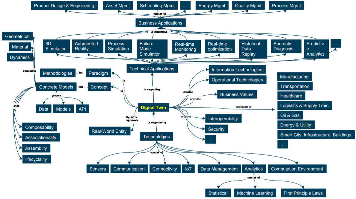
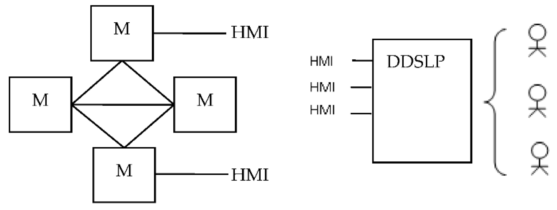
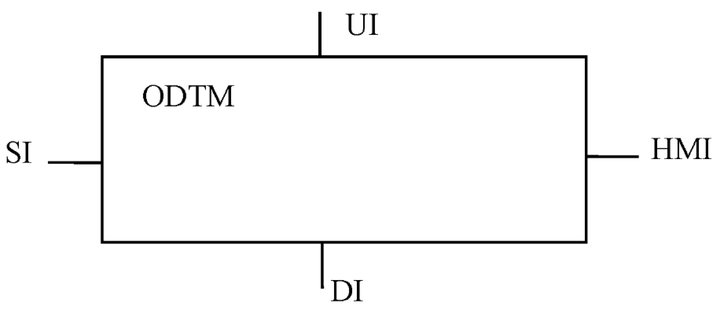
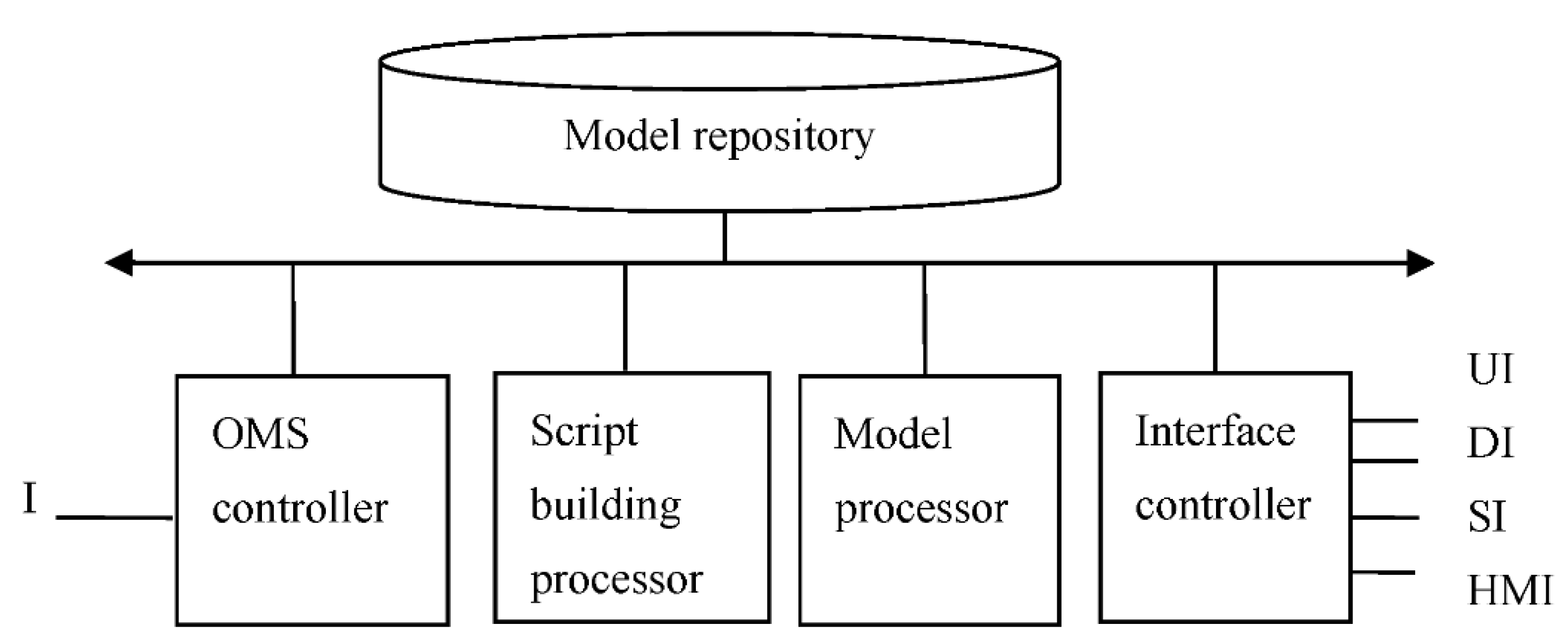
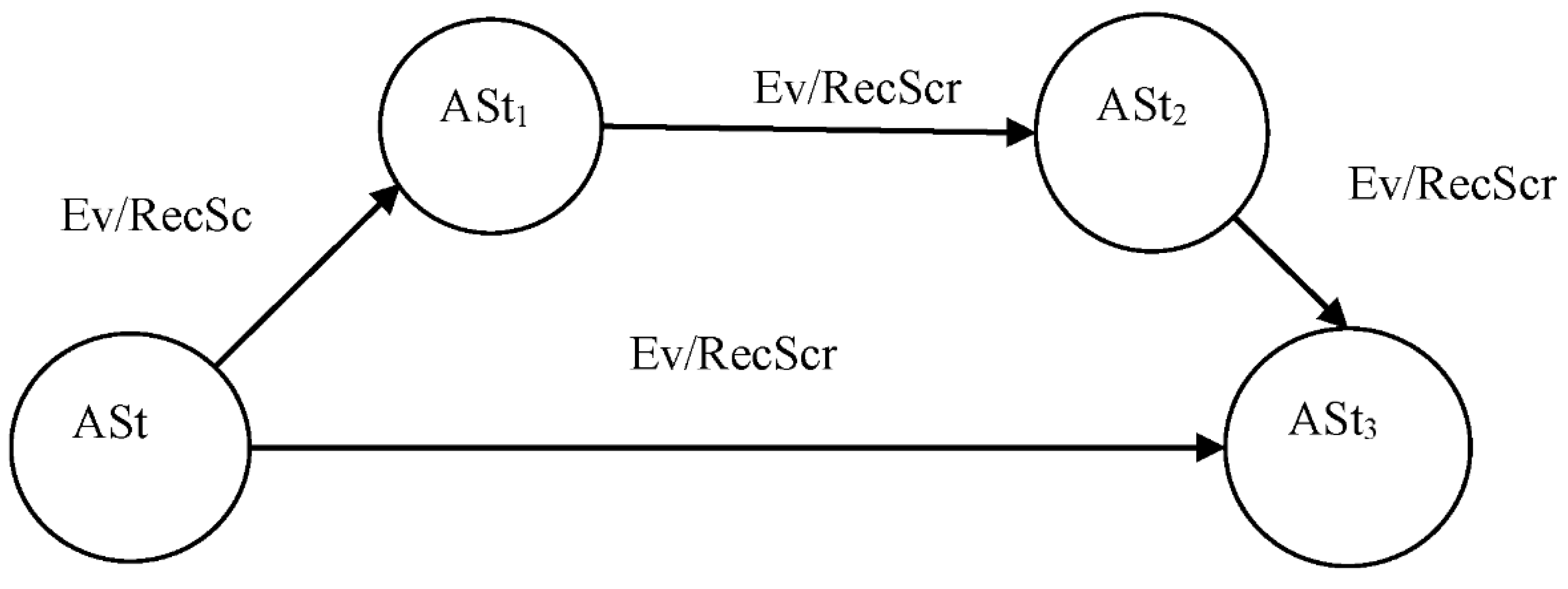
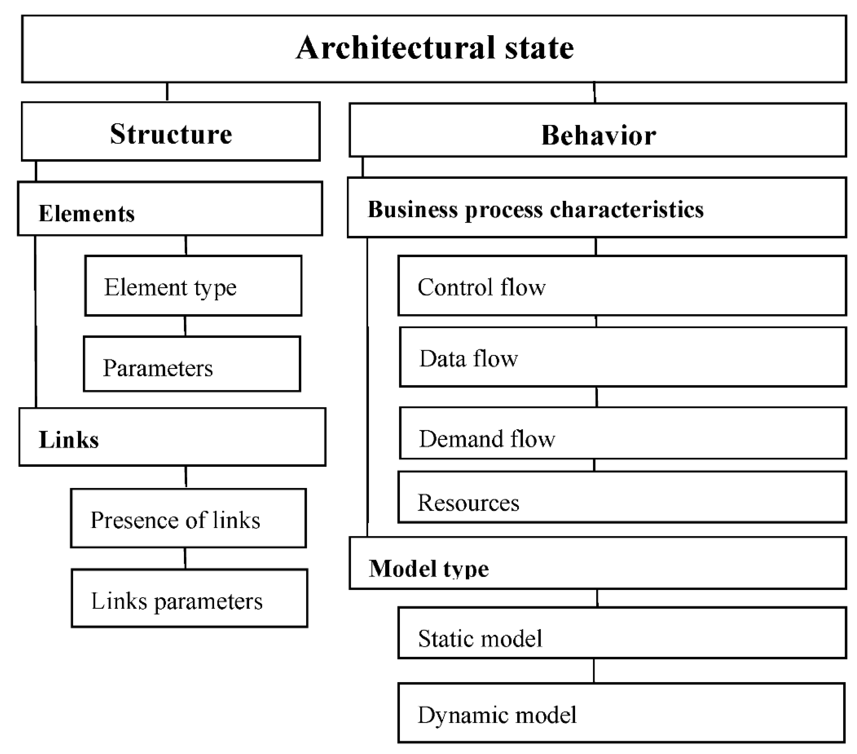
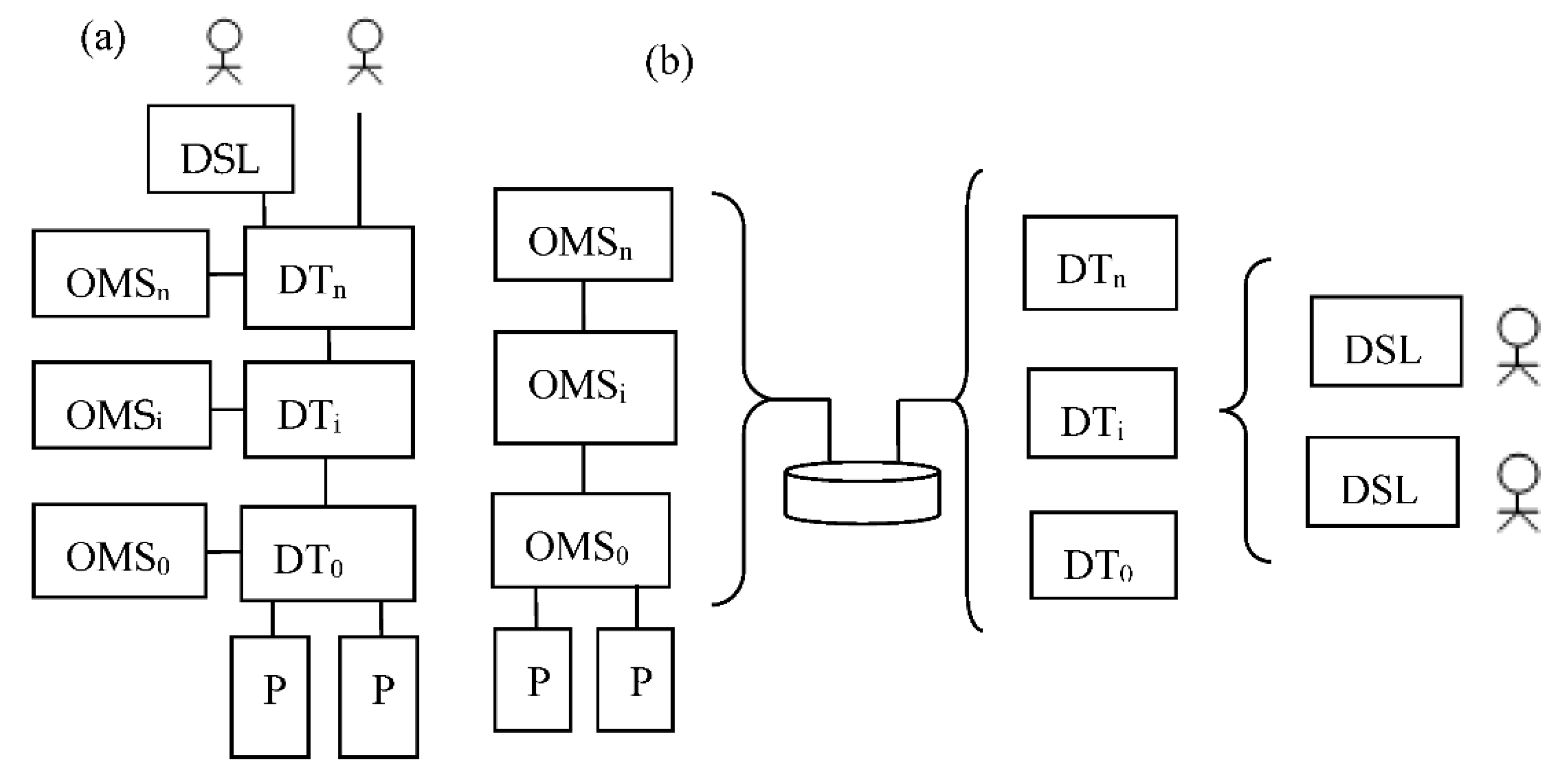
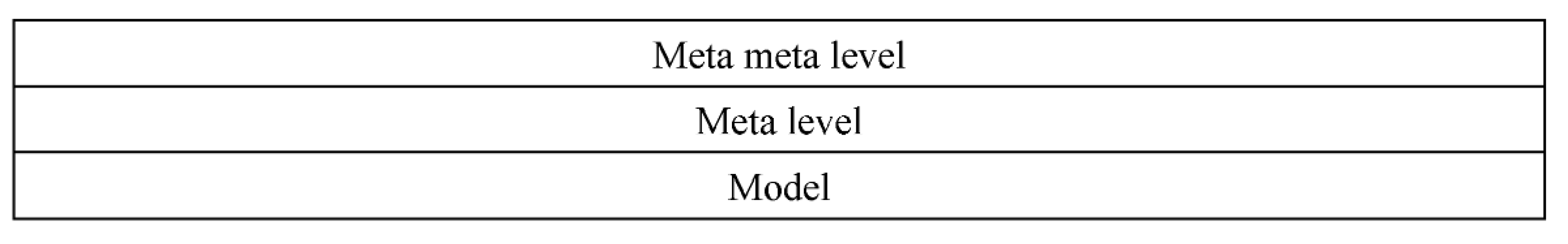
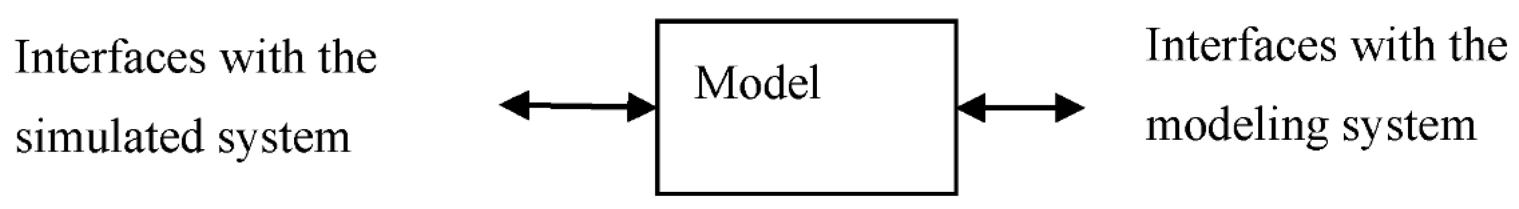
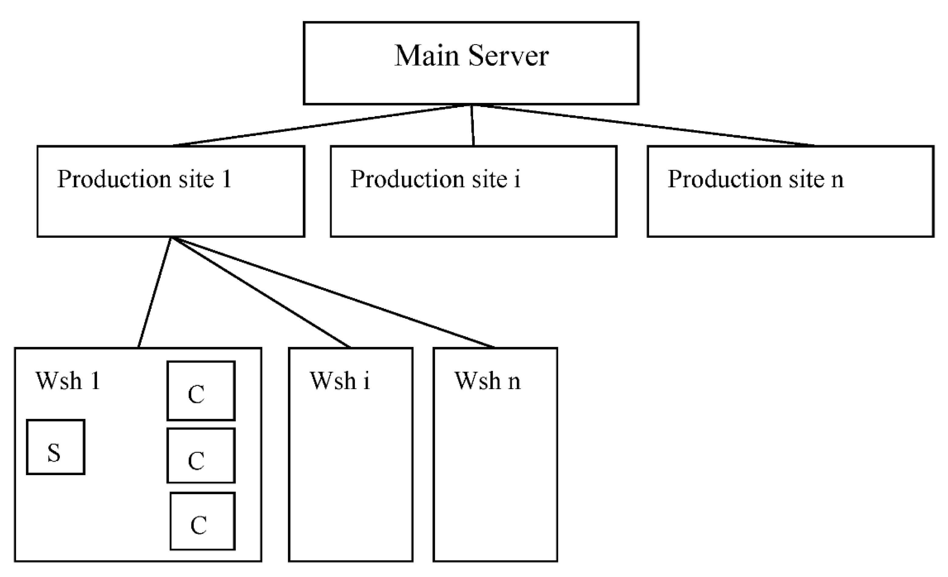
Table 1.
The use of MBA technologies at different stages of SwIS LS.
| No. | Stages | MBA Technologies |
|---|---|---|
| 1 | Development | Model Driven Architecture (MDA) [18], DevOPS [19], Agile Architecture (AA) [20,21], Digital Twins (DT) [22,23] |
| 2 | Production | DT, Model Driven Engineering [24] |
| 3 | Operating | DT, AA, containers [25], middleware, virtual machines [26] |
| 4 | Modernization | DevOPS, evolutionary architectures [15], IT Infrastructure Library/IT Service Management (ITIL/ITSM) [27] |
Table 2.
Main mapping types.
| Mapping Type | Examples |
|---|---|
| V → V (VV mapping) | Classic MW, Containers, Virtual Machines |
| V → P (VP mapping) | Digital Twins |
| P → P (PP mapping) | Physical Twins |
| V → B (VB mapping) | Virtual Hospital |
| V → S (VS mapping) | Social Network |
Table 3.
System modeling results NoN = 100,000.
| Number of Events | Treq, s | Trdf, s |
|---|---|---|
| 10,000 | 1 s | 21 s |
| 100,000 | 7 s | 198 s |
| 1,000,000 | 1 min, 29 s | 2542 s |
Table 4.
System modeling results NoN = 1000,000.
| Number of Events | Treq | Trdf |
|---|---|---|
| 100,000 | 2 s | 95.5 s |
| 1,000,000 | 14 s | 283 s |
| 10,000,000 | 2 min, 1 s | 2712 s |
Publisher’s Note: MDPI stays neutral with regard to jurisdictional claims in published maps and institutional affiliations. |
© 2022 by the authors. Licensee MDPI, Basel, Switzerland. This article is an open access article distributed under the terms and conditions of the Creative Commons Attribution (CC BY) license (https://creativecommons.org/licenses/by/4.0/).
Share and Cite
MDPI and ACS Style
Vodyaho, A.I.; Zhukova, N.A.; Shichkina, Y.A.; Anaam, F.; Abbas, S. About One Approach to Using Dynamic Models to Build Digital Twins. Designs 2022, 6, 25. https://doi.org/10.3390/designs6020025
AMA Style
Vodyaho AI, Zhukova NA, Shichkina YA, Anaam F, Abbas S. About One Approach to Using Dynamic Models to Build Digital Twins. Designs. 2022; 6(2):25. https://doi.org/10.3390/designs6020025
Chicago/Turabian StyleVodyaho, Alexander Ivanovich, Nataly Alexandrovna Zhukova, Yulia Alexandrovna Shichkina, Fahem Anaam, and Saddam Abbas. 2022. "About One Approach to Using Dynamic Models to Build Digital Twins" Designs 6, no. 2: 25. https://doi.org/10.3390/designs6020025