
Reference Generator for a System of Multiple Tethered Unmanned Aerial Vehicles


1
Center for Research and Advanced Studies of the National Polytechnic Institute, Mexico City 07360, Mexico
2
UNITEC Campus Cuitláhuac, Universidad Tecnológica de México, Mexico City 02870, Mexico
3
National Council for Science and Technology, Mexico City 07360, Mexico
4
HEUDIASYC CNRS, Université de Technologie de Compiègne, 60319 Compiegne, France
*
Author to whom correspondence should be addressed.
Drones 2022, 6(12), 390; https://doi.org/10.3390/drones6120390
Submission received: 27 October 2022
/
Revised: 25 November 2022
/
Accepted: 27 November 2022
/
Published: 1 December 2022
(This article belongs to the Special Issue Multi-UAVs Control)
Abstract
:This paper deals with the references generation for a team of unmanned aerial vehicles tethered to a ground station for inspection applications. In order to deploy the team of vehicles in a suitable location to cover the largest area, each vehicle is commanded to securely navigate in an area of interest while it is tethered to another vehicle or to a ground station. To generate the corresponding reference for each vehicle, we used a model predictive controller, which optimizes the desired trajectory based on the mission-defined constraints. To validate the effectiveness of the proposed strategy, we conducted a simulation and experimental tests with a team of consumer unmanned aerial vehicles tethered to a ground station.
1. Introduction
Unmanned aerial vehicles (UAVs) have been the center of interest between researchers due to their extensive field of application. At an early research stage, researchers developed algorithms for modeling and controlling different types of rotary-wing and fixed-wing aircraft [1]. Later, in the last decade, these vehicles began to be used in different applications, such as surveillance [2], transportation [3], and search and rescue missions [4,5].
Nowadays, UAVs can be classified in three different configurations [6]: rotary wing, fixed wing, and VTOL. Multirotors are a type of rotary-wing aircraft and are mainly used in tasks that exploit their versatility to carry out hover flight. The main disadvantages of these kind of vehicles are their endurance, due to the high current draw by the electric motors, and their low payload capability. Based on the type of application and the vehicle configuration to be used, there exist alternative power configurations that have been successfully implemented [7] to increment the endurance. A particular solution for rotary-wing aircraft is the so-called tethered power supply [8].
A multirotor tethered to a power source in the ground through an electrical wire allows the vehicle to increase its endurance providing unlimited power for long-time flights, establishing a jamming-resistant secure communication, and even providing the possibility to conduct 6G applications [9]. Moreover, the tether can be used for other applications, such as self-localization [10,11], underwater mapping [12], enhancing the hovering performance [13], and tether-guided landing [14].
One of the key aspects to be considered in order to use a tethered station is to conduct a power consumption analysis to determine the energy requirements for a specific drone [15,16]. Furthermore, besides the power source, a winch system is required to control the release and retraction of the tether cable.
1.1. Related Work
The authors in [8,17,18] analyzed and implemented tension control algorithms to maintain the tether cable taut. However, a disadvantage of the taut cable case is that the generated tension due to traction directly affects the vehicle’s payload capability, decreasing it significantly. A solution to avoid such a high tension is to leave the cable with a slight extra length, allowing it to hang loosely [19,20]. Having the cable slack can affect the vehicle dynamics due to the vibration behavior of the cable. In [21], this behavior was analyzed numerically. In addition, in [22], the authors analyzed and compensated a flow-induced force caused by a fluid-tethered aircraft.
Despite its long-flight endurance capability, a single vehicle tethered to a ground station has a limited coverage area constrained to the cable length. Furthermore, in a scenario where there is an obstacle through the planned path, the vehicle could elude it, but the tether cable must remain straight in the plane to avoid any edge that could damage the cable or disconnect it from the power source. A possible solution to overcome this issue and to increase the covered area is to use a system of multiple UAVs. However, this solution presents different challenges to be solved before using a team of tethered UAVs, such as to obtain a mathematical model of the whole system by considering the tension produced by the cable, either in the case when it is proposed to be always taut or it is considered that it can be hanging loosely. For instance, in [23], the authors developed a simplified expression of the dynamics of a chain of multiple tethered drones based on geometric mechanics by considering that the cable is mass-less and its elongation is negligible. They proposed an active device controller for the tether which controls the total cable length and tension due to traction.
When it is considered the cable is hanging loosely, a continuous evaluation of the tether shape must be computed in order to prevent the cable from touching the ground [24]. On the other hand, because the main function of the tether is to transmit power to the vehicle, depending on its size and weight, the cable mass becomes a crucial factor to be considered, because it could introduce disturbances to the UAV. In [25], the authors proposed an active winch system for a team of tethered drones in order to control the cable length from one vehicle to the next one. Although they considered that each winch has a variable mass as a function of the tether length, they did not consider the cable mass as a perturbation, which would lead to undesired linear displacements.
When the team of tethered UAVs has been set up, the whole system can be considered as a single entity that requires a path planner to command the team of vehicles to conduct a mission altogether. The path planner is responsible for generating a path free of obstacles for each UAV, starting from their initial position and taking them to a final target. Two types of approaches have been proposed to generate the desired paths: (i) the offline approach, where the reference path is computed at the beginning of the mission, and (ii) the online approach, where the reference path is actualized every specific time. In [26], the path planning incorporated the dynamics of the vehicle and used a nonlinear programming solver, while in [24], a graph search algorithm was used for the path planning of a team of tethered mobile robots. Working with a team of vehicles adds extra constraints to the system. In [27], the Hungarian algorithm was used for the trajectory planning of multiple UAVs with obstacle avoidance. Besides avoiding static obstacles, each vehicle was considered as a dynamic obstacle, so the offline approach was not suitable in this scenario. In [28], moving obstacles were considered and a collision-free navigation was based on the 3D vision method. In [29], an optimal path was defined for each mobile robot, which takes into account the sum of all the other paths. In addition, in the case of multiple tethered UAVs, the tether is also a restriction for the linear displacement of each vehicle. In [23], the authors used geometric control combined with model predictive control (MPC) to handle the tension and the length of the tether at all times. The MPC approach was used to maintain the tether taut [18]. The MPC, also known as a finite-horizon optimal control problem (FHOCP) approach, was widely used with single untethered [30,31], single tethered [32,33,34], and multi-tethered [23,25] UAVs due to its capability to deal with nonlinear constraints.
In this work, we consider the perturbation caused by the mass of the tether cable and propose a control algorithm to compensate it by computing both its shape as its tension force at each point of attachment. We use the MPC [25] to compute the next position reference for each UAV based on the closed-loop vehicle dynamics and the disaster zone constraints. Furthermore, because the MPC approach is also known for being computationally demanding, we selected suitable objective variables to improve the computational efficiency. For a more realistic scenario, in our proposal, we take into account both the cable mass and its sagging.
1.2. Contributions
The main contributions of this work are summarized as follows:
- The development of a navigation strategy based on the MPC for a chain of tethered UAVs to achieve inspection missions as a team.
- The implementation of the proposed strategy with a team of two aerial vehicles in a real scenario.
The rest of the paper is organized as follows. Section 2 presents the problem statement. Section 3 describes the preliminaries and the dynamic model of each vehicle in the tethered platform. Section 4 presents the proposed control laws for each vehicle and the derivation of the reference generator. Section 5 introduces the obtained results of the conducted simulation and experimental tests. Finally, in Section 6, the conclusions and future directions of our research work are presented.
2. Problem Statement
Consider the multi-agent platform composed of a team of M quadrotor vehicles tethered by cables with constant length depicted in Figure 1. It is desired to develop a navigation strategy that enables a chain of vehicles to reach a desired target coordinate in the 3D space. It is considered that the desired altitude and yaw orientation are fixed to a constant value. The ultimate goal is to generate the desired coordinates to simulate a scenario for a building inspection where the shape of the building to be inspected is unknown. However, an estimate of its maximum area with respect to its geometric center is assumed to be known.
The mathematical model of the complete system is analyzed from a single vehicle whose translational dynamics are perturbed by the tension in both cables, the one tethered to the next vehicle and the one tethered to the previous vehicle. In this sense, the tension due to the cable weight is analyzed first and then the mathematical model of a single UAV is developed.
3. Preliminaries
The objective of the following subsections is to compute the tension exerted on each vehicle due to the tethered cables and to obtain the dynamic equations of each vehicle in the platform by considering the effects of such tensions.
3.1. The Catenary Curve
A cable hanging loosely between two fixed attachments shapes a curve called catenary. The 3D analysis of this curve can be simplified to a 2D analysis with a rotation around the Z axis [35].
Let us consider a section of a cable hanging as shown in the free-body diagram of Figure 2, where W, L, and are the cable weight, length, and density, respectively. The parameter a represents the distance from the support A to the origin of the plane. The parameter describes the tension force at support A.
The equation that describes the catenary shape of the cable is given by [36] as:
Solving Equation (1) with respect to z and adding the y axis, we obtain:
with parameter a being . The cable length L is given by:
and the tension force exerted on the vehicle due to the cable can be found as:
From Equation (2), we can observe that the solution of the catenary equation depends on the parameter a. This parameter can be computed by using a numerical method such as the Halley method [35] which uses the following transcendental equation:
The tension forces acting on each vehicle due to the cable weight are transformed to spherical coordinates using attitude angles and as shown in Figure 3, and their magnitude depends on the cable length .
As can be seen in Figure 3, each UAV experiences resulting forces at each axis. In the X and Y axis, these forces are opposite, while in the Z axis, the resulting force is pulling down the vehicle. These tension forces are given by:
3.2. Tethered Quadrotor Dynamical Model
Let us consider the quadrotor vehicle shown in Figure 4. Let us define the inertial reference frame , with axes centered on the ground station (GS), and a body reference frame , with axes centered on the vehicle. It is assumed that both frames coincide with the center of mass (CoM) of the GS and the vehicle, respectively. We considered that the geometric center of the vehicle coincides with its CoM. The vehicle attitude is described by the roll, pitch, and yaw angles, given by , , and , respectively.
The control signals to command the dynamics of vehicle i are defined as , , , , which represent the total thrust and the angular acceleration at roll, pitch, and yaw, respectively. These control signals are given by the combination of each motor thrust , , which is proportional to the square of its angular velocity , as follows:
where d is the distance between the vehicle’s CoM and the rotor shaft, and c is the propeller-drag coefficient.
The equations of motion of each vehicle i are assumed as in [1], and including the tension force due to the tether cable, it yields:
where m is mass of the vehicle, g is the force due to gravity, and , , and are the coefficients of the main diagonal of the inertia matrix of vehicle i.
4. Main Result
The main results of this research work related to the multi-agent controller and to the reference generated are presented below.
4.1. Multi-Agent Controller
In view of their simplicity and convenience, we chose the consumer drones DJI Tello EDU to conduct the experimental test. These UAVs have built-in hovering controllers, allowing users to manually fly them using a radio remote controller, leaving the translational dynamics to be controlled either by the user or by sending a signal computed in an external device.
In our experimental platform, we fixed the altitude and the yaw angle at a constant value, and considering that the remaining attitude dynamics are stabilized, the mathematical model given by Equations (13)–(18) can be simplified as:
where and are the position and linear velocity vectors on the body inertial frame, is the gain matrix of the controller, , and are the position and linear velocity reference vectors. Finally, is the disturbance due to the cable weight.
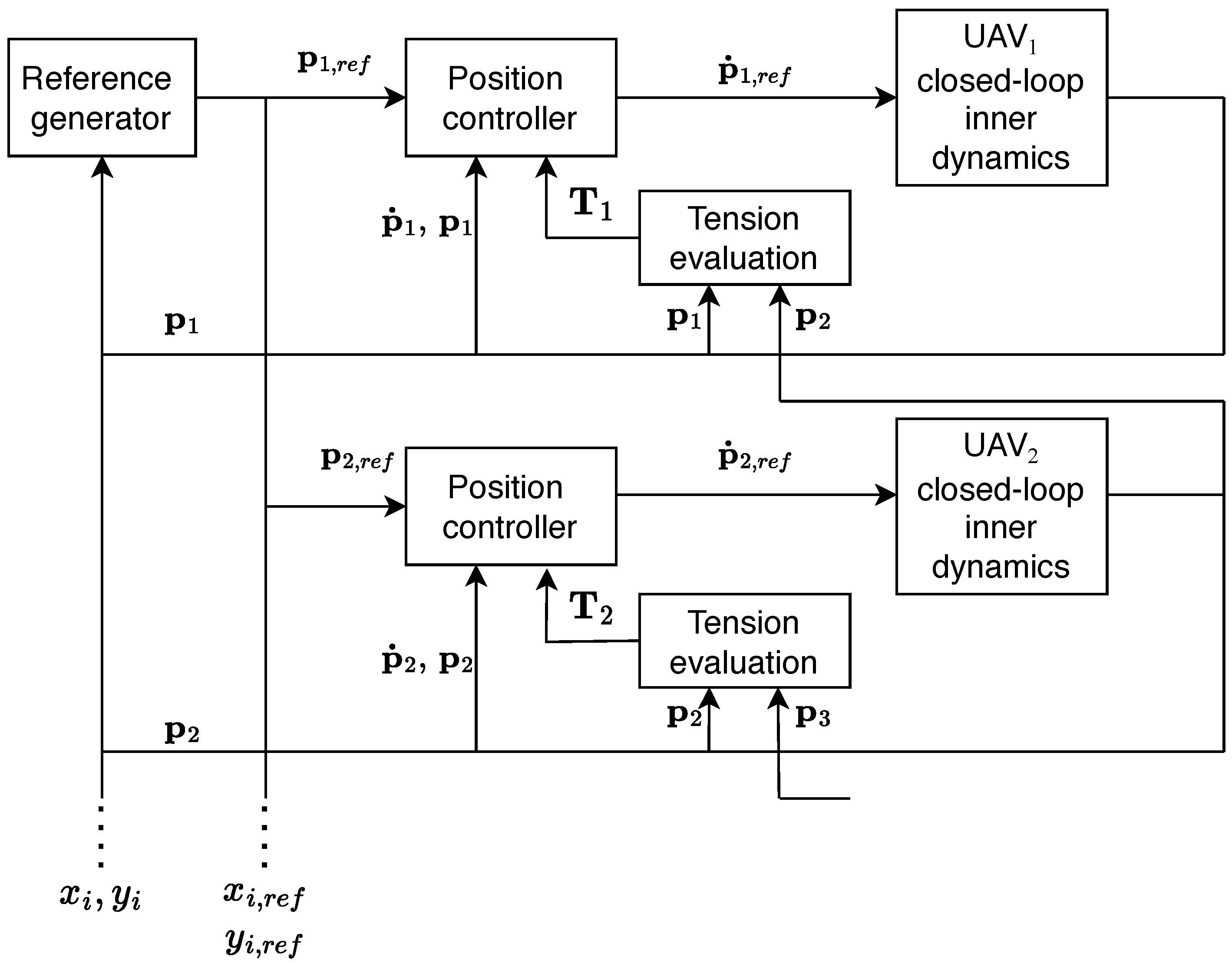
Figure 5 depicts the interaction of the different components of the resulting multi-agent system. At the outermost loop, a reference generator computes the next x and y references for each vehicle, and then a position controller is used to transform the generated references into suitable command velocities which are finally sent to each UAV.
The position controller shown in Figure 5 is chosen as a PI plus tension compensator controller, Equation (20). The generated references are under the integral term of this controller:
Equation (20) is used to transform the system given by Equation (19) in order to take as inputs the linear position references instead of the linear velocity references, which yields:
By defining the position error , and its first and second time derivatives, , , Equation (21) yields
A suitable choice of in Equation (22) would conduce the error dynamics to be Hurwitz stable. Finally, because the proposed command velocity vector is expressed in the inertial frame, it must first be expressed with respect to the body frame by using the following transformation:
4.2. Reference Generator
The purpose of the reference generator is to provide the necessary references to deploy the tethered quadrotors from an initial position to a desired position. To generate the references for each vehicle at each time step, we used the MPC approach.
The MPC approach can be described as follows: Starting from a current measured state , a nonlinear constrained optimization problem is solved over a fixed future interval N by considering the current and future states and constraints, respectively. The algorithm outputs the future optimal references for the next steps, and only the first reference is applied to the system. The state is measured at time , and then, the algorithm is repeated [37].
To implement this approach, we require a discrete version of the mathematical model of the system. Because in the reduced model of the system given in Equation (19) gain K is an unknown parameter, we used the system identification process described in Appendix A to identify the dynamics of a single vehicle given in Equation (A3). For multiple vehicles, Equation (A3) can be extended as:
being , where , , , , …, , , , . is the discrete matrix that contains the closed-loop poles of the system, and is the discrete matrix associated with the linear position references. The algorithm was solved by using the MATLAB function fmincon. The remaining parts of the MPC approach related to the optimization variables, the cost function, and the system constraints are presented in the following subsections.
4.2.1. Optimization Variables
A natural selection of the optimization variables would be the position references [25]. However, in an implementation of this approach in an embedded device, this choice will consume extra memory because the optimization variables are saved for the next step as initial conditions of the algorithm, which could be a problem for devices with limited resources. A more suitable selection is to define the increments of the position references as the optimization variables, because in this way, the initial conditions for the next step are always zero and there is no need to save the optimization variables at each step.
Moreover, by choosing the increments of the references as the optimization variables, their initial bounds can be defined by using:
and, consequently, the feasible set is reduced. Here, and are the lower and maximum reference displacements with respect to the previous one, respectively.
4.2.2. Cost Function
The cost function used in this approach is given by:
where functions F and G are the terminal and stage cost, respectively, and are defined as follows:
being a weighting factor. Because each vehicle has a desired target position, we defined the cost function as the squared Euclidean norm of the error between the target position and the UAV current state.
4.2.3. System Constraints
The tethered multi-agent system presents two types of constraints, : (i) the one related to the distance between the obstacle and the position of each UAV with their corresponding tether cable defined as , and (ii) the one related to the distance between vehicles , which is defined based on the maximum length of the tether cable and the minimum safety distance between vehicles. A large distance between vehicles would exceed the length of the tether cable, causing a possible disconnection or a large perturbation that could destabilize the vehicle. Similarly, a small distance could cause a collision between vehicles.
Otherwise, the tether cable by itself represents a constraint, because it must also remain outside a safety distance with respect to the object area at all times. The cable length is equally partitioned in n segments, where each node represents a constraint, including the nodes corresponding to the supports of the tether cable placed at each pair of vehicles. These partitions are defined as follows:
where the parameter denotes the normalized segment partition, .
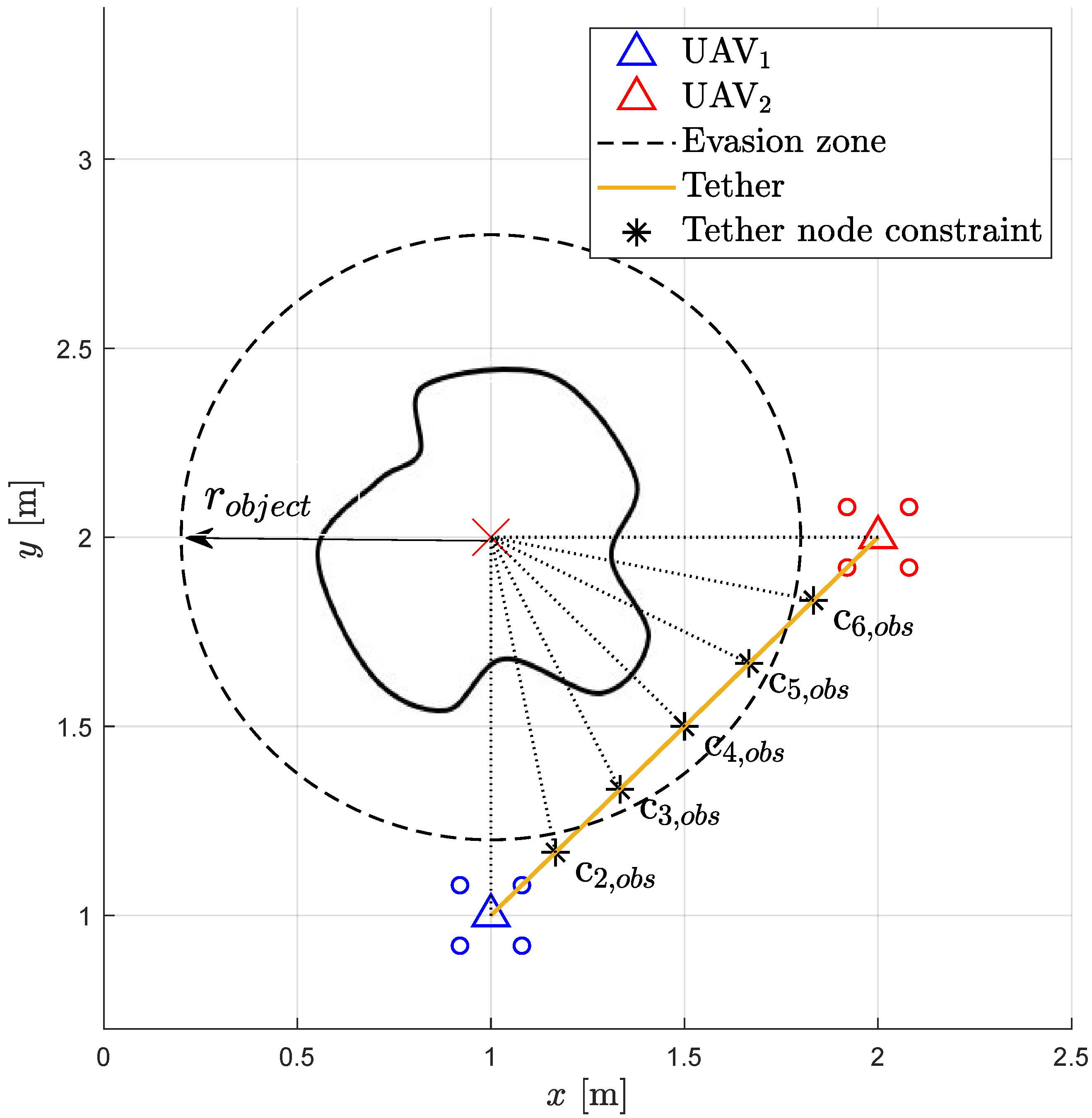
Figure 6 depicts an example of a tether cable divided in six segments, resulting in seven equally spaced constraints, where three of them are not satisfying the minimum obstacle safety radius.
The constraints related to the safety distance between UAVs are defined as follows:
where is the minimum safety distance between two UAVs, defined by the vehicle size plus an extra safety distance, and is the length of the tether cable minus a small distance to let the cable sag.
Finally, the system constraints can be summarized as follows:
where is the coordinate representing the center of the object to be inspected.
5. Simulation and Experimental Results
In order to validate the proposed algorithms, we conducted a simulation and experimental tests with a team of three and two multirotor vehicles, respectively.
5.1. Simulation Results
For the simulation test, we defined the following scenario. We considered three UAVs tethered in a series by using two cables with a constant length. The vehicles flight at a constant altitude and with a constant yaw angle. The vehicles start the mission from an initial coordinate in the plane. The inspection mission consists of carrying the team of UAVs to a target position defined for each vehicle while they are satisfying the constraints related to the shape of the building to be inspected as well as the system constraints. If one or more vehicles stop working, the other ones will continue their references until they reach the maximum tether length with respect to the vehicle that is not working. Because this length is a constraint, the algorithm will fall in a loop trying to reach the target while it satisfies the tether length constraint. In this scenario, the user has to stop the execution of the algorithm.
We used the MPC approach to predict steps at each discrete step, where the matrix optimization variable, , was computed by solving the nonlinear optimization problem. The cost function was selected as in Equation (26), where the discrete-time mathematical model identified in Appendix A was used. The lower and upper bounds for Equation (25) were defined as cm and cm, respectively.
The constraint function given in Equation (34) was built by considering the following constraints: (i) an upper bound for the constant length of the tether cable and a lower bound for a safety distance to keep the UAVs within a fixed range and (ii) the constraints of each UAV and their tethers to avoid a collision with the building to be inspected by using four partitions for the tether cable given by Equation (32).
Figure 7 depicts the obtained MPC reference for each UAV. We can see that when the vehicles are close to the object (building) radius, the reference generator computes an attraction and repulsion reference, respectively, in order to satisfy both the constraints as the reference targets.
5.2. Experimental Results
To carry out the experimental test, we first adjusted two parameters: (i) the frequency of the reference generator and (ii) the bounds of the objective variables. By adjusting these parameters, the time for reaching the desired target of the system can be manipulated. Because this time is not a mission requirement, we adjusted these parameters to give us a smooth response by letting the reference reach a steady state at each step time. To choose the frequency of the reference generator, we based it on the settling time of the step response obtained in the identification system (around two seconds). At this time, the velocity is close to zero, and it is easy to match the initial conditions of the next step. In order to analyze the performance of the proposed methodology, we conducted a different test with smaller reference times for the generator.
Each conducted test can be summarized in the following steps: UAVs connection. Each vehicle is connected to the PC by using USB Wi-Fi adapters. Algorithm initialization. Once all the hardware connections are finalized, we run the main ROS node. This node runs continuously during each test and it is composed of two flight modes: the stabilize mode and the reference generator mode. The stabilize mode runs by default, allowing to fly the vehicles manually by using a joystick and self-leveling the roll and pitch axis. In this mode, each fly command sent by the joystick is repeated to each vehicle. This mode also allows to send to each vehicle special commands, such as takeoff and landing. The reference generator mode is activated when the vehicles are in hover flight. Once this mode is running, the vehicles continuously receive and execute the commands sent by the reference generator. Finalization. Once the vehicles have reached the desired target, we switch to the stabilize mode where the vehicles receive the landing command. Figure 8 depicts the described set up.
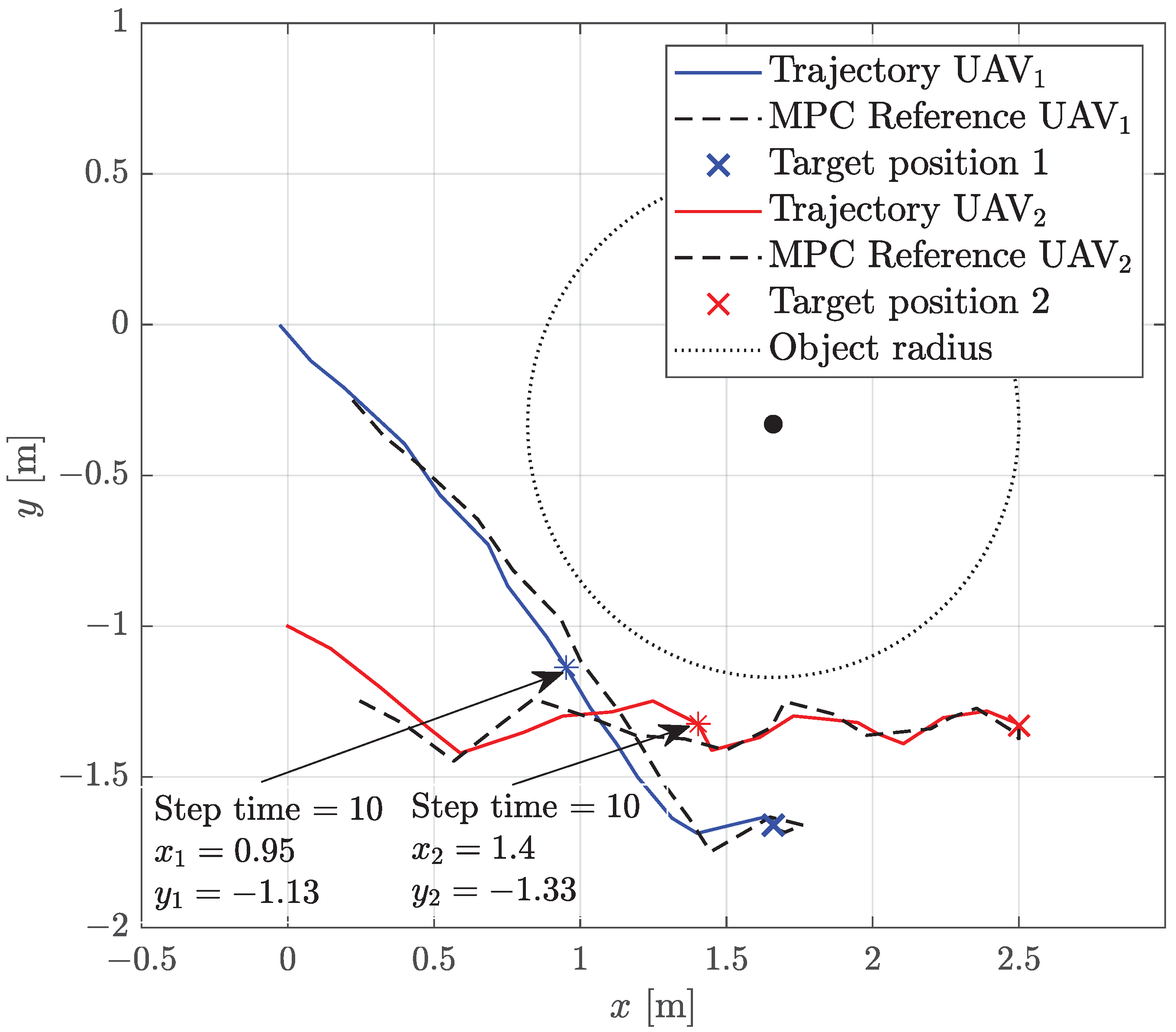
The experimental scenario was defined as follows: The vehicles are tethered by a cable with a constant length of 2 meters. Both vehicles have to reach a desired target coordinate given by m, m, m, and m, respectively. The desired altitude and yaw orientation are fixed to a constant value. Both desired coordinates were defined to simulate a realistic scenario for a building inspection as shown in Figure 1. Because in the experimental test it is considered that the shape of the building to be inspected is unknown, we suppose that at least we have an estimate of its maximum area with respect to its geometric center. In this sense, we defined a radio composed of the radio of such an area plus a security distance in order to specify a circumference which the vehicles have to avoid while moving to the desired target positions. Figure 9 depicts the trajectory followed by each vehicle with respect to the waypoints obtained from the references generator. It is possible to see how the trajectories of both vehicles avoid the defined circumference until reaching the desired target positions.
Figure 10a,b, respectively, emphasize the behavior of the obtained trajectories for each vehicle in the X and Y axes with respect to the desired MPC references computed by the reference generator every two seconds. We can see that at each MPC reference, the translational dynamic as a similar behavior to the one identified in Appendix A. Despite there being small errors to reach the MPC references, we can observe that both vehicles reached the desired target positions.
Figure 11 shows how both vehicles satisfy the constrains defined by Equation (34). Figure 11a depicts the behavior of the constraints for the two vehicles and a tether cable partitioned in six segments in order to guarantee that the cable does not touch the obstacle radius. Figure 11b depicts the constraints to keep the two vehicles within a distance range, where the upper bound is the maximum length of the tether cable and the lower bound is the minimum distance between the UAVs.
5.3. Discussion
In contrast to the published works related to controlling a team of multiple tethered vehicles, such as that presented in [23,25], where the tether is considered as a taut cable, the strategies proposed in this research work consider a more realistic scenario where the tether is considered as a slack cable. In addition, we showed by conducting both a simulation as well as experimental tests, by using two tethered drones, that the proposed strategies guarantee the mission success despite the expected position errors of each vehicle caused by the employed estimation system based on the visual odometry.
6. Conclusions and Future Work
The proposed strategy for references generation for a team of UAVs in a scenario subject to physical constrains was successfully implemented. It was shown by the experimental tests that a team of two vehicles can reach a desired target by following the references generated by using the MPC approach while they are dealing with two types of constrains related to avoiding the obstacle minimum safety distance and the other one related to keeping the vehicles within a safety distance between them.
The selection of the optimization variables reduced the computational cost and, consequently, the algorithm found the optimal reference values in a faster time.
The numerical results, depicted in Figure 9 and Figure 10a,b, showed that at a steady state each reference presented maximum errors of ±0.2 cm. Theses errors were expected, because the position of each vehicle is estimated by using an odometry algorithm.
On the one hand, the system performance is affected by the choice of the optimization variables bounds. In our scenario, we selected the smaller allowed ones as ±0.2 m. A selection of even smaller ones would cause issues at the path planning, because there is an expected error of ±0.2 m and the vehicles could fall in a dead zone. The selection of larger bounds would induce a faster response of the vehicles to reach the MPC references. However, if the bound is large enough, the vehicles could collide between them. As a rule of thumb, the selection of the optimization variables bounds are mainly based on the inspection area and the number of employed UAVs. On the other hand, the system performance is also modified by the frequency of the MPC reference loop. We defined this frequency based on the step response of the identified model.
A suitable value is to define the frequency of the MPC reference loop based on the settling time , as , such that the next MPC references are computed once each vehicle has reached the previous references. Moreover, choosing the settling time as the frequency parameter of the MPC reference generator guarantees that, at this time, the vehicle velocities are zero and, consequently, at the next discrete time the initial conditions of the discretized model will also be zero.
Finally, it is also possible to define smaller times than the settling time for the frequency of the reference generator; however, as the system response has not reached a steady-state value, the vehicle velocities are not constant and must be known in order to be used as the initial conditions of the discrete-time system.
If one or more vehicles stop working, the other ones will continue their references until they reach the maximum tether length with respect to the not working vehicle, because this length is a constraint, and the algorithm will fall in a loop pushing to reach the objective target and pulling to satisfy the tether length constraint. At this scenario, the user has to stop the algorithm.
The future directions of this work will consider a more realistic scenario. For this purpose, a tether cable with variable lengths and an actuated winch system will be considered. The covered area will be extended with an irregular three-dimensional object. We will also increase the number of UAVs to accomplish a more complex inspection mission.
Author Contributions
Conceptualization, R.L and E.S.E.; methodology, C.G.V. and E.S.E.; software, C.G.V. and N.A.; validation, C.G.V. and N.A.; formal analysis, C.G.V. and E.S.E.; investigation, C.G.V. and E.S.E.; resources, R.L and E.S.E.; writing—original draft preparation, C.G.V. and E.S.E.; writing—review and editing, C.G.V., E.S.E., and R.L.; visualization, C.G.V. and N.A.; supervision, E.S.E. and R.L.; project administration, E.S.E. and R.L.; funding acquisition, E.S.E. and R.L. All authors have read and agreed to the published version of the manuscript.
Funding
This work was partially supported by the Mexican National Council for Science and Technology through Project: Laboratorio Nacional en Vehículos Autónomos y Exoesqueletos.
Data Availability Statement
Not applicable.
Conflicts of Interest
The authors declare no conflict of interest.
Appendix A
In order to design the MPC, it is required to obtain a closed-loop discrete model of the vehicles considered for the experimental test. For this purpose, we identified a linear model of the translational dynamics of each vehicle by using a methodology previously reported in [38]. Figure A1 depicts the obtained step response for the X axis.
Once we have obtained the information of the step response for the translational dynamics, we used the MATLAB function tfest to identify a model of the system in the X axis, which requires the input, the output, and the sampling time used in the experimental test, as well as the number of poles of the desired transfer function to output the identified model as a transfer function given by:
For the translational dynamics in the Y axis, we used the same methodology to identify the corresponding transfer function. By defining the state variables as , , , and , and by using Equation (A1), the model is rewritten in the state-space form:
as:
with time t discretized as , where is the time instant and T is the sample time.
Using Euler’s method to discretize Equation (A2) yields:
where , and is the identity matrix.
Figure A1.
Step response of the system.

References
- Garcia, P.C.; Lozano, R.; Dzul, A.E. Modelling and Control of Mini-Flying Machines; Springer Science & Business Media: Berlin/Heidelberg, Germany, 2005. [Google Scholar]
- Wu, Y.; Wu, S.; Hu, X. Multi-constrained cooperative path planning of multiple drones for persistent surveillance in urban environments. Complex Intell. Syst. 2021, 7, 1633–1647. [Google Scholar] [CrossRef]
- Cardona, G.; Tellez-Castro, D.; Mojica-Nava, E. Cooperative transportation of a cable-suspended load by multiple quadrotors. IFAC-PapersOnLine 2019, 52, 145–150. [Google Scholar] [CrossRef]
- Pratt, K.S.; Murphy, R.R.; Burke, J.L.; Craighead, J.; Griffin, C.; Stover, S. Use of tethered small unmanned aerial system at berkman plaza ii collapse. In Proceedings of the 2008 IEEE International Workshop on Safety, Security and Rescue Robotics, Sendai, Japan, 21–24 October 2008; pp. 134–139. [Google Scholar]
- Xu, Z.; Yang, J.; Peng, C.; Wu, Y.; Jiang, X.; Li, R.; Zheng, Y.; Gao, Y.; Liu, S.; Tian, B. Development of an UAS for post-earthquake disaster surveying and its application in Ms7. 0 Lushan Earthquake, Sichuan, China. Comput. Geosci. 2014, 68, 22–30. [Google Scholar] [CrossRef]
- Shakhatreh, H.; Sawalmeh, A.H.; Al-Fuqaha, A.; Dou, Z.; Almaita, E.; Khalil, I.; Othman, N.S.; Khreishah, A.; Guizani, M. Unmanned aerial vehicles (UAVs): A survey on civil applications and key research challenges. IEEE Access 2019, 7, 48572–48634. [Google Scholar] [CrossRef]
- Boukoberine, M.N.; Zhou, Z.; Benbouzid, M. A critical review on unmanned aerial vehicles power supply and energy management: Solutions, strategies, and prospects. Appl. Energy 2019, 255, 113823. [Google Scholar] [CrossRef]
- Zikou, L.; Papachristos, C.; Tzes, A. The power-over-tether system for powering small UAVs: Tethering-line tension control synthesis. In Proceedings of the 2015 23rd Mediterranean Conference on Control and Automation (MED), Torremolinos, Spain, 16–19 June 2015; pp. 681–687. [Google Scholar]
- Kishk, M.; Bader, A.; Alouini, M.S. Aerial base station deployment in 6G cellular networks using tethered drones: The mobility and endurance tradeoff. IEEE Veh. Technol. Mag. 2020, 15, 103–111. [Google Scholar] [CrossRef]
- Al-Radaideh, A.; Sun, L. Self-Localization of Tethered Drones without a Cable Force Sensor in GPS-Denied Environments. Drones 2021, 5, 135. [Google Scholar] [CrossRef]
- Xiao, X.; Fan, Y.; Dufek, J.; Murphy, R. Indoor uav localization using a tether. In Proceedings of the 2018 IEEE International Symposium on Safety, Security, and Rescue Robotics (SSRR), Philadelphia, PA, USA, 6–8 August 2018; pp. 1–6. [Google Scholar]
- Diaz, A.L.; Ortega, A.E.; Tingle, H.; Pulido, A.; Cordero, O.; Nelson, M.; Cocoves, N.E.; Shin, J.; Carthy, R.R.; Wilkinson, B.E.; et al. The Bathy-Drone: An Autonomous Uncrewed Drone-Tethered Sonar System. Drones 2022, 6, 294. [Google Scholar] [CrossRef]
- Sandino, L.A.; Santamaria, D.; Bejar, M.; Kondak, K.; Viguria, A.; Ollero, A. First experimental results on enhancing hovering performance of unmanned helicopters by using a tethered setup. Robot. Auton. Syst. 2016, 79, 147–155. [Google Scholar] [CrossRef]
- Oh, S.R.; Pathak, K.; Agrawal, S.K.; Pota, H.R.; Garratt, M. Approaches for a tether-guided landing of an autonomous helicopter. IEEE Trans. Robot. 2006, 22, 536–544. [Google Scholar]
- Chang, K.H.; Hung, S.K. Design and Implementation of a Tether-Powered Hexacopter for Long Endurance Missions. Appl. Sci. 2021, 11, 11887. [Google Scholar] [CrossRef]
- Jain, K.P.; Kotaru, P.; de Sa, M.; Mueller, M.W.; Sreenath, K. Tethered Power Supply for Quadcopters: Architecture, Analysis and Experiments. arXiv 2022, arXiv:2203.08180. [Google Scholar]
- Lupashin, S.; D’Andrea, R. Stabilization of a flying vehicle on a taut tether using inertial sensing. In Proceedings of the 2013 IEEE/RSJ International Conference on Intelligent Robots and Systems, Tokyo, Japan, 3–7 November 2013; pp. 2432–2438. [Google Scholar]
- Nicotra, M.M.; Naldi, R.; Garone, E. Taut cable control of a tethered UAV. IFAC Proc. Vol. 2014, 47, 3190–3195. [Google Scholar] [CrossRef] [Green Version]
- Talke, K.A.; De Oliveira, M.; Bewley, T. Catenary Tether Shape Analysis for a UAV-USV Team. In Proceedings of the 2018 IEEE/RSJ International Conference on Intelligent Robots and Systems (IROS), Madrid, Spain, 1–5 October 2018; pp. 7803–7809. [Google Scholar]
- Valerio, C.G.; Espinoza, E.S.; Lozano, R. Control and cable deployment of a tethered PVTOL aircraft. In Proceedings of the 2021 18th International Conference on Electrical Engineering, Computing Science and Automatic Control (CCE), Mexico City, Mexico, 9–11 November 2021; pp. 1–6. [Google Scholar]
- Tao, Y.; Zhang, S. Research on the Vibration and Wave Propagation in Ship-Borne Tethered UAV Using Stress Wave Method. Drones 2022, 6, 349. [Google Scholar] [CrossRef]
- Lee, S.M.; Ng, W.H.; Liu, J.; Wong, S.K.; Srigrarom, S.; Foong, S. Flow-Induced Force Modeling and Active Compensation for a Fluid-Tethered Multirotor Aerial Craft during Pressurised Jetting. Drones 2022, 6, 88. [Google Scholar] [CrossRef]
- Kosarnovsky, B.; Arogeti, S. Geometric and constrained control for a string of tethered drones. Robot. Auton. Syst. 2020, 133, 103609. [Google Scholar] [CrossRef]
- Caruso, M.; Gallina, P.; Seriani, S. On the Modelling of Tethered Mobile Robots as Redundant Manipulators. Robotics 2021, 10, 81. [Google Scholar] [CrossRef]
- Fagiano, L. Systems of tethered multicopters: Modeling and control design. IFAC-PapersOnLine 2017, 50, 4610–4615. [Google Scholar] [CrossRef]
- Hassani, V.; Lande, S.V. Path planning for marine vehicles using Bézier curves. IFAC-PapersOnLine 2018, 51, 305–310. [Google Scholar] [CrossRef]
- Zhang, J.; Sheng, H.; Chen, Q.; Zhou, H.; Yin, B.; Li, J.; Li, M. A Four-Dimensional Space-Time Automatic Obstacle Avoidance Trajectory Planning Method for Multi-UAV Cooperative Formation Flight. Drones 2022, 6, 192. [Google Scholar] [CrossRef]
- Ming, Z.; Huang, H. A 3d vision cone based method for collision free navigation of a quadcopter UAV among moving obstacles. Drones 2021, 5, 134. [Google Scholar] [CrossRef]
- Škrjanc, I.; Klančar, G. Optimal cooperative collision avoidance between multiple robots based on Bernstein–Bézier curves. Robot. Auton. Syst. 2010, 58, 1–9. [Google Scholar] [CrossRef]
- Feng, Y.; Zhang, C.; Baek, S.; Rawashdeh, S.; Mohammadi, A. Autonomous landing of a UAV on a moving platform using model predictive control. Drones 2018, 2, 34. [Google Scholar] [CrossRef] [Green Version]
- Sajjadi, S.; Mehrandezh, M.; Janabi-Sharifi, F. A Cascaded and Adaptive Visual Predictive Control Approach for Real-Time Dynamic Visual Servoing. Drones 2022, 6, 127. [Google Scholar] [CrossRef]
- Glick, T.; Arogeti, S. Control of tethered drones with state and input constraints-a unified model approach. In Proceedings of the 2018 International Conference on Unmanned Aircraft Systems (ICUAS), Dallas, TX, USA, 12–15 June 2018; pp. 995–1002. [Google Scholar]
- Saccani, D.; Fagiano, L. Autonomous uav navigation in an unknown environment via multi-trajectory model predictive control. In Proceedings of the 2021 European Control Conference (ECC), Rotterdam, The Netherlands, 29 June–2 July 2021; pp. 1577–1582. [Google Scholar]
- Rossi, E.; Bruschetta, M.; Carli, R.; Chen, Y.; Farina, M. Online nonlinear model predictive control for tethered uavs to perform a safe and constrained maneuver. In Proceedings of the 2019 18th European Control Conference (ECC), Naples, Italy, 25–28 June 2019; pp. 3996–4001. [Google Scholar]
- Sagliano, M.; Theil, S.; Schramm, J.; Schwarzwald, M. Modeling of a Tethered Testbed for a VTVL Vehicle. Model. Simul. Eng. 2020, 2020, 8523514. [Google Scholar] [CrossRef]
- Lockwood, E. Chapter 13: The tractrix and catenary. In A Book of Curves; Cambridge University Press: Cambridge, UK, 1961. [Google Scholar]
- Goodwin, G.; Seron, M.M.; De Doná, J.A. Constrained Control and Estimation: An Optimisation Approach; Springer Science & Business Media: Berlin/Heidelberg, Germany, 2006. [Google Scholar]
- Ortega, G.; Muñoz, F.; Espinoza, E.S.; Garcia, L.R.; Ordaz, P. Implementation of leader-follower linear consensus algorithm for coordination of multiple aircrafts. In Proceedings of the 2015 Workshop on Research, Education and Development of Unmanned Aerial Systems (RED-UAS), Cancún, Mexico, 23–25 November 2015; pp. 25–32. [Google Scholar]
Figure 1.
Sketch of a platform application.

Figure 2.
Free-body diagram of the catenary curve hanging from the supports A and B.

Figure 3.
Free-body diagram of the tension force.

Figure 4.
Free-body diagram of each tethered quadrotor.

Figure 5.
Block diagram of the multi-agent controller and reference generator.

Figure 6.
Tether cable as a constraint.

Figure 7.
Trajectories of the three tethered UAVs in the simulation test.

Figure 8.
Block diagram setup of the system.

Figure 9.
Trajectories of the two tethered UAVs.

Figure 10.
Performance of both vehicles in the X and Y axes. (a) Behavior in the X axis of both UAVs. (b) Behavior in the Y axis of both UAVs.
Figure 10.
Performance of both vehicles in the X and Y axes. (a) Behavior in the X axis of both UAVs. (b) Behavior in the Y axis of both UAVs.

Figure 11.
System constraints. (a) Obstacle avoidance constraints. (b) UAVs safety distance constraints.
Figure 11.
System constraints. (a) Obstacle avoidance constraints. (b) UAVs safety distance constraints.

Publisher’s Note: MDPI stays neutral with regard to jurisdictional claims in published maps and institutional affiliations. |
© 2022 by the authors. Licensee MDPI, Basel, Switzerland. This article is an open access article distributed under the terms and conditions of the Creative Commons Attribution (CC BY) license (https://creativecommons.org/licenses/by/4.0/).
Share and Cite
MDPI and ACS Style
Valerio, C.G.; Aguillón, N.; Espinoza, E.S.; Lozano, R. Reference Generator for a System of Multiple Tethered Unmanned Aerial Vehicles. Drones 2022, 6, 390. https://doi.org/10.3390/drones6120390
AMA Style
Valerio CG, Aguillón N, Espinoza ES, Lozano R. Reference Generator for a System of Multiple Tethered Unmanned Aerial Vehicles. Drones. 2022; 6(12):390. https://doi.org/10.3390/drones6120390
Chicago/Turabian StyleValerio, Carlos G., Néstor Aguillón, Eduardo S. Espinoza, and Rogelio Lozano. 2022. "Reference Generator for a System of Multiple Tethered Unmanned Aerial Vehicles" Drones 6, no. 12: 390. https://doi.org/10.3390/drones6120390