
Design of a Dual-Mode Input Structure for K/Ka-Band Gyrotron TWT
by

Mengshi Ma
1, 
Qixiang Zhao
1,*,
Kunshan Mo
1,
Shuquan Zheng
1,
Lin Peng
1,
You Lv
1 and
Jinjun Feng
2 1
School of Information and Communication, Guilin University of Electronic Technology, Guilin 541004, China
2
National Key Laboratory of Science and Technology on Vacuum Electronics, Beijing Vacuum Electronics Research Institute, Beijing 100015, China
*
Author to whom correspondence should be addressed.
Electronics 2022, 11(3), 432; https://doi.org/10.3390/electronics11030432
Submission received: 25 December 2021
/
Revised: 22 January 2022
/
Accepted: 27 January 2022
/
Published: 30 January 2022
(This article belongs to the Special Issue High-Frequency Vacuum Electron Devices)
Abstract
:A dual-band gyrotron traveling wave amplifier (Gyro-TWT) can reduce the size, cost, and weight of a transmitter in dual-band radar and communication systems. In this paper, a dual-mode input coupler for K/Ka dual-band gyrotron traveling wave amplifier (Gyro-TWT) is designed. This structure is composed of two different types of input couplers, one is the coaxial input coupler for the Ka-band Gyro-TWT and the other is a Y-type input coupler for the K-band Gyro-TWT. For reducing the backward wave of the mode reflecting into the Y-type input coupler to influence the operating bandwidth, a Bragg reflector with a strong mode selective characteristic is inserted between these two couplers, which can make the reflection coefficient of the mode better than −1 dB and the phase matched in the whole bandwidth, and the transmission coefficient of the mode can reach better than −1 dB. Based on the simulation results, the −1 dB bandwidth of the Ka-band - mode input coupler reaches 3.32 GHz and the −1 dB bandwidth of K-band - mode input coupler reaches 3.15 GHz. The designed dual-mode input coupler has the advantages of broad bandwidth and low loss and can be well used in dual-band Gyro-TWTs.
1. Introduction
Gyrotron traveling wave amplifiers (Gyro-TWTs) utilize the relativistic electron cyclotron maser instability to realize a high-power microwave source with high conversion efficiency [1]. Compared with solid-state devices, such as diode and semiconductor devices, which are the main microwave source in communications, low-power radar, and the field of satellite communication [2,3], Gyro-TWTs are widely used in high-power and high-resolution radar, plasma heating and electronic countermeasure [4,5,6,7]. Because of using a nonresonant fast wave structure, the Gyro-TWT features the capabilities of high-power and broad bandwidth from millimeter to submillimeter, even to terahertz band. In recent years, significant progress has been made in the development of Gyro-TWTs that are even higher power and more stable. The National Tsing Hua University reported a Ka-band Gyro-TWT with off-axis electrons, which can produce 93 kW saturated peak output power at 70 dB stable gain and 26.5% efficiency with a 3 dB bandwidth of 8.6% [8]. Distributed wall losses are employed in the experiment to suppress the spurious oscillations. A Q-band Gyro-TWT with an output power of 152 kW at 41 dB saturated gain was developed in the University of Electronics Science and Technology of China [9]. High harmonic large orbit Gyro-TWT amplifiers can operate at higher beam currents and have good mode selection characteristics, therefore, producing higher power [10,11,12]. The Institute of Applied Physics (IAP) reported a second harmonic large orbit Gyro-TWT in the Ka-band. A spiral corrugated waveguide interaction circuit was adopted to suppress mode competition. The continuous wave power can reach 7.7 kW, the 3 dB bandwidth is 2.6 GHz, the gain is 26 dB, and the peak power reaches 180 kW [10]. Moreover, the University of Strathclyde reported a large orbit Gyro-TWT in W-band, the corresponding peak power is 3.4 kW, the gain and bandwidth are 37 dB and 5.8 GHz [12], respectively.
With the development of radar technology, advanced radar and communication systems are aiming to work in a dual-frequency band, which requires the amplifier providing the dual-band amplification to reduce in size, cost and weight in the radar transmitter system. Therefore, studying a Gyro-TWT operating at dual-band is very meaningful. As an important component of Gyro-TWTs, the input coupler that couples the EM radiation into the Gyro-TWT interaction cavity should be studied [13,14,15,16,17,18,19]. There are many kinds of input couplers, such as single-slit side-wall coupler, coaxial coupler, and couplers based on power splitter type. Most of the input couplers only can operate at single-mode and single frequency bands. The University of Electronic Science and Technology of China designed a Ku/Ka-band dual-frequency Gyro-TWT input coupler, but its −1 dB bandwidth is only 2 GHz [19].
In this paper, a dual-mode large bandwidth input coupler for K/Ka Gyro-TWT is theoretically designed. This structure is composed of two different types of input couplers, one is the coaxial input coupler for Ka-band Gyro-TWT and the other is a Y-type input coupler for K-band Gyro-TWT. For reducing the backward wave of the mode reflecting into the Y-type input coupler to influence the operating bandwidth, a Bragg reflector with a strong mode selective characteristic is inserted between these two couplers. The −1 dB bandwidth of the Ka-band - mode input coupler is broadened to 3.32 GHz with the center operating frequency of 19 GHz and the −1 dB bandwidth of the K-band - mode input coupler can reach 3.15 GHz with the center operating frequency of 34 GHz. The designed input coupler could be well used in the dual-band Gyro-TWTs.
The organization of the paper is such that the single designs of coaxial and Y-type input couplers are discussed in Section 2. The Bragg reflector is also described in detail. The design of a dual-band input coupler is presented in Section 3, including the isolation between these two couplers. The summary is given in Section 4.
2. Design of Input Coupler
Two types of input couplers are discussed in this section, one is based on coaxial coupling [20], which converts the mode of the rectangular waveguide to the mode of circular waveguide in the Ka-band and the other is based on Y-shape input couplers [21], which can transform the to in the K-band.
2.1. Input Coupler Based on Coaxial Coupling Cavity
Figure 1 shows the schematic diagram of the coaxial input couple, where is the inner radius of the coaxial resonator, the outer radius of the coaxial resonator, is the radius of the cut-off waveguide. Generally, is about 0.7–0.8 times the size of, which is the output waveguide radius. Port 1 is the standard rectangular waveguide port where is feed into, port 4 is the output port where is transmitted to the interaction cavity, port 3 is the cut-off port to prevent the EM radiation into the gun section. When is coupled to the coaxial resonator cavity, the mode is excited in the coupled cavity [22]. There are four coupling rectangular slits between the coaxial resonator and the cylindrical cavity. Therefore, the TE4,1,1 mode can be coupled to .
It is necessary to study the Eigenvalue equation and propagation characteristics of the TE mode before designing the coupler, where the TE mode is only considered in the coaxial resonator. The longitudinal field component of the TE mode propagating in the axial waveguide is [13]:
where is the cut-off wave number, is the angular index of , and are the order Bessel function and Neumann function, and are the mode amplitude.
From the boundary condition , a homogeneous linear system of equations about and is obtained as:
If there exists a non-zero solution of (2), the determinant is equal to zero, so the Eigenvalue equation of the mode can be obtained as below
where is the root of the Eigenvalue equation, is the ratio of the inner and outer radius of the coaxial cavity. The propagation constant and resonance conditions of the modes in coaxial waveguides are obtained as shown in (4) and (5):
where is the length of the coaxial resonator. By solving the Eigenvalue Equation (3) numerically, the relationship between the eigenvalue and the ratio of the inner and outer radius of the coaxial waveguide is obtained.
As shown in Figure 2, the Eigenvalue reduces with the rise of the ratio. To increase the coupling between the inner and outer cavity and reduce the size of the coupler, the thickness of the coupling silt is always 0.3~0.5 mm. Based on the results from a beam–wave interaction and the results in Figure 2, the geometric configuration of the input coupler is preliminary determined. Then, with the help of CST (in the simulation, the resolution is set as −40 dB), the structure of the input coupler is optimized and the field distribution at the frequency of 34 GHz is plotted in Figure 3. It is obvious that is excited at the circular cavity.
The influence of the width of the coupling rectangular gap on the transmission and reflection of the input coupler is plotted in Figure 4. It is found that the reflection coefficient increases slightly with the rise of the coupling gap width. Whereas the transmission is almost unchanged in the frequency range of 33–38 GHz. Figure 5 shows the influence of the coupling rectangular gap length on the performance of the input coupler. It can be seen that the transmission remains unchanged in the frequency range of 33–38 GHz when the gap length is increased. From the above analysis, the −1 dB bandwidth of the transmission can reach 4.30 GHz, and the reflection in the bandwidth are all below −15 dB. For reducing the reflection between the input rectangular and the coaxial cavity, a smooth variation section with a length of 10 mm is designed.
2.2. Input Coupler Based on Side Wall COUPLING Mode
Mode is selected as the operating mode for Gyro-TWT in the K-band. We adopt the input coupler based on sidewall coupling, as shown in Figure 6. As we know, the circularly polarized mode can be synthesized from two same amplitude linearly polarized modes with a 90-degree phase difference [21]. Therefore, the coupler has two rectangular branches to generate two linearly polarized modes. The simulated electric field is shown in Figure 6. It is shown that can be excited in the circular cavity. The input rectangular waveguide is the waveguide standard BJ180. The circular waveguide is 5.1 mm, which is the same as the radius of the output cavity of the coaxial coupler. In addition, a tapered geometry with a length of 4 mm is used between the output rectangular waveguide and the circular waveguide to effectively reduce the reflection. The transmission and reflection are plotted in Figure 7. The frequency range of −1 dB bandwidth can reach 17.5~21.4 GHz, the bandwidth is 3.9 GHz.
2.3. Bragg Reflector
The cut-off waveguide is a general solution to improve the transmission coefficient for the input coupler. The only requirement is the radius of the cut-off waveguide needs to be sufficiently small. Thus, the radius of the cut-off waveguide in the coaxial cavity is 3.50 mm, which is smaller than the radius of the output cavity. To solve this problem, a Bragg reflector with a strong mode selection feature is adopted to connect the output end of the Y-type input coupler and the cut-off port of the coaxial input coupler [23,24,25,26]. The function of the Bragg reflector is to allow the mode transmission with no reflection and prevent the mode transmitting into the Y-type coupler. The Bragg reflectors can be constructed in a variety of ways, among the various axial periodic structures, the simplest structure is the periodic rectangular-corrugation waveguide, which includes two circular waveguide sections with different radii in one period. According to the Bragg resonance conditions given in [23] (, where k is the axial propagation constant of the wave, , is the corrugation period), the geometric structure of the Bragg reflector is determined and a strong mode-selective reflection that scatters the incident wave coherently into a backward wave can be achieved. It was shown that the bandwidth of the Bragg reflector can be improved by varying the corrugation profile. As shown in Figure 8, a seven-section reflector was designed to operate in the frequency range of 33~38 GHz and 17.5~21.4 GHz. The minimum radius of the reflector is the same as the radius of the interaction zone. Based on the joint simulation of CST and MATLAB, the length of each section is shown in Table 1. The outer radius is 11.63 mm. Figure 9 shows the reflection coefficient and phase of the mode. The results show that the reflector achieves total reflection in the frequency range of 33~38 GHz, the phase spread can be even smaller, and the transmission in the frequency range of 17.5~21.4 GHz is close to 0 dB and the corresponding reflection is below −10 dB. The designed reflector satisfies the dual-band input coupler.
3. Simulation of Dual-Mode Input Couplers
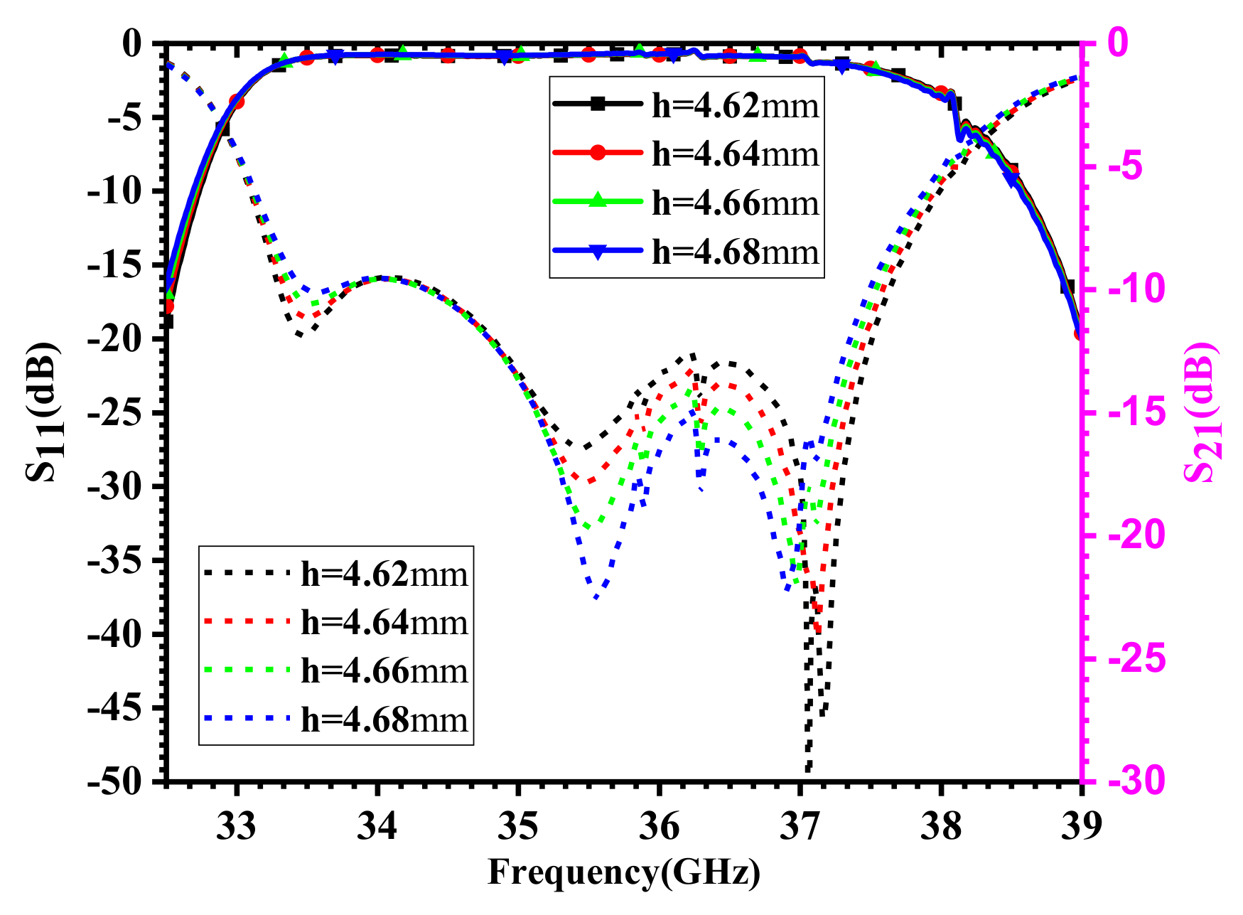
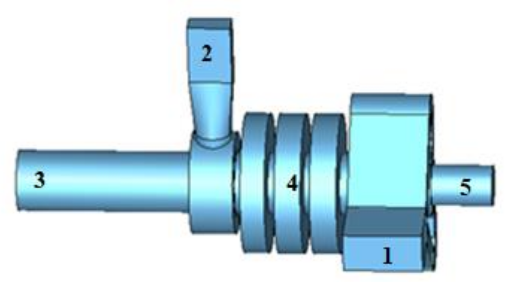
Based on the front studies, a dual-mode input coupler for K/Ka dual-band Gyro-TWT is designed, as shown in Figure 10. Port 1 is the input port for in the K-band, port 2 is the input port for in the Ka-band, port 3 is the output port with a radius of 5.1 mm, Section 4 is the Bragg reflector, and port 5 is the cut-off port. Figure 11 shows the electric field distribution of the input coupler when the operating mode is at a frequency of 18 GHz and the at a frequency of 34 GHz. It can be seen that the electric field is blocked in the Bragg reflector and no field is transmitting into the Y-type input coupler when the dual-mode input coupler is operating at, and the Bragg reflector has no influence on the transmission of . Figure 12 and Figure 13 plot the S-parameter and phase of the designed dual-mode input coupler in the K/Ka-band. It is shown that the reflection coefficient in the frequency range of 18.3~21 GHz is below −10 dB when the output mode is , the −1 dB bandwidth of transmission can reach 3.15 GHz. Meanwhile, the reflection coefficient in the frequency range of 33.7~37.2GHz is below −10 dB when the output mode is , and the −1 dB bandwidth is 3.32 GHz. The comparison between the presented input coupler and that in [19] is shown in Table 2. It can be seen that the input coupler bandwidth is relatively broadened to wide. The designed input coupler can be used as a dual-band large bandwidth Gyro-TWT.
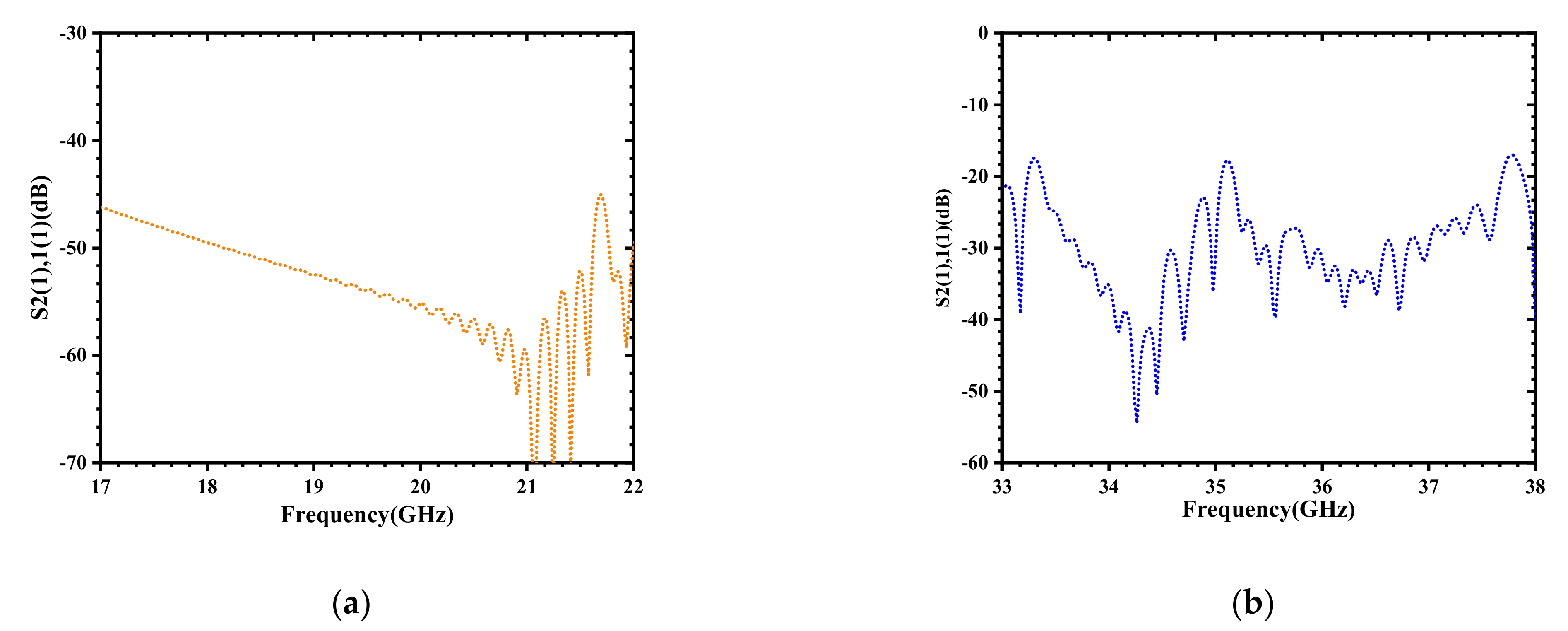
Figure 14 plots the isolation between the two input rectangular waveguides when the designed dual-mode input coupler is operating at K-band and Ka-band, respectively. When the coupler is operating in the K-band, the isolation of the mode is below −40 dB in the 17~22GHz frequency range. When operating in the Ka-band, the isolation of the mode is below −20 dB in the frequency range of 33~38 GHz. Through these analyses, it is proved that the designed input coupler has good properties for single-mode operating.
4. Conclusions
Dual-band Gyro-TWTs can be used in new radars, communication systems and other fields to achieve cross-band operation requirements. In this paper, a Gyro-TWT input coupler for dual-band operation is presented. The coupler realizes the transition from the rectangular waveguide mode to the circular waveguide mode in different wavebands. The designed structure is composed of two different types of input couplers, one is the coaxial input coupler for the Ka-band Gyro-TWT and the other is a Y-type input coupler for the K-band Gyro-TWT. For reducing the reflection wave from reflecting into the Y-type input coupler to influence the operating bandwidth, a Bragg reflector is inserted to connect these two couplers. Through optimization, the −1 dB bandwidth of the dual-band input coupler can achieve 3.15 GHz in the K-band with the output mode of and 3.32 GHz in the Ka-band with the output mode of . Meanwhile, the isolation degree of the two input rectangular ports is below −20 dB. The designed dual-mode input coupler can be well used for dual-band Gyro-TWTs.
Author Contributions
Conceptualization, M.M. and Q.Z.; methodology, M.M., L.P.; resources, S.Z., K.M., Y.L. and J.F.; data curation, Q.Z.; formal analysis, Q.Z., J.F.; writing—original draft preparation, M.M. and Q.Z.; writing—review and editing, Q.Z., J.F.; funding acquisition, Q.Z., J.F. All authors have read and agreed to the published version of the manuscript.
Funding
This research was funded by the National Natural Science Foundation of China: 62001131, the Dean Project of Guangxi Key Laboratory of Wireless Broadband Communication and Signal Processing Grant Nos: GXKL06190102, the Guangxi Natural Science Foundation Project: 2019GXNSFBA245066, and the Guangxi Science and Technology Base and Talent Special Project: AD19245042.
Conflicts of Interest
The authors declare no conflict of interest.
References
- Chu, K.R.; Lin, A.T. Gain and bandwidth of the Gyro-TWT and CARM amplifiers. IEEE Trans. Plasma Sci. 1988, 16, 90–104. [Google Scholar] [CrossRef]
- Li, H.H.; Wang, K.S.; Zhao, J.X.; Xiao-xin, L.I.A.N.G.; Yue-peng, Y.A.N. A design of Ka-band power amplifier based on 0. 15 μm GaAs pHEMT process. Microelectron. Comput. 2021, 38, 17–21. [Google Scholar]
- Hosseinzadeh, N.; Medi, A. Wideband 5 W Ka-Band GaAs Power Amplifier. IEEE Microw. Wirel. Compon. Lett. 2016, 26, 1–3. [Google Scholar] [CrossRef]
- Chu, K.R. Overview of Research on the gyrotron traveling-wave amplifier. IEEE Trans Plasma Sci. 2002, 30, 903–908. [Google Scholar]
- Baik, C.-W.; Jeon, S.-G.; Kim, D.-H.; Sato, N.; Yokoo, K.; Park, G.-S. Third-harmonic frequency multiplication of a two-stage tapered gyrotron TWT amplifier. IEEE Trans. Electron Devices 2005, 52, 829–838. [Google Scholar] [CrossRef]
- Linde, G.J.; Ngo, M.T.; Danly, B.G.; Cheung, W.J.; Gregers-Hansen, V. WARLOC: A high-power coherent 94 GHz radar. IEEE Trans. Aerosp. Electron. Syst. 2008, 44, 1102–1117. [Google Scholar] [CrossRef]
- Paoloni, C.; Gamzina, D.; Letizia, R.; Zheng, Y.; Luhmann, N.C., Jr. Millimeter wave traveling wave tubes for the 21st Century. J. Electromagn. Waves Appl. 2021, 35, 567–603. [Google Scholar] [CrossRef]
- Chu, K.R.; Chen, H.Y.; Hung, C.L.; Chang, T.-H.; Barnett, L.; Chen, S.-H.; Yang, T.-T.; Dialetis, D.J. Theory and experiment of ultrahigh-gain gyrotron traveling wave amplifier. IEEE Trans. Plasma Sci. 1999, 27, 391–404. [Google Scholar]
- Yan, R.; Luo, Y.; Liu, G.; Pu, Y. Design and experiment of a Q-band gyro-TWT loaded with lossy dielectric. IEEE Trans. Electron. Devices 2012, 59, 3612–3617. [Google Scholar] [CrossRef]
- Samsonov, S.V.; Gachev, I.G.; Denisov, G.G.; Bogdashov, A.; Mishakin, S.V.; Fiks, A.S.; Soluyanova, E.A.; Tai, E.M.; Dominyuk, Y.V.; Levitan, B.A.; et al. Ka-Band gyrotron traveling-wave tubes with the highest continuous-wave and average power. IEEE Trans. Electron. Devices 2014, 61, 4264–4267. [Google Scholar] [CrossRef]
- Harriet, S.B.; McDermott, D.B.; Gallagher, D.A.; Luhmann, N. Cusp Gun TE21 Second-Harmonic Ka-Band Gyro-TWT Amplifier. IEEE Trans. Plasma Sci. 2002, 30, 909–914. [Google Scholar] [CrossRef]
- He, W.; Donaldson, C.R.; Zhang, L.; Ronald, K.; Phelps, A.D.R.; Cross, A.W. Broadband amplification of low terahertz signals using axis-encircling electrons in a helically corrugated interaction region. Phys. Rev. Letts. 2017, 119, 184801. [Google Scholar] [CrossRef] [PubMed] [Green Version]
- Xu, Y.; Xiong, C.D.; Yong, L.; Jianxun, W.; Ran, Y.; Youlei, P.; Wang, H.; Li, H. Design of broad-band input coupler of Ka-band TE01 mode gyro-TWT. Chin. J. Vac. Sci. Technol. 2012, 32, 208–213. [Google Scholar]
- Xiong, W.J.; Wang, L.; Luo, Y.; Guo, L. Improved design of input and output structures of W band gyro-TWT. High Power Laser Part. Beams 2013, 25, 693–698. [Google Scholar] [CrossRef]
- Wang, Q.S.; Huey, H.E.; McDermott, D.B.; Hirata, Y.; Luhmann, N. Design of a W-band Second-harmonic TE02 gyro-TWT amplifier. IEEE Trans. Plasma Sci. 2000, 28, 2232–2238. [Google Scholar] [CrossRef]
- McDermott, D.B.; Song, H.H.; Hirata, Y.; Lin, A.T.; Barnett, L.R.; Chang, T.H.; Hsu, H.-L.; Marandos, P.S.; Lee, J.; Chu, K.R.; et al. Design of a W-band TE 01 mode gyrotron traveling-wave amplifier with high power and broad-band capabilities. IEEE Trans. Plasma Sci. 2003, 30, 894–902. [Google Scholar] [CrossRef] [Green Version]
- Liu, G. Input coupler design for Ka band gyrotron TWT. In Proceedings of the 2016 IEEE International Vacuum Electronics Conference (IVEC), Monterey, CA, USA, 19–21 April 2016; pp. 1–2. [Google Scholar]
- Zhang, L.; He, W.; Donaldson, C.; Garner, J.R.; McElhinney, P.; Cross, A.W. Design and Measurement of a Broadband Sidewall Coupler for a W-Band Gyro-TWA. IEEE Trans. Microw. Theory Tech. 2015, 63, 3183–3190. [Google Scholar] [CrossRef] [Green Version]
- Sun, M. Research on the Transmission Link of Gyro-TWT Input and Output System [D]; University of Electronic Science and Technology of China: Chengdu, China, 2019; pp. 34–65. [Google Scholar]
- Xu, Y.; Li, Y.; Wang, J.X.; Jiang, W.; Liu, G.; Luo, Y.; Li, H. Design and experiment of a high power and broadband Ku-Band TE11 mode Gyro-TWT. IEEE Trans. Electron. Devices 2018, 66, 1559–1566. [Google Scholar] [CrossRef]
- Yu, C.F.; Chang, T.H. High-performance circular TE01-mode converter. IEEE Trans. Microw. Theory Tech. 2005, 53, 3794–3798. [Google Scholar]
- Collin, R.E. Field Theory of Guided Waves; Wiley Interscience: New York, NY, USA, 1990; pp. 415–420. [Google Scholar]
- Chong, C.K.; McDermott, D.B.; Razeghi, M.M.; Luhmann, N.C.; Pretterebner, J.; Wagner, D.; Thumm, M.; Caplan, M.; Kulke, B. Bragg reflectors. IEEE Trans. Plasma Sci. 1992, 20, 393–402. [Google Scholar] [CrossRef]
- Peskov, N.Y.; Ginzburg, N.S.; Kaminskii, A.A.; Kaminskii, A.K.; Sedykh, S.N.; Sergeev, A.P.; Sergeev, A.S. High-efficiency narrow-band free-electron maser using a Bragg cavity with a phase discontinuity in the ripples. Tech. Phys. Lett. 1999, 25, 429–432. [Google Scholar] [CrossRef]
- Emile, D.R. Innovative corrugated transmission line for Terahertz wave-guiding. In Proceedings of the 2011 International Conference on Infrared, Millimeter, and Terahertz Waves, Houston, TX, USA, 2–7 October 2011; pp. 1–2. [Google Scholar]
- Wenzel, H.; Guther, R.; Shams-Zadeh-Amiri, A.M.; Bienstman, P. A comparative study of higher order Bragg gratings: Coupled-mode theory versus mode expansion modeling. IEEE J. Quantum Electron. 2006, 42, 64–70. [Google Scholar] [CrossRef]
Figure 1.
Schematic diagram of the coaxial input coupler.

Figure 2.
The relationship between the Eigenvalue root and the inner coaxial cavity and outer coaxial cavity radii ratio .
Figure 2.
The relationship between the Eigenvalue root and the inner coaxial cavity and outer coaxial cavity radii ratio .

Figure 3.
Coupler structure and field distribution diagram.

Figure 4.
The influence of the coupling rectangle gap width on transmission and reflection of the input coupler.
Figure 4.
The influence of the coupling rectangle gap width on transmission and reflection of the input coupler.

Figure 5.
The influence of the coupling rectangle gap length on transmission and reflection of the input coupler.
Figure 5.
The influence of the coupling rectangle gap length on transmission and reflection of the input coupler.

Figure 6.
Geometric structure of the Y-type input coupler.

Figure 7.
Simulation results of the Y-type input coupler.

Figure 8.
Structure diagram of the Bragg reflector.

Figure 9.
(a) Reflection amplitude (the black-dot curve) and phase (the blue-dot curve) of of mode, (b) the reflection and transmission of mode.
Figure 9.
(a) Reflection amplitude (the black-dot curve) and phase (the blue-dot curve) of of mode, (b) the reflection and transmission of mode.

Figure 10.
Structure diagram of dual-frequency input coupler (1 is the input port for in K-band, 2 is the input port for in Ka-band, 3 is the output port, 4 is the Bragg reflector, 5 is the cut-off port).
Figure 10.
Structure diagram of dual-frequency input coupler (1 is the input port for in K-band, 2 is the input port for in Ka-band, 3 is the output port, 4 is the Bragg reflector, 5 is the cut-off port).

Figure 11.
The electric field diagram of input coupler, (a) the output mode is , (b) the output mode is .
Figure 11.
The electric field diagram of input coupler, (a) the output mode is , (b) the output mode is .

Figure 12.
The S-parameter for the designed dual-mode input coupler, (a) the S-parameter when the output mode is , (b) the S-parameter when the output mode is .
Figure 12.
The S-parameter for the designed dual-mode input coupler, (a) the S-parameter when the output mode is , (b) the S-parameter when the output mode is .

Figure 13.
The phase of S21 for the designed dual-mode input coupler, (a) the phase of when the output mode is , (b) the phase of when the output mode is .
Figure 13.
The phase of S21 for the designed dual-mode input coupler, (a) the phase of when the output mode is , (b) the phase of when the output mode is .

Figure 14.
The isolation between the input rectangular (a) port 1 and (b) port 2 (ports 1 and 2 are labeled in Figure 10).
Figure 14.
The isolation between the input rectangular (a) port 1 and (b) port 2 (ports 1 and 2 are labeled in Figure 10).


Table 1.
Dimensions of the Bragg reflector.
| Section Number | Length (mm) |
|---|---|
| 1 | 3 |
| 2 | 4 |
| 3 | 1.6 |
| 4 | 4.3 |
| 5 | 1.5 |
| 6 | 4.3 |
| 7 | 2 |
Table 2.
The dual-band input coupler parameters.
| Parameters | This Article | Reference [19] |
|---|---|---|
| Operating Frequency | 19/34GHz | 17/33GHz |
| Operating Mode | - @ Ka-band and -@ K-band | - @ Ka-band and -@ K-band |
| −1 dB Bandwidth | 3.15 GHz @ K-band,3.32 GHz@ Ka-band | 1.9 GHz @ K-band, 2 GHz@ Ka-band |
Publisher’s Note: MDPI stays neutral with regard to jurisdictional claims in published maps and institutional affiliations. |
© 2022 by the authors. Licensee MDPI, Basel, Switzerland. This article is an open access article distributed under the terms and conditions of the Creative Commons Attribution (CC BY) license (https://creativecommons.org/licenses/by/4.0/).
Share and Cite
MDPI and ACS Style
Ma, M.; Zhao, Q.; Mo, K.; Zheng, S.; Peng, L.; Lv, Y.; Feng, J. Design of a Dual-Mode Input Structure for K/Ka-Band Gyrotron TWT. Electronics 2022, 11, 432. https://doi.org/10.3390/electronics11030432
AMA Style
Ma M, Zhao Q, Mo K, Zheng S, Peng L, Lv Y, Feng J. Design of a Dual-Mode Input Structure for K/Ka-Band Gyrotron TWT. Electronics. 2022; 11(3):432. https://doi.org/10.3390/electronics11030432
Chicago/Turabian StyleMa, Mengshi, Qixiang Zhao, Kunshan Mo, Shuquan Zheng, Lin Peng, You Lv, and Jinjun Feng. 2022. "Design of a Dual-Mode Input Structure for K/Ka-Band Gyrotron TWT" Electronics 11, no. 3: 432. https://doi.org/10.3390/electronics11030432
Note that from the first issue of 2016, this journal uses article numbers instead of page numbers. See further details here.