Verification of the Performance of a Vertical Ground Heat Exchanger Applied to a Test House in Melbourne, Australia


Faculty of Architecture, Building and Planning, Melbourne School of Design, The University of Melbourne, Buildings 133, Parkville, VIC 3010, Australia
*
Author to whom correspondence should be addressed.
Energies 2017, 10(10), 1558; https://doi.org/10.3390/en10101558
Submission received: 29 August 2017
/
Revised: 2 October 2017
/
Accepted: 7 October 2017
/
Published: 10 October 2017
(This article belongs to the Special Issue Selected Papers from ZEMCH 2016: Building Energy Performance Evaluation/Simulation)
Abstract
:The ground heat exchanger is traditionally used as a heat source or sink for the heat pump that raises the temperature of water to about 50 °C to heat houses. However, in winter, the heating thermostat (temperature at which heating begins) in the Australian Nationwide House Energy Rating Scheme (NatHERS) is only 20 °C during daytime and 15 °C at night. In South-East Melbourne, the temperature at the bottom of a 50-m-deep borehole has been recorded with an Emerson™ recorder at 17 °C. Melbourne has an annual average temperature of 15 °C, so the ground temperature increases by 2 °C per 50-m depth. A linear projection gives 23 °C at 200-m of depth, and as the average undisturbed temperature of the ground for a 400-m-deep vertical ground heat exchanger (VGHE). This study, by simulation and experimentation, aims to verify that the circulation of water in the VGHE’s U-tube to low-temperature radiators (LTRs) could heat a house to thermal comfort. A literature review is included in the introduction. A simulation, using a model of a 60-m2 experimental house, shows that the daytime circulation of water in this VGHE/LTR-on-opposite-walls system during the 8-month cold half of the year, heats the indoors to NatHERS settings. Simulation for the cold half shows that this VGHE-LTR system could cool the indoors. Instead, a fan creating a cooling sensation of up to 4 °C is used so that the VGHE is available for the regeneration of heat extracted from the ground during the cold portion. Simulations for this hot portion show that a 3.4-m2 flat plate solar collector can collect more than twice the heat extracted from the ground in the cold portion. Thus, it can thus replenish the ground heat extracted for houses double the size of this 60-m2 experimental house. Therefore, ground heat is sustainable for family-size homes. Since no heat pump is used, the cost of VGHE-LTR systems could be comparable to systems using the ground source heat pump. Water circulation pumps and fans require low power that can be supplied by photovoltaic thermal (PVT). The EnergyPlus™ v8.7 object modeling the PVT requires user-defined efficiencies, so a PVT will be tested in the experimental house.
1. Introduction
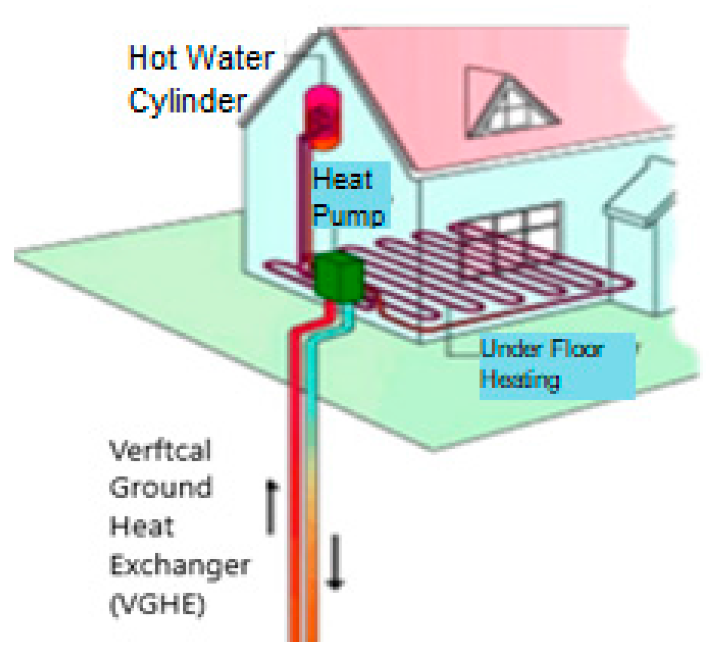
Traditionally, the vertical ground heat exchanger (VGHE) shown in Figure 1 serves only as a heat source or sink for the heat pump, which raises water temperature to about 50 °C for underfloor heating. But in winter, the heating thermostat during the day is 20 °C for the living area, and 15 °C during the night for the bedroom. (Australian Nationwide House Energy Rating Scheme, NatHERS [1]). This research aims to verify that circulating water in the U-tube of a VGHE surrounded by 23 °C ground-to-low temperature radiator (LTR) can heat houses to NatHERS settings. This VGHE-LTR system is used in scaled-down family-size experimental houses that are modelled for simulation using the US Department of Energy’s EnergyPlus™ v8.7 software (www.energyplus.net) [2].
Melbourne has an annual average temperature of 15 °C. In a southeastern suburb of Melbourne, Australia, a thermistor at the bottom of the U-tube of a 50-m-deep VGHE and an Emerson™ recorder measured the temperature as 17 °C. This gives a ground temperature increase of 2 °C per 50-m depth, which is on the higher side of the International Panel on Climate Change’s data of 25–30 °C increase per kilometer depth [3]. Simulations using a model of this site’s 30-m2 house with circulation of water from this VGHE to floor-LTR, and circulation of water in a 2-m3 indoor tank, heated by 30 evacuated tubes to 50 °C by the end of summer to wall-LTRs, showed that these two heated waters could make the indoors thermally comfortable [4].
Simulations use the US Department of Energy’s EnergyPlus™ v8.7 software [2]. The VGHE is modelled by the GroundHeatExchanger:Vertical object (object names cannot have spaces). Eskilson developed nondimensional temperature response factors (called g-functions) to estimate the temperature of ground-loop heat exchangers [5]. The long-time and short-time g-functions of boreholes were respectively studied by Eskilson and Yavuzturk, and Spitler [5,6] Murugappan developed the variable, short-time step model that accommodates subhourly responses, variable time steps and explicit equations to calculate the outlet fluid temperature of the ground loop heat exchanger [7]. Section 2, Materials and Methods, Table 3 shows the fields of this object with footnotes explaining the VGHE depth and ground temperature in more detail. The LowTemperatureRadiant:VariableFlow object is used to model the LTR. The simulated results using this object were validated by Chantrasrisalai et al. [8]. They concluded that “good agreements between predicted and experimental results can be achieved in the EnergyPlus low-temperature radiant simulation by adjusting appropriate input parameters that can have an impact on the systems”. Therefore, experimental houses would have adjustable insulation thicknesses and adjustable lengths of the water tubing of the LTRs. This object can output either only heating energy or only cooling energy, so simulations for the cold and hot halves of the year are run separately. Trancossi et al. presented guidelines of a wall with water inside with the objective of maximizing the performances of the wall for reaching optimal internal wellness conditions. “If circulating water is thermally stabilized by exchanging in the ground such as it happens in geothermal plants, a thermal shield could be realized keeping walls in comfort conditions and minimizing energy needs for further temperature regulations” [9].
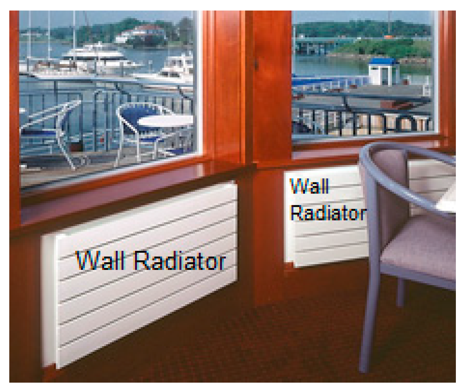
Modern house envelopes have high insulations. Highly-insulated walls and roofs reduce heat transfer rates with the outdoors. Figure 2 illustrates that the body of seated occupants have a larger view factor for radiative heat transfer with wall-LTRs than with the conventional floor radiators. These assist wall-LTRs in keeping occupants thermally comfortable. Thus, in models for simulation, LTRs are placed on opposite long walls [10].
Simulations also verify that during the hot portion of the year, this 23 °C ground VGHE could cool the LTRs and indoors. However, it is recommended to use fans that can make up to 31 °C indoors comfortable [11]. This frees the VGHE to regenerate ground heat by the circulation of solar-heated water to its U-tube. If solar-heated water can transfer sufficient heat to replenish that extracted from the ground, the VGHE becomes a sustainable device. How to use water heated by the sun to buffer the winter cold (inter-seasonal storage) had been studied since 1995 [12,13,14]. For small residential buildings, the ground could be used for interseasonal storage. “The loss of heat is acceptable if the ground storage is cuboidal shape and must be heat-insulated and damp-proof.” This implies that after two decades of research, storing summer heat for winter is still problematic [14]. Hydronic heating sellers had used 5 m3 of water storage for Melbourne, and many of these systems were struggling to provide 2 h of effective heat. Simulations using the 2-m3 indoor tank to contain water heated by 30-evacuated tube solar collector to assist in heating the 30 m2 house to thermal comfort show that the water temperature is only 20 °C by the end of winter [4]. Therefore, the size of the indoor tank could be too large for a family-size house. The above problems with inter-easonal storage could be solved by the VGHE. The ground below 15 m is not affected by the extreme outdoor temperature and is thus a stable temperature heat source. The heat capacity of rock is about portion that of the 4184 J/(kg·K) of water, and the thermal capacitance of the ground increases as the depth is increased; hence, there is a good heat store a few hundred meters deep in the ground.
2. Materials and Method
Verification of the performance of this VGHE-LTR system is by simulation with a 60-m2 house. This rather large experimental house is used so that heat can be projected, by proportion, to find the heat required for family-size (about 144 m2) houses.
2.1. The 60-m2 Experimental House
Melbourne is where “star-rated homes require heating” [15]. In 2007, the state of Victoria, of which Melbourne is the capital city, accounts for a 59% share of the national space heating energy consumption [16]. Therefore, it is logical to have experimental houses in Melbourne.
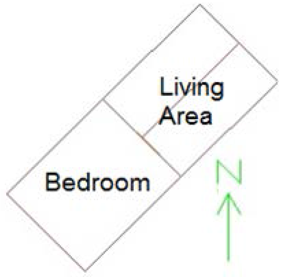
The 50-m-deep, 17 °C bottom temperature VGHE was installed next to a 30-m2 insulated experimental house in South-East Melbourne [4]. The 6 m walls face northwest and southeast. Simulations in this study use a model of this 30-m2 zoned as the living area of a 60-m2 house shown in Figure 3. The future experimental house is proposed to be with a VGHE surrounded by ground with an average temperature of 23 °C. The site is in another southeastern Melbourne suburb and the depth of the VGHE is estimated at 400 m.
With insulations for the 30-m2 living area shown in Table 1 and 100 mm, 150 mm and 200 mm-thick structural insulated panels (SIPs) at the floor, wall and roof respectively for the 30-m2 bedroom extension, this 60-m2 house is rated at the mandatory six stars by the Australian FirstRate5 house energy rating software [17]. The floor is damp-proofed with a layer of ‘builders plastic’ sheet.
2.2. Temperatures Beneath (on the Outside Face of) the Floor
The EnergyPlus website provides hourly representative meteorological weather data of the outdoor conditions for the computation of the dynamic heat flow through the walls and roofs [2]. The outside temperature of the floor is found from EnergyPlus 3-D ‘Slab’ preprocessor based on monthly averaged indoor temperatures. Since the LTRs are expected to make indoors thermally comfortable during the cold months, the weighted average of NatHERS heating thermostats of 18.35 °C are used for June to September. Slab simulations based on a soil thermal diffusivity of 2.3225760 × 10⁻³ m2/day show that the temperatures beneath the floor converged after eight years and Table 2 shows the monthly averaged temperatures beneath the floor. The minimum, from June to August, is about 16.55 °C, or about 2 °C lower than the conditioned indoor temperatures. This is verified by EnergyPlus documentation which states that 2 °C lower than indoor temperatures can be used as approximate values [2].
2.3. Modelling the Ground Heat Exchanger:Vertical (VGHE) Plant, Low Temperature Radiators (LTRs) and Water Loops
2.3.1. VGHE Modelled by EnergyPlus’s GroundHeatExchanger:Vertical Object
EnergyPlus’s GroundHeatExchanger:Vertical object (object names cannot have spaces) is used to model the VGHE. Table 3 shows the field names, entries and notes. During the installation of the 50-m-deep VGHE, the soil is sand that transitions to hard siltstone below between 8–20 m. The ground thermal conductivity of 1.98 W/(m·K) is for siltstone. After insertion of the U-tube, the borehole was filled with grout of 1.98 W/(m·K) thermal conductivity. In a single simulation run, this object can compute for both positive and negative heat transfers at the VGHE [2].
2.3.2. LTR Modelled by EnergyPlus’s LowTemperatureRadiant:VariableFlow Object
The LTR is modelled by Energy’s LowTemperatureRadiant:VariableFlow object. In a single simulation run, this object can compute either only heating energy or only cooling energy. So, simulation runs for the cold and hot portions of the year are done separately. The entries in Table 4 are for the LTRs on opposite walls of the living area, used for heating for the eight-month cold portion of the year from 22 March to 21 November. When simulation is run for the hot portion of the year (22 November to 21 March), entries are made to the ‘Cooling’ fields (not shown but stated in the notes). Simulation then outputs the only the cooling rates and energy.
2.3.3. Water Loops in the VGHE-LTR System
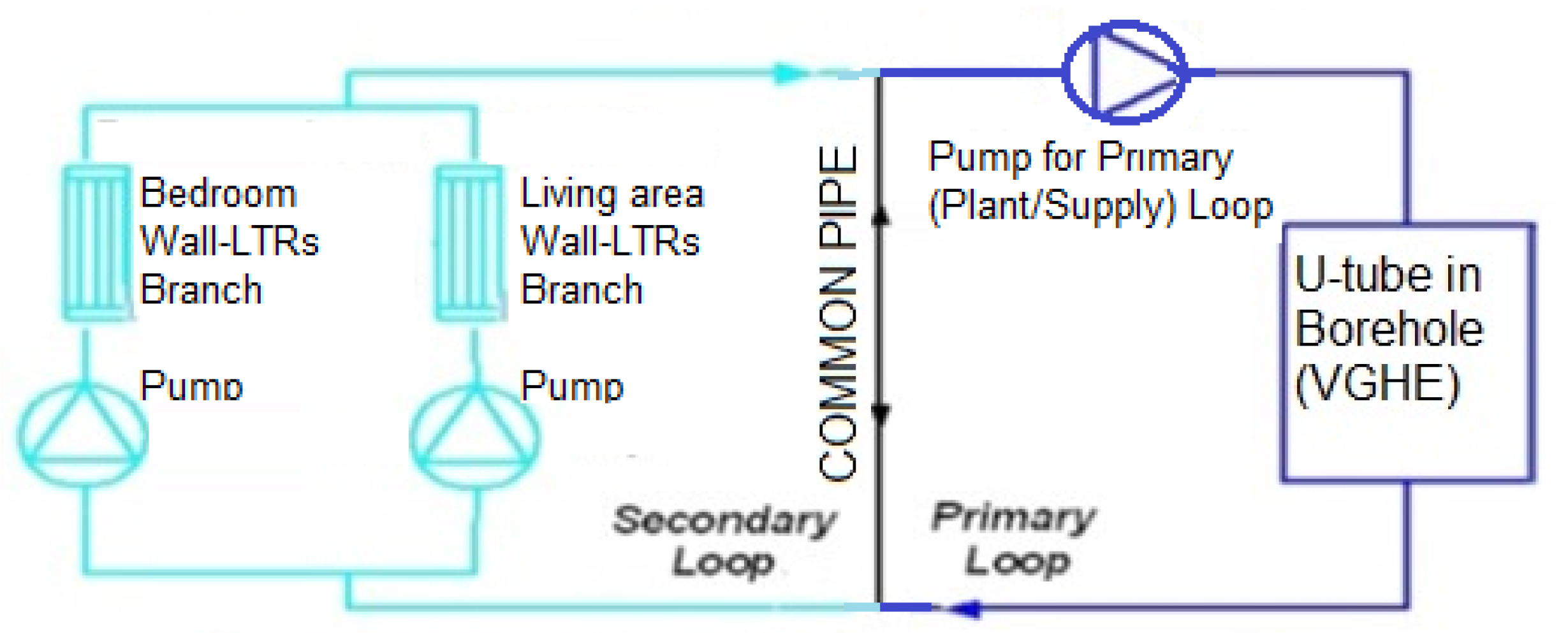
Figure 4 shows the VGHE as a primary loop and the separate LTRs for the bedroom and living area as branches of a secondary loop. The common pipe serves to buffer any differences in the water flow rates or temperatures between the primary and secondary loops.
3. Simulated Results
3.1. Heating Run for the Cold Portion (22 March to 21 November) of the Year
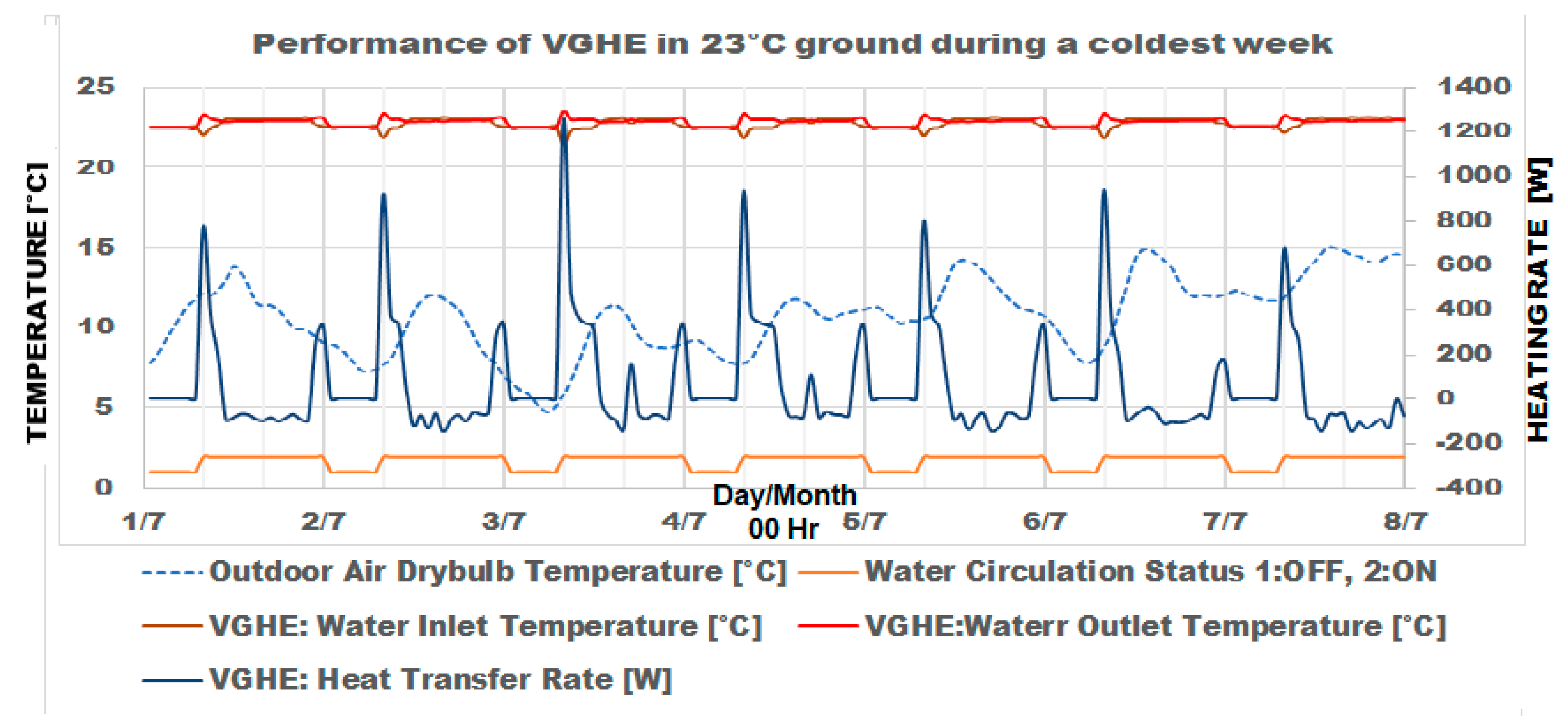
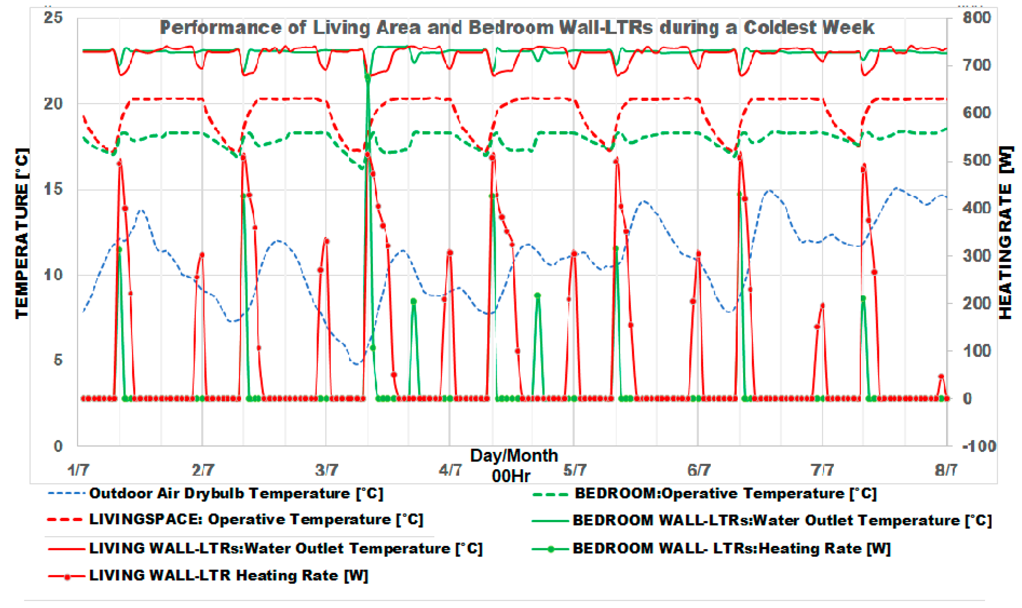
Figure 5 and Figure 6 show the respective simulated results for the VGHE and the LTRs for the coldest week (1 July to 7 July). The temperatures (°C) are indicated on the left axis and the heat transfer rates (W) are indicated on the right axis.
The inlet and outlet water temperatures of the VGHE are shown by green and brown lines at the top of Figure 5. The differences are discernable at 7 a.m., when the heating thermostats for living area and bedroom are increased by 3 °C and there are spikes in the heat transfer (dark blue lines) after 7 a.m. The light blue line at the bottom shows that the pumps are stopped from midnight to 7 a.m. For the afternoons when the inlet water is hotter than the outlet water, heating rates are negative. For the eight-month cold portion of the year, the VGHE supplies a net of 127,064 Wh heat from the ground to the LTRs.
Figure 6 shows that during the day, the living area wall-LTRs heat the living area to NatHERS heating thermostat of 20 °C. The bedroom wall-LTRs heat the bedroom to NatHERS heating thermostats of 18 °C from 7 a.m. to 9 a.m. and from 4 p.m. to midnight. These are set back to 15 °C at other times and causes the spikes in the heating rates at the 3 °C step-ups. From midnight to 7 a.m., the NatHERS heating thermostat for the bedroom is also 15 °C. In simulation, the set point for the living are is also set back to 17 °C.
3.2. Cooling Run for the Hot Portion (22 November to 21 March) of the Year
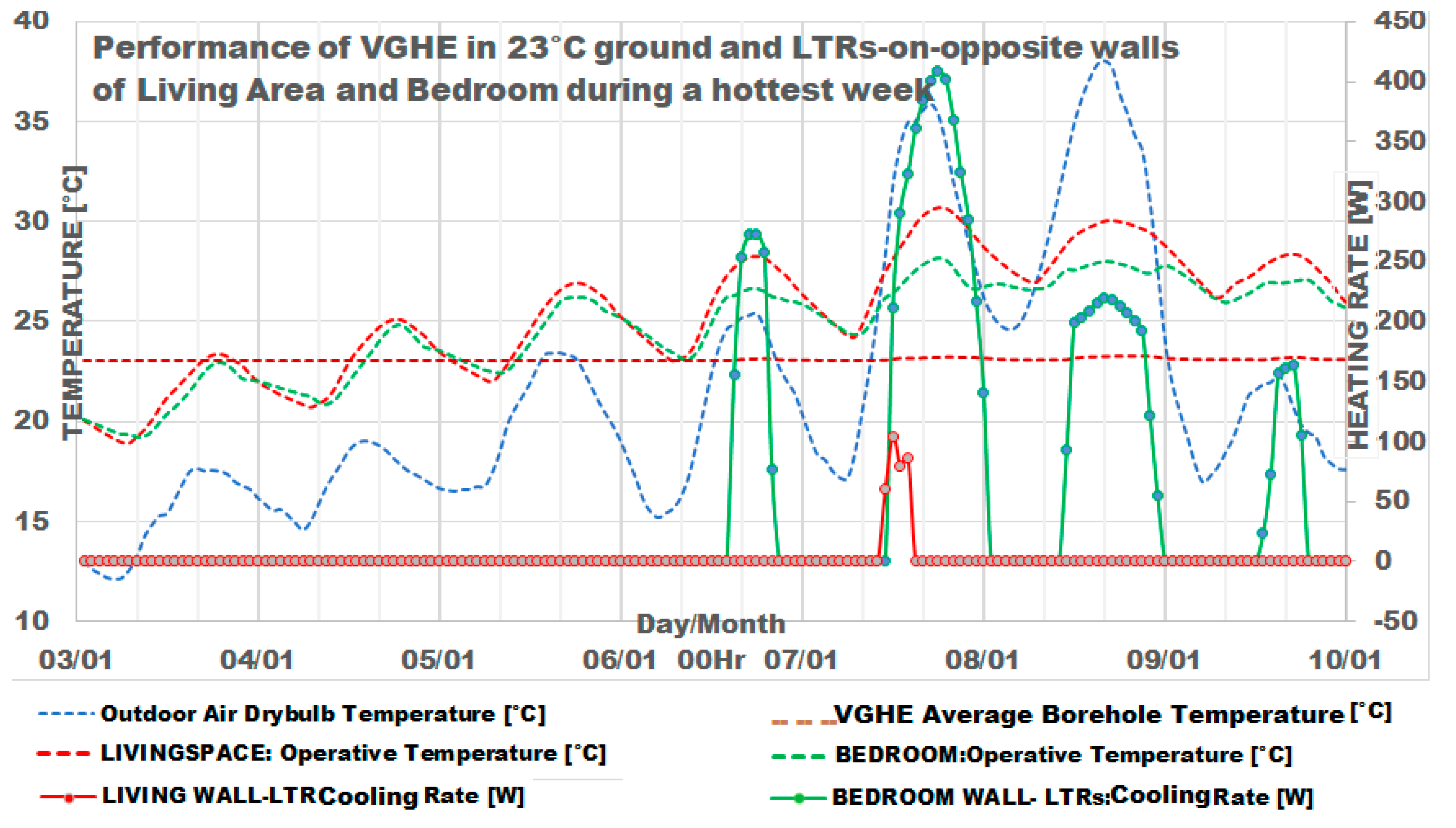
Figure 7 shows that only for one day in the hottest week (3–9 January), the temperature of the simulated living area is above 26.5 °C. This is the temperature (cooling thermostat of 24 °C for Melbourne climatic zone plus 2.5 °C) at which NatHERS starts to calculate cooling energy in its star rating of houses in Melbourne’s climate zone. Figure 8 also shows that the outdoor temperature is above 32 °C only for 2 days. Instead, fans that can create a cooling sensation of up to 4 °C are recommended. This will free the VGHE to regenerate the heat extracted from the ground during the cold portion.
The design load for the bedroom and living area are based on an outdoor temperature of 31.9 °C, which will be exceeded only for 1% of the time in a year. Table 5 shows that the total design load is about 1.2 kW, a fair figure for this 60-m2 insulated house. Table 5 also shows that for the eight-month cold portion of the year, the simulated heat extracted from the ground (which can be positive or negative) is 127,064 W, and the simulated heat supplied by both LTRs, which is only positive, is 346,685 Wh. Simulations for the four-month hot portion of the year show that a 3.3937-m2 gross-area Beijing Sunda Solar Energy Technology Co. Ltd., SEIDO 10-20ASAB (Beijing, China) can collect 702 kWh of solar heat. This is double that supplied by the LTRs for this 60-m2 house. Therefore, heat supplied from the ground for family-sized (about 150 m2) homes can be sustainable.
Table 5 shows that the simulated power to circulate water through the VGHE is 39.3 W and that to circulate water through the 400 m of 13-mm-diameter tubing of the LTRs is 4 W. This 44 W total is validated when a 25 W fish tank pump circulated water from the U-tube of the 50-m-deep VGHE to a 75-m-long tubing of a floor-LTR [19].
4. Discussion
4.1. Operation of VGHE with and without Ground Source Heat Pump (GSHP)
The ground heat exchanger operates better with a constant load than with cyclic loads with large variations in the heating load to keep its temperature rise restrained within a certain limit [20]. In Melbourne, Australia, many GSHP operate only intermittently and simulated results in this paper have shown that GSHP may be obviated. Without the intermittent operation of the GSHP, the VGHE-LTR system the operation of GHE could thus be improved. Therefore, simulation and experimentation should proceed.
4.2. PVT to Be Tested in VGHE-LTR Heated Experimental House
Low power is required to operate water pumps plus the cooling fans in summer, or the fan(s) to draw outdoor air that cools the PVT into the house as preheated ventilation air in winter. A 300-W solar photovoltaic will be tested in the experimental house for the user-defined efficiencies required as inputs for the EnergyPlus simulation.
4.3. Applicability of VGHE Heated Houses for Cold i.e., Annual Average Around 0 °C Places
The simulations using Melbourne’s weather data are run without water circulation from midnight to 7 a.m. Modern houses are well insulated, so this VGHE-LTR system could be applied to colder places indicated in Figure 8, but the water pumps may need to run continuously.
Based on the International Panel on Climate Change’s estimate of a 25–30 °C increase per kilometer depth, a VGHE less than two-kilometers deep could be surrounded by 23 °C ground [5]. Many VGHE installations are arranged in rectangular grids with a spacing of about 6 m between them, and the literature shows a good deal of research on the use of multiple VGHEs. To make ground heat sustainable, while one or a few are used to heat the indoors, the others are free for regeneration by solar-heated water.
5. Conclusions
EnergyPlus™ simulations verify that daytime circulation of water in the U-tube of a VGHE surrounded by 23 °C ground to low temperature radiators on opposite walls could make a 60-m2 Melbourne house thermally comfortable in winter. The system heated the house to the level that the Australian Nationwide House Energy Rating Scheme expects. During the hot half of the year, fans are used for comfort and ground heat can be replenished by circulating solar-heated water to the VGHE. Nonetheless, this study was carried out using a moderately sized 60-m2 house built in Melbourne even though majority of family homes in Melbourne are larger than this tested one. Accordingly, the effect of various housing sizes and the building envelope quality on the VGHE system performance need to be examined further.
Acknowledgments
The author would like to gratefully thank the following persons for emailing the information used in this paper. Michael O Connell, [email protected] Swinburne University of Technology, Australia who provided information on hydonic heating sellers in his email dated 2 May 2016. Donald Payne, [email protected], Direct Energy Australia who provided the soil conditions at and the grout thermal conductivity during the installation of the 50-m-deep VGHE in his email dated 27 August 2014.
Author Contributions
Koon Beng Ooi conceived the concept of VGHE-LTR and did the simulations. Masa Noguchi conceived the concept of PVT. Koon Beng Ooi proposed air-cooled PVT to provided preheated ventilation air in winter.
Conflicts of Interest
The authors declare no conflicts of interest.
References
- Nationwide House Energy Rating Scheme (NatHERS). ‘Australia’. 2016. Available online: http://www.nathers.gov.au/files/publications/NatHERS%20Software%20Accreditation%20Protocol-June%202012.pdf (accessed on 13 August 2016).
- US Department of Energy, EnergyPlus™ Building Simulation Software v8.7 2017 with Engineering Reference, InputOutput Reference and Weather Data. Available online: www.energyplus.net (accessed on 21 April 2017).
- Intergovernmental Panel on Climate Change (IPCC). IPCC Scoping Meeting on Renewable Energy Sources. 2008. Available online: https://www.ipcc.ch/pdf/supporting-material/proc-renewables-lubeck.pdf (accessed on 20 August 2016).
- Ooi, K.; Zou, W.X.P.; Abdullah, M.O. A Simulation Study of Passively Heated Residential Buildings. Procedia Eng. 2015, 121, 749–756. [Google Scholar] [CrossRef]
- Eskilson, P. Thermal Analysis of Heat Extraction Boreholes. Ph.D. Thesis, Department of Mathematical Physics, University of Lund, Lund, Sweden, 1987, unpublished. [Google Scholar]
- Yavuzturk, C.; Pitler, J.D. A Short Time Step Response Factor Model for Vertical Ground Loop Heat Exchangers. ASHRAE Trans. 1999, 105, 475–485. [Google Scholar]
- Murugappan, A. Implementing Ground Source Heat Pump and Ground Loop Heat Exchanger Models in the EnergyPlus Simulation Environment. Master’s Thesis, Department of Mechanical and Aerospace Engineering, Oklahoma State University, Stillwater, OK, USA, 2002. [Google Scholar]
- Chantrasrisalai, C.; Ghats, V.; Fisher, D.E.; Scheatzle, D.G. Experimental Validation of the EnergyPlus Low-Temperature Radiant Simulation. ASHRAE Trans. 2003, 109, 614–623. [Google Scholar]
- Trancossi, M.; Stewart, J.; Dumas, A.; Madonia, M.; Marques, J.P. Constructional Design of an Entropic Wall with Circulating Water Inside. J. Heat Transf. 2016, 138, 082801-1–082801-9. [Google Scholar] [CrossRef]
- Ooi, K.; Masa, N. A Simulation verification of Sustainable Geothermally-heated Home in Cool Climate. In Proceedings of the ZEMCH 2016 International Conference, Kuala Lumpur, Malaysia, 20–23 December 2016. [Google Scholar]
- Fountain, M.; Arens, E.A. Air Movement and Thermal Comfort. Available online: http://escholarship.org/uc/item/0q03g71s#page-3 (accessed on 14 August 2016).
- Oliveti, G.; Arcuri, N. Prototype Experimental Plant for the Inter Seasonal Storage of Solar Energy for the Winter Heating of Buildings: Description of Plant and Its Functions. Sol. Energy 1995, 54, 85–97. [Google Scholar] [CrossRef]
- Oliveti, G.; Arcuri, N.; Ruffolo, S. First Experimental Results from a Prototype Plant for the Inter Seasonal Storage of Solar Energy for the Winter Heating of Buildings. Sol. Energy 1998, 62, 281–290. [Google Scholar] [CrossRef]
- Kroll, J.A.; Ziegler, F. The Use of Ground Heat Storages and Evacuated Tube Solar Collectors for Meeting the Annual Heating Demand of Family-Sized Houses. Sol. Energy 2011, 85, 2611–2621. [Google Scholar] [CrossRef]
- Australian Government Department of Industry, Your Home: Australia’s Guide to Good Environmentally Sustainable Homes, 5th Edition. 2016. Available online: http://www.yourhome.gov.au/sites/prod.yourhome.gov.au/files/pdf/YOURHOME-PassiveDesign-DesignForClimate.pdf (accessed on 13 August 2016).
- Department of the Environment, Water, Heritage and the Arts (DEWHA). Commonwealth of Australia, Energy Use in the Australian Residential Sector 1986–2020. 2008. Available online: http://www.industry.gov.au/Energy/Energy-information/Documents/energyuseaustralianresidentialsector19862020part1.pdf (accessed on 29 November 2016).
- FirstRate5—House Energy Rating Software. Available online: https://www.fr5.com.au (accessed on 21 April 2017).
- Eppelbaum, L.; Kutasov, I.; Pilchin, A. Applied Geothermics; Springer: New York, NY, USA, 2014. [Google Scholar]
- Ooi, K.B.; Abdullah, M.O.; Noguchi, M. An Update of A simulated study of Passively heated residential buildings. GeoSci. Eng. 2016, 3, 12–17. [Google Scholar]
- Fang, Z.H.; Diao, N.R.; Cui, P. Discontinuous Operation of Geothermal Heat Exchangers. Tsinghua Sci. Technol. 2002, 7, 194–197. [Google Scholar]
Figure 1.
Vertical ground heat exchanger as sink for heat pump.

Figure 2.
Good view factor between wall radiators and body of occupant seated on chair.

Figure 3.
60-m2 experimental building—plan, orientation.

Figure 4.
Common pipe for VGHE (supply) loop and low-temperature radiators (LTR) branch (demand) loops.
Figure 4.
Common pipe for VGHE (supply) loop and low-temperature radiators (LTR) branch (demand) loops.

Figure 5.
VGHE pump operation, heating rates and water inlet/outlet temperatures for the coldest week.
Figure 5.
VGHE pump operation, heating rates and water inlet/outlet temperatures for the coldest week.

Figure 6.
Living area and bedroom temperatures and heating rates of LTRs in the coldest week.

Figure 7.
Indoor Temperatures with 23 °C far ground temperature, hottest week.

Figure 8.
Annual average temperature (°C) of places on earth.


Table 1.
Materials for the surfaces for the 60-m2 experimental house.
| Surface | Material | Thickness | Conductivity | Material R-Value | Surface R-Value |
|---|---|---|---|---|---|
| - | - | (mm) | W/(m·K) | m2·K/W | m2·K/W |
| Walls | - | - | - | - | 2.85 |
| (North-East & South-West) | F08 Metal | 0.08 | 45.28 | 0 | - |
| R3.5 Batt insulation | 110 | 0.04 | 2.75 | - | |
| G02 12 mm plywood | 12 | 0.12 | 0.1 | - | |
| Roof | - | - | - | 5.1 | |
| F08 Metal | 0.08 | 45.28 | 0 | - | |
| R5 Batt Insulation | 200 | 0.04 | 5 | - | |
| G02 12 mm plywood | 12 | 0.12 | 0.1 | - | |
| Floor | - | - | - | 2.7806 | |
| Concrete | 51 | 1.95 | 0.0262 | - | |
| Vapour-seal plastic film | - | - | 0.002 | - | |
| Polystyrene | 70 | 0.029 | 2.4138 | - | |
| G06 50 mm wood | 50.8 | 0.15 | 0.3387 | - | |
| LTR Walls | 0.1 m tube spacing | - | - | - | 4.1407 |
| (North-West & South-East) | R2.5 batt insulation | 110 | 0.04 | 2.75 | - |
| G04 13 mm wood | 12.7 | 0.15 | 0.0847 | - | |
| Expanded Polystyrene R12 | 25 | 0.02 | 1.25 | - | |
| Gypsum Plasterboard | 13 | - | 0.056 | - |
Table 2.
Monthly averaged indoor (heated in winter) and beneath floor temperatures (°C).
| Jan | Feb | Mar | Apr | May | Jun | Jul | Aug | Sep | Oct | Nov | Dec | |
|---|---|---|---|---|---|---|---|---|---|---|---|---|
| Indoor | 26.18 | 26.6 | 13.13 | 20.5 | 18.35 | 18.35 | 18.35 | 18.35 | 18.35 | 20.87 | 22.66 | 24.79 |
| Below Floor | 21.99 | 22.52 | 21.35 | 19.61 | 17.42 | 16.85 | 16.55 | 16.58 | 16.73 | 17.11 | 19.31 | 20.52 |
Table 3.
Data for EnergyPlus’s GroundHeatExchanger:Vertical object that models the VGHE.
| Name of Field | Entry | Notes |
|---|---|---|
| Number of Boreholes | 1 | One VGHE has one borehole |
| Design Flow Rate (L/s) | 0.16 | Autosized by earlier simulation |
| Borehole Length (m) | 400 | See footnote a |
| Borehole Radius (m) | 0.05 | Radius of 50 m borehole in SE Melbourne |
| Ground Thermal Conductivity (W/(m·K)) | 1.58 | Siltstone, below 8–20 m at 50 m borehole |
| Ground Thermal Heat Capacity (J/(m3·K)) | 2,218,500 | Eppelbaum et al. [18] |
| Ground Temperature (°C) | 23 | Undisturbed ’far field’ temperature b |
| Grout Thermal Conductivity (W/(m·K)) | 1.98 | Supplied by borehole installer |
| Pipe Thermal Conductivity (W/(m·K)) | 0.39 | High Density Polyethylene (HDPE) |
| Pipe Outer Diameter (m) | 0.02667 | Outer diameter of the tubes |
| U-Tube Distance (m) | 0.02539 | Distance between the two legs of U-tube |
| Pipe Thickness (mm) | 2.41 | c 35 pairs of non-dimensionalized time and g-functions are in the three Example Files downloadable from www.energyplus.gov |
| Maximum Length of Simulation (Years) | 2 | |
| g-Function Reference Ratio (dimensionless) | 0.0005 | |
| Number of Data Pairs of the g-function | 35 |
a Borehole Length of 400 m is based on an average ground temperature of 23 °C, at a half-depth of 200 m. This is based on the linear projection of 2 °C increase at 50 m of depth using the 17 °C measured at the bottom of the 50 m-deep U-tube in 15 °C annual average Melbourne; b ‘far field’ ground temperature is used in the analysis of the heat transfer with the VGHE assumed as a ‘line source’ borehole; c g-function reference ratio is the borehole radius divided by active length. This field is set to the default value of 0.0005. “EnergyPlus will adjust the g-functions internally to create the properly referenced g-function”. (EnergyPlus Input Output Reference [2]).
Table 4.
The LowTemperatureRadiant:VariableFlow object modelled for heating.
| Name of Field | Entry | Notes |
|---|---|---|
| Name | Living Wall Radiator | - |
| Availability Schedule Name | ColdMthsAvailSchedule | - |
| Zone Name | LivingSpace | Living area |
| Surface Name or Radiant Surface Group Name | LivingRadWalls | LTRs on opposite long walls |
| Hydronic Tubing Inside Diameter (m) | 0.013 | - |
| Hydronic Tubing Length (m) | autosize | - |
| Temperature Control Type | OperativeTemperature | These fields are used for simulation run for the cold portion of the year (22 March to 21 November). Separate fields (not shown) are used for simulation run for the cold portion (22 November to 21 March) of the year. |
| Heating Design Capacity Method | HeatingDesignCapacity | |
| Heating Design Capacity (W}) | autosize | |
| Heating Design Capacity Per Floor Area (W/m2) | - | |
| Fraction of Autosized Heating Design Capacity | 1 | |
| Maximum Hot Water Flow (m3/s) | autosize | |
| Heating Water Inlet Node Name | Living Wall Pump Outlet Node | |
| Heating Water Outlet Node Name | Living Wall Radiator GW Outlet Node | |
| Heating Control Throttling Range (°C) | 0.5 | |
| Heating Control Temperature Schedule Name | Heating SetPoint (living) | |
| Condensation Control Type | - | Used with entries in ‘Cooling’ fields |
| Condensation Control Dewpoint Offset (°C) | - | |
| Number of Circuits | CalculateFromCircuitLength | - |
| Circuit Length (m) | 200 | - |
Table 5.
Simulated Pump Power, Heat Extracted/Returned, Water Flow Rates.
| Water Loop | LTR (Living Area) | LTR (Bedroom) | VGHE |
|---|---|---|---|
| Zone Design Load (W) | 661 | 595 | - |
| Heat from LTRs (Wh) | 279,487 | 67,199 | (cold portion) |
| Total (Wh) | 346,685 | 127,064 | |
| Heat by Solar Collector (Wh) | 702,000 | (hot portion) | |
| Pump Power (W) | 1.97 | 1.97 | 39.3 |
| Water Flow Rate (kg/s) | 0.076992 | 0.071135 | 0.152678 |
| 13 mm tubing length (m) | 170 | 210 | - |
© 2017 by the authors. Licensee MDPI, Basel, Switzerland. This article is an open access article distributed under the terms and conditions of the Creative Commons Attribution (CC BY) license (http://creativecommons.org/licenses/by/4.0/).
Share and Cite
MDPI and ACS Style
Ooi, K.B.; Noguchi, M. Verification of the Performance of a Vertical Ground Heat Exchanger Applied to a Test House in Melbourne, Australia. Energies 2017, 10, 1558. https://doi.org/10.3390/en10101558
AMA Style
Ooi KB, Noguchi M. Verification of the Performance of a Vertical Ground Heat Exchanger Applied to a Test House in Melbourne, Australia. Energies. 2017; 10(10):1558. https://doi.org/10.3390/en10101558
Chicago/Turabian StyleOoi, Koon Beng, and Masa Noguchi. 2017. "Verification of the Performance of a Vertical Ground Heat Exchanger Applied to a Test House in Melbourne, Australia" Energies 10, no. 10: 1558. https://doi.org/10.3390/en10101558
Note that from the first issue of 2016, this journal uses article numbers instead of page numbers. See further details here.