Small-Scale Compressed Air Energy Storage Application for Renewable Energy Integration in a Listed Building
by
 , , , and
Beatrice Castellani
1,* ,
,
Elena Morini
1,
Benedetto Nastasi
2 ,
,
Andrea Nicolini
1 and
and
Federico Rossi
1 1
Department of Engineering, CIRIAF, University of Perugia, Via G. Duranti, 67-06125 Perugia, Italy
2
Department of Architectural Engineering and Technology, Environmental & Computational Design Section, TU Delft University of Technology, Julianalaan 134, 2628BL Delft, The Netherlands
*
Author to whom correspondence should be addressed.
Energies 2018, 11(7), 1921; https://doi.org/10.3390/en11071921
Submission received: 20 June 2018
/
Revised: 17 July 2018
/
Accepted: 18 July 2018
/
Published: 23 July 2018
(This article belongs to the Section D: Energy Storage and Application)
Abstract
:In the European Union (EU), where architectural heritage is significant, enhancing the energy performance of historical buildings is of great interest. Constraints such as the lack of space, especially within the historical centers and architectural peculiarities, make the application of technologies for renewable energy production and storage a challenging issue. This study presents a prototype system consisting of using the renewable energy from a photovoltaic (PV) array to compress air for a later expansion to produce electricity when needed. The PV-integrated small-scale compressed air energy storage system is designed to address the architectural constraints. It is located in the unoccupied basement of the building. An energy analysis was carried out for assessing the performance of the proposed system. The novelty of this study is to introduce experimental data of a CAES (compressed air energy storage) prototype that is suitable for dwelling applications as well as integration accounting for architectural constraints. The simulation, which was carried out for an average summer day, shows that the compression phase absorbs 32% of the PV energy excess in a vessel of 1.7 m3, and the expansion phase covers 21.9% of the dwelling energy demand. The electrical efficiency of a daily cycle is equal to 11.6%. If air is compressed at 225 bar instead of 30 bar, 96.0% of PV energy excess is stored in a volume of 0.25 m3, with a production of 1.273 kWh, which is 26.0% of the demand.
1. Introduction
Renewable capacity firming became the crucial challenge to face once targets for the high share of renewables in the energy systems as a key driver of the decarbonisation strategy had been established in national policies [1]. Since the debate started at the large scale, and simultaneously, the centralized generation is the established pattern, research and development focused on technology with a large value of rated power dealing with combined versus separated production [2]. The entrance to the market of distributed generation solutions that encourage citizens towards an energy community and make them actors in the energy transition called for small-scale applications of storage technologies [3,4].
Yet, research studies in 2010 were still arguing that certain energy storage principles such as compressed air energy storage (CAES) and pumped hydro were not suited for small-scale renewable energy systems due to the sheer size of installations, the associated costs, and their nature of being part of utility-scale storage applications [5]. CAES is known because of the nature of storing electricity by mechanics of the air in its compression and expansion connected to a quasi-turbine or other mechanical-based electricity generator at high capacity [6]. A correct classification of it belongs to the power-to-power technology, since the principle of integrating it into a system involves storing the excess and putting back electricity when required. Subsequent years have shown a growing interest in CAES technologies related to small-scale renewable energy integration such as photovoltaics (PV) and/or micro-wind turbines installations for commercial buildings and residential dwellings by performing simulations of those devices as well as their coupling with building load profiles [7,8]. Potential and performance evaluations of CAES have been mainly made by simulation tools or modelling processes in order to have energy and exergy results [9]. Indeed, the need of providing energy storage in system layouts for implementing the forthcoming smart energy systems concept [10,11,12] pushed researchers into trying different technological solutions at the prototype scale with a low technological readiness level [11], mainly from the pre-design of scenarios by means of comparative studies [13].
Few research projects were funded in the storage field, since the main reason for such a strategy belongs to the renewable electricity excess, which is still not codified by the regulations of most countries [14]. As a matter of fact, storage is identified as a solution only if it is approved by grid owners, since the stored renewable electricity does not have priority on the market, and it risks being a shock for established market mechanisms [15,16]. Referring to CAES solutions, a great proportion of the studies coupled the simulated data of CAES with simulated or actual data of the end user such as a dwelling or a larger building. Only one study proposed an economic modelling [17]. CAES was taken into account in the feasibility study for building energy retrofitting, [18] but the constraints due to architectural values and a lack of space caused it to be forgotten by many historic building refurbishment interventions [19]. Moreover, the debate between restoration professionals and energy engineers delayed the introduction of innovative solutions [20] and favored conventional approaches such as internal insulations or PV array installations on roofs [21]. Furthermore, the rising request of eco-friendly [22] or even circular materials makes the refurbishment action more difficult [23].
This is the case when no holistic approach is taken to cope with energy issues, accounting for other sustainability aspects [24]. The addition of further components is often constrained due to the lack of space for its installation along with cavity for its pipes [25]. This aspect is neglected by building modelling, while forthcoming Building Information Modelling (BIM) and multi-scale analysis would consider it [26]. This is why energy storage was then left on the paper where simulation results demonstrated interesting performance, while detailed design and clear location within the building to retrofit were often not defined.
Here, in the present paper, the novelty is to introduce experimental data of a CAES prototype that is suitable for dwelling application in the analysis. So, the real interaction between device behaviour and load profile can be evaluated along with a more coherent integration strategy. Moreover, taking into account the development of CAES solutions at the small scale [16,18], the suitable source of renewable energy was selected, i.e., a PV array. This latter contributed to the electrification of rural areas [27] or towards the scenario of off-grid buildings that constitute self-sufficient districts and cities. Furthermore, it is selected as the alternative energy supply, even where natural gas infrastructures are widespread, and a gas-based heating solution is preferred [28].
Indeed, literature findings support the use of CAES for the high integration of renewables such as wind for few buildings as in Ibrahim et al. [29], stating that the benefits of CAES application can both positively affect the share of actual renewable energy supply and the performance of the engine as backup power for an off-grid solution, by stabilizing the compression and, subsequently, the combustion. Furthermore, in complex energy systems such as the combined cooling heat and power (CCHP) for a hotel, the CAES application offers a 1% efficiency increment plus more stable energy production [30]. Scaling down to a dwelling application between 1–10 kW of power, an experimental study demonstrated that a low cost and small-scale solution is viable for supporting small renewable energy power plants to mitigate intrahour variabilities [31]. This is the reason also why a recent study considered the design parameters affecting the micro-CAES performance highlighting the important link to the renewable energy plant sizing such as the PV array extension to find the best trade-off [32]. Day–night, similar to the sun, cycle energy management is demonstrated to be the best ability of a CAES-equipped system, even in cutting-edge installations, i.e., floating PV by guaranteeing low losses and good interconnection also with thermal systems [33].
Integrating CAES with renewable electricity production and even thermal energy storage appears to be a feasible system layout when the thermal storage is meant to assist the mechanics of the CAES process such maintaining the adiabatic conditions by providing a heat sink like in Sciacovelli et al. [34], so as to enhance the round-trip efficiency of about 25%. Thermal energy storage can actually improve CAES-equipped system performance, but the scale of application deeply studied in the literature is around hundreds of kW of power, highlighting the need for extensive hydraulic pipes as well as a proper controlling system to be modelled and designed [35]. It is not casual that the most famous demonstration plant requires even MWhs of thermal energy to be supplied to the system to ensure high round-trip efficiency, i.e., between 63–74%, associated to CAES in a cavern of 120-m length and 4.9-m diameter [36]. Economics of CAES is not often faced by scientific literature unless hybrid-CAES architecture was studied in Houssainy et al. [37], assuming the availability of natural cavern and remaining at a large scale. A scale of 150 MW to a lower size start to be promising in terms of investment cost for Ferretto et al. [38], but only simulations were performed, and no actual coupling with the user was done.
That being said, the most attractive solution is given by a combination of PV production and small-scale CAES for managing mainly intraday mismatch between demand and production.
The results in the literature show that there are limited experimental data on the operation of small-scale and micro-scale CAES systems. The results of the present study aim at filling this knowledge gap and give an evaluation of a real application along with experimental data to a listed building.
The analysis presented in this paper is further enriched by accounting for the constraints typical of a historical centre. The integration of the combined PV and CAES system required keen investigations for preserving the architectural values in the external appearance as well as the internal space distribution when an additional volume, i.e., the air tank, is installed. Those issues are presented in the Material and Methods section. The choice of a historical building is motivated by historical buildings representing a large part of the Italian, but also European, building stock, and the energy retrofit actions get complicated by limiting regulations due to cultural heritage and preservation issues. Even though energy renovations in historical buildings are not simple, and it is very difficult to find generic solutions that can be applied to buildings across the entire territory [39], the results could be generalized also to modern residential buildings, which are regulated by much less restrictive retrofit constraints.
Finally, the prototype features and performance were evaluated in such a context to have a better understanding of the potential wide deployment, and consequently market opportunities. Indeed, the Results and Discussion sections highlight the outcome of the study as well as the potential and limitation of the proposed system. A crucial objective is to prove experimentally small-scale CAES application.
2. Materials and Methods
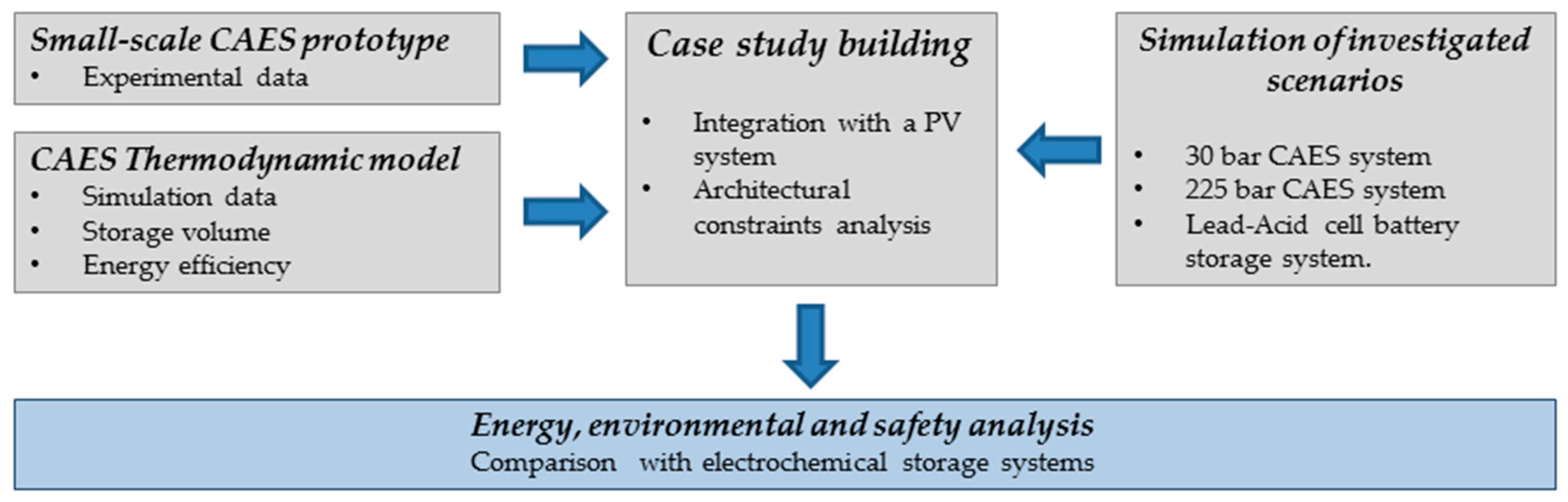
The performance of a CAES (compressed air energy storage) system coupled to a PV plant is studied as a storage system for building applications by the combination of data from the operation of a small-size prototype and the results of the thermodynamic model. The small-size CAES system is composed by a compression section, a high-pressure vessel, and an air expansion section. The air storage section can be constituted by a custom-fitted storage vessel. The small-size prototype was designed, assembled, and installed in the Laboratory of Applied Physics of the Engineering Department of Terni, University of Perugia.
The proposed thermodynamic model is used to investigate and predict the overall electrical efficiency, considering the energy absorbed by the compression section, constituted by the excess power supplied by the PV system, and the energy produced by the expansion section.
Data from the experimental prototype and the thermodynamic model are applied to a case study building. In particular, the performance of the proposed coupled PV–CAES energy storage system has been evaluated on a daily base for an historical building located in Città di Castello (Perugia, Italy). The PV system has been designed, taking into account the architectural constraints of the building. The energy produced by the PV system has been calculated. The PV energy excess has been calculated as the difference between the PV production and the reference daily energy consumption of a single-family dwelling.
Three different storage scenarios have been simulated: one small-size CAES, characterized by a 30 bar-compressor, one small-size CAES, characterized by a 225 bar-compressor, and for the sake of base comparison, a commercial lead–acid cell battery storage system.
A flowchart that depicts the steps of the research is shown in Figure 1.
2.1. Experimental Apparatus
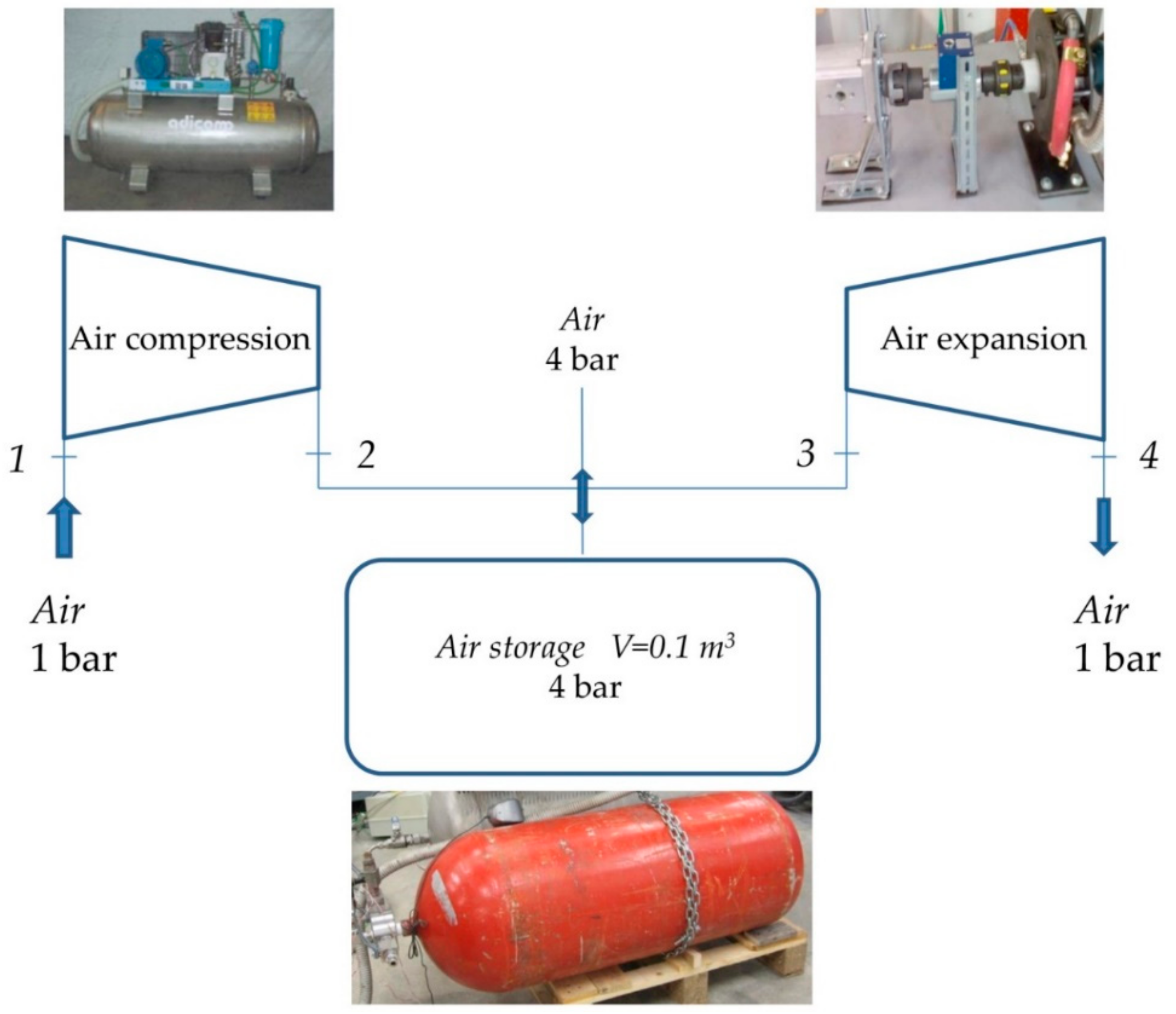
The scheme of the experimental apparatus introduced in the previous section, which is installed at the Laboratory of Applied Physics of the Engineering Department of Terni, is shown in Figure 2.
Air is compressed through an air-cooled two-stage reciprocating compressor supplied by Adicomp Italy. The maximum outlet pressure is 35 bar with a flow rate of 4 Nm3 h−1. The reciprocating compressor is coupled with an electric motor by belts. Compressed air is uploaded in a steel vessel with a total internal volume of 100 L. The air expansion section is constituted by a quasi-turbine, coupled with a mechanical load, supplied by Quasiturbine [40]. The QT is a pistonless machine using a deformable rotor whose blades (sides) are hinged at the vertices. The volume is enclosed between the blades of the rotor and the stator casing. The technical data of the apparatus that is used for the numerical simulation are summarized in Table 1.
2.2. Thermodynamic Model
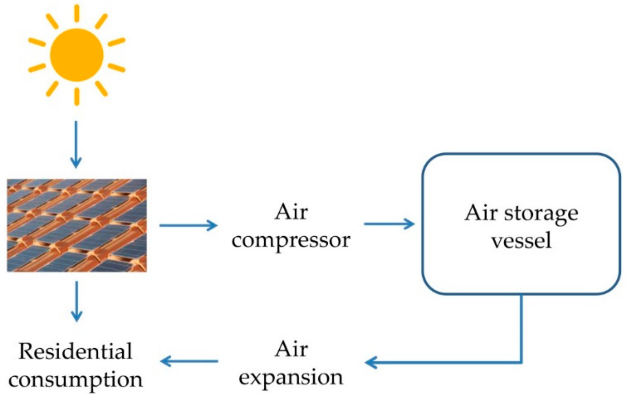
Technical data of the experimental apparatus have been used to carry out an energy analysis, in which the CAES system is associated with a residential PV plant, as shown in Figure 3.
The system is assumed to complete daily cycles, constituted by a compression phase and a production phase. The PV array firstly supplies energy to users. The excess power is used to compress air. The energy absorbed by the compressor is calculated according to Equations (1)–(4).
Equations (1) and (2) are used in an iterative sequence. The convergence value of specific heat and isentropic temperature that are obtained at the end of the air compression phase, respectively Cp1–2s and T2s, is used to calculate the compression enthalpy change (kJ kg−1) in Equation (3) [41]. The isentropic efficiency ηcompr is considered equal to 0.8. Equation (4) gives the compression energy consumption, considering the air mass flowed through the compressor.
Given the air-flow rate elaborated by the compressor, outlet air pressure, and the time in which excess PV power is available, the storage vessel volume can be calculated from the ideal gas equation (Equation (5)).
Referring to the production phase, the expander operates with a fixed pressure of four bars and handles a mass flow rate of 0.024 kg s−1. The energy produced by the quasi-turbine in the expansion phase is calculated with Equations (6)–(9):
Equations (6) and (7) are used in an iterative sequence. The convergence value of specific heat and isentropic temperature obtained at the end of the air expansion phase, respectively Cp3–4s and T4s, is used to calculate the expansion enthalpy change (kJ kg−1) in Equation (8) [41]. The isentropic efficiency ηexp is considered equal to 0.8. Equation (9) gives the expansion energy production, considering the air mass flowed through the quasi-turbine.
The overall electrical efficiency is calculated by Equation (10):
3. Results
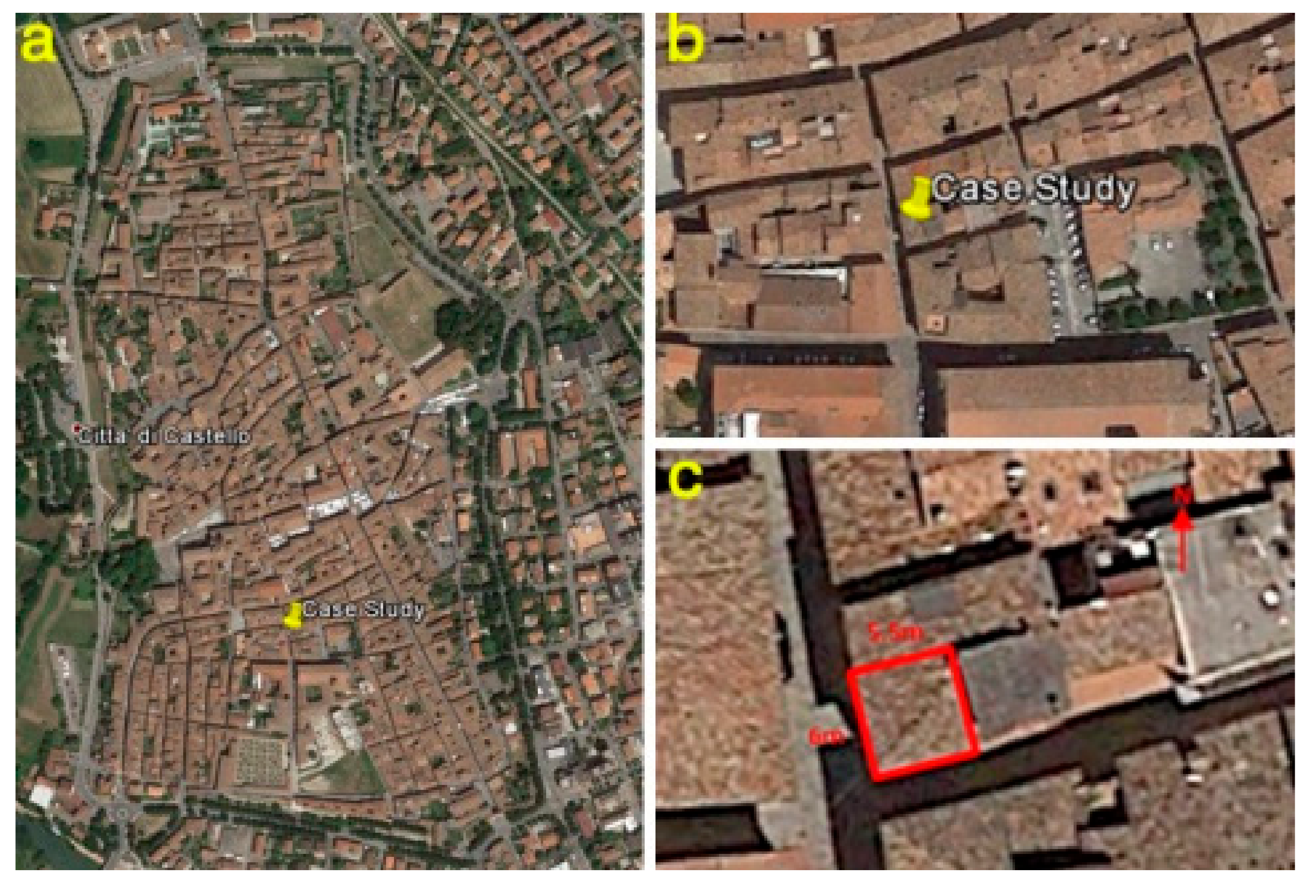
Experimental and simulation data are applied to a case study building, which is a residential building in Città di Castello, a city located in Central Italy (43°28′12″ N 12°13′53″ E) that has a very long history and whose historical centre is delimited by historical walls. The selected residential building is positioned within the historical walls, within the historical center. It is a three-storey building (a ground floor, first floor, second floor, and an attic) with a total area of 280 m2. The aerial view of the historical centre and the case study building is shown in Figure 4. The available roof surface for PV installation is about 33 m2. The sloped roof has an inclination of about 20°.
In order to foresee the installation of a PV system to integrate with the CAES, it is necessary to carry out some considerations. Firstly, the historical center of a city represents a reference point for city life, the place where people meet and that tells the story and the life of those who built it, especially when it is redeveloped and modernized. Thus, the installation of PV systems might lead to a contrast between the past and the future, from traditional historical beauty and technological innovation.
However, there are Italian standards to obey for the installation of PV systems in historical centers: in particular, the installation of PV systems is allowed if no visual impact and a perfect architectural integration are ensured. In light of the above-mentioned rules, to our purposes, the installation of photovoltaic roof tiles (Figure 5) Ma.Xi.Ma by Industrie Cotto Possagno has been selected. The PV-equipped tile is composed of a terracotta tile integrated with a PV module in monocrystalline silicon. It takes a surface of about 10.5 m2 to install a 1-kWp system with 1000 Wm−2 solar insolation [42].
The calculation of the power generated by the selected PV system has been carried out with the help of the PVgis tool [43]. The maximum global clear-sky irradiance in Città di Castello is 938 W·m−2, which is calculated for an average day of July at midday [43].
A 3-kWp crystalline silicon system has been considered. The estimated losses due to the PV dependence on its operating temperature and the degree of insolation have been set to 10.5% (using local ambient temperature). The estimated loss due to angular reflectance effects has been set to 2.8%. The system inclination is 20°. Since the roof of the building is duo-pitched, the system has been orientated as 45° (S-E orientation) and −135° (N-W orientation).
The calculation, carried out by PVgis tool, provides the average monthly electricity production from the system (kWh) as in [43].
Figure 6 shows the total estimated PV energy production, given by the sum of the southeast-oriented PV system and northwest-oriented PV system (Table 2), and the energy consumption was registered in 2016. In particular, building energy consumption has been yearly monitored, and data from domestic meters have been collected.
The small-size CAES system is assumed to operate on a daily basis with the compression phase occurring when there is excess PV energy and the expansion phase occurring to satisfy users’ energy consumption when the PV production is not sufficient. For the simulation, July average daily energy profiles have been used, as shown in Table 3. In fact, July is the month with the highest PV production with a significant energy excess to be stored. During winter, energy production decreases by a factor of four, and the storage system does not store enough energy to be reused to supply the quasi-turbine.
4. Discussion
Excess PV energy for the air compression phase is available in the morning, except for the consumption peak at 8 am, and during the day until 6 pm (Figure 7). During the rest of the day and into the night, solar energy is not produced, and therefore, air expansion should be activated.
The compressor works for 12 h during the day, with a flow rate of 4 Nm3 h−1. According to the thermodynamic model, the compression phase absorbs 8.702 kWh of PV energy excess (32.3%). The compressed air at 30 bars is stored in a vessel with a volume of 1.7 m3. Considering that the minimum pressure inside the vessel is four bars, the quasi-turbine elaborates a flowrate of 0.024 kg s−1 for a maximum period of 38 min. The expansion phase produces 1.008 kWh, which covers 21.9% of the residential energy demand. The electrical efficiency of a daily cycle is equal to 11.6%.
The obtained efficiency is consistent with data in the literature, which referred to the same expansion technology. In Manfrida et al. [44], the same air expander was coupled with a 200-bar two-stage compression section formed by a screw unit and a reciprocating unit. The small-scale CAES system was used to store excess PV energy with efficiency in the range from 11% to 17%.
There are few other experimental tests on the integration of a CAES at a building scale. In Maia et al. [31], a micro-CAES was built adapting an automotive turbocharger to work with a generator, a lubricating system, and an electrical circuit with a 3.5-kW output. The study focuses on the generated energy, but no data are available on the absorbed energy, so that a comparison on the overall efficiency is not possible.
In accordance with Equation (5), the global volume occupied by the CAES system is about 2.5 m3. The small-scale compressed air energy storage system might be positioned in the underground unoccupied areas of the building. Indoor space, which could be addressed to house the CAES system, is a concern especially in historical buildings and requires a site-specific design. A reduction in the occupied volume and an increase in the stored energy is achieved using a more appropriate compression unit characterized by: a flow rate of 4.8 Nm3 h−1, an operating pressure of 225 bar, and an output power of 2.6 kW. In this case, the compressor absorbs 25.849 kWh of PV energy excess (96.0%). The compressed air at 225 bars is stored in a vessel with a volume of 0.25 m3. The expansion phase produces 1.273 kWh, which covers 26.0% of the residential energy demand.
Renewable energy storage in residential buildings is an innovative application for CAES systems, which are historically deployed for large-scale grid management. Residential energy storage is traditionally addressed by batteries. Commercial lead–acid cell batteries (12 V/200 Ah) with an efficiency of 80% can be used to store the energy excess: 28 units in particular are needed to store 26.9 kWh (100% of PV energy excess) for a total occupied volume of 0.85 m3 (single unit size: 0.52 m × 0.24 m × 0.24 m). They are able to cover 100% of the entire energy demand, which is equal to 4.6 kWh.
So, in this scenario, the battery system has the advantage of absorbing and delivering energy more effectively than the small-scale CAES system. The lower efficiency of the CAES system is mainly due to the technology used in the expansion phase. Even though the investigation shows that CAES in buildings, even historical ones with architectural constraints, is technically feasible, it is quite far from parity if compared to electrochemical energy storage in terms of energy efficiency.
On the other hand, some limitations should be considered in the design phase: with a depth of discharge of 50%, the number of charge/discharge cycles are 1200. Since the storage system operates on a daily base, the lifetime is four years, which is not comparable with the CAES lifetime equal to 15–20 years.
Another consideration is connected to the winter operation. Solar PV panels generate far less energy in winter, so the surplus solar electricity may not be generated to fully charge the battery during the winter months. Leaving a battery partially discharged for long periods can further reduce its lifetime. This is particularly the case for lead–acid batteries.
The batteries’ short service life leads to environmental and disposal concerns due to the contained hazardous material. Volume occupancy is another design constraint to be taken into account: a volume of 0.25 m3 is occupied by a 225-bar CAES system, while a volume of 0.85 m3 is occupied by the battery system. In addition, batteries present some safety concerns, which are related to the presence of toxic, corrosive, poisonous, or carcinogenic pollutants and the risk of explosive events. Due to these concerns, batteries are usually installed in dedicated rooms that are physically separated from other areas, with doors and partitions designed to meet the required fire resistance rating. Such aspects become more significant in the case of historical buildings with architectural constraints, in which retrofit actions are often limited. Therefore, the gap identified in the research context, i.e., exploring the CAES system design with experimental data of CAES performance together with a proper comparison with batteries accounting for technology lifespan, is attempted to fill the design and simulation of the proposed system in a constrained environment: the listed building.
Since experimental data at the small scale (e.g., 1–10 kW) are limited, the future research work will be devoted to: (i) obtaining an improvement of the prototype (efficiency, testing of a different expansion technology); and (ii) determining guidelines for site-specific design to give a contribution to future policy implementation.
Once the aforementioned results are obtained, the applicability of the proposed solution might be assessed also as a de facto solution for the listed building retrofit.
5. Conclusions
The paper deals with the integration of renewable energy production and storage in a historical building characterized, for its location, by architectural peculiarities and constraints.
A PV tile system, according to the Italian standards that give rules for the installation of PV in historical centers, has been designed in order to ensure the production of 3 kWp.
The integration of the PV system with the CAES system has been optimized with the aim of exploiting the surplus energy produced by the PV system that is not consumed by the users and the appliances of the buildings to compress the air in order to expand it in the quasi-turbine and produce energy when the PV production is not enough.
For an average summer day, according to the typical daily energy consumption of a residential building, the available energy from PV production that can be used for air compression amounts to 26.9 kWh day−1. Considering a compressor with a flow rate of 4 Nm3 h−1, the compression phase absorbs 8.702 kWh of PV energy excess to store the compressed air at 30 bars in a vessel of 1.7 m3. The quasi-turbine expands for a maximum period of 38 min and produces 1.008 kWh, which covers 21.9% of the residential energy demand. Thus, since the electrical efficiency of a daily cycle is equal to 11.6%, its consistency with other data in the literature makes the integration viable for building application.
The small-size 30 bar-compressor CAES system is compared to a small-size CAES characterized by a 225 bar-compressor and a commercial lead–acid cell battery storage system. With a 225-bar compression section, 96.0% of PV energy excess is stored in a volume of 0.25 m3. The expansion phase produces 1.273 kWh, which covers 26.0% of the residential energy demand. A lead–acid cell battery storage system with 80% charge efficiency is able to cover 100% of the entire energy demand, which equal to 4.6 kWh. The overall efficiency of the CAES system is lower than an electrochemical storage system with battery. So, even though there is no parity in terms of energy efficiency between CAES and batteries, the design of retrofit actions in historical buildings is site-specific and involves service life, safety concerns, and volume occupancy. It can be concluded that the novelty of this study is to introduce experimental data of a CAES prototype that is suitable for dwelling applications as well as its integration accounting for architectural constraints in order to show the viability of this energy solution, even in a constrained environment. Moreover, the need for considering all of the aspects of such a design is crucial to take the correct decision. This is demonstrated by the issue of technology lifespan. The battery performs better than CAES in a single cycle but in a techno-economic analysis both from a user and an energy service company perspective, batteries must be substituted four times in 20 years, while the same CAES can be used. This implies changes in the assessment of the investment costs as well in the environmental impact of the generated waste and their treatment.
Author Contributions
Conceptualization, B.C. and E.M.; Methodology, B.C. and B.N.; Software, B.C.; Formal Analysis, E.M.; Investigation, A.N.; Resources, F.R.; Data Curation, E.M. and A.N.; Writing-Original Draft Preparation, B.C., E.M. and B.N.; Writing-Review & Editing, A.N. and F.R.; Supervision, F.R.; Project Administration, B.C. and A.N.; Funding Acquisition, F.R.
Funding
This research received no external funding.
Acknowledgments
The authors thank the reviewers for the valuable suggestions.
Conflicts of Interest
The authors declare no conflict of interest.
Nomenclature
| Symbol | Unit | Description |
| a | kJ kg−1 K−1 | Langen coefficient |
| b | kJ kg−1 K−2 | Langen coefficient |
| cP | kJ kg−1 K−1 | Specific heat at costant pressure |
| k | - | Heat capacity ratio |
| m | kg | Air mass |
| P | bar | Pressure |
| T | K | Temperature |
| V | m3 | Volume |
| W | kJ | Energy |
| β | - | Compression ratio |
| γ | - | Expansion ratio |
| Δh | kJ kg−1 | Isentropic enthalpy |
| η | - | Isentropic efficiency |
References
- International Electrotechnical Commission. Electrical Energy Storage: White Paper; International Electrotechnical Commission: Geneva, Switzerland, 2011. [Google Scholar]
- Noussan, M.; Jarre, M.; Roberto, R.; Russolillo, D. Combined vs separate heat and power production–primary energy comparison in high renewable share contexts. Appl. Energy 2018, 213, 1–10. [Google Scholar] [CrossRef]
- Beaudin, M.; Zareipour, H.; Schellenberglabe, A.; Rosehart, W. Energy storage for mitigating the variability of renewable electricity sources: An updated review. Energy Sustain. Dev. 2010, 14, 302–314. [Google Scholar] [CrossRef]
- Rossi, F.; Castellani, B.; Nicolini, A. Benefits and challenges of mechanical spring systems for energy storage applications. Energy Procedia 2015, 82, 805–810. [Google Scholar] [CrossRef]
- Nair, N.C.; Garimella, N. Battery energy storage systems: Assessment for small-scale renewable energy integration. Energy Build. 2010, 42, 2124–2130. [Google Scholar] [CrossRef]
- Wang, J.; Lu, K.; Ma, L.; Wang, J.; Dooner, M.; Miao, S.; Li, J.; Wang, D. Overview of Compressed Air Energy Storage and Technology Development. Energies 2017, 10, 991. [Google Scholar] [CrossRef]
- Droege, P. Urban Energy Transition: from Fossil Fuel to Renewable Power; Elsevier: Amsterdam, The Netherlands, 2008. [Google Scholar]
- Jannelli, E.; Minutillo, M.; Lubrano Lavadera, A.; Falcucci, G. A small-scale CAES (compressed air energy storage) system for stand-alone renewable energy power plant for a radio base station: A sizing-design methodology. Energy 2014, 78, 313–322. [Google Scholar] [CrossRef]
- Kim, Y.-M.; Lee, J.-H.; Kim, S.-J.; Favrat, D. Potential and Evolution of Compressed Air Energy Storage: Energy and Exergy Analyses. Entropy 2012, 14, 1501–1521. [Google Scholar] [CrossRef] [Green Version]
- Lund, H.; Østergaard, P.A.; Connolly, D.; Ridjan, I.; Mathiesen, B.V.; Hvelplund, F.; Thellufsen, J.Z.; Sorknæs, P. Energy storage and smart energy systems. Int. J. Sustain. Energy Plan. Manag. 2016, 11, 3–14. [Google Scholar]
- Amelio, M.; Barbarelli, S.; Rovense, F.; Scornaienchi, N.M. Possibility of employing a small power tangential flow turbine prototype in a micro solar concentration plant. Int. J. Heat Technol. 2017, 35, 785–792. [Google Scholar] [CrossRef]
- Yu, Y.; Chen, H.; Chen, L. Comparative Study of Electric Energy Storages and Thermal Energy Auxiliaries for Improving Wind Power Integration in the Cogeneration System. Energies 2018, 11, 263. [Google Scholar] [CrossRef]
- Arigliano, A.; Caricato, P.; Grieco, A.; Guerriero, E. Producing, storing, using and selling renewable energy: The best mix for the small medium industry. Comput. Ind. 2014, 65, 408–418. [Google Scholar] [CrossRef]
- Cerino Abdin, G.; Noussan, M. Electricity storage compared to net metering in residential PV applications. J. Clean. Prod. 2018, 176, 175–186. [Google Scholar] [CrossRef]
- Lund, H.; Salgi, G.; Elmegaard, B.; Andersen, A.N. Optimal operation strategies of compressed air energy storage (CAES) on electricity spot markets with fluctuating prices. Appl. Therm. Eng. 2009, 29, 799–806. [Google Scholar] [CrossRef] [Green Version]
- Luo, X.; Wang, J.; Dooner, M.; Clarke, J.; Krupke, C. Overview of Current Development in Compressed Air Energy Storage Technology. Energy Procedia 2014, 62, 603–611. [Google Scholar] [CrossRef]
- Gu, Y.; McCalley, J.; Ni, M.; Bo, R. Economic Modeling of Compressed Air Energy Storage. Energies 2013, 6, 2221–2241. [Google Scholar] [CrossRef] [Green Version]
- Castellani, B.; Presciutti, A.; Filipponi, M.; Nicolini, A.; Rossi, F. Experimental investigation on the effect of phase change materials on compressed air expansion in CAES plants. Sustainability 2015, 7, 9773–9786. [Google Scholar] [CrossRef]
- De Santoli, L.; Mancini, F.; Nastasi, B.; Ridolfi, S. Energy retrofitting of dwellings from the 40’s in borgata trullo–Rome. Energy Procedia 2017, 133, 281–289. [Google Scholar] [CrossRef]
- Vialetto, G.; Noro, M.; Rokni, M. Innovative household systems based on solid oxide fuel cells for the Mediterranean climate. Int. J. Hydrog. Energy 2015, 40, 14378–14391. [Google Scholar] [CrossRef]
- Lo Basso, G.; Rosa, F.; Astiaso, D.G.; Cumo, F. Hybrid systems adoption for lowering historic buildings PFEC (primary fossil energy consumption)—A comparative energy analysis. Renew. Energy 2018, 117, 414–433. [Google Scholar] [CrossRef]
- Garcia, D.A.; Di Matteo, U.; Cumo, F. Selecting eco-friendly thermal systems for the "vittoriale degli italiani" historic museum building. Sustainability 2015, 7, 12615–12633. [Google Scholar] [CrossRef]
- Astiaso Garcia, D. Green areas management and bioengineering techniques for improving urban ecological sustainability. Sustain. Cities Soc. 2017, 30, 108–117. [Google Scholar] [CrossRef]
- Pennacchia, E.; Tiberi, M.; Carbonara, E.; Garcia, D.A.; Cumo, F. Reuse and upcycling of municipalwaste for zeb envelope design in european urban areas. Sustainability 2016, 8, 610. [Google Scholar] [CrossRef]
- De Santoli, L.; Lo Basso, G.; Nastasi, B. Innovative Hybrid CHP systems for high temperature heating plant in existing buildings. Energy Procedia 2017, 133, 207–218. [Google Scholar] [CrossRef]
- Tronchin, L.; Manfren, M.; Tagliabue, L.C. Optimization of building energy performance by means of multi-scale analysis – Lessons learned from case studies. Sustain. Cities Soc. 2016, 27, 296–306. [Google Scholar] [CrossRef]
- Zafirakis, D.; Kavadias, K.; Kondili, E.M.; Kaldellis, J.K. Optimum Sizing of PV-CAES Configurations for the Electrification of Remote Consumers. In Computer Aided Chemical Engineering; Klemeš, J.J., Varbanov, P.S., Liew, P.Y., Eds.; Elsevier: Amsterdam, The Netherlands, 2014; Volume 33, pp. 1135–1140. [Google Scholar]
- Noussan, M.; Nastasi, B. Data Analysis of Heating Systems for Buildings—A Tool for Energy Planning, Policies and Systems Simulation. Energies 2018, 11, 233. [Google Scholar] [CrossRef]
- Ibrahim, H.; Younès, R.; Basbous, T.; Ilinca, A.; Dimitrova, M. Optimization of diesel engine performances for a hybrid wind–diesel system with compressed air energy storage. Energy 2011, 36, 3079–3091. [Google Scholar] [CrossRef]
- Yang, C.; Wang, X.; Huang, M.; Ding, S.; Ma, X. Design and simulation of gas turbine-based CCHP combined with solar and compressed air energy storage in a hotel building. Energy Build. 2017, 153, 412–420. [Google Scholar] [CrossRef]
- Maia, T.A.C.; Barros, J.E.M.; Filho, B.J.C.; Porto, M.P. Experimental performance of a low cost micro-CAES generation system. Appl. Energy 2016, 182, 358–364. [Google Scholar] [CrossRef]
- Minutillo, M.; Lubrano, L.A.; Jannelli, E. Assessment of design and operating parameters for a small compressed air energy storage system integrated with a stand-alone renewable power plant. J. Energy Storage 2015, 4, 135–144. [Google Scholar] [CrossRef]
- Cazzaniga, R.; Cicu, M.; Rosa-Clot, M.; Rosa-Clot, P.; Tina, G.M.; Ventura, C. Compressed air energy storage integrated with floating photovoltaic plant. J. Energy Storage 2017, 13, 48–57. [Google Scholar] [CrossRef]
- Sciacovelli, A.; Li, Y.; Chen, H.; Wu, Y.; Wang, J.; Garvey, S.; Ding, Y. Dynamic simulation of Adiabatic Compressed Air Energy Storage (A-CAES) plant with integrated thermal storage–Link between components performance and plant performance. Appl. Energy 2017, 185, 16–28. [Google Scholar] [CrossRef]
- Mazloum, Y.; Sayah, H.; Nemer, M. Dynamic modeling and simulation of an Isobaric Adiabatic Compressed Air Energy Storage (IA-CAES) system. J. Energy Storage 2017, 11, 178–190. [Google Scholar] [CrossRef]
- Geissbühler, L.; Becattini, V.; Zanganeh, G.; Zavattoni, S.; Barbato, M.; Haselbacher, A.; Steinfeld, A. Pilot-scale demonstration of advanced adiabatic compressed air energy storage, Part 1: Plant description and tests with sensible thermal-energy storage. J. Energy Storage 2018, 17, 129–139. [Google Scholar] [CrossRef]
- Houssainy, S.; Janbozorgi, M.; Kavehpour, P. Thermodynamic performance and cost optimization of a novel hybrid thermal-compressed air energy storage system design. J. Energy Storage 2018, 18, 206–217. [Google Scholar] [CrossRef]
- Ferretto, F.; Stoppato, A.; Destro, N.; Benato, A. Modelling of the annual performance of a CAES plant and relative economic analysis. In Proceedings of the International Conference on Efficiency, Costs, Optimization, Simulation and Environmental Impact of Energy Systems ECOS 2015, Pau, France, 30 June–3 July 2015. [Google Scholar]
- Ciulla, G.; Galatioto, A.; Ricciu, R. Energy and economic analysis and feasibility of retrofit actions in Italian residential historical buildings. Energy Build. 2016, 128, 649–659. [Google Scholar] [CrossRef]
- Quasiturbine. Available online: http://quasiturbine.promci.qc.ca/ (accessed on 13 June 2018).
- Eastop, T.D.; Mcconkey, A. Applied Thermodynamics for Engineering Technologists; Longman Scientific & Technical and John Wiley & Sons Inc.: New York, NY, USA, 1993. [Google Scholar]
- Industrie Cotto Possagno S.p.A. Via Molinetto. 80-31054 Possagno (TV)[email protected]. Ma.Xi.Ma. Available online: http://www.cottopossagno.com/download/Maxima%20FV%20rossa%20esploso%20scheda.pdf (accessed on 1 June 2018).
- Photovoltaic Geographical Information System (PVGIS). Available online: http://re.jrc.ec.europa.eu/pvgis/apps4/pvest.php# (accessed on 10 June 2018).
- Manfrida, G.; Secchi, R. Performance prediction of a small size adiabatic compressed air energy storage system. In Proceedings of the International Conference on Efficiency, Costs, Optimization, Simulation and Environmental Impact of Energy Systems ECOS 2014, Turku, Finland, 15–19 June 2014. [Google Scholar]
Figure 1.
Flowchart with the steps of the research.

Figure 2.
Experimental apparatus.

Figure 3.
Compressed air energy storage (CAES) system associated with a residential photovoltaic (PV) plant.
Figure 3.
Compressed air energy storage (CAES) system associated with a residential photovoltaic (PV) plant.

Figure 4.
Aerial view of the historical centre and the case study building: (a) historical centre and case study; (b) case study area; (c) case study building.
Figure 4.
Aerial view of the historical centre and the case study building: (a) historical centre and case study; (b) case study area; (c) case study building.

Figure 5.
(a) Selected PV tile; (b) installation example.

Figure 6.
Monthly building electricity consumption in 2016 and estimated PV energy production.

Figure 7.
Daily profile: energy consumption; energy produced by PV; energy available for air compression.
Figure 7.
Daily profile: energy consumption; energy produced by PV; energy available for air compression.


Table 1.
Technical data of the experimental apparatus.
| Compressor | ||
|---|---|---|
| Gas to be compressed | air | |
| Aspiration pressure | mbar(g) | 20–30 |
| Outlet pressure | bar(g) | 25–30 |
| Maximum outlet pressure | bar(g) | 35 |
| Effective flow | Nm3 h−1 | 4.0 |
| Output power shaft | kW | 2.1 |
| Electric motor nominal power | kW | 2.2 |
| Efficiency | % | 83.3 |
| Dimensions | ||
| Length | mm | 1050 |
| Width | mm | 500 |
| Height | mm | 900 |
| Expansor | ||
| Gas to be compressed | air | |
| Intake pressure | bar(g) | 4 |
| Effective flow | N h−1 | 65 |
| Output power shaft | kW | 1.5 |
| Maximum torque | Nm | 30 |
| Efficiency | % | 84 |
| Dimensions | ||
| Diameter | mm | 203 |
| Thickness | mm | 64 |
| Weight | kg | 9 |
Table 2.
Average monthly electricity production from the system.
| Month | 1.5 kWp PV Southeast Orientation [kWh] | 1.5 kWp PV Northwest Orientation [kWh] |
|---|---|---|
| Jan. | 66.7 | 30.8 |
| Feb. | 97.7 | 53 |
| Mar. | 151 | 106 |
| Apr. | 176 | 145 |
| May | 212 | 192 |
| Jun. | 224 | 210 |
| Jul. | 243 | 222 |
| Aug. | 216 | 181 |
| Sep. | 166 | 122 |
| Oct. | 122 | 75.3 |
| Nov. | 72.7 | 36.1 |
| Dec. | 61 | 25.3 |
Table 3.
Daily energy calculations.
| Day Hour | Energy Consumption Eusers (kWh) | Energy Produced by PV EPV (kWh) | Energy for Air Compression ECAEScompr (kWh) | Energy to Be Supplied by Air Expansion ECAESexp (kWh) |
|---|---|---|---|---|
| 1 | 0.108 | 0 | 0 | 0.108 |
| 2 | 0.108 | 0 | 0 | 0.108 |
| 3 | 0.108 | 0 | 0 | 0.108 |
| 4 | 0.108 | 0 | 0 | 0.108 |
| 5 | 0.108 | 0 | 0 | 0.108 |
| 6 | 0.108 | 0.348 | 0.240 | 0 |
| 7 | 0.288 | 0.954 | 0.666 | 0 |
| 8 | 2.224 | 1.665 | 0 | 0.558 |
| 9 | 0.42 | 2.342 | 1.922 | 0 |
| 10 | 0.108 | 2.912 | 2.804 | 0 |
| 11 | 0.108 | 3.330 | 3.222 | 0 |
| 12 | 0.108 | 3.567 | 3.459 | 0 |
| 13 | 0.422 | 3.616 | 3.194 | 0 |
| 14 | 0.422 | 3.473 | 3.051 | 0 |
| 15 | 0.256 | 3.142 | 2.886 | 0 |
| 16 | 0.126 | 2.644 | 2.518 | 0 |
| 17 | 0.126 | 2.013 | 1.887 | 0 |
| 18 | 0.263 | 1.308 | 1.045 | 0 |
| 19 | 0.739 | 0.579 | 0 | 0.159 |
| 20 | 1.218 | 0 | 0 | 1.218 |
| 21 | 1.077 | 0 | 0 | 1.077 |
| 22 | 0.785 | 0 | 0 | 0.785 |
| 23 | 0.24 | 0 | 0 | 0.24 |
| 24 | 0.108 | 0 | 0 | 0.108 |
| Total | 26.9 | 4.6 |
© 2018 by the authors. Licensee MDPI, Basel, Switzerland. This article is an open access article distributed under the terms and conditions of the Creative Commons Attribution (CC BY) license (http://creativecommons.org/licenses/by/4.0/).
Share and Cite
MDPI and ACS Style
Castellani, B.; Morini, E.; Nastasi, B.; Nicolini, A.; Rossi, F. Small-Scale Compressed Air Energy Storage Application for Renewable Energy Integration in a Listed Building. Energies 2018, 11, 1921. https://doi.org/10.3390/en11071921
AMA Style
Castellani B, Morini E, Nastasi B, Nicolini A, Rossi F. Small-Scale Compressed Air Energy Storage Application for Renewable Energy Integration in a Listed Building. Energies. 2018; 11(7):1921. https://doi.org/10.3390/en11071921
Chicago/Turabian StyleCastellani, Beatrice, Elena Morini, Benedetto Nastasi, Andrea Nicolini, and Federico Rossi. 2018. "Small-Scale Compressed Air Energy Storage Application for Renewable Energy Integration in a Listed Building" Energies 11, no. 7: 1921. https://doi.org/10.3390/en11071921
Note that from the first issue of 2016, this journal uses article numbers instead of page numbers. See further details here.