Control Strategies in Multi-Zone Air Conditioning Systems


1
Department of Infrastructure Engineering, The University of Melbourne, Melbourne 3010, Australia
2
OAIRO Alliance Ltd, Unit M, Bourne End Business Park, Bucks SL66TG, UK
*
Author to whom correspondence should be addressed.
Energies 2019, 12(3), 347; https://doi.org/10.3390/en12030347
Submission received: 11 December 2018
/
Revised: 16 January 2019
/
Accepted: 18 January 2019
/
Published: 23 January 2019
(This article belongs to the Special Issue Refrigeration, Air Conditioning and Heat Pumps: Energy and Environmental Issues)
Abstract
:In a commercial building, a significant amount of energy is used by the ventilation systems to condition the air for the indoor environments to satisfy the required quantity (temperature and humidity) and quality (amount of fresh air). For many years, Variable Air Volume (VAV) systems have been considered as the most efficient solutions by balancing the airflow volume based on the demand making them energy efficient when compared with the traditional Constant Air Volume (CAV) systems. However, the setpoints in VAV systems are often misread by the sensors due to stratification and formation of pollutant pockets and responding to design levels that overestimate the real-time demand conditions, which result in waste of energy, thermal discomfort and unhealthy air. In general, VAV devices are expensive, complicated and prone to failures and they are used only in medium and large projects. More recently, new technologies have evolved to solve this issue. In one of the new solutions, VAV motors terminals are replaced with flaps which are simpler and less expensive thus, they can be implemented in a wider range of projects. In systems, balancing and supplying the optimal airflow to reduce the energy consumption while delivering ideal thermal and Indoor Air Quality (IAQ) levels are the main challenges. In this paper, a comparison of the recent technologies with traditional VAV systems is presented to be used as a guild line for researchers and designers in the field of Heating Ventilation Air Conditioning (HVAC).
1. Introduction
Climate change, air pollution and global warming are the critical concerns that need immediate action. Even though mitigation measures have been implemented around the world, significant efforts are still required to limit the rise in the global temperature to the 2 °C as stated in the Paris Agreement [1,2,3]. Building sector accounts for approximately 40% of the total world final energy consumption and around one-third of the greenhouse emissions, therefore, it plays an important role to reduce the impact on the environment [4,5,6].
In buildings, the major portion of energy is consumed by the mechanical services, heating and air conditioning systems, with the share of around 50–82% [7,8]. Consequently, during the last decade researchers have focused on the optimisation and development of strategies to improve the efficiency of such systems [9,10]. However, reducing the amount of energy consumed by the air conditioning systems, must not compromise the indoor air quality (IAQ) and thermal comfort [9]. Because as it has been shown, IAQ has a direct impact not only on people’s health and wellbeing but also on their productivity [11] as they spend approximately 90% of their time within indoor environments [12,13].
Typically, ventilation in buildings is provided using heating, ventilation and air conditioning systems (HVAC) that condition air by utilizing either indoor conditioning units that recycle indoor air or centralised air handling units (AHU) that may utilize either indoor or outdoor air and then supply the conditioned air into each zone. Since multiple zones could have different requirements due to differences in the number of occupants, equipment, devices and activities, the ventilation in different terminals may be unevenly distributed producing discomfort. Also, energy could be wasted in over ventilated spaces due to poor equipment control, variability, supply and exhaust fans typically work on an equal basis and work more than required [14].
To address these challenges and reduce the energy consumption by the ventilation system, it is identified that the air distribution system is the critical parameter. Reducing the volume of airflow required by the system, while achieving the appropriate levels of IAQ, will have a significant impact on the overall performance of the HVAC systems [15]. Equally important, if the ventilation system is using less air flow—so that conditioning less air—equipment such as the chiller, cooling towers, pumps and other mechanical services will have a lower load with less energy demand.
Early HVAC systems were based on constant air volume (CAV) controls that condition the spaces by heating/cooling the constant airflow depending on the requirement thus they can only control the temperature of a specific area. Consequently, CAV systems cannot satisfy the temperature requirements in every zone. The variable air volume system (VAV) was later introduced as a novel solution to control the air flow rate in responding to dynamic loads in each zone [16]. In the terminals of the system, VAV boxes measure and control the volume air flow by opening or closing dampers to deliver the required amount of air. Then, the change in the pressure drop in the air ducts, generated by the dampers (30%–100%), triggers a signal to the supply air fan to increase or decrease the air flow [10]. However, despite that the VAV systems are efficient, their performance highly depends on their control strategy [17].
The VAV systems have been implemented since the end of the World War II and became highly popular in the 70’s. Since then, various improvements in the control, measurement techniques and sensors have been developed [18]. More recently different studies have been looking for simpler, more efficient and less expensive solutions to deliver the minimum amount of airflow while endeavouring to provide an ideal IAQ [15]. By using motor flaps—instead of VAV boxes—the air flow could be regulated. However, determining the current airflow becomes a challenge since it cannot be measured directly without significant cost implications. Therefore, the air flow as a direct control parameter must be replaced, for example, by the zone pressure, the static duct pressure, the temperature, CO2 level or a combination of them.
Until now, no attempt has been made to compare the new control strategies for minimising the air flow in multi-zone air conditioning systems. This paper mainly focusses on the investigation and comparison of these control strategies, their control objectives and their control parameters. The main goal is to identify the energy saving potential of each alternative and their impact on the indoor environment. Consequently, the structure of the paper is as follows: Section 2 describes in more detail the problem and the motivation of this paper. Section 3 focused on developments related to VAV systems and their control strategies; Section 4 discussed and compared the modern control strategies to assess their impact on the thermal comfort, IAQ and energy consumption.
2. Background
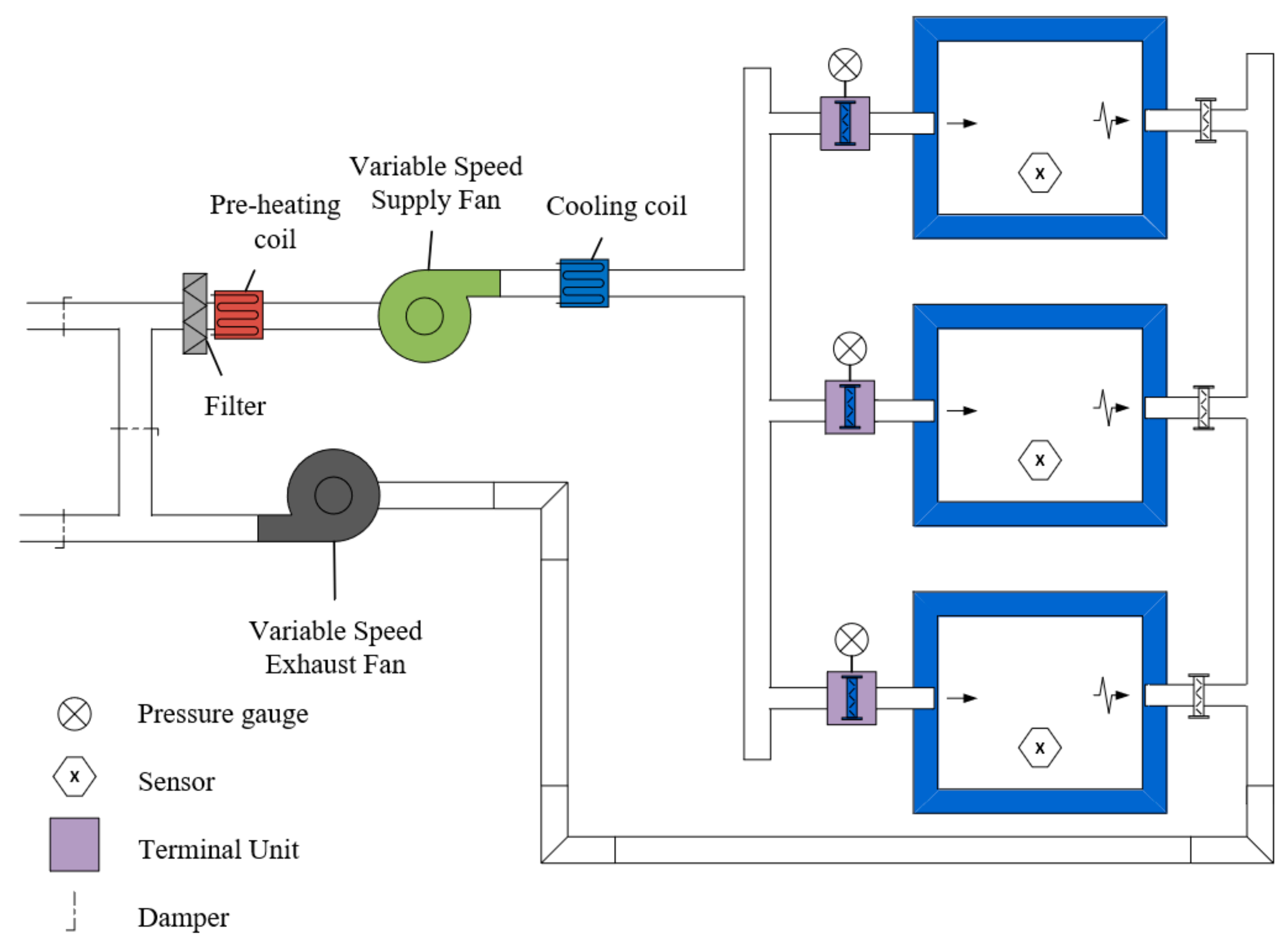
The focus of this literature survey is on modern control strategies that relay on enhancing the balance of airflow within multiple zones to improve the energy consumption of the HVAC system. Furthermore, it focuses on the assessment of each control strategy looking at their impact on the thermal comfort as well as IAQ. Figure 1 shows a schematic diagram of a typical VAV system. In general, these systems have a central 1–3 speed AHU that delivers primary air at a defined temperature to terminal boxes in each zone. The terminal boxes or VAV boxes have a primary-air damper controlled automatically. This damper regulates the volume of primary air delivered to the box according to the demand. Since each box regulates the air flow independently, the total volume supplied by the AHU varies according to the demand of all the boxes. Thus, the variable airflow is achieved by controlling the speed of the supply air fan [19].
Regarding the energy consumption of the ventilation system, between all the components, the supply and exhaust fans are responsible for 50% and 33%, respectively [21] hence, conservation measures should be focused in these devices. In addition, it can be demonstrated that the air volume flow has quadratic and cubic relations with the pressure and the power consumption correspondingly. This means that a reduction of the air volume flow by 10% will result in power consumption savings of 27%. In detail, it is critical to reduce the overall air volume flow required by the VAV system to meet the comfort levels as well as avoiding peak periods of high air volume demand followed by low air volume flow demand periods [15].
In conventional systems, VAV boxes play a major role in both energy consumption and thermal comfort as they control the overall airflow required (but struggle with and are restricted to a 30% minimum supply to avoid airdrop) by the system as well as the airflow delivered to each zone. They have multiple components such as a controller, temperature sensor, actuator, damper, reheating coil and air flow sensor [22], VAV boxes are complex devices with embedded electronics which are expensive and prone to failures [15,19]. Hence, they are only applicable to large or medium construction projects [7].
Even though VAV systems are efficient solutions, it is still difficult to minimise the air volume set point. The simplest control solution is to set a constant air flow or a constant static pressure in the air ducts—usually during commissioning—for one specific occupancy scheme. The VAV terminals adjust the damper to deliver the required amount of air in each zone. Then, the supply fan adjusts the air flow to maintain the setpoint. However, often the set points are higher than required because they are not adjustable to the real demand, causing discomfort and waste of energy. As a consequence, many researchers have been focusing their efforts in developing complex control strategies such as Static Pressure Reset (SPR) [18,23], CO2 reset [7,24,25], time average controls [26], fault adaptive controls [19], etc. These strategies are based on empirical, physics-based, data-driven or grey box approaches which are complex and sometimes difficult to implement in existing systems. Additionally, novel strategies are exploring a physical phenomenon known as diffuse ventilation to improve the environmental indoor climate and, at the same time, reduce the energy consumption.
Furthermore, with the aim of reducing complexity, extending the usage of VAV systems to small and medium projects, reducing the costs and ensuring a more efficient usage of the energy as well as a proper IAQ and thermal comfort, different studies have focused in the development or adaptation of control strategies to use motor flaps instead of VAV boxes [15,27]. The primary challenge here is how to estimate and control the air flow without measuring it directly—as the VAV boxes attempt to do.
3. Control Strategies in VAV Systems
VAV systems are more efficient than the constant air volume (CAV) systems because they adjust the amount of air supplied in different zones (with different requirements). However, their efficiency highly depends on the control strategy implemented to balance and distribute the airflow in each conditioned space. Early versions of manufacturers’ control strategies require to define the principal air flow supply volume as a design parameter (usually defined during the commissioning stage of the project) without being determined automatically during the operation. Commonly, this parameter is overestimated so that the temperature in the zones that are being conditioned are normally lower than required (causing discomfort) and the fans work more than necessary (causing energy wastage). This category of control strategies are summarised by Pang et al. [17] as follows:
- Occupied zone set-point temperatures and night set back
- VAV box minimum flow (typically 30%)
- Optimum start
- Supply air temperature reset
- Economiser and minimum outdoor air intake
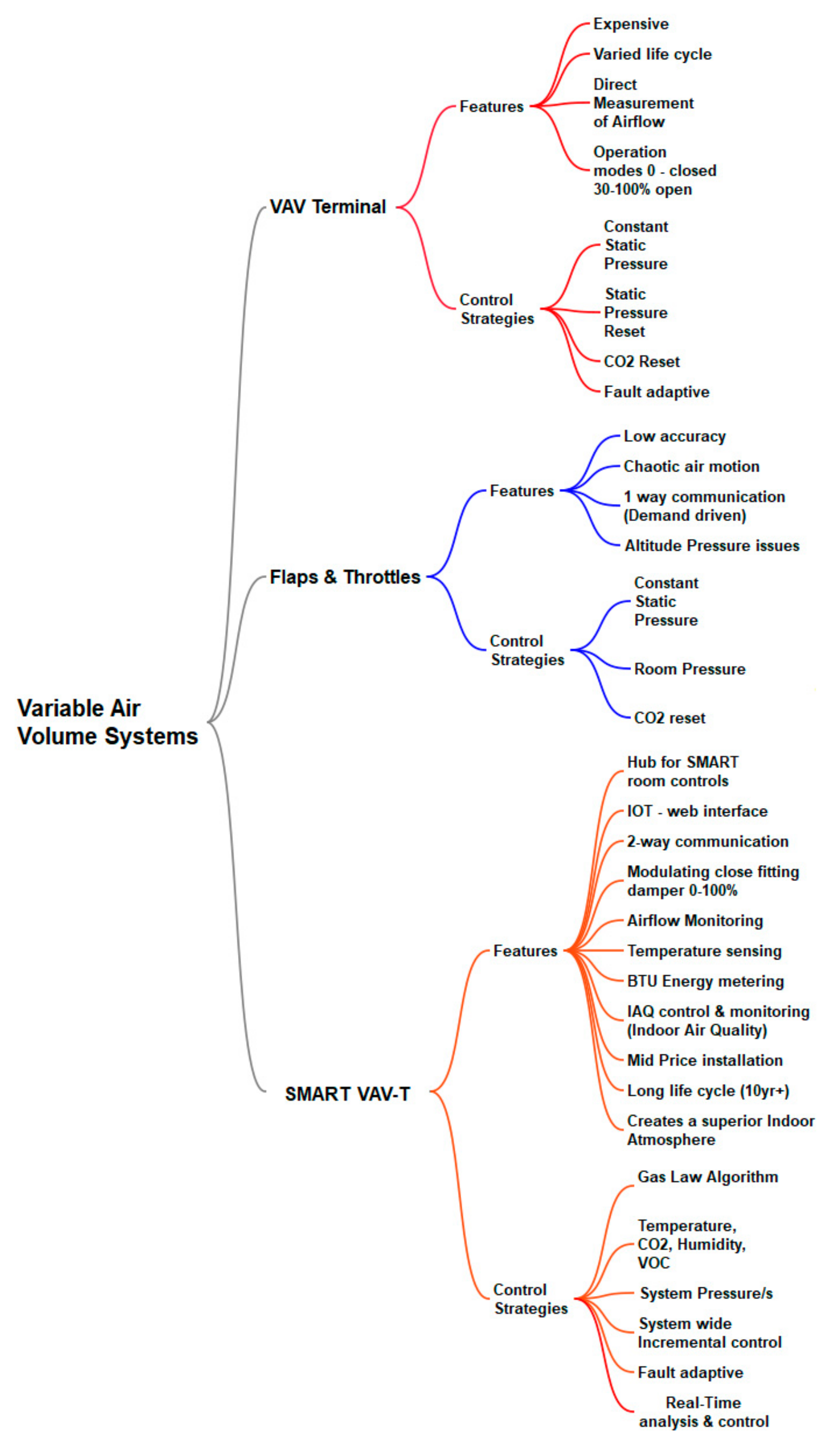
These strategies could be improved since in general they are based on maintaining a constant static pressure (CSP) set-point in the main duct without considering the actual pressure demand. In the following sections different strategies are presented. Figure 2 demonstrate the alternatives and features of different VAV systems.
3.1. Duct Static Pressure-Based Control Strategies
To reduce the supply fan’s energy consumption, different studies have focused on strategies to reset the static pressure setpoint. Early versions of this strategy are based on measuring the airflow rate and mathematical models to determine the static pressure reset setpoint [16,28]. The effectiveness and performance of these solutions are limited by the accuracy of the airflow sensor thus the airflow as a direct feedback parameter is replaced by the position of the VAV boxes damper. This improves the accuracy of the control but increases its complexity as the required mathematical model to describe the relationship between the duct static pressure and the damper position needs to address non-linear and multivariate phenomena with long delay times [29]. For this reason, a solution focused on developing fuzzy control strategies that replace the mathematical models have emerged. The first alternative that is recognised to be more efficient and stable in its category is the Trim and Respond static pressure reset (SPR) control strategy. Koulani et al. [30] studied on its operation and potentials by developing a mathematical model using Simulink and validating it with an experimental setup. This method involves the integration of a building management system (BMS) with the VAV terminals by informing the supply fan with the pressure needed to satisfy the conditions in the most critical zones. Particularly, the Trim & Respond SPR method is based on zone pressure request alarms. In this case, every damper of the VAV system sends an alarm signal when it is open more than 85% and keeps sending the signal until the damper closes to 80%. Additionally, this method resets the pressure set point every 90 sec within a specific pressure range —upper limit is equal to the CSP setpoint and the lower limit is determined according to the pressure demand to guarantee an optimal damper operation. Koulani et al. concluded by simulating the SPR and CSP control strategies and calculating the fan power that the energy consumption is reduced by 14%. However, they did not consider the IAQ parameters in the study.
Zhang et al. [29] developed a strategy where the zone temperature sensor follows its setpoint by adjusting the supply airflow which is controlled by the terminal damper position feedback. Additionally, two sequential controllers are implemented to realize a pressure independent control. The first one uses the temperature of the conditioned space and its setpoint as the inputs to define the supply airflow setpoint. Then, the second one takes the calculated airflow setpoint and the airflow measure to define the position of the damper. This solution ensures a supply airflow to meet the demand according to occupancies’ thermal demand and the indoor load. In particular, this method decreases the terminal damper resistance loss and the system resistance so that a lower static pressure setpoint is achieved as well as better stability.
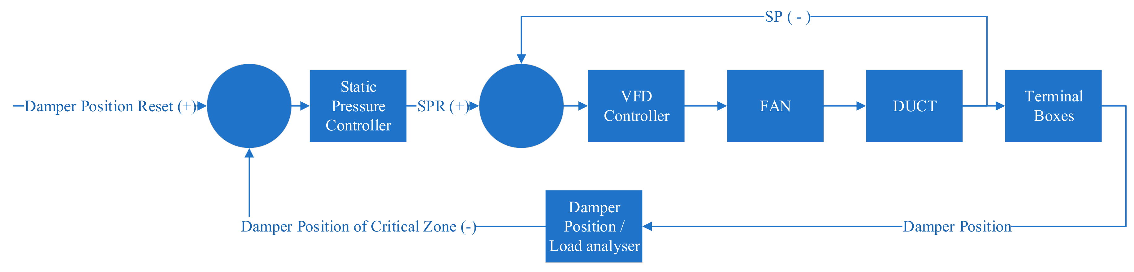
Walaszczyk and Cichón [18] analysed the impact of not only the trim and response strategy but the proportional-integral-derivative (PID) control on the energy consumption of the HVAC system [18]. The last one involves a standard PID control to determine the static pressure set point. Explicitly, as the zone’s demand decreases the zone’s damper begin to close. Then, the duct static pressure setpoint is reduced until the critical zone’s damper is almost open. Walaszczyk and Chichón simulate both strategies and compared them to the CSP method. They found that strategies that reset the duct’s static pressure setpoint have a better performance in terms of energy consumption. Additionally, a small improvement was found using the trim and response alternative over the PID control. Figure 3 illustrates the static pressure reset control strategy based on VAV damper opening.
Later, Rahnama et al. [23] developed a SPR strategy that instead of identifying the critical zone by the position of the dampers (i.e., the airflow rate), it measures the static pressure directly at the terminals. This becomes important as they highlighted that not only the air flow is important, but the dimension and layout of the ducting system are determinant factors. They implemented four conditions to control the system and waiting times between actions to let the system reach balance:
- The air flow at the dampers has not changed and the set point is kept—No action required.
- The total air flow increases but the current pressure setpoint is still enough—No action required
- A wide-open damper triggers a request for air from the beginning. The total flow rate is fixed by increasing the pressure set point until the request is fulfilled.
- A partially open damper turns into a wide-open damper and then send a request for air. The total flow rate is fixed by increasing the pressure set point until the request is fulfilled.
Finally, to evaluate this method, Rahnama et al. developed an experimental mock-up laboratory where the air flow rates were assumed to be known at each terminal damper so that there were no real zone areas and demand-controlled ventilation. They found a considerable reduction of 27%, 36% and 21% in fan power use.
Rahnama et al. [31] have continued their investigation on duct static pressure reset control strategies exploring a solution where the terminal dampers are replaced for decentralised fans. In this case, the main supply fan only compensates the pressure of the zone with the lowest pressure drop (critical zone). The decentralised fans provide the required local pressure to fulfil the demand in the other zones. Two sequential controls regulate the speed of the primary and decentralised fans. The last one can be adapted to respond to zone CO2 levels, occupancy sensors, etc. They implemented this novel solution in an experimental mock-up under different airflow rates. At the end, Rahnama et al. estimated an average reduction of 30% in power use with this new system.
The proliferation of Building Automatization Systems (BMS) made it possible to implement more complex algorithms and exploit a large amount of data that can be recorded. For example, Tukur and Hallinan [32] explored a different approach involving a duct static pressure reset coupled with statistical information. This historical data is used to build a plot to describe the relationship between the system loss coefficient (K) and the weighted mean damper position (D). From the K-D plot, an extensive amount of information to describe the system, can be extracted including: the best damper configurations to deliver a particular condition (quality and quantity of air) and minimise the energy consumption.
More recently, Jing et al. [33] showed that SPR control strategies that use a feedback indicator to reset the static pressure often produce under and over ventilation in different zones. To address this problem, they developed a comprehensive mathematical model to simulate the non-linear phenomena of the ventilation system, this is the relationship between the pressure drop and the airflow at the terminal damper. In addition, they implemented a supervised machine learning algorithm to obtain unknown parameters in the model. Then, they developed a damper position control method to guarantee that the system is well-balanced. Finally, an optimal static-pressure set-point selection method is used to calculate the minimum closed-form static pressure which guarantee the system is energy efficient and delivering the required airflows in each zone. Jing et al validated this strategy and compared it with traditional SPR strategy using an experimental setup. They found energy savings of 21.4% while delivering the desired airflow rates.
3.2. CO2-Based Control Strategies
Until here, the control strategies presented are based on the duct static pressure to balance the air in different zones taking into account the temperature as an input parameter. Indistinct of the method to balance the air flow, CO2 could be used to estimate the strength of occupant-related contaminant sources. For example, Lin and Lau [24] proposed a CO2-based demand control strategy in multi-zone HVAC systems. This is a dynamic reset approach focused on adjusting the outdoor air rate continuously according to the CO2 produced by the occupants and then modulating the dampers to maintain the outdoor air rate at the new set point. Using CO2 or occupancy sensors the system reacts to the variation of occupancy rates in one or more zones as well as to the variation of the system ventilation efficiency. Specifically, the CO2 concentration in each zone, system primary supply and exhaust air, and each zone’s primary airflow volume rate must be measured to implement this approach. Then, the outdoor air rate is determined using ANSI/ASHRAE standards 62.1. The performance of this approach is compared with a single path VAV system by using energy and airflow simulations of a classroom/office building modelled with realistic occupancy schedules. It was found that the average annual system outdoor air rate for the proposed approach was 14.6% less than without a demand-controlled ventilation strategy. Additionally, it was estimated that the monetary saving is between 0.3% and 11%.
The previous alternative focused on the system level—since the minimum airflow rate set-point of a VAV boxes is maintained constant based on the design occupancy of the zone. However, a further saving potential can be exploited at the zone level. For this reason, Liu and Lau [25] developed two additional alternatives to dynamically reset the zone airflow to maintain the system either at a target outdoor airflow rate or at a target system ventilation efficiency. On one side, the first option is called CO2-based DR+ZDR_Vot which has the same previous CO2 dynamic reset for the system outdoor air rate and it adds, at the zone level, a control that resets the airflow minimum set point to decrease the primary outdoor air fraction by increasing the zone airflow rates in the critical zone. On the other hand, the second option is called CO2-based DR+ZDR_Ev which reset the minimum set point of the zone primary airflow to maintain the value of the system efficiency greater or equal to the design value. This can be achieved by modulating the zone airflow rate. Again, the system level strategy is the CO2-based dynamic rest strategy explained previously and the zone level control increases the minimum airflow set-point to decrease the zone outdoor fraction and increase the system ventilation efficiency to a target design efficiency. The same simulations of energy and airflow used in the first part of this study are used to compare and evaluate the performance of these options. The results show that the average annual system outdoor air rates are 44% and 45% less than the values for the VAV system without a demand control strategy. Additionally, the annual monetary savings are between 24% and 46% for the first option and between 26% and 46% for the second option.
Following the CO2 based controls, Kim et al. [22] proposed a VAV terminal unit control method that meets the ventilation requirement to control IAQ by controlling the air flow rate. The idea is to delay the outdoor air inlet time and to reduce the outdoor air flow rate, to control the CO2 concentrations in the conditioned spaces. The following actions are proposed if the requirement of CO2 concentration is not met (less than 1000 ppm):
- Increase the air flow rate of a terminal unit in the critical zone—do not increase the outdoor air flow rate.
- If ventilation CO2 concentration is low, use recirculated air —do not increase the outdoor air flow rate.
- If above actions are not possible, increase the outdoor air flow rate.
At the end, the minimum airflow rate at the terminal is controlled not only by the temperature of the conditioned zones but their CO2 concentration to achieve both thermal comfort and IAQ. Additionally, the proposed solution was compared to a fixed minimum air flow method using TRNSYS 17 by reproducing a case where an AHU is selected to condition eight target spaces. It was found that the target temperature is maintained in both cases, but only with the proposed solution, the IAQ was acceptable. Furthermore, the energy consumption was decreased by 20%.
Previous technologies integrate CO2 based demand controls to guarantee the IAQ together with the thermal comfort and control the air flow using VAV boxes. More recently, different studies are looking for alternatives to the VAV boxes to control the airflow in each zone since they are expensive, complicated, prone to failures and only used in large projects. The challenge of this idea is to find a way to measure and control the air flow without the airflow sensors embedded in the VAV boxes.
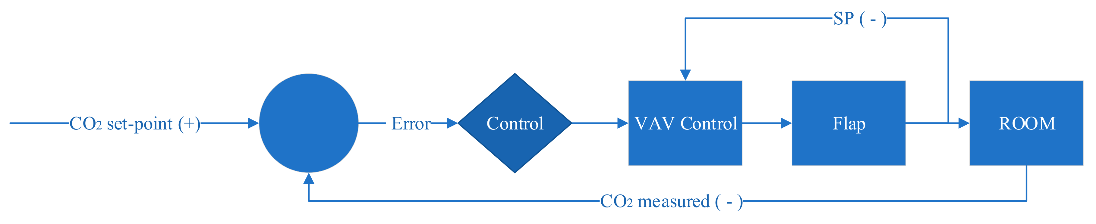
Zucker et al. [15] proposed the implementation of motor flaps instead of the VAV boxes. To replace the flow measurement equipment, they developed a model based on the pressure drop of the air ducts and the CO2 levels to control the flaps positions. In this method, the supply air fan receives a set-point for the differential pressure that needs to be fulfilled, and the flap angle of a motor flap control and the air volume flow that needs to be supplied in each zone. Furthermore, this solution is developed in a way that it can be easily implemented and integrated into building management applications without additional instruments or setups. Thus, the pressure drop within duct segments is not measured directly but calculated with a model based on the system schematics. This implies that the pressure drop model needs to be developed for each duct system and building topology. Figure 4 illustrates the CO2 reset strategy.
Two models work together, the pressure drop model of the system and the CO2 zone model. The first one calculates the current air volume flow into the zone at any moment and adjusts the power of the fan required to fulfil the demand. The second one calculates the CO2 level of the zone depending on the incoming air flow, the number of occupants and the geometry of the zone. In general terms, the supply air fan receives a pressure set-point and update the current pressure to the dynamic model. Afterwards, the motor flaps receive the angle set points. Again, the CO2 level in the zone and the flow volume in each terminal are measured together with the pressure and volume flow at the supply air fan to calculate the new set points.
Zucker et al. validated their approach by comparing their model implemented in MATLAB™ and measuring data collected from a ventilation system in a passive house office building in Vienna, Austria. The estimated investment cost saving of motor flaps compared to VAV controller, is around 55% and the new approach improves the energy efficiency by 5%. However, this approach has a significant modelling effort that does not compensate for the savings thus is not practical for implementation. It was suggested to redefine the modelling strategies by using Building Information Model (BIM) and implementing a grey box modelling to reduce the complexity of the models.
3.3. Fault Tolerant Control Strategies
As it was mentioned earlier, VAV boxes are versatile and flexible devices used to control the airflow and deliver the adequate amount of air in each conditioned space. However, these elements are highly complex, expensive and more importantly prone to failures. These failures need to be identified, isolated and corrected because they have an adverse effect in both, thermal comfort and energy consumption [34]. For this reason, researchers have been focused on the development of fault-adaptive control strategies which consists of two sequential subsystems. The first one provides information about the occurred fault and the second one adapts the control to the faulty operation. As shown by Darure et al. [19], most of the fault-adaptive control strategies are designed to recover the system and the control performance at the cost of higher energy consumption. Instead, they integrate explicitly the energy consumption of the building as an indicator to be minimised under a faulty operation. First, a fault detection and diagnosis module identifies and isolates the damper failure and then, a fault-adaptive control lock-in the issue and makes possible to reduce the energy consumption of the building within desired thermal comfort levels. This solution is tested in a building in the city of Nancy, France.
3.4. Room Pressure-Based Control Strategies
In 2011 a new control strategy for ventilation and conditioning systems was invented by Albert Bauer and patented by Bosch GmbH [27]. It is claimed that this invention allows a cost-efficient and flexible air stream control for improving the comfort and the zone climate. This technology results as an alternative to the volume stream controllers used in conventional systems that, in general, are cost and maintenance intensive and it replaces them by cooperating climate and differential pressure controllers and throttle flaps. It is claimed that, the device controls the inlet and exhaust fans, and the inlet and exhaust throttle flaps in order to maintain the desired levels of zone pressure, room temperature, CO2. These variables become direct control parameters which allow the system to work with the minimum inlet and exhaust fan power so that the energy is used efficiently, while each zone is conditioned independently as desired within a ±2 °C setpoint.
The system is composed of (1) an inlet and exhaust fan in central inlet and exhaust channels; (2) inlet and exhaust throttles in secondary channels that connect each zone with the central channels; (3) climate sensors in each zone to be conditioned (e.g., temperature, humidity and CO2 sensors); (4) pressure sensors in each zone to be conditioned. Additionally, there are different controllers to adjust the throttle openings and the AHU fan power as follows:
- Climate controls:
- ○
- First climate controller: controls each zone’s input throttle flaps opening cross section to ensure the desired zone climate.
- ○
- Second climate controller: adjust the input fan requirements to ensure enough pressure is available to provide the necessary airflow in all zones.
- Pressure controls:
- ○
- First a fine differential pressure sensor (with pressure piping to indoor & outdoor) and controller: controls each zone’s exhaust throttle flaps opening cross section to ensure the desired zone pressure.
- ○
- Second pressure controller: adjust the exhaust fan power required to maintain the desired pressure in all the zones.
- ○
- Third pressure controller: controls each zone’s input throttle flaps opening cross section to ensure the desired zone pressure.
- ○
- Fourth pressure controller: controls the inlet AHU fan power in case that the exhaust fan power is not enough to maintain the zone pressure and climate levels in all the zones.
This controller allows maintaining the duct static pressure at minimum level so that all the zones are supplied with the required amount of fresh air. Additionally, it allows to define and control the pressure within each zone. In this way, it is possible to produce a pressure differential between the zone and the atmosphere. This control system needs constant feedback from number of sensors that are connected via BMS, however, the digital infrastructure of BMS does not allow such heavy load of data transition.
More recently, the advancement in the telecommunication technologies has created the new era of the Internet of Things (IoT). The IoT based sensing technologies have penetrated into the HVAC operation and control systems, creating smart control devices for the ventilation and conditioning the building.
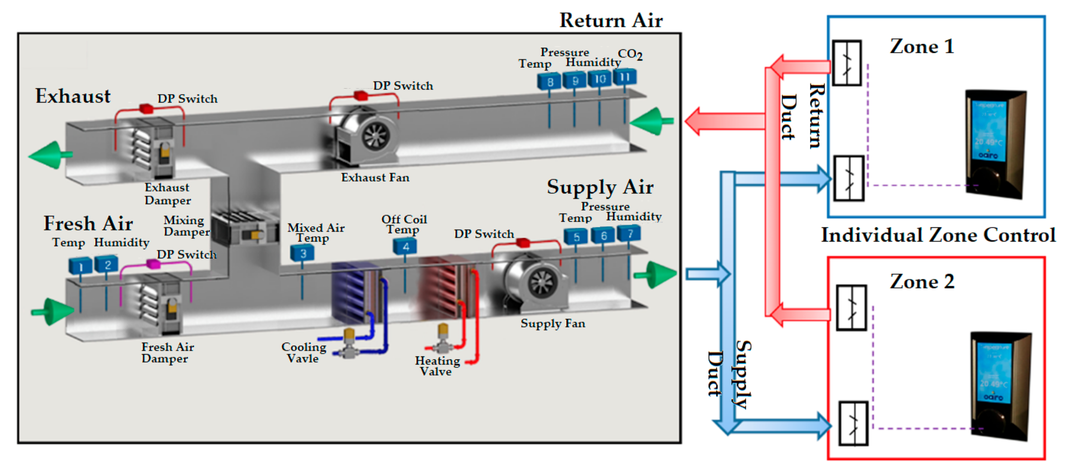
A revolutionary approach called “Atomic Air” was invented by Saxby [35] to create superior indoor atmospheres and is claimed to have mechanical energy savings along with superior IAQ. The system allows a cost-efficient installation for creating superior indoor for each zone [35]. This invention utilises a unique control algorithm based on gas laws while utilizing artificial intelligence to finely tune and control the HVAC plant. The algorithm creates a stochastic molecular motion via high-velocity molecular collisions within the space, this creates a completely diffused atmosphere. The solution controls the energy input (heat/coolth, volume and mass), supply and exhaust fans independently, and the supply and exhaust dampers in order to maintain individual room atmospheres, temperature, CO2 and humidity (Figure 5). These variables become direct control parameters which allow the system to work with the minimum energy input (heat/coolth), supply and exhaust fan power so that the mechanical energy is used efficiently and assisted by the utilisation of the kinetic energy exchange via the molecules. This efficiency means the system no longer has to compensate for convection (via large air volumes) and can use pure thermodynamics to mitigate excess heat or coolth. The overall air treatment volume can be reduced very significantly while not only maintaining but controlling IAQ to programmable and high standards.
4. Discussion
In previous section the novel and revolutionary strategies to balance the air flow in multi-zone air conditioning systems were reviewed. These solutions are then categorised depending on the device used as terminal: On one hand the VAV boxes are used to measure pressure and air flow as well as to control the air flow; On the other hand, motor flaps are used to control the air flow supply and alternative strategies are developed to measure or estimate the required air flow to be supplied in each zone. Both methods are intended to minimise the air flow that is used by the ventilation system so that the energy consumption is improved. However, as it was later discussed, it is not only about thermal comfort but IAQ. Consequently, this review included technologies that are being developed to achieve ideal IAQ levels or that already implemented a control parameter related to this.
VAV boxes are terminal units equipped with a range of sensors to measure parameters such as air flow, pressure, temperature, etc; dampers and complex electronic components. As a result, they can be used within different types of control strategies, they are versatile and adaptable to different requirements and conditions. Nonetheless, they are expensive, which make them suitable only for medium and large projects, and susceptible to failures, which affects the performance.
Then, the paper presents novel solutions such as “Atomic Air” to balance the air flow using motor flaps instead of VAV boxes. This reduces the investment cost and the failure risk since they are simple devices. On the contrary, without airflow measurement equipment the control strategies must find models or relations with other parameters to control the air flow by adjusting the angle of the flaps. Some new technologies have taken an entirely new approach to the problem looking firstly at the atmosphere and how molecules react in certain circumstances. This combined with real-time plant and damper control has yielded system accuracy to setpoint within 0.4 °C building wide with a fully controlled IAQ and energy savings up to 70%. The result is an effective system that reduces the air volume processed at plant by typically 30–70%, but with-in zone delivery (via molecular expansion) to more than suffice the real-time requirement of IAQ and room condition.
Table 1 summarises the key points of each strategy presented. As shown, first technologies are based on resets of the duct static pressure using VAV boxes. As they do not consider an IAQ parameter the improvement of the energy consumption that they achieved (compared to constant static pressure strategies) could not guarantee the IAQ required. However, Rahnama et al. [23] have started to include CO2 as demand parameter and the next chapter of their studied will include this within their approach.
In connection with the CO2-based reset control strategies, they improved the energy consumption as well as the IAQ. However, they still rely on design setpoints to adjust the air flow. By scheduling the expected occupancy in the zones together with real-time CO2 measurements, the air flow is adjusted. These alternatives have an important potential since they could be responding to predefined conditions and not the actual demand.
Furthermore, it can be noted that many studies focused on solutions to improve the energy consumption while achieving ideal IAQ and thermal comfort levels using VAV boxes to control and measure the airflow. Nevertheless, it has been demonstrated that it is possible to use motor flaps to reduce complexity and costs. For example, Zucker et al. [15] developed a motor flap technology based on CO2 reset controls couple with the pressure. However, this solution is impractical due to the complexity of the model. To be implemented, the models developed to estimate the required airflow need to be simplified. Instead, Bosch’s novel approach [27] controls the airflow supplied in each zone depending on climate sensors such as temperature and CO2 sensors together with a zone to outdoor differential pressure sensor. However, it can cause issues in tall buildings, at altitude and with vapour pressure.
5. Conclusions
This paper presents a review concerning novel technologies to minimise the energy consumption of ventilation systems. Two categories were investigated, first VAV systems that control the airflow using VAV boxes and then, solutions that use motor flaps. While many studies have focused on the first one, developing static pressure rests and CO2 reset models is considered to be the novel approach that is fast growing. There are many opportunities to further exploit the potential of the presented solutions by ensuring that the supply airflow is answering the real-time demand condition of the zones. An alternative approach in the first category is a hybrid system that utilise VAV combined with the motor flaps. This has found to have the best outcome in terms of IAQ and energy saving. There is a limited study presented on the hybrid approach. Their performance could be further improved by studying in depth the effect of the overpressure on the IAQ. These systems use complex mathematics to control the VAV systems. Therefore, they have been designed to offer a plug and play solution, that can be added as a new installation or can use in an already installed VAV or motor flaps to improve the system performance. Finally, tailored computer modelling need to be developed to facilitate the implementation of these technologies and how they can be improved through DC fans, compressor and chilled water technologies during the HVAC system design.
Author Contributions
All the authors contributed to publishing this paper. B.R. and J.M.Z. prepared and edited the manuscript. B.S. and R.T. revised and reviewed the manuscript. M.S. provides technical data and drawings as well as review and revision.
Funding
This research received no external funding.
Conflicts of Interest
The authors declare no conflict of interest.
References
- IEA. World Energy Outlook Special Report; International Energy Agency: Paris, France, 2015. [Google Scholar]
- IPCC. Climate Change 2014: Mitigation of Climate Change; Intergovernmental Panel on Climate Change: Cambridge, UK; New York, NY, USA, 2014. [Google Scholar]
- United Nations. The Paris Agreement on Climate Chang; United Nations: Rome, Italy, 2015. [Google Scholar]
- Anderson, J.E.; Wulfhorst, G.; Lang, W. Energy analysis of the built environment—A review and outlook. Renew. Sustain. Energy Rev. 2015, 44, 149–158. [Google Scholar] [CrossRef]
- Liu, D.; Zhao, F.-Y.; Tang, G.-F. Active low-grade energy recovery potential for building energy conservation. Renew. Sustain. Energy Rev. 2010, 14, 2736–2747. [Google Scholar] [CrossRef]
- Wang, Y.; Kuckelkorn, J.; Liu, Y. A state of art review on methodologies for control strategies in low energy buildings in the period from 2006 to 2016. Energy Build. 2017, 147, 27–40. [Google Scholar] [CrossRef]
- Afram, A.; Janabi-Sharifi, F.; Fung, A.S.; Raahemifar, K. Artificial neural network (ann) based model predictive control (mpc) and optimization of hvac systems: A state of the art review and case study of a residential hvac system. Energy Build. 2017, 141, 96–113. [Google Scholar] [CrossRef]
- Pérez-Lombard, L.; Ortiz, J.; Pout, C. A review on buildings energy consumption information. Energy Build. 2008, 40, 394–398. [Google Scholar] [CrossRef]
- Chenari, B.; Dias Carrilho, J.; Gameiro da Silva, M. Towards sustainable, energy-efficient and healthy ventilation strategies in buildings: A review. Renew. Sustain. Energy Rev. 2016, 59, 1426–1447. [Google Scholar] [CrossRef]
- Okochi, G.S.; Yao, Y. A review of recent developments and technological advancements of variable-air-volume (vav) air-conditioning systems. Renew. Sustain. Energy Rev. 2016, 59, 784–817. [Google Scholar] [CrossRef]
- Al horr, Y.; Arif, M.; Katafygiotou, M.; Mazroei, A.; Kaushik, A.; Elsarrag, E. Impact of indoor environmental quality on occupant well-being and comfort: A review of the literature. Int. J. Sustain. Built Environ. 2016, 5, 1–11. [Google Scholar] [CrossRef] [Green Version]
- Hormigos-Jimenez, S.; Padilla-Marcos, M.Á.; Meiss, A.; Gonzalez-Lezcano, R.A.; Feijó-Muñoz, J. Ventilation rate determination method for residential buildings according to tvoc emissions from building materials. Build. Environ. 2017, 123, 555–563. [Google Scholar] [CrossRef]
- Steinemann, A.; Wargocki, P.; Rismanchi, B. Ten questions concerning green buildings and indoor air quality. Build. Environ. 2017, 112, 351–358. [Google Scholar] [CrossRef] [Green Version]
- Chen, H.; Cai, W.; Chen, C. Fan-independent air balancing method based on computation model of air duct system. Build. Environ. 2016, 105, 295–306. [Google Scholar] [CrossRef]
- Zucker, G.; Sporr, A.; Garrido-Marijuan, A.; Ferhatbegovic, T.; Hofmann, R. A ventilation system controller based on pressure-drop and co2 models. Energy Build. 2017, 155, 378–389. [Google Scholar] [CrossRef]
- Shim, G.; Song, L.; Wang, G. Comparison of different fan control strategies on a variable air volume systems through simulations and experiments. Build. Environ. 2014, 72, 212–222. [Google Scholar] [CrossRef]
- Pang, X.; Piette, M.A.; Zhou, N. Characterizing variations in variable air volume system controls. Energy Build. 2017, 135, 166–175. [Google Scholar] [CrossRef]
- Walaszczyk, J.; Cichoń, A. Impact of the duct static pressure reset control strategy on the energy consumption by the hvac system. In Proceedings of the 9th Conference on Interdisciplinary Problems in Environmental Protection and Engineering EKO-DOK 2017, Boguszow-Gorce, Poland, 23–25 April 2017; EDP Sciences: Paris, France, 2017; p. 9. [Google Scholar]
- Darure, T.; Yamé, J.J.; Hamelin, F. Fault-adaptive control of vav damper stuck in a multizone building. In Proceedings of the 2016 3rd Conference on Control and Fault-Tolerant Systems (SysTol), Barcelona, Catalonia, Spain, 7–9 September 2016; pp. 170–176. [Google Scholar]
- Hartadi, S. Schematic Diagram of Air Conditioning System. Vol. 2040 × 1152, p Schematic Diagram of a Typical Variable Air Volume (VAV) System. 2018. Available online: http://www.goethes-farbenlehre.com/ (accessed on 10 December 2018).
- Westphalen, D.; Koszalinski, S. Energy Consumption Characteristics of Commercial Building Hvac Systems; U.S. Department of Energy: Washington, DC, USA, 1999.
- Kim, H.-J.; Cho, Y.H. A study on a control method with a ventilation requirement of a vav system in multi-zone. Sustainability 2017, 9, 2066. [Google Scholar] [CrossRef]
- Rahnama, S.; Afshari, A.; Bergsøe, N.C.; Sadrizadeh, S. Experimental study of the pressure reset control strategy for energy-efficient fan operation: Part 1: Variable air volume ventilation system with dampers. Energy Build. 2017, 139, 72–77. [Google Scholar] [CrossRef]
- Lin, X.; Lau, J. Demand controlled ventilation for multiple zone hvac systems: Co2-based dynamic reset (rp 1547). HVAC&R Res. 2014, 20, 875–888. [Google Scholar]
- Lin, X.; Lau, J. Demand-controlled ventilation for multiple-zone hvac systems—part 2: Co2-based dynamic reset with zone primary airflow minimum set-point reset (rp-1547). Sci. Technol. Built Environ. 2015, 21, 1100–1108. [Google Scholar] [CrossRef]
- Kaam, S.; Raftery, P.; Cheng, H.; Paliaga, G. Time-averaged ventilation for optimized control of variable-air-volume systems. Energy Build. 2017, 139, 465–475. [Google Scholar] [CrossRef] [Green Version]
- Bauer, A. Control Device for Ventilation and Air Conditioning Systems. Google Patents US20110300790A1, 2011. [Google Scholar]
- Liu, G.; Liu, M. Development of simplified in-situ fan curve measurement method using the manufacturers fan curve. Build. Environ. 2012, 48, 77–83. [Google Scholar] [CrossRef]
- Zhang, J.; Li, X.; Zhao, T.; Dai, W. Experimental study on a novel fuzzy control method for static pressure reset based on the maximum damper position feedback. Energy Build. 2015, 108, 215–222. [Google Scholar] [CrossRef]
- Koulani, C.; Hviid, C.; Terkildsen, S. Optimized damper control of pressure and airflow in ventilation systems. In Proceedings of the 10th Nordic Symposium on Building Physics, Lund, Sweden, 15–19 June 2014; pp. 822–829. [Google Scholar]
- Rahnama, S.; Afshari, A.; Bergsøe, N.C.; Sadrizadeh, S.; Hultmark, G. Experimental study of the pressure reset control strategy for energy-efficient fan operation—Part 2: Variable air volume ventilation system with decentralized fans. Energy Build. 2018, 172, 249–256. [Google Scholar] [CrossRef]
- Tukur, A.; Hallinan, K.P. Statistically informed static pressure control in multiple-zone vav systems. Energy Build. 2017, 135, 244–252. [Google Scholar] [CrossRef]
- Jing, G.; Cai, W.; Zhang, X.; Cui, C.; Yin, X.; Xian, H. Modeling, air balancing and optimal pressure set-point selection for the ventilation system with minimized energy consumption. App. Energy 2019, 236, 574–589. [Google Scholar] [CrossRef]
- Liang, Y.; Meng, Q.; Chang, S. Fault diagnosis and energy consumption analysis for variable air volume air conditioning system: A case study. Procedia Eng. 2017, 205, 834–841. [Google Scholar] [CrossRef]
- Saxby, B.; Tuck, R. Atomic Air, System & Controls Solution; Based on Gas Law Equations with Unique Kinetic Energy Transfer. Available online: https://www.oairo.me/ (accessed on 1 April 2018).
Figure 1.
Schematic diagram of a typical variable air volume (VAV) system. Adapted from [20].
Figure 1.
Schematic diagram of a typical variable air volume (VAV) system. Adapted from [20].

Figure 2.
VAV alternatives and features.

Figure 3.
Static pressure reset control strategy based on VAV damper opening [17].
Figure 3.
Static pressure reset control strategy based on VAV damper opening [17].

Figure 4.
CO2 reset control strategy [15].
Figure 4.
CO2 reset control strategy [15].

Figure 5.
Schematic diagram of the Atomic Air system.


Table 1.
Control strategies—Summary.
| Device | Author | Year | Country | Tech. | Validation | Findings |
|---|---|---|---|---|---|---|
| VAV Box | Koulani et al. [30] | 2014 | Denmark | Static Pressure Reset (SPR) | Simulation Experiment | Energy consumption reduced by 14% compared to CSP. Control is integrated with BMS. No IAQ parameters involved in the control strategy. |
| Walaszczyk and Cichón [18] | 2017 | Poland | Static Pressure Reset (SPR) | Simulation | Trim & Respond method has a better performance than the PID control No IAQ parameters involved in the control strategy. | |
| Rahnama et al. [23] | 2017 | Denmark | Static Pressure Reset (SPR) | Simulation/Experiment | Control based on duct pressure instead of damper opening. No IAQ parameters involved in the control strategy but planned for future work. Energy consumption reduced in at least 21%. | |
| Lin and Lau [24] | 2014 | USA | CO2 reset | Simulation | CO2 levels involved in the control strategy for the outdoor air flow. Still requires design parameters for defining occupancy levels. Reduction of outdoor air flow of 14.6%. Monetary savings are estimated between 0.3% and 11%. | |
| Liu and Lau [25] | 2015 | USA | CO2 reset | Simulation | CO2 levels involved in the control strategy for the outdoor air flow and the zone airflow supply. System efficiency involved in the control strategy. Reduction of outdoor airflow of approximately 45%. Monetary savings are estimated between 25% and 45% approximately. | |
| Kim et al. [22] | 2017 | Korea | CO2 reset | Simulation | Control both recirculation air flow and outdoor airflow depending on zone CO2 level. Thermal comfort and IAQ levels achieved. Energy consumption reduction of 20% compared to fixed air flow systems. | |
| Motor Flaps | Robert Bosch GMBH [27] | 2015 | Germany | Zone pressure-based | Patent | Zone pressure and climate parameters (i.e., Temperature and CO2) controls supply and exhaust fans and flaps. An overpressure or under pressure could be set for each zone. |
| Zucker et al. [15] | 2017 | Austria | CO2 and Static Pressure reset based | Simulation | A pressure model is used to estimate the supply airflow of each zone and adjust the fan power. A CO2 model is used to estimate zone requirement of air flow. Models developed are too complicated and different for each scenario so that this solution is not practical. Investment cost savings are estimated in 55%. Improvement in the energy efficiency of 5%. | |
| Jing et al. [33] | 2019 | China & Singapore | Improved SPR | Experimental | A model-based, improved SPR strategy is used to well-balance the ventilation system. A damper position control method and an optimal static pressure set-point selection method guarantee the system is energy efficient and, at the same time, the required airflows are achieved. This strategy achieves energy savings of 21% relative to traditional SPR. This methodology is complex so that for large-scale, ducted networks, the model of the systems needs to be simplified. | |
| Smart VAV-T with motor Flaps | Saxby and Tuck [35] | 2016 | UK | Gas Law algorithm | Patent Pending | System & Controls solution; based on gas law equations with kinetic energy transfer. SMART system with IoT and real-time monitoring, analysis, control, reaction, reporting, and alarming. The Atomic Air algorithm calculates in real-time the required energy demand, fresh/re-circ air mixing, supply-return fan (independently in 1% increments) based on (individual) in zone molecular expansion ratios, heat loads and air quality. Resulting in near zero stratification (via stochastic molecular motion). Investment cost savings are typically 30–60% Improvement in energy savings 40–70% Controlling the CO2 level 100% |
© 2019 by the authors. Licensee MDPI, Basel, Switzerland. This article is an open access article distributed under the terms and conditions of the Creative Commons Attribution (CC BY) license (http://creativecommons.org/licenses/by/4.0/).
Share and Cite
MDPI and ACS Style
Rismanchi, B.; Zambrano, J.M.; Saxby, B.; Tuck, R.; Stenning, M. Control Strategies in Multi-Zone Air Conditioning Systems. Energies 2019, 12, 347. https://doi.org/10.3390/en12030347
AMA Style
Rismanchi B, Zambrano JM, Saxby B, Tuck R, Stenning M. Control Strategies in Multi-Zone Air Conditioning Systems. Energies. 2019; 12(3):347. https://doi.org/10.3390/en12030347
Chicago/Turabian StyleRismanchi, Behzad, Juan Mahecha Zambrano, Bryan Saxby, Ross Tuck, and Mark Stenning. 2019. "Control Strategies in Multi-Zone Air Conditioning Systems" Energies 12, no. 3: 347. https://doi.org/10.3390/en12030347
Note that from the first issue of 2016, this journal uses article numbers instead of page numbers. See further details here.