Power Balance Management of an Autonomous Hybrid Energy System Based on the Dual-Energy Storage


1
Department of Electric Power Systems, National Research Tomsk Polytechnic University, Tomsk 634050, Russia
2
Department of Electrical Power and Machines, Zagazig University, Zagazig 44511, Egypt
3
Nuclear Researches Center, Egyptian Atomic Energy Authority (EAEA), Cairo 11787, Egypt
4
Electrical Power System Department, Moscow Power Engineering Institute, 111250, Moscow, Russia
5
College of Engineering and Technology, American University of the Middle East, Egaila 15453, Kuwait
*
Authors to whom correspondence should be addressed.
Energies 2019, 12(24), 4690; https://doi.org/10.3390/en12244690
Submission received: 13 November 2019
/
Revised: 5 December 2019
/
Accepted: 6 December 2019
/
Published: 10 December 2019
(This article belongs to the Section F: Electrical Engineering)
Abstract
:The urgent task of modern energy is to ensure reliable and efficient power supply to consumers, even those located in remote, far end places. A hybrid energy system with renewable energy sources is a promising way to ensure such a process. A characteristic feature of the modes of such systems, especially with high penetration levels of renewable energy sources, is the presence of ripples in the charge–discharge currents of the batteries used as energy storage devices. Batteries operation with such current fluctuations leads to rapid degradation of its characteristics as well as a reduction in its lifetime. Furthermore, it leads to a decrease in the reliability of the power supply system and an increase in the cost of generated electricity. A significant drawback of hybrid systems built according to well-known standard schemes is the inefficient use of the primary renewable energy, which is especially critical for energy systems located geographically in areas with severe climatic conditions. This article proposes a new construction method and an algorithm for controlling the modes of hybrid energy systems based on a dual-circuit energy storage device, which increases their reliability and energy efficiency. The prominent outcomes of operating modes of a hybrid power plant with a high penetration of renewable sources are presented, which proves that the proposed method of construction and the proposed control algorithm provide reliable and efficient control of the power balance of the hybrid power system in all possible operating conditions. In addition, the overall efficiency of the proposed renewable energy system is increased from 28% to 60% compared to standard hybrid power plants.
1. Introduction
One of the critical tasks of modern energy is the reliable supply of electricity to consumers in remote areas that include some critical loads (such as hospitals, radiation and nuclear installations, and heavy industry with environmental concerns) located very far from the central electric network. Currently, the main source of electricity for those remote areas is autonomous diesel generator sets (DGS), which have several disadvantages: Low operational life of diesel engines, the high operating cost of DGS due to the maintenance of generator, high consumption of fuel and lubricants, and environmental pollution. Besides, in combination with poorly developed transport infrastructure and severe changes in world climate, these drawbacks cause a high cost of electricity and low reliability of power supply to consumers. It is clear that the use of hybrid renewable energy systems (HRES) can significantly improve the reliability and economic and environmental efficiency of power supply systems for decentralized consumers [1]. In general, a wide variety of energy sources can be used in HRES, but the alternative sources of energy like photovoltaic (PV) and wind energy (WT) are considered the most widely used for the off-grid area. Moreover, they have gained more attention because the energies of the Sun and wind are universally available. Besides, power plants based on them can be located as close as possible to the place of final energy consumption, which is especially important for autonomous energy.
The most complex modes from the point of view of power management, and at the same time the most efficient in terms of consumption of fuels and lubricants, operating costs, and environmental cleanliness are energy systems with a high penetration levels of renewable energy sources [2]. A mandatory element of such energy systems is an energy storage device, which can, significantly, be implemented to increase the efficiency of a power plant by absorbing excess energy and delivering it to consumers during the lack of energy in the DC bus. Battery energy storage systems (BESS) should meet the requirements of HRES in terms of volume and time of energy storage, and these requirements are the most widely used for these systems [3,4]. It can be noted that a characteristic feature of the operating modes of HRES, especially with a high penetration of renewable sources, is the change in a wide range of values of generated and consumed power at different time intervals, which causes the presence of ripples in the charge–discharge currents of BESS. Moreover, it can lead to an increase in their temperature, boiling of the electrolyte, and corrosion of the electrodes [5,6]. In [7], the results of experimental studies are presented to determine the service life of a lead-acid gel-type battery in charge–discharge modes with smoothed and pulsed currents are presented. Based on the result of the experiments, it was found that when the battery is operated in a pulsed mode, its guaranteed service life is reduced by almost two times. Similar results were obtained in [8] for batteries manufactured under the Tesla trademark. In [9], the results of studies demonstrated that one of the main causes of failure of lead-acid, nickel-cadmium, and lithium-ion batteries operating as part of HRES was charge–discharge modes by pulsed currents.
It can be observed that the high relevance of this problem is determined by the fact that BESS is the “weakest” link of HRES in terms of operational life. The guaranteed service life of most of the main HRES power equipment (WT, PV, DGS, power converters) claimed by their manufacturers is usually 15–20 years. The service life of BESS, as a rule, does not exceed five to 10 years, and only under the condition of their optimal operation. At the same time, financial costs for BESS make up a significant share of the total cost of the energy system. For instance, in [10], it can be noted that the cost of BESS is 52% of the total reduced cost of a small PV station for one household in Indonesia. In the work [11], results of researches on optimization of the structure of the equipment HRES including WT and PV, intended for power supply of objects with average power consumption, resulted in 5.6 kWh/day. Based on the results of the research, it can be noted that the cost of BESS is 38.58% of the total cost of the power plant. It is clear that one of the promising ways to improve the efficiency of HRES, widely discussed in recent years [12,13], is the use of hybrid energy storage systems (HESS) based on batteries and super capacitors. In order to achieve maximum efficiency of HRES and battery life, various HRES topologies are proposed [14,15], and new methods for monitoring and managing power consumption are developed [16,17], often using complex, intelligent algorithms [18,19]. It should be noted that the application of HESS eliminates high-frequency ripples in the charge–discharge currents of batteries, which positively affects their service life, but does not eliminate low-frequency power fluctuations, which is initiated in HRES with a high penetration levels of stochastic renewable energy sources can have a significant amplitude. Therefore, this leads to the fact that even when using HESS, batteries operate in constantly alternating modes of incomplete charge/discharge, which negatively affects their service life.
The selection of the optimal topology of HRES and the control system for the created energy system has been considered an important task, taking into account the specific field of its practical application. From the point of view of the basic architecture, two main approaches are considered for the construction of HRES: With the conjugation of generating sources on direct and alternating current [20,21,22]. An unequivocal answer to the question of which architecture is better does not exist, however, each of the systems has its advantages and disadvantages, and, accordingly, a primary field of application. On the other hand, the monitoring and control system is crucial for achieving high levels of reliability and energy efficiency of HRES [23,24]. It can be observed that there are two main options for the structural organization of HRES control systems: Centralized and decentralized (distributed) [21,23,25]. The high reliability of distributed control HRES has been considered one of its significant advantages since single-point faults are not critical. At the same time, the versatility of the system is significantly increased, which makes it relatively easy to make changes to its configuration and replace faulty equipment. From the analysis of well-known HRES topologies and control systems, it can be noted that power systems with a high level of substitution HRES with architecture based on direct current, the distributed control system, and battery-powered energy storage systems of energy storage are mainly applied [23,24]. In order to distribute the load between the generating sources, an adaptive droop control strategy can be used [24,26]. The merits of this technical solution are a sufficiently high reliability of the energy system, high speed, and a good level of unification. On the other hand, this solution has several drawbacks, the most significant of which are the need for converters with agreed technical characteristics, the high complexity and cost of converting equipment, and the inefficient use of the potential of primary renewable energy. It should be noted that the latter drawback is especially critical for energy systems geographically located in areas with severe climatic conditions. This drawback is due to the fact that in the standard HRES construction scheme, the power balance in the system is controlled by limiting the output electric power of Renewable Energy Sources (RES) installations, and in systems with a high penetration of renewable sources, irretrievable energy losses will be very significant. Generally, the experience of operating HRES in areas with severe climatic conditions indicates that most of the generated energy is spent on the life support system of the power plant: Heating of the container, process equipment, etc. [27].
The main contribution of this paper is to propose technical solutions to increase the reliability and efficiency of HRES with high penetration levels of renewable stochastic sources. Based on the obtained results in this work, it can be noted that a new, original method of construction and an algorithm for controlling HRES modes are proposed, which increases its reliability and energy efficiency. Moreover, it can be observed that in the proposed HRES construction scheme, excess energy generated by RES installations is dissipated at ballast resistances, which makes it useful to use it for various household needs: Heating water, heating, etc.
The rest of this paper is organized in the following manner. Section 2 elaborates a description of the proposed topology and method of control modes of HRES. Section 3 describes the object and methods of research. The obtained resulted of modeling the HRES operating modes are discussed in Section 4. In the Conclusion, the research findings are recapitulated.
2. Description of the Proposed Architecture of Construction and Method of Control Modes of Hybrid Energy Systems
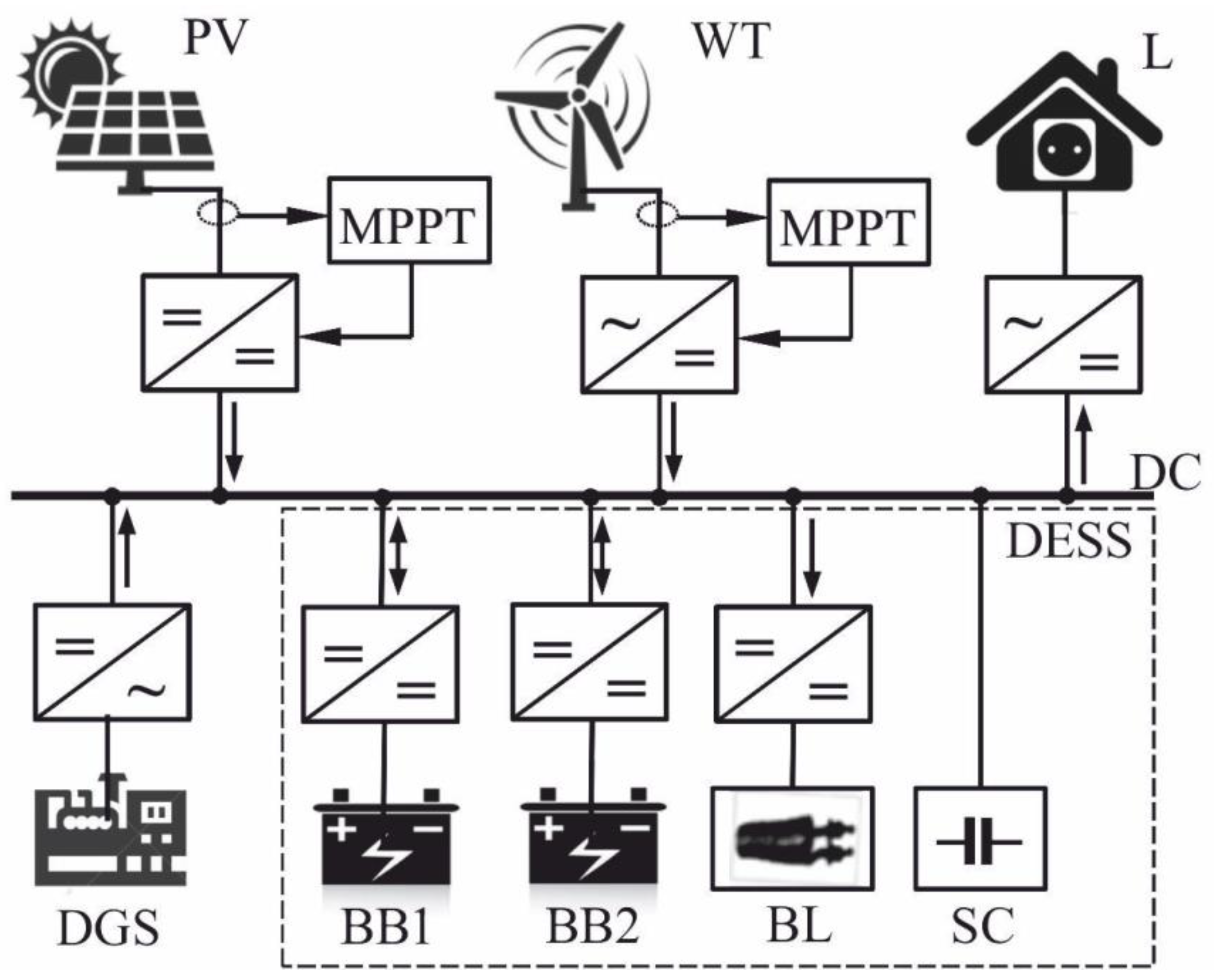
This work introduces a new technical solution that can provide the most efficient use of the RES potential and the optimization of the charge/discharge modes of BESS. The idea of the proposed solution is to use a passive voltage stabilization system on the DC bus bar by connecting a super capacitor (SC) to it and controlling the energy balance in the system using a dual-circuit energy storage system (DESS). The DESS comprises of two identical rechargeable battery bank (BB), alternately operating in charge/discharge mode, an adjustable ballast load (BL), and SC [28]. The proposed generalized HRES construction scheme is presented in Figure 1.
One of the main components of HRES with this construction method is a DC bus, which has the function of collecting and distributing electrical energy in a closed energy system.
The power balance equation for a DC bus is demonstrated by the following equation:
Generally, the power balance on the bus is determined by the current ratio of generated and consumed power. From Figure 1, it can be visualized that the possible generation sources and load power that can be used in the HESS are: Diesel generator sets (), wind power () and photovoltaic installations (), as well as discharge power BB (). Power consumers are: Consumer payload (), ballast load (), and charging power BB ().
Considering Equation (1), one may notice that, the uncontrolled variable is the amount of power consumed by the payload .
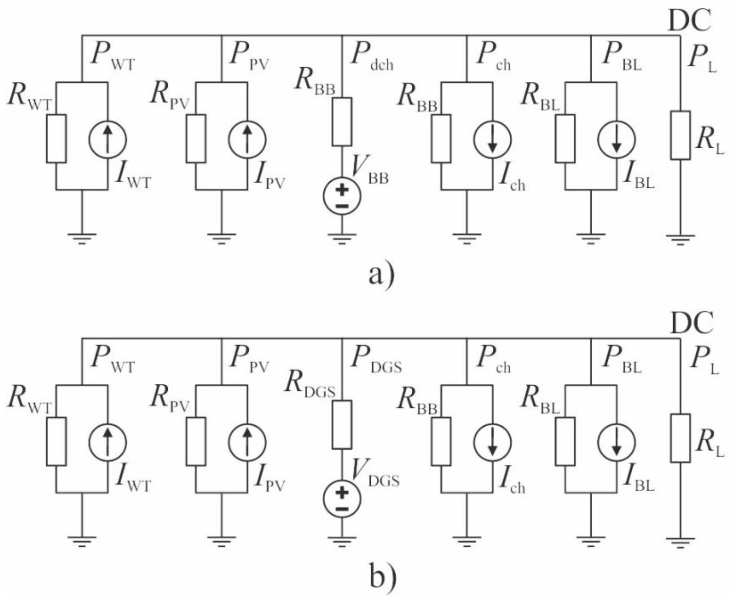
In order to achieve an optimal power transfer, from the generator to load, it is imperative to maintain both the PV and wind generators and the load at their respective optimum operating conditions (i.e., maximum power point tracking (MPPT) operations) [29,30]. Therefore, it should be observed that for ensuring the energy balance in the system, the amount of power generated and are considered unmanaged variables. To control the power balance and stabilize the DC bus voltage, the proposed control strategy involves the use of two main controlled power sources: and a battery operating in the discharge mode. Taking into account the fact that in HRES with a high penetration of renewable energy sources, modes are possible in which the amount of power generated by RES installations can significantly exceed the power consumption, the ballast load is used as an additional controlled power consumer in the system. In addition, the second BB connected to the bus in the charging power take-off mode that can be considered as a partially controlled power consumer. From Figure 2, it can be observed that simplified equivalent HRES substitution schemes are presented for the two main stabilization modes MODE1 and MODE2. In the stabilization mode MODE1 (Figure 2a), it clear that power balance control in the system is provided by the discharge BB. In addition, in the stabilization mode MODE2 (Figure 2b), the power balance is indicated by DGS. Since controlled power sources must provide stabilization of the DC bus voltage, they must operate in the mode of controlled voltage sources; all other power plants are controllable and uncontrolled current sources.
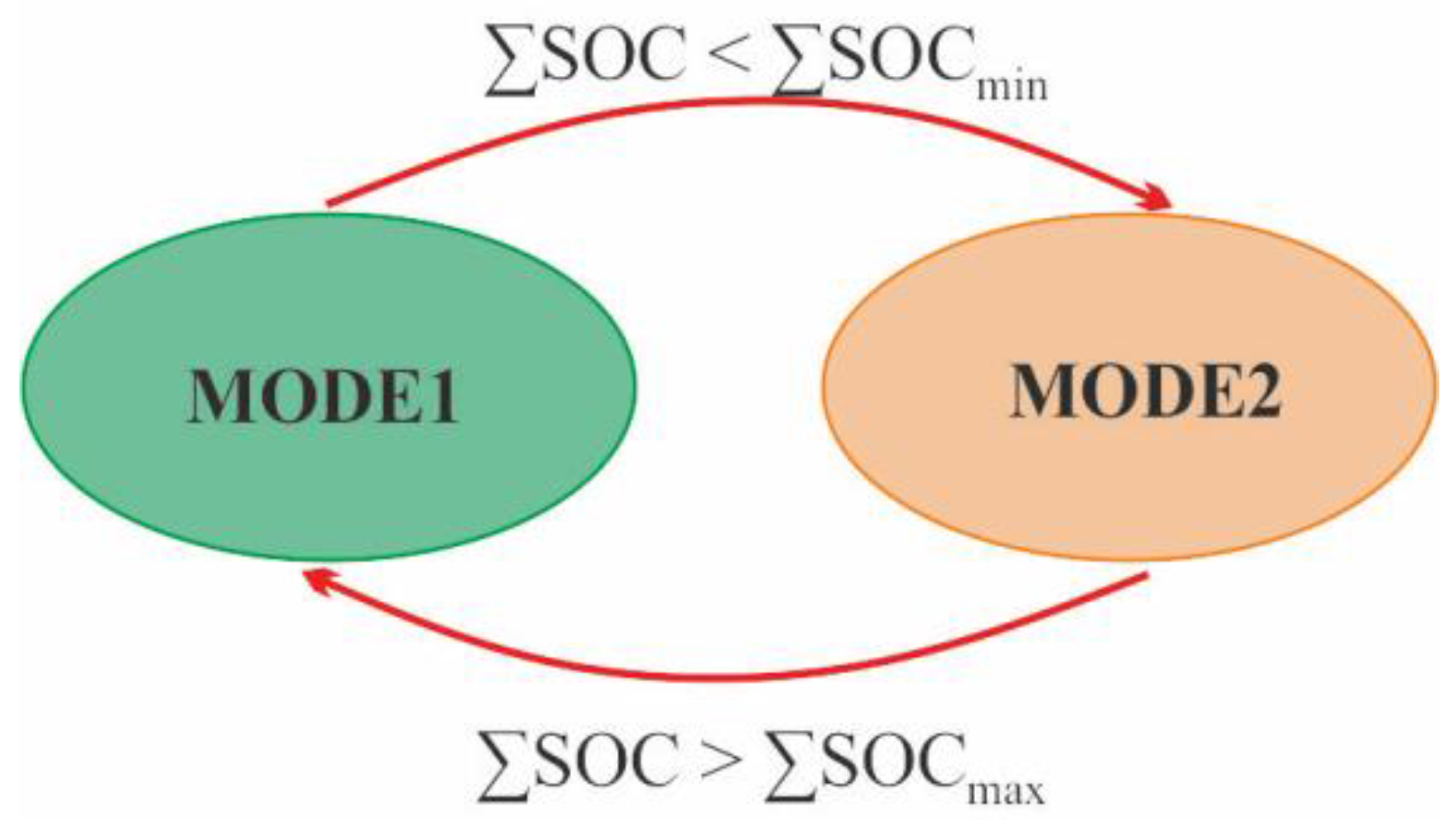
The total residual capacity value of the two BB ∑SOC is used as a criterion for changing the HRES operating modes. The transition diagram between the operating modes of HRES is schematically illustrated in Figure 3.
The present values of ∑SOCmin and ∑SOCmax are determined at the stage of the system configuration and depend on the type of BESS uses, the ratio of the main generating sources capacities, the operating conditions of the power plant, the characteristics of the consumer’s electrical load, and in general should be optimized.
In the consideration of HRES, the following values of the total residual capacity of both BBs are taken: ∑SOCmin = 125% and ∑SOCmax = 185% from their rated capacity. The choice of these values is due to the fact that the considered project uses lead-acid BESS, which necessitates limiting their maximum depth of discharge (DOD) value being 60–70% of the nominal capacity.
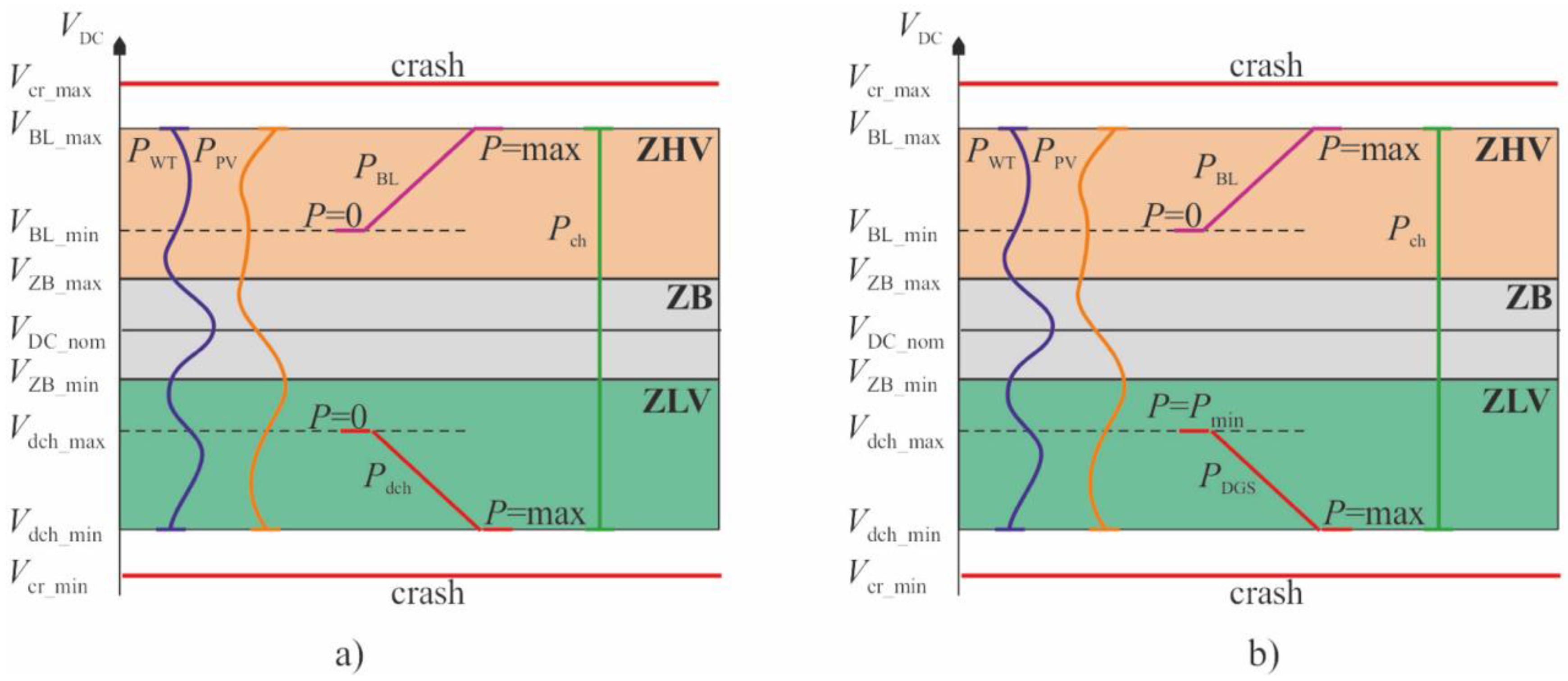
In the basic embodiment, there are three working zones of DC-bus voltage as illustrated in Figure 4: Buffer zone (ZB), high voltage zone (ZHV), and low voltage zone (ZLV). In the ZHV zone, the total power generation of the RES installations exceeds the total consumption power, and an adjustable ballast load is used as a stabilizing source in this zone in the MODE1 and MODE2 modes. Structurally, the ballast load is a set of resistors that are connected to the DC-bus through a DC-DC converter. The current value (respectively power) of the converter is regulated according to the following equation:
Equation (2) determines the linear change in power consumption of the ballast load from zero to the nominal value of in the voltage range from to . For the practical implementation of the control system by Equation (2), it is necessary to measure two electrical parameters of the mode: The voltage of the DC-bus and input current of the converter .
The red lines in Figure 4 indicates the area of accident-free functioning of the power plant. When the DC-bus voltage goes beyond the specified voltage and the operating mode of the energy system is initiated as an accident (crash), which is eliminated by means of emergency automation.
In the ZLV zone, the power consumption exceeds the total power generation of the RES installations and the stabilizing source in MODE1 mode is BB, which is operating in the discharge mode to the DC-bus as shown in Figure 4a. The current magnitude (respectively power) discharge converter BB in MODE1 is regulated according to the following formula:
Equation (3) determines the linear change in the generated power of the discharge BB from zero to the nominal value Pdch_max in the voltage range from Vdch_max to Vdch_min. This equation has been used as control input signal for the DC-bus voltage value VDC and the value of the output current of the converter Idch.
The ZB buffer zone is used to reliably separate the operating modes of control sources in the system, moreover, its use allows minimizing (ideally eliminating) the number of transitions from the ZHV zone to the ZLV zone, which can lead to an unstable or oscillatory operation mode of the control system.
In MODE2 mode as illustrated in Figure 4b, the main regulatory source of the power system is DGS. In order to preserve its operational life, it is necessary to minimize the number of connections and disconnections. In addition, in the DGS operating mode, it is necessary to ensure its loading at a level that is not less than 25% of its rated power. In the base case of the distribution of the working voltage zones for the MODE2 mode, the choice of the guaranteed charge of one BB is acceptable for consideration, and the second BB is transferred to the charge mode only after the first battery is fully charged.
In accordance with applying the algorithm of the current value (respectively power) of the DGS converter is regulated as follows:
The practical implementation of Equation (4) and the guaranteed charge of one BB during the connection of DGS provides an acceptable load factor of the diesel engine. This is achieved by limiting and retention of the DGS current that is not lower than some preset value , corresponding to the minimum permissible diesel load, for example 25% of the rated power. Technically, this requirement is realized by narrowing the control range of the output DGS converter by limiting the duty cycle value.
It should be noted that in order to implement the proposed control algorithms, it is necessary to fulfill a number of important relationships for ensuring the operation of the energy system within safe working areas as follows:
1. The value of the maximum permissible discharge power of one control BB must be higher than the maximum electrical load :
2. The nominal (maximum) value of the ballast load must satisfy the following equation:
A special case of this equation is the condition that the power of the minimum electric load is equal to zero = 0.
3. The rated power of the DGS must provide coverage for the maximum electrical load and the required charging power BB:
The idea of the proposed HRES mode control logic is to switch the BB from the charge mode to the discharge mode and vice versa according to the set threshold values of its residual capacity. Accordingly, for the practical implementation of this control logic, constant control of the residual capacity of each BB in real time mode is necessary. In addition, it is necessary to ensure control of the total residual capacity of BB ∑SOC, which is the value of the criterion for changing the operating modes of the energy system as shown in Figure 3.
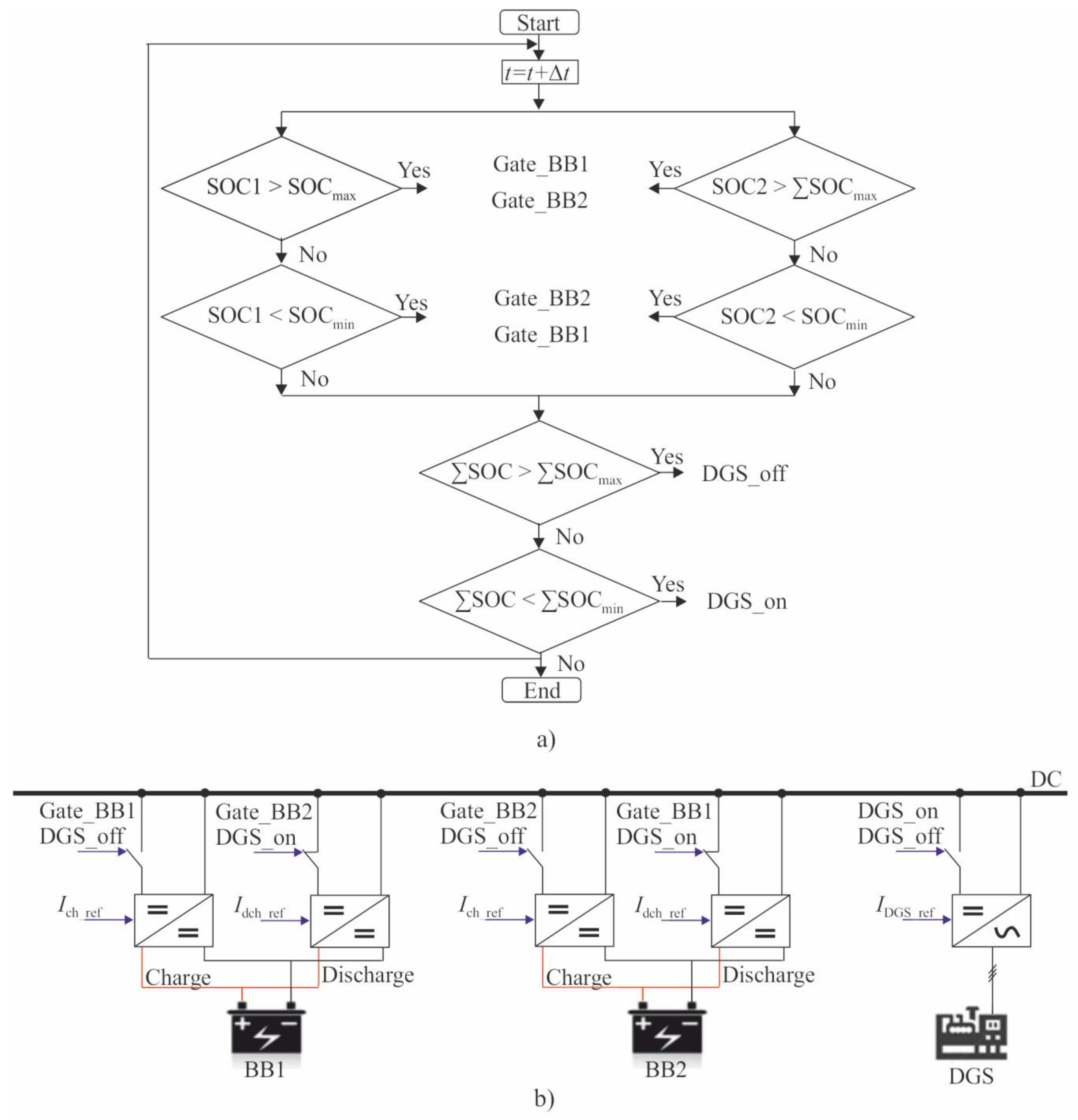
The logic of the proposed method for controlling HRES modes is explained in Figure 5, which shows the block diagram of the mode control algorithm as in Figure 5a and power circuits for connecting BESS and DGS to the DC-bus as in Figure 5b.
One of the possible options for the circuit design of the DESS controller is to separate the functions of local and strategic control of converters. The DGS converter control system can be built in a similar pattern. When applying this approach, the signals of direct control of the converter keys (, , ) are formed according to the local current loop depending on the current values of the DC bus voltage and the output (input) current of the corresponding converter and control signals, providing switching of operating modes (Gate_BB1, Gate_BB2, DGS_on/off), are formed by the logic block of the controller depending on the current values of the residual capacity BB.
In the stabilizing sources power circuit illustrated in Figure 5b, for greater clarity, the control signals generated by the controller logic block provide direct on/off BB and DGS converters due to the use of additional keys. In real schemes of constructing converters, the use of additional keys is not necessary, since the processes of switching on/off converters can be easily ensured by controlling the magnitude of the fill factor of transistors.
3. Methods and Object of Research
The MATLAB/Simulink software package (2018b, MathWorks, Natick, MA, USA) was used for this research work as the main research tool, in the environment of which, in accordance with the HRES block diagram as illustrated in Figure 1, mathematical models of all the main components of the technical system under consideration were developed and implemented. Five types of models can be distinguished as part of the comprehensive HRES model: Primary energy carrier models (wind flow and solar radiation model), power plant models (DGS, WT, and PV), storage device models (SC and BESS), energy consumer models (L (Critical Loads) and BL), and models of power semiconductor converters.
In this work, the dynamic component models that are built on the basis of equations describing the physical processes of energy conversion have been used. A detailed description of the models of HRES components that were used in the research is given by [31,32,33,34,35]. The models of components are made in the form of separating functional blocks, which makes it possible to construct and study HRES operating modes of arbitrary configuration [35].
The autonomous HRES, geographically located in the Tomsk region, consisting of WT, with a rated power of 10 kW, was accepted as the object of study in this work (Vmin = 3 м/с, Vnom = 9 м/с), PV based on a solar battery of 18 Sunway’s FSM 340M photovoltaic modules (340M, FSM, Tomsk, Russia), a Geko 20012 ED-S/DEDA diesel generator sets (340M, FSM, Tomsk, Russia), rated power 16 kW, DESS (340M, FSM, Tomsk, Russia) on the basis of 20 pieces MONBAT 12MVR200 batteries per circuit, and a super capacitor module of three in series connected supercapacitors MSK-8-112 (340M, FSM, Tomsk, Russia), with a total capacity of 2.7 F.
To simulate the HRES electrical load, a characteristic daily schedule of household loads with a maximum of 10 kW was assumed while the value of the ballast load was assumed to be 16.2 kW. The PV option has been considered with a rigidly fixed solar panel oriented to the South and installed at an angle of 56.5° to the horizon.
4. Results and Discussions
To verify the operability and approbation of the proposed technical solutions, the results of computer simulation of HRES operating modes were used. A research plan was developed, in accordance with a series of computational experiments that was carried out for simulating the static and dynamic HRES modes possibilities during its operation.
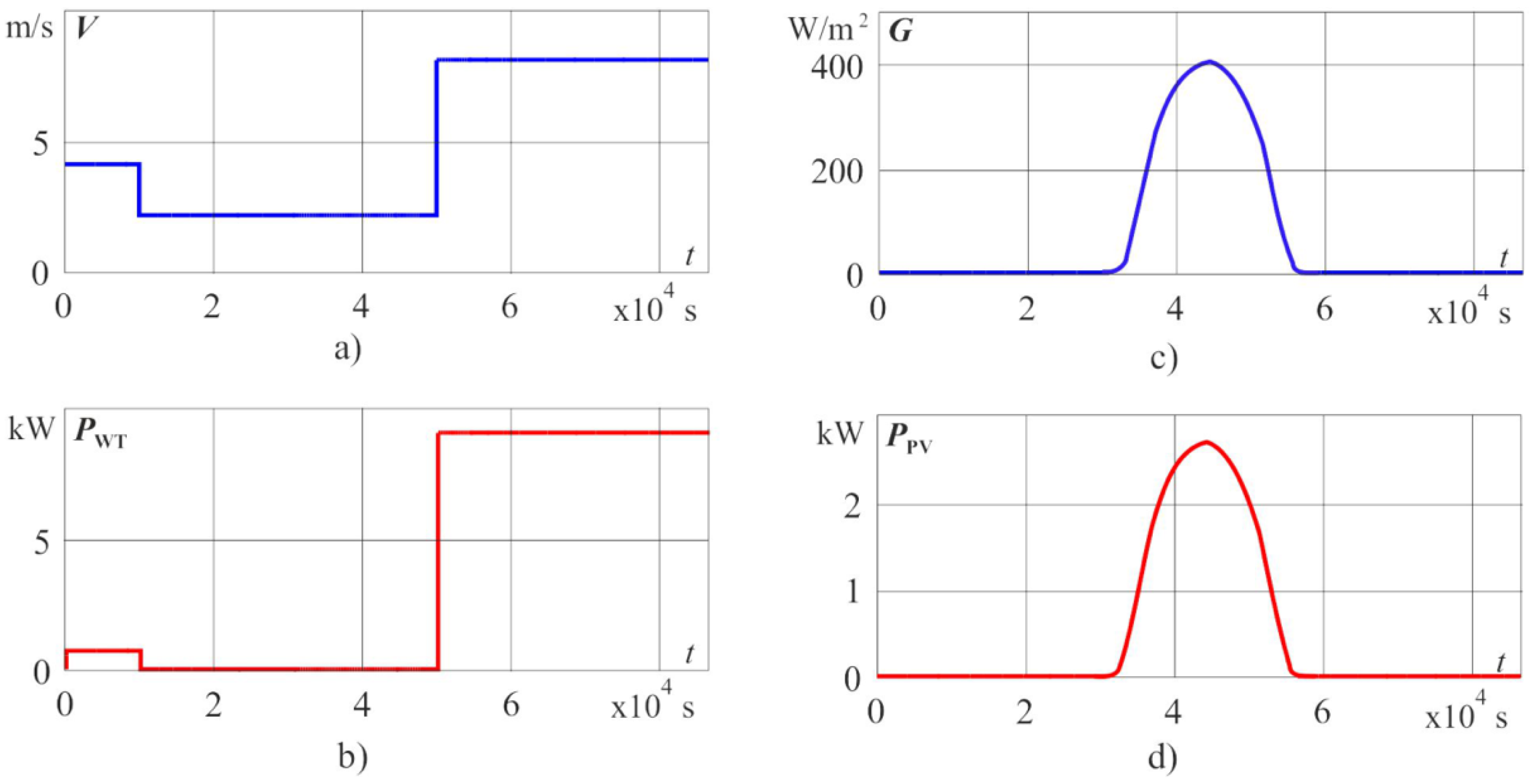
Figure 6 shows the results of modeling the electrical output of RES installations (PPV and PWT) at the daily time interval (86,400 s). Daily changes in solar radiation (G) correspond to the winter solstice with average cloud cover. Wind speed (V) is set by a step function with an amplitude of 2 m/s to 8 m/s, changing at model times of 10,000 and 50,000 s.
The explicit specification of the wind speed, which remains unchanged over long time intervals, allows us to solve two problems: On the one hand, significantly reduce the requirements for computer computing resources and thereby reduce simulation time; on the other hand, it makes the possibility to single out for the subsequent analysis that required operating modes of DESS and the entire energy system.
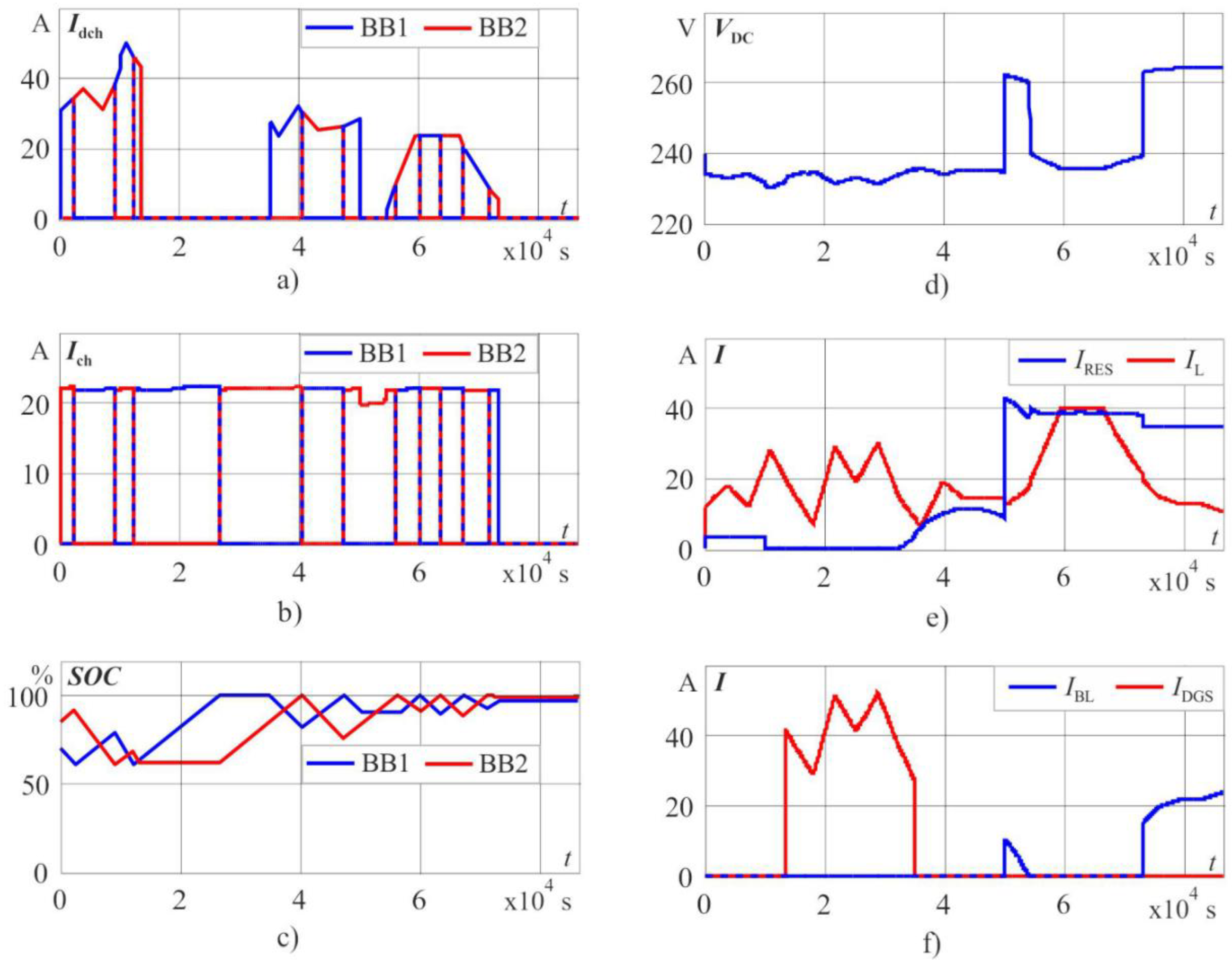
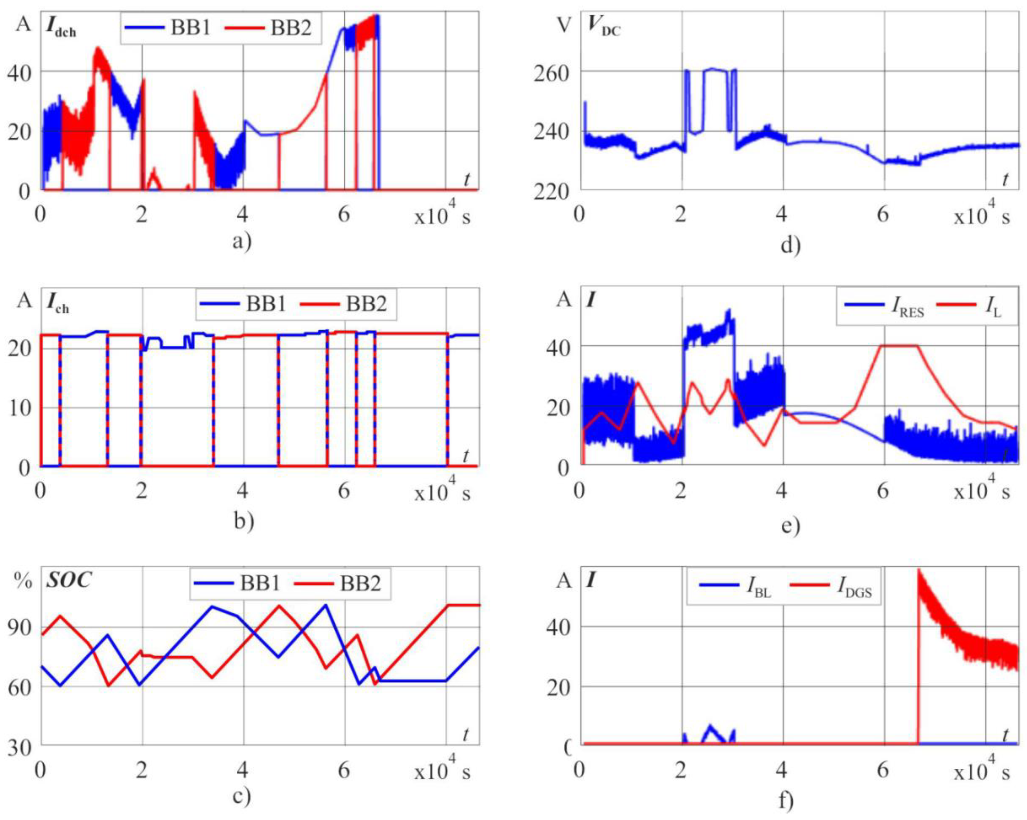
The results of HRES operating modes for the given characteristics of primary energy carriers are presented in Figure 7. This Figure shows the graphs of the change in discharge current (Idch), charge current (Ich) and residual capacity (SOC), rechargeable batteries BB1 and BB2, bus bar voltage (VDC), inflowing and outflowing currents of the DC-bus such as total current from RES installations (IRES), actual current (IL) and ballast (IBL) loads, and current DGS (IDGS).
An analysis of the obtained graphs in Figure 7 shows that the power generated by the RES installations is not enough to fully cover the electrical load in the time interval from 0 s to 50,000 s. This leads to the fact that at a time of about 14,000 s both BBs are discharged below an acceptable threshold level (∑SOC < 125%). The logic block of the controller generates a control signal to start the DGS and in the time interval from 14,000 s to 35,000 s. The power balance management in the energy system is provided by DGS. The batteries BB1 and BB2 at this interval time are alternately charged, which is clearly seen in Figure 7 from the presented graphs of their residual capacity SOC. When the total BB charge of the specified threshold level (∑SOC > 185%) is reached, the DGS is turned off and then the power balance is regulated by the discharge BB.
At intervals of model time from 50,000 s to 54,000 s and from 73,000 s to the end of the day under consideration, the generated total power by RES installations exceeds the power consumed by the payload and the recharged BB. In accordance with the specified algorithm as in Figure 4, stabilization of the energy balance in the system at these modes is ensured by controlling the power of the ballast load.
An analysis of the simulation results indicates that the proposed algorithm ensures the stable operation of the energy system in MODE1 and MODE2 modes. In addition, the DC-bus voltage does not go beyond the specified working areas and all converters operate in normal mode.
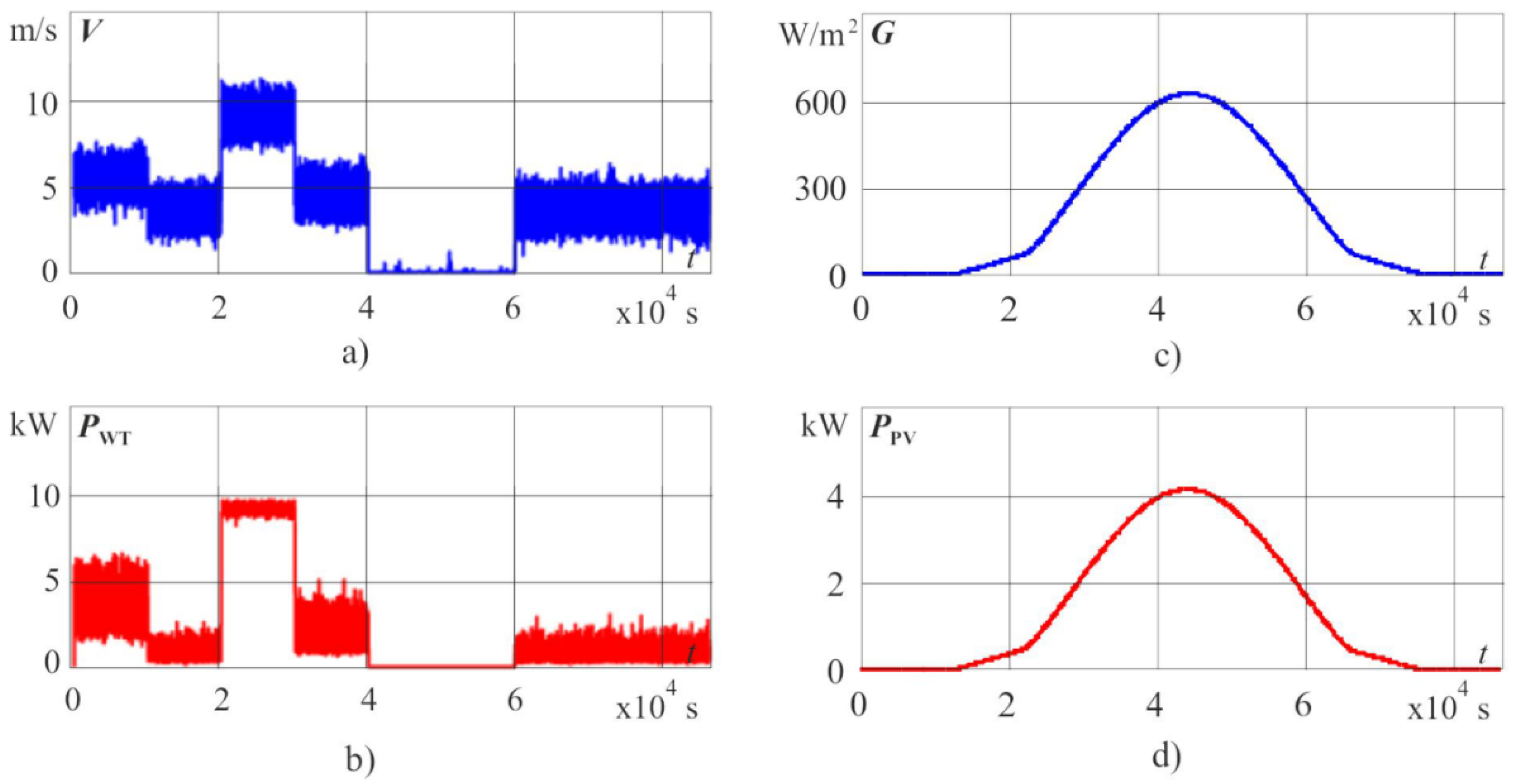
As the most complex tests for verifying the operability of the DESS control algorithm, it has been used the operating mode of the HRES daily modeling results taking into account the turbulent component of the wind speed [32]. The turbulent component of the wind flow leads to the appearance of broadband ripple of the output power WT, which can lead to a loss of dynamic stability of the energy system. However, such operating conditions are typical for HRES and their analysis is mandatory. Figure 8 and Figure 9 show the results of modeling the daily HRES operating mode taking into account the turbulent component of the wind speed.
In this computational experiment, the summer solstice is considered with average cloud cover conditions and the average wind speed during the day varies from 0 m/s to 10 m/s as shown in Figure 8, which corresponds to the entire working range of the simulated WT. From those presented graphs that shown in Figure 9, the DESS control system ensures reliable and efficient control of the power balance in an isolated energy system in all possible operating modes.
The results of the computational experiments have confirmed the operability of the proposed architecture and algorithm for managing autonomous HRES modes with the high penetration of renewable sources.
The advantages of the considered DESS control algorithm are its relative simplicity and universality. This algorithm ensures BB charge modes with a stable current and minimizes BB switching modes from charge to discharge mode and vice versa, which ensures their safety and maximum operational life.
The proposed HRES construction architecture allows the use of power semiconductor converters with inconsistent characteristics and simple circuitry. From the point of view of operational reliability, HRES is quite tenacious, since no information communication between the converters of RES installations is required, the failure of any converter or generating source, except the output inverter, does not violate the overall operability of the energy system. The simplicity of changing the system configuration is ensured by adding/excluding generating sets of various types and different manufacturers to the power plant without the need to change the control system settings.
Analysis of the annual energy balance of the HRES under consideration, geographically located in the Tomsk region, showed that the use of DESS with the proposed control algorithm provides an increase in energy production by RES installations and, consequently, an increase in energy efficiency by 28% compared to standard HRES construction methods. It should be noted that the value of this indicator largely depends on the energy potential of RES at the location of the power plant, the ratio of installed capacities and technical characteristics of the main power equipment and load, and can reach values up to 60% [36].
At present, a DESS experimental model for a rated power of 15 kW has been manufactured on the basis of battery and super capacitor modules, a set of outline design documentation, a program and methodology for its research tests have been developed. This year, it is planned to test the DESS experimental model as a part of the test bench of the local power supply system with renewable energy sources, which will assess the feasibility and effectiveness of its practical application in real power systems, verify the adopted layout decisions, and also find technical solutions to improve it designs.
5. Conclusions
This paper proposes a new construction method and an algorithm for controlling the modes of hybrid energy systems based on a dual-circuit energy storage device, which increases their reliability and energy efficiency. The paper used an isolated micro-grid in Tomsk Russia as an example to verify the effectiveness of this method. All simulations in this study have been achieved using Matlab/Simulink environment. The results of the studies showed that the proposed construction method and the HRES mode control algorithm provide reliable and efficient control of the power balance in HRES in all possible operational modes. The advantages of the proposed technical solutions are ensuring the battery charge modes with a stable current, minimizing the incomplete charge/discharge modes and efficient use of the potential of primary renewable energy.
Author Contributions
All the authors have contributed to this research. Conceptualization, S.O. and A.I.; methodology, M.A.T. and A.I.; software, Ahmed Ibrahim; validation, A.M.E.-R., M.A.T. and A.I.; formal analysis, A.I.; investigation, M.A.T., A.M.E.-R.; resources, S.O.; data curation, A.M.E.-R.; writing—original draft preparation, A.I. and M.A.T.; writing—review and editing, M.A.T. and A.M.E.-R.; visualization, A.M.E.-R.; supervision, S.O.; project administration, S.O.; funding acquisition, A.M.E.-R.
Funding
This research received no external funding.
Acknowledgments
The authors gratefully acknowledge the support offered by Tomsk Polytechnic University and the American University of the Middle East, Kuwait for this research study.
Conflicts of Interest
All of the authors declare no conflict of interest.
Nomenclature
| HRES | Hybrid renewable energy systems |
| DGS | Diesel generators sets |
| PWT | Wind power |
| PV | Photovoltaic |
| PPV | Photovoltaic power |
| WT | Wind energy |
| Pdch | Discharge power |
| HESS | Hybrid energy storage systems |
| IRES | Total current from RES |
| BESS | Battery energy storage systems |
| SC | Supercapacitor |
| VDC | Bus bar voltage |
| DESS | Dual energy storage system |
| BB | Battery bank |
| BL | Ballast load |
| MPPT | Maximum power point tracking |
| PDGS | Diesel generator sets power |
| ZLV | Low voltage zone |
| ZHV | High voltage zone |
| ZB | Buffer zone |
| PBL | Ballast load power |
| PPL | Consumer payload power |
References
- Sawle, Y.; Gupta, S.C.; Bohre, A.K. Review of hybrid renewable energy systems with comparative analysis of off-grid hybrid system. Renew. Sustain. Energy Rev. 2018, 81, 2217–2235. [Google Scholar] [CrossRef]
- Salas, V.; Suponthana, W.; Salas, R.A. Overview of the off-grid photovoltaic diesel batteries systems with AC loads. Appl. Energy 2015, 157, 195–216. [Google Scholar] [CrossRef]
- IRENA Battery Storage for Renewables: Market Status and Technology Outlook. Int. Renew. Energy Agency Abu Dhabi 2015, 32. Available online: https://www.irena.org/publications/2015/Jan/Battery-Storage-for-Renewables-Market-Status-and-Technology-Outlook (accessed on 1 December 2019).
- Eller, A.; Gauntlett, D. Energy Storage Trends and Opportunities in Emerging Markets; Navigant Consulting Inc.: Boulder, CO, USA, 2017. [Google Scholar]
- Hu, X.; Martinez, C.M.; Yang, Y. Charging, power management, and battery degradation mitigation in plug-in hybrid electric vehicles: A unified cost-optimal approach. Mech. Syst. Signal Process. 2017, 87, 4–16. [Google Scholar] [CrossRef]
- Kan, S.Y.; Verwaal, M.; Broekhuizen, H. Battery-Capacitor combinations in photovoltaic powered products. In Proceedings of the 24th International Power Sources Symposium and Exhibition 2005, Brighton, UK, 18–21 April 2005. [Google Scholar]
- Lahyani, A.; Sari, A.; Lahbib, I.; Venet, P. Optimal hybridization and amortized cost study of battery/supercapacitors system under pulsed loads. J. Energy Storage 2016, 6, 222–231. [Google Scholar] [CrossRef]
- Hund, T. Capacity loss in PV batteries and recovery procedures. Photovolt. Syst. Appl. Dep. Sandia Natl. Lab. 1999. Available online: http://citeseerx.ist.psu.edu/viewdoc/summary?doi=10.1.1.475.2472 (accessed on 1 December 2019).
- Jossen, A.; Garche, J.; Sauer, D.U. Operation conditions of batteries in PV applications. Sol. Energy 2004, 76, 759–769. [Google Scholar] [CrossRef]
- Jakhrani, A.Q.; Othman, A.; Rigit, A.R.H.; Samo, S.R. Life cycle cost analysis of a standalone PV system. In Proceedings of the 2012 International Conference on Green and Ubiquitous Technology, Jakarta, Indonesia, 7–8 July 2012. [Google Scholar]
- Ataei, A.; Nedaei, M.; Rashidi, R.; Yoo, C. Optimum design of an off-grid hybrid renewable energy system for an office building. J. Renew. Sustain. Energy 2015, 7, 053123. [Google Scholar] [CrossRef]
- Jing, W.; Hung Lai, C.; Wong, S.H.W.; Wong, M.L.D. Battery-supercapacitor hybrid energy storage system in standalone DC microgrids: Areview. IET Renew. Power Gener. 2017, 11, 461–469. [Google Scholar] [CrossRef]
- Bocklisch, T. Hybrid Energy Storage Systems for Renewable Energy Applications. Energy Procedia 2015, 73, 103–111. [Google Scholar] [CrossRef] [Green Version]
- Lahyani, A.; Venet, P.; Guermazi, A.; Troudi, A. Battery/Supercapacitors Combination in Uninterruptible Power Supply (UPS). IEEE Trans. Power Electron. 2013, 28, 1509–1522. [Google Scholar] [CrossRef]
- Narvaez, A.; Cortes, C.; Trujillo, C.L. Comparative analysis of topologies for the interconnection of batteries and supercapacitors in a Hybrid Energy Storage System. In Proceedings of the 2017 IEEE 8th International Symposium on Power Electronics for Distributed Generation Systems (PEDG), Florianopolis, Brazil, 17–20 April 2017. [Google Scholar]
- Choi, M.E.; Kim, S.W.; Seo, S.W. Energy management optimization in a battery/supercapacitor hybrid energy storage system. IEEE Trans. Smart Grid 2012, 3, 463–472. [Google Scholar] [CrossRef]
- Choudar, A.; Boukhetala, D.; Barkat, S.; Brucker, J.-M. A local energy management of a hybrid PV-storage based distributed generation for microgrids. Energy Convers. Manag. 2015, 90, 21–33. [Google Scholar] [CrossRef]
- Wu, T.; Shi, X.; Liao, L.; Zhou, C.; Zhou, H.; Su, Y. A Capacity Configuration Control Strategy to Alleviate Power Fluctuation of Hybrid Energy Storage System Based on Improved Particle Swarm Optimization. Energies 2019, 12, 642. [Google Scholar] [CrossRef] [Green Version]
- Wang, H.; Wang, T.; Xie, X.; Ling, Z.; Gao, G.; Dong, X. Optimal Capacity Configuration of a Hybrid Energy Storage System for an Isolated Microgrid Using Quantum-Behaved Particle Swarm Optimization. Energies 2018, 11, 454. [Google Scholar] [CrossRef] [Green Version]
- Nehrir, M.H.; Wang, C.; Strunz, K.; Aki, H.; Ramakumar, R.; Bing, J.; Miao, Z.; Salameh, Z. A Review of Hybrid Renewable/Alternative Energy Systems for Electric Power Generation: Configurations, Control, and Applications. IEEE Trans. Sustain. Energy 2011, 2, 392–403. [Google Scholar] [CrossRef]
- Upadhyay, S.; Sharma, M.P. A review on configurations, control and sizing methodologies of hybrid energy systems. Renew. Sustain. Energy Rev. 2014, 38, 47–63. [Google Scholar] [CrossRef]
- Sawle, Y.; Gupta, S.C.; Kumar Bohre, A. PV-wind hybrid system: A review with case study. Cogent Eng. 2016, 3. [Google Scholar] [CrossRef]
- Chauhan, A.; Saini, R.P. A review on Integrated Renewable Energy System based power generation for stand-alone applications: Configurations, storage options, sizing methodologies and control. Renew. Sustain. Energy Rev. 2014, 38, 99–120. [Google Scholar] [CrossRef]
- Gabriel Rullo, P.; Costa-Castelló, R.; Roda, V.; Feroldi, D. Energy Management Strategy for a Bioethanol Isolated Hybrid System: Simulations and Experiments. Energies 2018, 11, 1362. [Google Scholar] [CrossRef] [Green Version]
- Olatomiwa, L.; Mekhilef, S.; Ismail, M.S.; Moghavvemi, M. Energy management strategies in hybrid renewable energy systems: A review. Renew. Sustain. Energy Rev. 2016, 62, 821–835. [Google Scholar] [CrossRef]
- Augustine, S.; Mishra, M.K.; Lakshminarasamma, N. Adaptive Droop Control Strategy for Load Sharing and Circulating Current Minimization in Low-Voltage Standalone DC Microgrid. IEEE Trans. Sustain. Energy 2015, 6, 132–141. [Google Scholar] [CrossRef]
- Grigoriev, A.S.; Skorlygin, V.V.; Grigoriev, S.A.; Melnik, S.A.; Losev, O.G. A Hybrid Power Plant Based on Renewables and Electrochemical Energy Storage and Generation Systems for Decentralized Electricity Supply of the Northern Territories. Int. J. Electrochem. Sci. 2018, 90, 1822–1830. [Google Scholar] [CrossRef]
- Obukhov, S.G.; Plotnikov, I.A.; Popov, M.M.; Surkov, M.A. Self-Contained Electric Power Supply System. Patent RF No. 2638025, 2017. [Google Scholar]
- Obukhov, S.G.; Plotnikov, I.A.; Sheryazov, S.K. Methods of effective use of solar power system. In Proceedings of the 2016 2nd International Conference on Industrial Engineering, Applications and Manufacturing (ICIEAM), Chelyabinsk, Russia, 19–20 May 2016. [Google Scholar]
- Ibrahim, A.; Aboelsaud, R.; Obukhov, S. Improved particle swarm optimization for global maximum power point tracking of partially shaded PV array. Electr. Eng. 2019, 101, 443–455. [Google Scholar] [CrossRef]
- Obukhov, S.G.; Plotnikov, I.A.; Masolov, V.G. Mathematical model of solar radiation based on climatological data from NASA SSE. IOP Conf. Ser. Mater. Sci. Eng. 2018, 363. [Google Scholar] [CrossRef] [Green Version]
- Sarsikeev, Y.; Lukutin, B.V.; Lyapunov, D.Y.; Surkov, M.A.; Obuhov, S.G. Dynamic Model of Wind Speed Longitudinal Component. Adv. Mater. Res. 2014, 953–954, 529–532. [Google Scholar] [CrossRef]
- Bhandari, B.; Poudel, S.R.; Lee, K.-T.; Ahn, S.-H. Mathematical modeling of hybrid renewable energy system: A review on small hydro-solar-wind power generation. Int. J. Precis. Eng. Manuf. Technol. 2014, 1, 157–173. [Google Scholar] [CrossRef]
- Buonomano, A.; Calise, F.; D’Accadia, M.D.; Vicidomini, M. A hybrid renewable system based on wind and solar energy coupled with an electrical storage: Dynamic simulation and economic assessment. Energy 2018, 155, 174–189. [Google Scholar] [CrossRef]
- Obukhov, S.G.; Plotnikov, I.A. Simulation model of operation of autonomous photovoltaic plant under actual operating conditions. Bull. Tomsk Polytech. Univ. Geo Assets Eng. 2017, 6, 38–51. [Google Scholar]
- Sheryazov, S.K.; Shelubaev, M.V.; Obukhov, S.G. Renewable sources in system distributed generation. In Proceedings of the 2017 International Conference on Industrial Engineering, Applications and Manufacturing, ICIEAM, St. Petersburg, Russia, 16–19 May 2017. [Google Scholar]
Figure 1.
Block diagram of a hybrid power plant with dual-circuit energy storage.

Figure 2.
Simplified equivalent circuits of substitution of the hybrid power system. (a) Stabilization mode MODE1; (b) Stabilization mode MODE2.
Figure 2.
Simplified equivalent circuits of substitution of the hybrid power system. (a) Stabilization mode MODE1; (b) Stabilization mode MODE2.

Figure 3.
Transition between modes of stabilization.

Figure 4.
Basic case of voltage zones distribution: (a) battery stabilization mode and (b) stabilization mode from diesel generator sets.
Figure 4.
Basic case of voltage zones distribution: (a) battery stabilization mode and (b) stabilization mode from diesel generator sets.

Figure 5.
Logic of proposed method for controlling the modes of the hybrid energy system: (a) flow chart of the control algorithm and (b) power circuits of the stabilizing sources.
Figure 5.
Logic of proposed method for controlling the modes of the hybrid energy system: (a) flow chart of the control algorithm and (b) power circuits of the stabilizing sources.

Figure 6.
Simulation results of the output power of the renewable energy installations on the daily time interval: (a) wind speed; (b) wind power capacity; (c) solar irradiance; and (d) solar power.
Figure 6.
Simulation results of the output power of the renewable energy installations on the daily time interval: (a) wind speed; (b) wind power capacity; (c) solar irradiance; and (d) solar power.

Figure 7.
Simulation results of operating modes of a hybrid energy system on the daily time interval: (a) battery discharge current; (b) battery charging current; (c) residual battery capacity; (d) bus bar voltage; (e) total current of renewable energy installations and load current; and (f) ballast current and diesel generator sets current.

Figure 8.
Simulation results of the output power of the renewable energy installations on the daily time interval: (a) wind speed; (b) wind power capacity; (c) solar irradiance; and (d) solar power.
Figure 8.
Simulation results of the output power of the renewable energy installations on the daily time interval: (a) wind speed; (b) wind power capacity; (c) solar irradiance; and (d) solar power.

Figure 9.
Simulation results of operating modes of a hybrid energy system on the daily time interval: (a) battery discharge current; (b) battery charging current; (c) residual battery capacity; (d) bus-bar voltage; (e) total current of renewable energy installations and load current; and (f) ballast current and diesel generator sets current.

© 2019 by the authors. Licensee MDPI, Basel, Switzerland. This article is an open access article distributed under the terms and conditions of the Creative Commons Attribution (CC BY) license (http://creativecommons.org/licenses/by/4.0/).
Share and Cite
MDPI and ACS Style
Obukhov, S.; Ibrahim, A.; Tolba, M.A.; El-Rifaie, A.M. Power Balance Management of an Autonomous Hybrid Energy System Based on the Dual-Energy Storage. Energies 2019, 12, 4690. https://doi.org/10.3390/en12244690
AMA Style
Obukhov S, Ibrahim A, Tolba MA, El-Rifaie AM. Power Balance Management of an Autonomous Hybrid Energy System Based on the Dual-Energy Storage. Energies. 2019; 12(24):4690. https://doi.org/10.3390/en12244690
Chicago/Turabian StyleObukhov, Sergey, Ahmed Ibrahim, Mohamed A. Tolba, and Ali M. El-Rifaie. 2019. "Power Balance Management of an Autonomous Hybrid Energy System Based on the Dual-Energy Storage" Energies 12, no. 24: 4690. https://doi.org/10.3390/en12244690
Note that from the first issue of 2016, this journal uses article numbers instead of page numbers. See further details here.