Energy-Saving Hot Open Die Forging Process of Heavy Steel Forgings on an Industrial Hydraulic Forging Press


Department of Manufacturing Engineering and Metrology, Kielce University of Technology, 25-314 Kielce, Poland
*
Author to whom correspondence should be addressed.
Energies 2020, 13(7), 1620; https://doi.org/10.3390/en13071620
Submission received: 1 March 2020
/
Revised: 24 March 2020
/
Accepted: 25 March 2020
/
Published: 2 April 2020
(This article belongs to the Section B: Energy and Environment)
Abstract
:The study deals with the energy-saving process of hot open die elongation forging of heavy steel forgings on an 80 MN industrial hydraulic forging press. Three innovative energy-saving power supply solutions useful for industrial hydraulic forging presses were analyzsed. The energy-saving power supply of hydraulic forging presses consists in reducing electricity consumption by the electric motor driving the pumps, reducing the noise emitted by pumps and reducing leaks in hydraulic piston cylinders. The predicted forging force as a function of heavy steel forging heights for various deformation temperatures and strain rates was determined. A simulation model of the 80 MN hydraulic forging press is presented, which is useful for determining the time-varying parameters during the forging process. An energy-saving control for the hydraulic forging press based on the forging process parameters’ prediction has been developed. Real-time model predictive control (MPC) was developed based on multiple inputs multiple outputs (MIMO), and global predictive control (GPC). The GPC has been implemented in the control system of an 80 MN industrial hydraulic forging press. The main advantage of this control system is the repeatability of the forging process and minimization of the size deviation of heavy large steel forgings
1. Introduction
Along with the development of the energy industry and the growing power of power engineering devices, the demand for large-sized hot-forged products has increased, which include turbine shafts (water, gas, steam), rotors for wind, and gas power generators. Free forging is the oldest forging method that is used to forge heavy charge materials in short production runs. Forged heavy, large, steel forgings find buyers mainly in the shipbuilding, machinery, energy and metallurgy industries. High-pressure hydraulic forging presses are used for open die forging of heavy steel forgings (carbon, alloy, high-alloy, stainless and other steels). The forecast of the Forging Industry Association (FIA) regarding the steady increase in demand for forgings used in the power engineering and oil industries was confirmed at the 20th International Forgemasters Meeting (IFM’2017) in Austria. Furthermore, based on data from EUROFORGE (an organization that associates European production associations, including the Polish Forge Association), the volume of forged products has been growing steadily, and in 2020 it will reach over 10 million tonnes. The global forging market is likely to grow significantly at a CAGR (Compound Annual Growth Rate) of close to 8%, reaching USD 111.1 billion by 2020, according to Technavio’s latest report [1]. Due to the demand for large-size forged products for the nuclear and wind energy sectors, heavy hydraulic open die forging presses with a force of over 100 MN have been built in the last 10 years, including Japan Steel Works 140 MN (Japan), Doosan 170 MN (South Korea), Shanghai 165 MN (China), Sheffield Forgemasters 150 MN (Great Britain), Vítkovice 120 MN (Czech Republic), OMZ Izhora 150 MN (Russia), and WepukoPahnke 200 MN (Germany) [2].
The literature was reviewed for heavy forging, i.e., elongation forging of heavy, large steel forgings on a high-pressure hydraulic forging press. No research papers have dealt with the control of hydraulic forging presses in industrial conditions. Most of the papers concern material issues, such as ingot deformation, elimination of non-metallic inclusions, and voids in forgings. Ref. [3] describes the analysis of the three-dimensional stress and strain state for the process of elongation forging of X37CrMoV51 die steel using the finite element method. Ref. [4] specifies real-time derivation of the actual spread coefficient for a given workpiece as it is being formed. In Ref. [5], loads of the aluminum forging process were estimated during the isothermal steady-state process using a reliable, fast and inexpensive software tool. In Ref. [6], the slab method analysis was used to create simple forging simulation tools. There has been little research work on the models, simulation and examination of hydraulic forging presses. Ref. [7] presents a collection of works on the modelling, analysis, and control of hydraulic actuators for forging. Ref. [8] concerns the momentary forming process on a hydraulic press, in which by measuring the curves of the forming stroke and pressure it is possible to predict the forging process using real-time parameter approximation. A prediction model calculates the dimensions of forgings that can be achieved at present. The theoretically calculated results were confirmed using a model calculation and in tests on a trial hydraulic press plant. A precise backpropagation (BP) neural network based on an online model predictive control (MPC) strategy is proposed to control the time-variant and nonlinear forging process on a 4000T hydraulic press machine in the study [9]. The basic idea of Ref. [10] was to develop process models that would combine data from online measurements and a simplified plastomechanical model for the forecasting of the equivalent strain rate and the temperature in the core of the part being forged. In Ref. [11], the theoretical minimum and actual specific energy consumption (SEC) of the typical steel manufacturing process (SMP) were studied.
The Forged Products Division (FPD) of CELSA Huta Ostrowiec (CHO), the CELSA GroupTM steel plant in Poland, is a fully integrated facility that enables the whole production process to be conducted in-house, including steel melting, forging, heat treatment and machining [12]. The most common are forged heavy components weighing from 1000 kg to 80,000 kg, with a length of up to 22 m and a diameter of up to 2.4 m, made of constructional carbon steel, low-alloy, and medium-alloy steel. These elements are intended for the power industry (turbine drive shafts), shipbuilding (monolithic and folding crankshafts for marine engines), metallurgy (metallurgical rollers) and mining industries (rings, sleeves, etc.).
This study deals with the novel energy-efficient power supply and intelligent control system of an industrial hydraulic forging press for the elongation forging of heavy large steel forgings. An important contribution of this study is to present how to go from predicting the parameters of the hot open die forging process to the control parameters of the industrial hydraulic forging press to produce good quality heavy large steel forgings, leading to a reduction in electricity consumption, a reduction in gas consumption, and a reduction in noise emitted by pumping systems, as well as savings in working fluid (water). Such solutions can be used in different steel production processes (SMP). The presented factors of energy consumption can help in other research in the steel industry in assessing energy savings. This research article provides knowledge of the process of forging heavy and large forgings, which is usually limited to specialists in industrial practice.
2. Energy-Saving Power Supply for 80 MN Hydraulic Forging Presses
Innovative energy-saving solutions useful for power supplying 80 MN hydraulic open die forging presses were analyzed. Comparative analysis showed that there are solutions available on the market in the field of hydraulic press power supply systems, offered by the manufacturers WepukoPahnke, Oilgear, Hauhinco, Inoxihp, Schäfer&Urbach, and SMS Meer. However, the disadvantage of these solutions is the lack of possibility to control the pressure of the hydraulic press in several operations. The use of innovative energy-saving power supplies for hydraulic open die forging presses gives the benefits of reduced electricity consumption by the electric motor driving the pumps, reduced noise emitted by the pumps, and reduced leaks in hydraulic cylinders.
Three innovative energy-saving power supply solutions useful for industrial hydraulic forging presses were analyzed.
- In the first solution, shown in Figure 1, the multiplier pump system was analyzed according to the OILGEAR concept, in which a one piston oil pump and two oil/water piston multipliers were used. This solution has the advantages of both an oil hydraulic drive and a water hydraulic drive. The hydraulic oil pump gives greater possibilities for controlling hydraulic parameters. In multipliers, the energy is transformed from a regulated pump system (oil system) into the water supply system to the plunger cylinder of the hydraulic forging press. The advantage of multiplier plunger drives is minimal pressure pulsation, which has a significant impact on the accuracy of the forging process.
- The second solution, shown in Figure 2 based on the WEPUKO concept, presents a set of pumps connected in series and in parallel. The supply system uses one non-adjustable axial piston pump and two parallel-connected high-pressure radial pumps with servo control. The servo-controlled pumps supply the main cylinder of the hydraulic forging press directly, which results in low-pressure drop and high efficiency of the supply system. The servo-controller adapts the pressure and capacity of the pumps to the instantaneous forging force. Such solutions allow us to increase the frequency of the work cycle and thereby reduce production costs.
- In the third own solution, shown in Figure 3, two parallel supply circuits are introduced: one supply circuit is based on unregulated three-piston pumps with a pressure of 32 MPa and high capacity 2000 L/min; the second supply circuit is based on a regulated radial pump with a pressure of 42 MPa and a capacity of 500 L/min. Such a solution is most useful for the power supply of the hydraulic forging press of 80 MN at the FDP, because it will optimize the forging process, especially in the case of heavy, difficult-to-deform forgings requiring high forging/deformation force.
One of the main goals of this research was to reduce the energy consumption and life cycle costs of 80 MN hydraulic open die forging press by means of an efficient, environmentally friendly and innovative energy-saving power supply. The existing hydraulic power supply with triplex pumps has been compared with an energy-saving solution based on a parallel connection of variable pumps. The comparison of both solutions is based on the operating data listed in Table 1 and the technical data listed in Table 2.
Based on the above data, it was possible to determine the reduction of annual energy costs by approximately €218,917 and reduce annual maintenance costs by approximately €123,911. The advantages of using an innovative power supply system for hydraulic forging presses lead to a reduction in noise emitted by pumping systems to 80 dB. Adjusting the working pressure to the forging press load contributes to water savings by up to 10% by reducing leakage through the seals around the cylinders.
3. The Predictive Model of the Elongation Forging Process
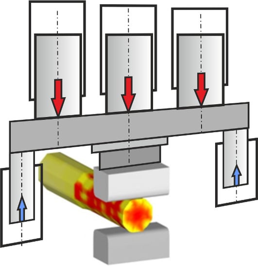
The process of hot open die forging, during which the forgings are elongated, is analyzed. The elongation forging operation is carried out by putting the ingot reheated to the forging temperature on the lower die and pressing with the upper die [13]. Afterwards, the ingot is turned 90° and pressed again. Two drafts with simultaneous rotation of 90° are called a single forging pass. The geometry of the elongated forgings is shown in Figure 4.
Initial forging dimensions: height h0, width w0 and length l0. Forging dimensions with a single draft: height h1, width w1 and length l1. The average forgings width w1 and forgings length l1 with a single draft will be given as [4]:
where a is the value of the spreading coefficient determined experimentally by Tomlinson and Stringer [14], which was adapted to the empirical model via the equation [15]:
where the value b0 represents the initial bite, i.e., the length of the forging in contact with the dies.
The contact surface A1 of the forging with the dies after a single draft:
Between the die and the forgings, the following are taken into account: contact surface, friction and heat transfer. These phenomena were described by Siebel according to the following formula [16]:
where μ is the coefficient of friction stress on the die surface during hot forging (μ = 0.3), k is the deformation strengthening indicator (k = 1.12), and Δh is the reduction of forging height, Δh = h0–h1.
The stress–strain curves describing the deformation behavior of the dendritic microstructure of the cast ingot were analyzed in terms of the Arrhenius and Hansel-Spittel models, which were implemented in Forge software [17]. Based on [18], the simplified Hensel-Spittel model was adopted, which describes the predicted hot flow stress related to the start of dynamic recrystallization (DRX):
where m0 = 1200 MPa, m1 = −0.0025, m2 = −0.0587, m3 = 0.1165, m4 = −0.0065 are the predicted material constants of C45 steel after nonlinear regression analysis of the experimental data using FORGE software, T is the deformation temperature, φ is the true strain in the direction forging height, is the strain rate, and v is the die speed corresponding to the strain rate .
The model of predicted forging/deformation force Fd(h) as a function of forging height h for a single draft has the following form:
The flow stress σ1 and forging/deformation force Fd was determined for a single draft when the forgings dimensions are: h0 = 0.5 m, w0 = 0.2 m, h1 = 0.4 m, b0 = 0.1 m, Δh = h0 – h1 = 0.1 m, εh = Δh/h0 = 0.2. The selected deformation temperature range of T = 900 1200 °C and the strain rate range of = 0.0110 s−1 were used to create stress-strain and force deformation curves.
4. Modelling and Simulation of the Forging Process on a Hydraulic Forging Press
The hydraulic forging press with a force of 80 MN is intended to produce blocks, shafts, cylinders, shells and other parts made of carbon and alloyed steel, titanium and non-ferrous alloys. The hydraulic press contains a vertical structure with the arrangement of the main cylinders in the top, driven by pump-accumulator stations. The press structure consists of stationary cross-rails—the frame and the crown are interconnected through the columns over which the ram travels. The water-hydraulic power system consists of 11 stations of double-set pumps and accumulators. During the idle motion of the hydraulic press (without any useful work), the energy stored in the accumulators is used. Then, during the working motion, the hydraulic press is powered by high-pressure from the pump station. When the set pressure is reached, the discharge valve switches automatically to the idle motion. In the working cycle, the power of the hydraulic press is always at the maximum level, regardless of the force of the deformation of the forging. A diagram of the hydraulic forging press with a force of 80 MN simulating the forging process is shown in Figure 7.
A dynamic analysis of the 80 MN hydraulic forging press was carried out for its working and return movement. The beginning of the press movement was considered to start from the moment of contact of the upper die with the forgings. In the initial state, the coordinates of the press movement are plunger displacement y(0) = 0 and plunger speed dy(0)/dt = 0. Meanwhile, the initial pressure p10 in the working cylinder and the initial pressure p20 in the return cylinder were determined as follows [19]:
where α is the area ratio, α = (2A2)/(3A1), pS is the supply pressure, pL is the initial load pressure, pL = (mg − Ft)/(3A1).
Equation of the hydraulic press working motion “y+”:
Equation of the hydraulic press return motion “y-”:
where m is the mass of moving parts, b is the viscous damping coefficient, Ft is the sliding friction force at the cylinder seals and guide pillar, g is the gravitational acceleration, and Fd is the forging /deformation force Equation (9).
ΣFh1 is the sum of hydrostatic forces in the working cylinders,
where D1 is the diameter of the working plunger, A1 is the effective area of the working plunger, and p1 is the pressure in the working cylinder.
ΣFh2 is the sum of hydrostatic forces in the return cylinders,
where D2 is the diameter of the return plunger, A2 is the effective area of the return plunger, and p2 is the pressure in the return cylinder.
Pressure equations during the working motion:
Pressure equations during the return motion:
where K is the bulk modulus, V1, V2 are the volumes of the chambers in the working and return cylinders, and kl1, kl2 are the coefficients of external leakage flow in the working and the return cylinders.
Flow rates qvPB, qvAT, qvPT, and qvPA through the directional control valve (see Figure 7):
where Cd is the valve discharge coefficient, ρ is the density of oil, AvPB(z), AvAT(z), AvBT(z) and AvPA(z) are the flow cross-sectional areas of the directional valve, depending on the opening (displacement z of valve spool), and pT is the return pressure in a tank.
The dynamic model of the directional control valve was adopted as a first-order inertial element:
where T1 is the time constant of the PT1 element, and kz is the product of the gain factor and the input signal, kz = K1u.
The following constant parameters were introduced to the dynamic simulation of the hydraulic forging press: m = 90,000 kg, b = 25,000 Nsm−1, Ft = 200,000 N, pSmax = 32 MPaD1 = 0.6 m, D2 = 0.5 m, Avimax = 0.01 m2, K = 22109 Pa, V10 = 0.3 m3, kw1 = 810−13 m3s−1 Pa−1, kw2 = 1410−14 m3s−1Pa−1, V20 = 0.1 m3. Simulation tests were carried out for single-pass forging, during which the forging height is reduced by Δh = h0–h1 = 0.1 m. The characteristics of the degree of opening of the directional control valve are shown in Figure 8.
5. Energy-Saving Control of the Hydraulic Forging Press
The energy-saving control system of a hydraulic forging press takes into account the three phases of the operating process: the drop of the upper die to make contact with the forging; the forging deformation process; the return of the upper die to the initial position after decompression of the working cylinder. The prediction of the forging process parameters was the basis for developing an energy-saving control algorithm of the 80 MN hydraulic forging press for forging difficult-to-deform forgings. The operation of predictive algorithms is based on the use of knowledge about the prediction of forgings deformation to determine the parameters of forging process control. A diagram of the real-time model predictive control (MPC) of the process parameters of hot open die forging on the 80 MN hydraulic forging press is shown in Figure 11.
The MPC of the forging process was developed for selected operational data/parameters, such as forging force and forgings deformation, which will assist process planners and process operators in making decisions [20]. Before selecting the parameters of the forging process, a simulation assessment of the hydraulic forging press control was carried out. The MPC controller solves optimization problems at each instant of time through three essential elements: prediction model, objective function and control law. The MPC controller was implemented in the control system of the hydraulic forging press, which, as a result of the actual measured forging parameters—the displacement y(t) of the traverse (including the phase of reducing the height h(t) of deformed forgings) and the load pressure p(t) in the working cylinder (corresponding to the deformation force Fd of the forgings)—generates the input signal u(t) to the control valve (CV). Meanwhile, the forging temperature T is measured only at the beginning of the forging process, on which the correct deformation of forgings depends. A block diagram of the structure of an MPC for a hydraulic forging press is shown in Figure 12.
Using multiple MPCs enables switching between two controllers in real time based on the current conditions; it is a switchable model. The control algorithm receives two reference trajectories rh(t) and rp(t), and two measured values: yh(t) from the position transducer and yp(t) from the pressure transducer. Trajectories of reference parameters (the displacement rh(t) = yref(t) and load pressure rp(t) = pref(t),) are shown on the computer panel (Figure 13), which shows the three phases of the operating process taken into account in the control of the hydraulic forging press.
The global predictive control (GPC) algorithm uses the object model in the form of a discrete CARIMA (Controlled Auto-Regressive Integrated Moving-Average) [21], which can be quite easily used in the forging process. The CARIMA model is the standard form used for predictive controller design, because it is used to obtain good output predictions and optimize the sequence of future control signals to minimize the multistage function defined over the prediction horizon [22]. For future (predicted) values to be available, the forging process model must be considered, which relates the controlled outputs yh(k) and yp(k) with the increments of input signals: Δuh(k), Δup(k), as well as with non-measurable random disturbance ξh(k) and ξp(k).
The multiple CARIMA representing the MIMO model of the hydraulic forging press takes the following form:
where , , , , , are the polynomials in the backward shift operator , and d is the dead time of the system, Δ = 1 − z−1.
For simplicity, , polynomial in Equation (17) is chosen to be 1, then the other polynomials are [23]:
The polynomials Ah(z−1) and Ap(z−1) were parameterized by the vectors:
Figure 14 shows the identified polynomial parameters (18) of the predictive model limited for na = 3.
The optimal criterion is used in the GPC algorithm, which is an objective function written as a quadratic “cost” function. With the multiple GPC, the objective functions have the following form:
where h(k+i) and p(k+i) are the predictive (future) outputs, rh(k+i) and rp(k+i) are the reference trajectories of the output parameters, Δuh(k+i) and Δup(k+i) are the incremental predictive inputs, Hp is the predictive horizon (Hp ≥ 1) and Hc is the control horizon (1 < Hc ≤ Hp), and λh(i) and λp(i) are the weighing factors.
Constraints in the outputs and inputs:
The predictive output (controlled variable prediction) and are written in vector/matrix form:
where and are the matrices of future increments of control signals vectors Δuh and Δup, eh and ep are the error (white noise) vectors.
Solutions (21) and (22) for increments of control signals Δuh and Δup can be presented in the following form:
Equation (24) have been rewritten into the final form:
where , .
MPC is an optimization control method that uses the current state and a predictive model to obtain the optimal input vector by solving an optimization problem [24]. The goal of the MCP algorithm is to minimize the difference between the expected (predicted) forging parameters and the reference forging parameters. Therefore, the objective function (22) is minimized:
By optimizing the objective functions in the finite control horizon Hc the optimal control signals and were determined. Figure 15 shows the increments of the optimal control signals Δuh (a) and Δup for Hc = 4.
The reference output signals trajectories: rh = href(t) and rp = pref(t), and predictive output signals trajectories: h = h(t) and p = p(t) for optimal input signals: h and p are shown in Figure 16.
Predictive algorithms were used to predict the forging process based on the application of knowledge about future forging parameters to determine the current values of control parameters. The use of the prediction control system for the industrial hydraulic forging press gives greater possibilities to shape heavy, large steel forgings in the open die forging process. The main advantage of this manufacturing technique is the repeatability of the forging process and the minimization of forgings’ size deviations. The forging process can be executed with maximum accuracy and cost-effectiveness.
The use of the energy-saving control made it possible to optimize the forging force and increase the frequency of the hydraulic press cycle. As a result, a greater degree of deformation of forgings and reduce the time of forging operations, including inter-operative heating, was achieved. When the temperature of forgings declines below the required level, intermediate reheating is necessary. For heavy large forgings this process is repeated several times. Reducing the number of intermediate reheating operations results in a decrease in gas consumption, which increases the energy efficiency of the forging operation and is environmentally advantageous.
As part of the pilot programme on the energy-saving hot open die elongation forging process, several heavy steel forgings weighing from 2000 kg to 50,000 kg were made. Energy and gas consumption, as well as carbon dioxide emissions, were analyzed after each forging process. Specific energy consumption (SEC) in kilowatt-hours per tonne of forging steel (kWh/t) or megajoules per tonne of forging steel (MJ/t) was used to assess the energy efficiency of the forging process:
where EC is the energy (gas) consumption, and FM is the forgings mass.
For natural gas, the gas consumption in m3 to kWh conversion is used. The carbon dioxide (CO2) emission intensity (EI) was defined as the quantity of carbon dioxide per tonne of forging steel (kgCO2/t):
where CDE is the carbon dioxide emission conversion factor in kgCO2/kWh, in Poland CDE = 0.773 kgCO2/kWh amount.
Table 3 compares the total reduction of specific energy consumption (SEC) and carbon dioxide emission intensity (EI) after entering the energy-saving hot open die forging process of heavy steel forgings on an industrial hydraulic forging press.
6. Conclusions
The developed energy-saving control of the industrial hydraulic forging press allows for shaping forgings with the prediction of forging parameters. Increasing the force and frequency of forging makes it possible to achieve a greater degree of deformation of the forgings, as well as reducing the time of forging operations by decreasing the amount of inter-operative heating. This is particularly important when forging heavy large forgings. The use of the energy-saving control allows for maximally accurate forging geometry, which minimizes material allowances and reduces material consumption in production. Further benefits include the reduction in the number of intermediate reheating operations, which results in the reduction of gas consumption and increases the energy efficiency of forging, which has a positive impact on the environment. The implementation of the presented research project contributed to the reduction of electricity consumption due to the implementation of new solutions in the field of power supply and control of the hydraulic forging press, as well as the reduction of gas consumption for heating furnaces due to the reduction of the amount of inter-operative heating. The advantage of the proposed predictive forging technology is a positive impact on sustainable development and the environment. As a result of the predictive control implementation, significant improvements were made in the quality and strength parameters of forgings compared to those available on the international market, including, among other things, a homogeneous internal structure free of discontinuities; correct fibre arrangement in steel; tensile strength at the level of min. 1000 MPa; yield point at the level of min. 800 MPa; grain size at the level of min. 6μm.
Author Contributions
Conceptualization, methodology, writing—original draft preparation, writing—review and editing, software; supervision, visualization: R.D.; validation, investigation, data curation: P.W. All authors have read and agreed to the published version of the manuscript.
Funding
This research received no external funding.
Acknowledgments
This work was carried out in cooperation with the Forged Products Division (FPD) of CELSA Huta Ostrowiec (CHO), the CELSA GroupTM steel plant in Poland, in the realization of the research project POIR.01.01.02-00-0163/16 “Demonstration of free forging technology for large-size hardly deformable forgings with the use of an innovative energy-saving power supply system and intelligent control of hydraulic presses in real-time” supported by the National Centre for Research and Development in Poland within the framework of the Smart Growth Operation Programme 2014–2020.
Conflicts of Interest
The authors declare no conflict of interest.
References
- Technovio. Global Forging Market 2018–2022; Technovio: Toronto, ON, Canada, 2019. [Google Scholar]
- Gregor, M. Forging; VŠB TU Ostrava: Ostrava, Czech Republic, 2014. [Google Scholar]
- Kukuryk, M. Analysis of deformation and damage evolution in hot elongation forging. Arch. Metall. Mater. 2012, 12, 417–424. [Google Scholar] [CrossRef]
- Nye, T.J.; Elbadan, A.M.; Bone, G.M. Real-Time Process Characterization of Open Die Forging for Adaptive Control. J. Eng. Mater. Technol. 2001, 123, 511–516. [Google Scholar] [CrossRef]
- Nefissi, N.; Bouaziz, Z.; Zghal, Z. Prediction and simulation of axisymmetric forging load of aluminum. Adv. Prod. Eng. Manag. 2008, 2, 71–80. [Google Scholar]
- Mehta, S.B.; Gohil, D.B. Computer Simulation of Forging Using the Slab Method Analysis. Int. J. Sci. Eng. Res. 2011, 2, 1–5. [Google Scholar]
- Lu, X.; Huang, M. Modeling, Analysis and Control of Hydraulic Actuator for Forging; Springer: Singapore, 2018. [Google Scholar]
- Noetzel, R.F. Echtzeitprognose des Schmiedemaßes an hydraulischen Freiformpressen. In Dissertation; Universität Siegen: Siegen, Germany, 2005. [Google Scholar]
- Lin, Y.C.; Chen, D.-D.; Chen, M.-S.; Chen, X.-M.; Li, J. A precise BP neural network-based online model predictive control strategy for die forging hydraulic press machine. Neural Comput. Appl. 2018, 29, 585–596. [Google Scholar] [CrossRef]
- Franzke, M.; Recker, D.; Hirt, G. Development of a process model for online-optimization of open die forging of large workpieces. Steel Res. Int. 2008, 79, 753–757. [Google Scholar] [CrossRef]
- Sun, W.; Cai, J.; Du, T.; Zhang, D. Specific Energy Consumption Analysis Model and Its Application in Typical Steel Manufacturing Process. J. Iron Steel Res. Int. 2010, 7, 33–37. [Google Scholar] [CrossRef]
- Zdonek, B.; Szypula, I.; Binek, S.; Kowalski, J.; Dudkiewicz, P.; Karbowniczek, M.; Baranski, J. Innovative solutions in the technology for manufacturing large-size forgings from ultra-clean steels for power equipment. Work. Iron Met. Inst. 2013, 4, 53–59. (In Polish) [Google Scholar]
- Pater, Z.; Samolyk, G. Selected Issues of Metal Forming; Lublin University of Technology: Lublin, Poland, 2015. [Google Scholar]
- Tomlinson, A.; Stringer, J.D. Spread and Elongation in Flat Tool Forging. J. Iron Steel Inst. Lond. 1959, 10, 157–162. [Google Scholar]
- Knap, M.; Kugler, G.; Palkowski, H.; Turk, R. Prediction of material spreading in hot open-die forging. Steel Res. Int. 2014, 5, 405–410. [Google Scholar] [CrossRef]
- Siebel, E. Die Formgebung im Bildsamen Zustand; Verlag Stahleisen, M.b.H.: Düsseldorf, Germany, 1932. [Google Scholar]
- Chadha, K.; Shahriari, D.; Tremblay, R.; Bhattacharjee, P.P.; Jahazi, M. Deformation and recrystallization behavior of the cast structure in large size, high strength steel ingots: Experimentation and modeling. Metall. Mater. Trans. 2017, 48A, 2017–4297. [Google Scholar] [CrossRef]
- Opěla, P.; Schindler, I.; Kawulok, P.; Vančura, F.; Kawulok, R.; Rusz, S.; Petrek, T. Hot flow stress models of the steel C45. Metalurgija 2015, 3, 469–472. [Google Scholar]
- Dindorf, R.; Wos, P. Control of integrated electro-hydraulic servo-drives in a translational parallel manipulator. J. Mech. Sci. Technol. 2019, 33, 5437–5448. [Google Scholar] [CrossRef]
- Grimble, M.J. Generalized Predictive Optimal Control: Introduction to the Advantages and Limitations. Int. J. Syst. Sci. 1992, 23, 85–98. [Google Scholar] [CrossRef]
- Ganesh., U.G.; Krishna, M.; Hariprasad, A.P. Review on models for a generalized predictive controller. In Proceedings of the CCSEA 2011, First International Conference on Computer Science, Engineering and Applications, Chennai, India, 15–17 July 2011; pp. 418–424. [Google Scholar]
- Abu-Ayyad, M.; Dubay, R. Real-time comparison of a number of predictive controllers. ISA Trans. 2007, 46, 411–418. [Google Scholar] [CrossRef] [PubMed]
- Wos, P.; Dindorf, R. Adaptive control of the electro-hydraulic servo-system with external disturbances. Asian J. Control 2013, 15, 1065–1080. [Google Scholar] [CrossRef]
- Peng, Y.; Jun Wang, J.; Wei, W. Model predictive control of servo motor driven constant pump hydraulic system in the injection molding process based on neurodynamic optimization. J. Zhejiang Univ. Sci. C Comput. Electron. 2014, 2, 139–146. [Google Scholar] [CrossRef]
Figure 1.
Diagram scheme of a hydraulic forging press with a multiplier pump system.

Figure 2.
Diagram scheme of a hydraulic forging press with pumps connected in series and in parallel.
Figure 2.
Diagram scheme of a hydraulic forging press with pumps connected in series and in parallel.

Figure 3.
Diagram scheme of a hydraulic forging press with parallel connection of pumps.

Figure 4.
Elongation forging model: (a) virtual elongation forging model, (b) geometry of elongation forging.
Figure 4.
Elongation forging model: (a) virtual elongation forging model, (b) geometry of elongation forging.

Figure 5.
Curves of the predicted deformation force Fd(εh) for different strain rates and T = 900 °C.
Figure 5.
Curves of the predicted deformation force Fd(εh) for different strain rates and T = 900 °C.

Figure 6.
Curves of the predicted deformation force Fd(εh) for different temperatures T and .

Figure 7.
Diagram of the 80 MN hydraulic forging press: A1—main (working) cylinder, A2, A3—return cylinders, V1—4/4/ directional control valve, P—water pump station, A—high-pressure water accumulators, Tr—moving upper beam (traverse), Ud—upper die, Ld—lower die, Up—upper plate for fixing the upper die, Ta—table for fixing the lower die.

Figure 8.
Opening characteristics of the directional control valve: T1 = 0.005 s, kz = ±1.

Figure 9.
Displacement y(t) and speed v(t) of the working plunger.

Figure 10.
Pressure p1(t) in the working cylinder and pressure p2(t) in the return cylinders.

Figure 11.
Diagram of the control scheme of the 80 MN hydraulic forging press: S1—infra-red temperature sensor T, S2—position transducer, S3—pressure transducer, CV—control valve, RIC—real-time intelligent control system, MPC—model predictive control.
Figure 11.
Diagram of the control scheme of the 80 MN hydraulic forging press: S1—infra-red temperature sensor T, S2—position transducer, S3—pressure transducer, CV—control valve, RIC—real-time intelligent control system, MPC—model predictive control.

Figure 12.
Block diagram of the structure of a model predictive control for a hydraulic forging press.
Figure 12.
Block diagram of the structure of a model predictive control for a hydraulic forging press.

Figure 13.
Computer panel showing the trajectory of the reference parameters.

Figure 14.
Identified polynomial parameters of the predictive model: (a) height of deformed forgings (b) load pressure in the working cylinder.
Figure 14.
Identified polynomial parameters of the predictive model: (a) height of deformed forgings (b) load pressure in the working cylinder.

Figure 15.
Predictive increments of control signals Δuh (a) and Δup (b) for Hu = 4.

Figure 16.
Predictive output signals trajectories for optimal input signals: (a) forging height h(t), (b) load pressure p(t): 1—reference signals trajectory, 2—predictive signals trajectory.
Figure 16.
Predictive output signals trajectories for optimal input signals: (a) forging height h(t), (b) load pressure p(t): 1—reference signals trajectory, 2—predictive signals trajectory.


Table 1.
Operating data of hydraulic power supply.
| Operating Data | |
|---|---|
| Period of operation | 10 years |
| Annual operation | 3000 h/year |
| Energy cost (non-household cons.) | 0.122 €/kWh |
| Cost of maintenance | 60 €/h |
| Time off load (idle time) | 60% |
| Time on load (load time) | 40% |
Table 2.
Technical data of hydraulic power supply.
| Technical Data | Existing | Energy-Saving |
|---|---|---|
| Working pressure | 320 bar | 420 bar |
| Total volume flow rate | 2000 L/min | 2000 L/min |
| Installed power | 4500 kW | 3000 kW |
| Overall efficiency | 50% | 80% |
| Average efficiency after 10 years of use | 30% | 70% |
| Power consumption on load | 2000 kWh | 1500 kWh |
| Power consumption in idle mode | 800 kWh | 400 kWh |
Table 3.
The total reduction of SEC and EI.
| Factors | Baseline Value | Archived Value | Total Reduction | |
|---|---|---|---|---|
| SEC (el.) | 570.95 kWh/t | 456.79 kWh/t | 114.16 kWh/t | 20% |
| SEC (gas) | 7509.52 kWh/t | 5632.77 kWh/t | 1876.75 kWh/t | 25% |
| EI (el.) | 441.34 kgCO2/t | 353.09 kgCO2/t | 88.25 kgCO2/t | 20% |
| EI (gas) | 5804.85 kgCO2/t | 4354.13 kgCO2/t | 1450.72 kgCO2/t | 25% |
© 2020 by the authors. Licensee MDPI, Basel, Switzerland. This article is an open access article distributed under the terms and conditions of the Creative Commons Attribution (CC BY) license (http://creativecommons.org/licenses/by/4.0/).
Share and Cite
MDPI and ACS Style
Dindorf, R.; Wos, P. Energy-Saving Hot Open Die Forging Process of Heavy Steel Forgings on an Industrial Hydraulic Forging Press. Energies 2020, 13, 1620. https://doi.org/10.3390/en13071620
AMA Style
Dindorf R, Wos P. Energy-Saving Hot Open Die Forging Process of Heavy Steel Forgings on an Industrial Hydraulic Forging Press. Energies. 2020; 13(7):1620. https://doi.org/10.3390/en13071620
Chicago/Turabian StyleDindorf, Ryszard, and Piotr Wos. 2020. "Energy-Saving Hot Open Die Forging Process of Heavy Steel Forgings on an Industrial Hydraulic Forging Press" Energies 13, no. 7: 1620. https://doi.org/10.3390/en13071620
Note that from the first issue of 2016, this journal uses article numbers instead of page numbers. See further details here.