CO2 Capture, Use, and Storage in the Cement Industry: State of the Art and Expectations


Instituto de Ciencia y Tecnología del Carbono, INCAR-CSIC, C/Francisco Pintado Fe 26, 33011 Oviedo, Spain
*
Author to whom correspondence should be addressed.
Energies 2020, 13(21), 5692; https://doi.org/10.3390/en13215692
Submission received: 20 August 2020
/
Revised: 15 October 2020
/
Accepted: 21 October 2020
/
Published: 30 October 2020
(This article belongs to the Special Issue CO2 Capture and Renewable Energy)
Abstract
:The implementation of carbon capture, use, and storage in the cement industry is a necessity, not an option, if the climate targets are to be met. Although no capture technology has reached commercial scale demonstration in the cement sector yet, much progress has been made in the last decade. This work intends to provide a general overview of the CO2 capture technologies that have been evaluated so far in the cement industry at the pilot scale, and also about the current plans for future commercial demonstration.
Keywords:
CO2 capture; cement; post-combustion; absorption; membranes; adsorption; calcium looping; oxyfuel; direct separation
1. Introduction
The global production of cement reached 4.2 Gt in 2019 [1]. The main producer is China (55%), followed in the far distance by India (8%) [2]. The market is expected to grow in the forthcoming decades up to 12–23% by 2050, as a result of the increasing global population and urbanization trends, coupled with infrastructure development needs [3].
Figure 1 represents a state-of-the art cement manufacturing process. Limestone (or other calcium carbonate source) is ground with clay and other minor components, and fed to the preheater, where the raw meal countercurrently contacts the hot kiln exhaust gases in a series of vertical cyclones, being heated up to approximately 900 °C. At the bottom of the preheater, in the calciner, limestone decomposes to form calcium oxide, releasing CO2 (see Reaction 1). This is referred to as process emissions, because they are inherent to the clinker manufacturing process. Most of the CO2 is normally released from the limestone raw material in the preheater and the calciner [4]. The precalcined meal is heated up to 1450 °C in the rotary kiln, where the calcination is completed, and the calcium oxide reacts with silica, alumina, and iron oxides, to form the calcium silicates, aluminates, and ferrites that constitute the clinker. At the kiln outlet, the clinker is rapidly cooled in the grate cooler using incoming combustion air. Finally, the cooled clinker is mixed with gypsum and ground into a powder, to produce Portland cement, or with additional components—such as slag, fly ash, or limestone—that substitute part of the clinker, to produce blended cement. Each cement product has its own unique composition of raw materials, which depends strongly on the location of the cement plant and the availability of the raw materials.
Due to its size and the inherent characteristics of its production process, the cement sector is one of the main sources of anthropogenic CO2, accounting for 8% of global emissions [5]. Up to 0.95 t of CO2 are released per t of cement produced. The actual carbon footprint depends on the ratio of clinker to cement, the manufacturing process (dry or wet method), the level of heat recovery, the fuel used, the moisture content of the raw materials, and the capacity of the plant, among other factors. Process emissions account for approximately 65% of the direct CO2 emissions, whereas fuel combustion is responsible for the remainder [6]. Total CO2 emissions have increased by 200% since 1990, mainly driven by the growth in cement demand, despite the decrease in the global average clinker ratio [7], the significant improvement on energy efficiency, and the increasing rate of alternative fuels used [3]. However, coal still remains the dominant fuel, with a share of 65% of the total fuel consumption [6]. On the other hand, the net climate impact of concrete products needs to account for the fact that 11–43% of the initial process emissions may be offset by gradual reabsorption of atmospheric CO2 by the exothermic carbonation of hydrated cement [8].
The Paris Agreement, ratified by 189 of the Parties, aims to limit global warming to well-below 2 °C above pre-industrial levels and to pursue efforts to restrain it to 1.5 °C. Limiting warming to 1.5 °C implies reaching net zero CO2 emissions globally around 2050 [9]. Therefore, it is necessary to decarbonise the cement industry at a global scale.
All regions have improved the energy efficiency and reduced the carbon intensity of their cement industries. China, India, and the European Union, which are the three main cement producers, have adopted policy measures to reduce the carbon footprint of the cement industry, through emissions trading schemes, energy efficiency targets, replacement of old plants, new cement standards, and circular economy. Private-led initiatives are also gaining momentum. In 2015, 18 cement companies established the shared ambition to reduce their CO2 emissions by 20–25% compared to business as usual by 2030, which represents a mitigation effort of about 1 Gt CO2 [3]. The Global Cement and Concrete Association (GCCA) includes worldwide members that sum up to 50% global cement production capacity. In 2019, GCCA launched Innovandi, the Global Cement and Concrete Research Network, which intends to research areas such as the impact of co-processing, the efficiency of clinker production, the implementation of Carbon Capture Use and Storage (CCUS) technologies, the impact of clinker substitutes and alternative binders in concrete, low carbon concrete technologies, and re-carbonation [10]. Thirty companies from the cement and concrete sectors, have already committed to the initiative [11]. The European Cement Association (CEMBUREAU) has publicly stated its ambition to reach carbon neutrality along the value chain by 2050 [12]. HeidelbergCement has committed itself to reduce its specific net CO2 emissions per ton of cement produced by 30% compared to 1990 levels by 2030, and has a vision to reach carbon neutral concrete by 2050 at the latest; this is the first cement company in the world to receive approval for science-based CO2 reduction targets [13], and the only cement manufacturer that has been included in the CDP’s Climate Change A list 2019 [14]. It aims to attain net zero carbon footprint by augmenting the percentage of CO2-neutral feed materials and combustibles, arriving at lower clinker cement classes, and by CCUS. Dalmia cement has also committed to become carbon neutral by 2040. Other companies are heading the same way.
In the International Energy Agency’s (IEA) 2 °C scenario (2DS), which is consistent with at least a 50% probability of limiting the average global temperature increase to 2 °C by 2100, the direct emissions of the cement sector are reduced by 24% by 2050. This implies a cumulative reduction of emissions of 7.7 Gt CO2 compared to the IEA’s Reference Technology Scenario (RTS), which considers the commitments by countries to limit carbon emissions, including the nationally determined contributions (NDC) pledged under the Paris Agreement, which would result in an average temperature increase of 2.7 °C [3]. With increasing climate ambition, the mitigation effort grows larger: in order to have a 50% probability of limiting the average global temperature increase to 1.75 °C, (IEA’s Beyond 2 °C Scenario, B2DS) additional 3.2 Gt CO2 of cumulative CO2 emissions reduction would be necessary compared to 2DS [3]. Obviously, if the most ambitious climate objective of the Paris Agreement—i.e., limiting the global average temperature increase to 1.5 °C—is to be pursued, the mitigation effort would need to increase accordingly. However, according to CEMBUREAU’s carbon neutrality roadmap, reaching net zero emissions along the cement and concrete value chain is achievable by 2050 [12].
There is a series of mitigation measures that can contribute to the decarbonization of the cement industry: improving energy and materials efficiency (on a life cycle approach); switching to less carbon intensive fuels; reducing the clinker content in the cement by partly replacing it with cementitious materials with lower carbon footprint; developing new, innovative and clean production technologies, including excess heat recovery (EHR) to power generation, integration of renewable power generation, CCUS; and improving transport efficiency [3].
As shown in Figure 2, in the 2DS, the largest cumulative direct CO2 emissions reduction by 2050, compared to RTS, comes from the reduction in the clinker ratio, followed by CCUS, development of clean production technologies, fuel substitution, and thermal efficiency [3].
Broadly, CCUS prevents CO2 from being released into the atmosphere by capturing it, and either using it, or injecting it in geological formations for permanent storage. Under the B2DS, the amount of CO2 captured annually by 2050 more than doubles that of the 2DS (see Figure 3), and the share of total direct CO2 emissions cumulatively captured increases from 25% to 63%. To achieve carbon neutrality by 2050, the role of CCUS would be even higher, as this is necessary to achieve deep levels of decarbonization, given the large share of process emissions in the cement sector. The cement industry undoubtedly needs to deploy CCUS technologies. Although there are not yet CCUS facilities operating in the cement sector at large scale, there are CCUS facilities currently operating at the power and industrial sectors with a total annual capacity close to 40 Mt CO2 [15].
This work intends to review the current state of the art of the CCUS technologies in the cement sector, including pilot scale demonstration studies and announced large scale projects that could start operation in the near term.
2. State of the Art of CO2 Capture in the Cement Industry
In the Intergovernmental Panel on Climate Change’s (IPCC) Special report on CCS, launched in 2005, four different types of CO2 capture technologies were distinguished: post-combustion, pre-combustion, oxyfuel combustion, and industrial separation [16]. This classification differentiates industrial CO2 capture from that carried out in the power sector. However, the separation technologies that can be used to capture CO2 in industry can have many similarities with those of the power sector, depending on the specific process considered. In the case of the cement industry, CO2 capture can be accomplished using post-combustion and oxyfuel combustion technologies.
Pre-combustion capture technologies would have limited mitigation potential in the cement sector, as they could deal only with the energy-related CO2 emissions [17]. They might be of use in new cement plants integrated with gasification technologies to produce syngas or H2 fuel [18]. However, hydrogen flames have a relatively low emissive power, which makes them unsuitable for clinker manufacturing in conventional kilns [19]. New and more efficient hydrogen burners and cement kiln lines would be required.
A third type of CO2 capture technology with great promise to be implemented in the cement sector is direct capture.
The state of the art of these groups of technologies in the cement sector will be discussed in the following sections.
2.1. State of the Art of Post-Combustion CO2 Capture Technologies in the Cement Sector
A priori, conventional kilns of existing and new cement plants could be retrofitted with post-combustion CO2 capture technologies relatively easily, without substantially modifying the cement manufacturing process. Only the energy management strategies and the start-up and shut-down procedures would be affected [19,20]. The inherent characteristics of the sector, the fact that actual kilns still have several life years ahead (expected 30–50 years lifetime), and that new kilns adapted to legal requirements are not thought to be built in the next years, reinforce the potential of post-combustion CO2 capture technologies [21].
The kiln off-gas holds a temperature in the range of 85–105 °C to 150–180 °C, depending on the manufacturing process, and is at near atmospheric pressure [22]. These conditions are not ideal for the point of view of the separation process. On the other hand, the kiln-off gas presents a higher carbon dioxide concentration (up to 30% by volume after the preheater [19]) than other flue gas streams, including those of coal-fired power plants, which facilitates the capture step.
There are different post-combustion technologies that can be used to capture the CO2 from the kiln-off gas: chemical absorption, membranes, and sorption with solids. A brief review of the state of the art of each of them is presented below.
2.1.1. Chemical Absorption
SkyMine® Process
The largest demonstration of CCUS in the cement sector to date, started to operate in September 2015, at Capitol Aggregates’ San Antonio cement plant in Texas, United States of America, with a capacity of over 75,000 t CO2/y. The pilot plant was designed to make use of the SkyMine® process to capture 90% of the CO2 from a slipstream of the cement plant, which represented approximately 15% of its total CO2 emissions. The SkyMine® process produces marketable by-products, such as baking soda, hydrochloric acid, and bleach (see Figure 4), with a lesser CO2 footprint than the conventional production processes, which contributes to additional CO2 savings by product displacement (up to a total benefit of 224,110 t CO2/y) [23]. The kiln-off gas, with an annual average composition of 29.58 vol % CO2, 11.20 vol %H2O, 10.22 vol % O2, 0.04 vol % SO2, 0.01 vol % NO, and 0.05 vol % CO, is cooled from approximately 125 °C to 35 °C. A diluted solution of NaOH is used to knock out SO2 and NOx. 60% of heavy metals (mainly Hg) are removed with the condensate, which is filtered with activated carbon to recycle water to the process. Conditioned flue gas is then fed to a multicolumn chemical absorption system, where a concentrated NaOH solution reacts countercurrently with the CO2 from the flue gas in two packed absorbers working in parallel to form Na2CO3 (Reaction 2). Then, the saturated Na2CO3 solution is fed to bubble column reactors where it reacts with pressurized flue gas to yield NaHCO3 crystals (Reaction 3). The resultant slurry is separated in a centrifuge into solids, which are sent to the dryer, and liquids, which are further processed to recycle the concentrated solution to the bubble column reactor and excess water to the process. The NaOH solution is generated through electrolysis of NaCl brine in a membrane cell that produces HCl as byproduct [23,24].
According to available data, electrolysis is responsible for 87% of the total power requirement of the overall process, which is 21.12 MWe. The specific power consumption results 8.3 GJe/t CO2 captured, or 2.8 GJe/t CO2 avoided, if the additional CO2 savings achieved by the displacement of more energy-intensive commodities in the market are considered. The total installed cost of the project was estimated to be $125 M [23].
Amine Scrubbing
Chemical absorption with amine solutions has been extensively used in industry since 1930 [25], and has reached commercial scale demonstration in coal fired power plants [26,27].
Although specific process details would depend upon the particular facility, a generic process has three main steps: (i) flue gas pretreatment in a Direct Contact Cooler (DCC), with SO2, NOx, and dust particle removal; (ii) countercurrent contact of pretreated flue gas with an aqueous amine solution in an absorber column, where CO2 reacts with the amine at 40–60 °C and atmospheric pressure, producing a decarbonized gas stream that is vented to the stack; (iii) regeneration of the spent solvent in the stripper column, at 100–120 °C and 1.5–2 atm (the operational values change slightly depending on the solvent used [28]), where a high purity CO2 stream is recovered, while the lean solvent is sent back to the absorber column, closing the loop [29].
Aqueous solutions of alkanolamines, like monoethanolamine (MEA) and diethanolamine (DEA), were traditionally used because of their rapid reaction rates and low cost [30]. The development of second generation solvents and the optimization of the technology has led to substantial energy savings, up to 60% in the power sector [15].
The main differences between the flue gas of a power plant and that of a cement factory, are its temperature, composition, and different size distribution of their particulate matter. The higher temperature of kiln-off gases would cause thermal degradation of the amines and greater losses through evaporation [31], and hence requires further cooling. The higher CO2 partial pressure in the cement flue gas is a priori advantageous, although it can also be a challenge for the CO2 absorber, as more heat of absorption is released for a smaller volume of flue gas, and thus, the CO2 absorber temperature is likely to increase, shifting the equilibrium in a less favorable direction [32].
SO2 reacts irreversibly with amines to produce corrosive salts, while NOX can produce nitric acid resulting in additional corrosion and amine degradation [19]. To avoid the aforementioned problems, it is necessary to remove the SO2 and NO2 levels below 10 and 20 ppm, respectively, prior to the absorber [33]. This pretreatment significantly increases the capital and operating cost of the overall process.
The main disadvantage of amine scrubbing is its high energy demand, mostly driven by the solvent regeneration, which contributes with 50–80% of the total energy requirements [34]. Moreover, in a cement plant there is no source of low pressure steam available to regenerate the solvent: at least 2 GJ/t CO2 captured would need to be provided via a combined heat and power facility (CHP), or through waste heat recovery [20]. Furthermore, in modern cement plants, a significant fraction of waste heat is already used to dry the raw materials and preheat the raw meal. According with some simulations, no more than 15% of the additional thermal energy needs can be recovered from the cement kiln [35]. However, the actual amount of surplus waste heat is site dependent; this is strongly influenced by the moisture content of the raw materials. Calculations conducted for the Norcem’s Brevik cement plant, in Norway, where the raw materials are relatively dry, indicate that using only waste heat, approximately 40% of the total CO2 emitted by the plant could be captured, which correspond to 0.4 Mt CO2/y [22]. More extensive heat integration (and costly) could lead to even higher capture rates, up to 85% of total emissions, using only waste heat [36].
The cost of the technology is dependent on the site location, the specific technology used, the steam source, the fuel price, and plant specific characteristic. The estimated cost for the retrofit of a cement plant with the reference MEA-based absorption technology is 80 €/t CO2 avoided [37].
Although amine scrubbing is considered the benchmark technology for CO2 capture in the cement industry, it is yet to be demonstrated at large scale in a cement plant. Norway’s Longship project might be the first to achieve that milestone, being the first of its kind in the world. Aker Solutions’ Advanced Carbon Capture (ACCTM) technology (see Figure 5) and its S26 amine solvent, will be used to capture 0.4 Mt/y of the CO2 emitted by the Norcem’s cement factory located in Brevik, Norway, making use of available waste heat. The captured CO2 will be liquefied and temporarily stored at Brevik facilities, and then shipped to an onshore terminal at Øyrgarden, on the Norwegian west coast, from where it will be transported by pipeline to an offshore storage location under the North Sea within the Northern Lights transport and storage project. The Norwegian Government has recently approved the final investment decision [38]. Operation is expected by 2023 [39]. Total investment in Longship project is estimated to be NOK 25 billion, although this also covers CO2 capture at Fortum Oslo Varme’s waste incineration facility [38].
Aker Solutions has extensively tested its ACCTM technology making use of its advanced amine solvent S26 at pilot scale in Brevik factory for 18 months [40]. The Mobile Test Unit (MTU), installed at Brevik in April 2014, has a flue gas capacity up to 1000 Nm3/h, and consists of an absorber with a diameter of 0.4 m and a packing height up to 18 m, a desorber with a diameter of 0.32 m and a packing height of 8 m, and a proprietary anti-mist design. Typically, a slipstream of 450 Nm3/h of the cement kiln flue gas was taken just before the stack, downstream of the selective non-catalytic reduction (SNCR), electrostatic precipitator (ESP), spray dryer flue gas desulfurization (FGD), and baghouse filter, with the following composition: 7.5 vol % O2, 17.8 vol % CO2, 18.2 vol % H2O, 0–130 mg/Nm3 SO2, 180–250 mg/Nm3 NOx and 5–10 mg/Nm3 dust. This corresponds to a CO2 removal rate of 140–150 kg/h which is the full capacity of the reboiler [32]. SO2, NOx, and dust particles were knocked out from the flue gas with the condensate [22]. During field testing, which included over 5500 h, stable operation on flue gas from cement kiln was demonstrated, with 90% CO2 capture, low amine consumption (<0.15 kg/t CO2), low build-up of degradation products (heat stable salts mainly formed by slip of SO2 through pre-scrubber), with low nitrosamine formation, low corrosiveness, and low emissions. The energy demand, without heat integration, for a 90% CO2 removal rate is approximately 3 GJ/t CO2, or 2.7 GJ/t CO2 with the ACCTM Energy Saver, and this can be entirely satisfied using the available low grade heat from the cement plant. Aker Solution’s ACCTM technology has been scaled-up and the S26 solvent qualified at Technology Centre Mongstad [36]. The technology has currently a technology readiness level (TRL) of 8 [39].
To date, the largest demonstration of CO2 capture using amine absorption technology in the cement industry, with a capacity of 50,000 t CO2/y, is located in Anhui Conch’s Baimashan plant in the city of Wuhu, in the Ahnui province, China [41]. The pilot facility, which started to operate in 2018, captures 3% of the total CO2 emissions of the cement factory. The CO2 produced, with a purity of 99.99%, is transported by trucks and sold to industrial customers [42]. However, due to the limited local market for CO2, the company has no plans to expand.
Dalmia Cement announced in 2019 its intention to build a large scale CCUS facility at one of its cement plants in Tamil Nadu, India, with a capacity of 0.5 Mt CO2/y [43]. The facility will make use of Carbon Clean’s CDRMax® technology, which combines the use of a proprietary solvent (amine promoted buffer salts, APBS) with novel heat integration, to provide CO2 capture at an estimated cost of $40/t CO2. The technology can be flexed to manage CO2 concentrations in the source gas from 3% to 25% and to produce CO2 with purities between 95–99.9% [44]. The partnership will explore possible uses for the CO2 captured, including direct sales to other industries, or chemical manufacturing. No completion date or budget has been disclosed yet.
Chilled Ammonia Process
The chilled ammonia process (CAP) makes use of an ammonium aqueous solution to absorb CO2 from the flue gases at ambient pressure and low temperature. This entails the use of low grade heat. Moreover, the solvent is not affected by oxygen or acidic trace components present in the incoming flue gas. The main chemical reactions involved in CAP are listed below [45]:
Reactions 4–7 are reversible and the direction depends on pressure, temperature and concentration.
A simplified flow diagram of CAP process is shown in Figure 6. The flue gas is first conditioned in a combined DCC and SO2 absorber, where the flue gas is cooled and SO2 is scrubbed with ammonia. Liquid ammonium sulphate (NH4)2SO4 is formed as a by-product, which can be commercialized as a fertilizer. Optionally, ammonia can be recovered in a dedicated recovery unit, leading to a gypsum by-product [45]. The conditioned flue gas is then sent to an absorption column where CO2 is removed by an ammonia solution at temperatures around 12–13 °C. To reduce the ammonia loses with the decarbonized flue gas, a water wash section is installed at the top of the absorber; ammonia is recovered from the wash water in a dedicated stripper and recycled to the CO2 adsorber. To further reduce the emissions of ammonia to the atmosphere, an acid wash section fed with H2SO4 is installed between the water wash and the stack. The spent solvent is regenerated in the CO2 desorber at around 25 bar [46].
Within the European funded CEMCAP project (2015–2018), TRL of GE’s CAP process for cement plants was advanced to TRL 6. Three experimental campaigns were carried out at a 1 t CO2/d pilot plant of GE’s Technology Center in Växjö, Sweden. The first campaign evaluated the effect of high CO2 concentration in the absorber; the second campaign studied the combined DCC and SO2 absorber, which reduces the SO2 content below 1 ppm; and the last campaign investigated the flue gas water wash, which reduces the NH3 slip from 1% to below 200 ppm [47]. Tests proved that operating conditions could be adapted to work under cement plant conditions, with CO2 recovery rates of 90%, using a similar design than that of power plants. Moreover, the higher CO2 concentrations of cement plant flue gases allowed enhancing the NH3 absorber design, reducing its height and complexity. CAP is ready to be demonstrated at a scale of 100,000 t CO2 captured/y in a cement plant [48]. For a standard 1 Mt clinker/y plant, the expected steam consumption for a 88% capture rate is 2.37 GJ steam/kg CO2 [47]. The specific primary energy consumption per CO2 avoided (SPECCA) of the CAP process for a 90% CO2 capture rate is 3.75 GJ/t CO2 captured [46], while the estimated cost of CO2 avoided is around 66.2 €/t CO2 [37].
2.1.2. Membrane Separation
Gas separation membranes are based in physical and/or chemical interactions between the different gas components and the membrane material: one component passes through the membrane faster than another, being separated by the pressure gradient and the different diffusivities of the molecules. Membranes can be ceramic, polymeric (the most common), or hybrid. Selectivity is provided by the membranes themselves, and permeation rates would depend on parameters such as the relative molecular sizes, or their diffusion coefficient in the membrane. The driving force for the permeation across the membrane is the difference in the partial pressure of the components at both ends.
Membranes can be designed for a wide variety of roles, including carbon capture in the cement industry [19]. The higher concentration of CO2 in cement flue gas compared to other sources, is advantageous for all separation technologies, and especially for membranes, because of the larger partial pressure driving force [49].
Membrane based separation selectivity is low, and only a fraction of the inlet CO2 can be captured. In addition, the CO2 purity is also limited, so usually multistage operation is required to fulfill the desired product standards. Membranes could theoretically reach capture rates larger than 80%, although only up to 60–70% recovery has been demonstrated at laboratory scale [17]. Purity obtained is about 90% (in a typical two-stage process), but it can be increased over 95% through new stages addition or by adding a low-temperature liquefaction unit [50]. Moreover, membranes are usually sensitive to sulfur traces, and polymeric membranes are mostly intolerant to high temperatures. Nevertheless, membrane systems do not require regeneration (although they require to be operated under pressurized conditions, or vacuum, which imply a high energy demand), and their overall footprint is lower than that of other technologies [17].
Membrane separation was demonstrated at pilot scale in Norcem CO2 capture project (2013–2017), in Brevik cement plant, in Norway. The pilot facility, shown in Figure 7, was designed and constructed by Yodfat Engineers and operated by the Norwegian University of Science and Technology (NTNU) and DNV GL. This consisted of a one stage membrane module with 12 cassettes, with 2 flat sheets of polyvinylamine (PVAm) based fixed-site carrier (FSC) membranes per cassette, made by NTNU, with a total membrane area of approximately 1.5 m2. Initial testing, carried out in 2014 with a slipstream of the plant flue gas downstream the SNCR, ESP, FGD, and baghouse filter, showed that it was difficult to achieve a stable and high performance of the membrane system. A CO2 purity up to 72 vol % was achieved for short periods of time, when all process parameters were well controlled in the single stage FSC membrane system. The membranes withstood extended exposure to cement flue gas without showing damage, with promising recoveries in the range of 60–70% [22]. Nevertheless, the membrane efficiency in the plat-and-frame module was low, and suffered water condensation/corrosion issues.
In the MemCCC project, Air Products’ commercial hollow fiber membrane modules were coated at NTNU with the PVAm based FSC membrane (up to 18 m2), and tested at Brevik plant for 9 months at different conditions (including high NOx and SO2 concentrations) showing stable performance, and up to 70 vol % purity in a single stage. The techno-economic analysis for 80% CO2 recovery and a purity of 95 vol %, showed a power consumption of 1.20 GJe/t CO2 captured, and an estimated cost of 46.54–48.49 €/t CO2 captured [51]. These results could be enhanced adding new stages or a low-temperature liquefaction unit [52].
In membrane-assisted CO2 liquefaction (MAL) technology, the bulk separation of CO2 is carried out by permeation through a membrane module, resulting in a permeate with a moderate purity, which is fed to a low temperature liquefaction unit, where it is conditioned, compressed, and cooled typically between −55 and −50 °C, leading to a high purity CO2 liquid product and a gas stream that is vented to the stack, as shown in Figure 8.
Within CEMCAP project, MAL has been evaluated for cement production. Two polymeric membrane materials, perfluoropolymer and PEBAX-based membranes, were evaluated at bench scale at TNO, in Eindhoven, Netherlands, using CO2/N2 mixtures reaching high separation factors and selectivities of 20 and 45%, respectively, and a 78 mol % CO2 concentration in the permeate side for the perfluoropolymer membranes, reaching the concentration requirements for membrane assisted CO2 liquefaction. At the same time, CO2 was separated and purified in a laboratory pilot plant at SINTEF Energy Research in Trondheim, Norway, with a capacity of 10–15 t/day. The low-temperature liquefaction process showed stable and robust, and it is easily scalable to a larger capacity [48]. Nevertheless, tests included only N2/CO2 mixtures. It is still necessary to carry out additional tests containing typical kiln-off gas impurities to establish the realistic obtainable purity of the captured CO2. The estimated cost of retrofitting this technology to cement plants is 83.5 €/t CO2 avoided, which is significantly higher than that of competing technologies [37].
2.1.3. Sorption with Solids
Adsorption is a surface process where the adsorbate molecules, originally present in the bulk fluid phase, tend to concentrate onto the surface of a solid adsorbent. When the phenomenon is not restricted to the surface of the solid, the term ‘sorption’ is preferred. Solids’ sorption-based separation processes are led by selective attractions between a particular adsorbate, present in the bulk fluid mixture, and a solid sorbent. There are two principal mechanisms of gas sorption by solids: physical sorption (or physisorption) and chemical sorption (or chemisorption). These are differentiated by the nature of the interaction between the sorbate and the sorbent: intermolecular forces (van der Waals) or chemical bonds formation, respectively.
Sorption with Solids at Low Temperature
Candidate physisorbents for CO2 capture are carbon materials, zeolites, alumino-phosphates (AIPOs), alumino-silico-phosphates (SAPOs), or metal–organic frameworks (MOFs) [54]. Chemisorbents generally include an active phase, such as amines or carbonates, supported on a porous support. Sorbent development seeks to achieve larger CO2 adsorption capacities, faster kinetics, larger selectivity towards CO2, milder regeneration conditions, better stability, tolerance to impurities, and lower costs.
In order to operate in a continuous basis, the adsorbent can be regenerated by decreasing the pressure, in pressure swing adsorption (PSA) processes, by increasing its temperature in temperature swing adsorption (TSA) processes, by using a purge gas in concentration swing adsorption (CSA) processes, or by a mixture of the previously mentioned methods of regeneration [55]. As the flue gas of a cement plant is at near atmospheric pressure, the adsorbent can be regenerated at subatmospheric pressures in vacuum swing adsorption (VSA) processes. Process development seeks to reduce the overall energy consumption of the capture processes, while meeting the purity and recovery constraints.
The main advantage of adsorption-based CO2 capture processes is their negligible environmental impact, with no toxic emissions or wastes, and without corrosion problems. Moreover, adsorption presents scope to reduce the energy penalty of the benchmark technology, amine absorption, although it has a lesser development stage.
The Research Triangle Institute (RTI)’s solid sorbent technology was evaluated against Aker solution’s ACCTM amine technology, membrane separation, and GE’s regenerative calcium cycle (RCC) within Norcem CO2 capture project (2014–1017). RTI’s technology makes use of a high capacity chemisorbent (35 wt % Polyethyleneimine, PEI, loaded on silica), which flows countercurrently with flue gas in a multi-staged fluidized moving bed (SFMB) sorber, in a TSA process, where the sorbent circulates continuously between the sorber and the sorbent regenerator (also a SFMB) (see Figure 9). This type of reactor provides efficient heat management, critical to the chemisorption process, as any temperature rise in the absorber would reduce the CO2 capacity of the sorbent. RTI evaluated the sorbent exposure to actual cement flue gas using an automated sorbent test rig (ASTR), which was installed at the Brevik cement plant, in Norway, during the first phase of the project. A slipstream of the flue gas was cooled, and the condensate knocked out. This demonstrated an effective way to reduce the contaminants that could impact RTI’s sorbent, as most of them were removed with the condensate. Tests showed that exposure to 100 ppm of SO2 caused a 30% drop in the CO2 capacity of the sorbent. A RTI’s prototype, with a sorbent inventory of 75 kg, was operated at Brevik cement plant between September and November 2016. Steady 80–90% CO2 capture rate was demonstrated with an energy consumption of 2.4 GJ/t CO2 avoided (without heat recovery), which is lower than that of the ACCTM process. According to the technical and economical assessments carried out, the cost of CO2 capture, for a minimum of 85% capture rate, without heat integration, is 45.8 €/t CO2 avoided. For a minimum of 85% capture rate, but taking advantage of the available waste heat within the cement plant, it falls to 40.7 €/t CO2 avoided. Using all the low grade heat available, without a minimum capture rate restriction, the cost falls to 38.6 €/t CO2 avoided [56].
Adsorption-based technology might be close to commercial scale demonstration in the cement sector: in January 2020, Svante (formerly Inventys), LafargeHolcim, Oxy Low Carbon Ventures, and Total, launched a joint study to assess the viability and design of a commercial-scale carbon capture facility at the LafargeHolcim’s Portland Cement Plant in Florence, Colorado, United States of America [57]. This initial scoping study was successfully completed in June 2020, and in September 2020 the United States Department of Energy’s National Energy Technology Laboratory (DOE-NETL) awarded $1.5 million of federal funding to support the advancement of the LH CO2MENT Colorado Project. This would be the largest demonstration in the cement sector, with a capacity of up to 2 Mt of CO2 captured annually [58]. The carbon capture facility would employ Svante’ CCS technology, which is an intensified TSA process that makes use of a patented architecture of structured adsorbent (spaced sheets), and a proprietary process cycle design, the VeloxothermTM process, where a rotary adsorber is used to capture the CO2 from the flue gas, and release it by displacement with steam (and vacuum, VTCSA), regenerating the adsorbent in a continuous manner and in a single unit (see Figure 10). Svante’s process claims to be material agnostic: it can make use of different adsorbents, from carbons, to functionalized-silicas or metal–organic frameworks. The latter have high potential due to sharper temperature and pressure swing adsorption and desorption, which leads to lower parasitic energy loads, faster kinetic rates, and higher working capacity compared to conventional adsorbents, although they are still in development. As advanced adsorbents develop, cost reduction can be expected [59]. According to Svante’s CEO, the abatement cost for the cement plant would be roughly $50/t CO2. This fact, combined with the 45Q tax credit, which provides $35/t CO2 stored through enhanced oil recovery (EOR), and the current CO2 prices, of around $20 t CO2, makes the project economically feasible [60].
Svante’s technology is being demonstrated at LafargeHolcim’s cement plant in Richmond, British Columbia, Canada, at the smaller pilot scale of 1 t CO2/d within the CO2MENT project (2019–2022), funded by the CO2 Capture Project (CCP), the province of British Columbia and Canada’s federal government. The project was launched in partnership with Total, with the objective to build the world’s first full-cycle solution to capture and reuse CO2 from a cement plant [61]. CO2 capture started by the end of 2019 [59]. The CO2 captured is currently being used for synthetic fuels production and injection in concrete and fly ash.
Calcium Looping
Calcium looping (CaL) is one of the most promising CO2 capture technologies for the cement sector. It is based on the reversible carbonation (Reaction 8), which is generally carried out in two interconnected circulating fluidized beds: a carbonator and a calciner (see Figure 11).
In the carbonator, CaO is put into contact with the flue gas containing CO2 at 600–700 °C. The CaCO3 formed is then sent to the calcination reactor, where it is heated up to 890–930 °C, to recover the CO2 product and to regenerate the CaO, which is sent back to the carbonator reactor [62]. In order to obtain a pure stream of CO2, it is necessary to use oxyfuel combustion in the calciner, which has the drawback of the requirement of a cryogenic air separation unit (ASU), which significantly increases the CAPEX and OPEX. An emerging alternative is to heat the calciner indirectly, avoiding the need of an ASU. The outlet CO2 enriched stream is sent to a compression and purification unit (CPU) where it can reach purities larger than 95% [63]. The sorbent tends to sinter and lose CO2 capture capacity over cycles, so it is necessary to add a make-up stream of fresh CaCO3 and to extract a purge stream rich in CaO to avoid the build-up of inert species [63]. However, the latter is not a problem if the CaL process is integrated in a cement plant that can make use of such purge as a feedstock for cement production (see Figure 11). This technology can offer capture rates up to 98% [64]. One of the inherent advantages of this technology is that a large part of the energy introduced into the calciner can be recovered as high temperature heat (≈650 °C) in the cooled carbonator to produce electricity with high efficiency [20,63].
There are two CaL configurations that could be implemented in the cement industry: the tail-end configuration (post-combustion technology), which has already been shown in Figure 11, and the integrated configuration, which is shown in Figure 12. In the integrated configuration, the calcination is integrated in the calciner of the cement kiln, which leads to a higher energy efficiency. Due to the small particle size required for the cement kiln, the integrated calciner is an entrained flow reactor [46]. Fuel consumption is larger in the tail-end option, although the high temperature heat can be recovered in a steam cycle to generate power. The specific energy consumption is larger for the tail-end technology: the SPECCA of a tail end configuration with 20% integration is 4.42 GJ/t CO2 (4.07 GJ/t CO2 for 50% integration), whereas for the fully integrated configuration the SPECCA is reduced to 3.17 GJ/t CO2 [65]. The estimated cost related to the retrofitting of tail-end and integrated CaL to cement plants is 52.4 and 58.6 €/t CO2 avoided, respectively [37].
Industrial Technology Research Institute (ITRI) in cooperation with the Taiwan Cement Company (TCC) installed in 2013 a pilot CaL facility in the TCC’s Ho Ping cement plant in Hualien, Taiwan, to demonstrate its High Efficiency Calcium Looping Technology (HECLOT). The pilot facility, which simplified flowsheet is shown in Figure 13, mainly consists on a bubbling fluidized bed carbonator with a diameter of 3.3 m and a height of 4.2 m, whose temperature was controlled by means of 36 water-cooled double steel jackets suspended from its top, and a rotary kiln calciner, with a diameter of 0.9 m and a length of 5 m. The pilot successfully captured 1 t CO2/h from a slipstream of 3.1 t/h of flue gas with 20–25% CO2 (equivalent to 1.9 MWth out of 300 MWth of the whole plant), with capture rates above 85% [66]. This is the world largest CaL pilot plant. In 2014, ITRI received an R&D 100 Award for this technology breakthrough in the environmental technologies category. According to ITRI, the estimated cost of the technology is less than $30/t CO2 [67]. The design of cascade-cyclone can increase the mixing efficiency of limestone and hot stream to increase the calcination efficiency above 90%. Oxyfuel combustion cyclone calciner with flue gas recirculation can reduce energy consumption and produce CO2 purities above 90%. Integration of steam hydration can increase CO2 capture efficiency and sorbent carbonation conversion, reducing sorbent consumption, recirculation rate, and thus the volume of the reactors and the energy consumption. The economic and feasible scale is considered to be a 50 MW demonstration plant [68]. TCC aims to reach zero emissions at its industrial facilities, and is developing HECLOT technology at the Ho Ping Cement plant not only to capture CO2 but to reduce the cost of cement production. It has committed US $19.1 M to expand the technology, and it estimates that by 2025 it will capture 0.45 Mt CO2/y [69].
GE’s RCC technology was evaluated within the Norcem CO2 capture project (2013–2017). Pilot testing was conducted at the Institute of Combustion and Power Plant Technology at the University of Stuttgart (IFK), in Germany, under representative operation conditions focusing on the validation of process models [70]. The end of the pipe benchmarking carried out for Brevik, indicated a SPECCA of 3.13 GJ/t CO2 avoided. Oxyfuel combustion RCC integration options provide attainable solutions for efficiently capturing CO2 form cement plants, with lower specific energy consumption (SPECCA of 1.45 GJ/t CO2 avoided). Emerging indirectly heated RCC concepts provide prospects to lower the overall cost by the ASU elimination [71].
Within CEMCAP project (2015–2018), the tail-end CaL (fluidized bed) was evaluated at two existing pilot facilities: the 200 kWth rig at IFK, and the 30 kWth pilot at INCAR-CSIC, in Spain [72]. CO2 capture efficiencies up to 98% were attained. Testing involved the evaluation of different operation conditions, such as high CO2 concentration (up to 33 vol %; wet basis), high limestone make-up ratios, looping ratios up to 20 mol CaO/mol CO2, and carbonator temperatures between 600 and 710 °C. Tail-end CaL was demonstrated under industrially relevant conditions, and is considered to be ready for the demonstration at larger scale in the cement industry [73].
The integrated CaL configuration, or entrained flow CaL, is a promising option, although with a lesser degree of maturity than that of the tail-end CaL configuration [48]. This technology is being further developed within the European funded CLEAN clinKER production by calcium looping process (CLEANKER) project (2017–2021), which aims at demonstrating the entrained flow CaL technology at TRL 7 through the design, construction and operation of a pilot system in the Buzzi Unicem’s cement plant in Vernasca, Italy. The pilot plant includes an entrained-flow carbonator with a 250 mm diameter in the up-flow section and 350 mm diameter in the downstream section, which treats a slipstream of approximately 1000 Nm3/h of the kiln flue gas, and an entrained-flow oxyfuel calciner, connected to the kiln. The carbonator operates as an adiabatic reactor with an inlet adiabatic mixing temperature of 600 °C. The temperature rise due to the exothermic carbonation reaction is mitigated by heat losses and by air in-leakages. The pilot plant uses as sorbent the same raw meal that is used for cement production [74]. The project intends to demonstrate that CaL is an optimum alternative for CCUS in cement industry, with CO2 capture efficiencies larger than 90%, ensuring that the clinker quality is not affected, and setting the basis for the industrial exploitation of the technology [75,76]. The two first years of the project were devoted to the detailed design and construction of the CaL demonstration system, and to the characterization of raw meals. Up to the project closure in September 2021, efforts are focused in the experimental campaigns, analysis of results, evaluation of the scale-up of the technology, economic analysis, and the life cycle assessment of the integrated system. The project also comprises mineralization tests with the captured CO2 [74].
2.2. State of the Art of Oxyfuel Combustion CO2 Capture Technologies in the Cement Sector
The configuration of an oxyfuel combustion cement plant is shown in Figure 14. Oxyfuel combustion refers to the combustion of the fuel in oxygen, instead of air. To control the temperature in the kiln, part of the flue gas must be recirculated (see Figure 14). As a consequence, both the material conversion in the kiln and the operational specifications of the overall process differ from those of conventional kilns [77]. The kiln exhaust would be mainly composed of CO2 and steam, which can be easily knocked out by condensation. The resulting CO2 stream (up to 80% mol CO2, dry basis) would only need to be purified in a relatively simple cryogenic CPU unit to achieve 95% CO2. Higher purities could be achieved by cryogenic distillation [4].
Oxyfuel combustion improves fuel efficiency, and provides a relatively low cost option for CO2 abatement in cement plants compared to other technologies. Nevertheless, this method implies re-building and re-engineering the cement plant in order to minimize air ingress and optimize the heat recovery system. The main economic and energetic penalties arise from the need of an ASU, and the need to develop new kilns adapted to oxyfuel combustion conditions [78].
There is experience of oxygen enrichment in cement plants to improve throughput, or to enable the use of alternative fuels, but not for CO2 abatement, and not at high levels of O2 enrichment. Moreover, oxyfuel combustion capture has not been demonstrated yet at commercial scale in other sectors, and has an earlier stage of development than post-combustion capture technologies [4].
The European Cement Research Academy (ECRA) has been conducting research on oxyfuel combustion carbon capture since 2007. ECRA’s CCS project phases I, II, and III have been completed, and phase IV is underway [79]. This might include the demonstration of oxyfuel technology at industrial scale in two European cement plants: Heilderberg Cement’s plant in Colleferro, Italy, and Lafarge Holcim’s plant in Retznei, Austria, which was announced in 2018 [80]. The project aims to advance the technology to TRL 7-8.
CEMCAP project (2015–2018), involved oxyfuel testing: a prototype that used CO2 for cooling the clinker was manufactured by IKN and evaluated at a Heidelberg Cement’s plant in Hannover; and an oxyfuel burner prototype, POLFLAME, was constructed by Thyssenkrupp based on a commercial kiln burner design. An existing oxyfuel combustion facility at IFK was also modified to entail testing under representative conditions of cement manufacturing. The results showed that the clinker quality and the cement strength were not affected by the oxyfuel operating conditions [48], advancing the technology to TRL 6. The estimated cost for the retrofit of oxyfuel combustion technology to cement plants is 42.4 €/t CO2 avoided [37].
2.3. State of the Art of Direct CO2 Capture Technologies in the Cement Sector
Low Emissions Intensity Lime and Cement (LEILAC), is a European funded project running between 2016 and 2020, which aims at demonstrating direct capture of process emissions at the lime and cement industries. A 60 m high pilot plant was built at Heidelberg Cement’s plant in Lixhe, Belgium, with a capacity of 25,000 t CO2/y (240 t/d of raw meal feed for cement production, or 190 t/d ground limestone), which is the equivalent to 5% of the factory’s total CO2 emissions. It makes use of Calix’s technology, in which the conventional calciner is re-engineered to indirectly heat the limestone, using a direct separator reactor (DSR), which is a special steel tube that acts as a large heat exchanger (see Figure 15). In the pilot, natural gas is burned along the external furnace, heating the exterior of the DSR up to approximately 1000 °C. The raw material is dropped in the interior of the DSR, from its top, and falls slowly down, being heated by both conductive and radiative heat transfer from the reactor wall, causing it to calcine, releasing CO2. At the base, the solids and gases are separated [81]. This way, the process emissions arising from the limestone calcination are isolated from those resulting from fuel combustion, which can be addressed using alternative fuels or with other CCUS technologies. The main advantage of the technology is its low energy penalty, which is only related with heat losses. Moreover, according to the developers of the technology, the capital cost is comparable to conventional equipment. On the other hand, its main challenge is the high temperature required for limestone calcination, which is significantly above than that of other applications of Calix’s direct CO2 separation technology. During pilot testing, special attention is being addressed to ensure that enough heat is put into the DSR and that the heat is placed at the right places. The capture rate is being evaluated from the difference in the CO2 content of the powder before and after the DSR. Early results from the pilot plant are promising, although testing will be extended until the end of 2020 to gradually increase operational throughputs, temperatures and evaluate materials durability. LEILAC’s has advanced the technology to a TRL of 6–7.
Based on the success of LEILAC project, LEILAC 2 was launched on 7 April 2020, and will run to the end of 2024. Central aspects of the LEILAC2 project are the further scale-up of the technology to an industrial level, the full process integration into an existing cement plant, and the heat supply by means of renewable energy to achieve carbon neutral CO2 separation [14]. A CO2 separation plant with capacity to capture 100,000 t CO2/y (four-fold scale-up of LEILAC’s pilot), which represents approximately 20% of a cement plant’s process CO2 emissions, or 100% of a large lime kiln’s process emissions, will be built in a HeidelbergCement’s plant in Western Europe, although the actual location is yet to be determined [82].
2.4. Comparison of CO2 Capture Technologies Evaluated or Planned in the Cement Sector
Table 1 summarizes relevant information of the CO2 capture technologies that have been evaluated in the cement sector, or those that are under planning stage. As can be seen from the table, the activity is concentrated in the last 7 years.
Caution is needed when comparing energy consumption and cost between technologies, due to the different assumptions of the technology developers. Costs depend strongly on factors such as the geographical location, the carbon tax, the steam source, the electricity mix, the electricity price, the fuel price, and the plant specific characteristics. To choose the best suited technology for a specific plant, specific technical and economic evaluations need to be performed. However, the efforts of certain projects, like Norcem CO2 capture project and CEMCAP, which have compared different capture technologies based on a common basis, have provided relatively fair comparisons.
As shown in Table 1, within CEMCAP project, oxyfuel combustion CO2 capture was found to provide the lowest cost per CO2 avoided, followed by CaL, CAP, and MAL. Oxyfuel combustion CO2 capture also showed the lowest specific primary energy consumption per CO2 avoided (SPECCA), followed by integrated CaL, MAL, CAP, and tail-end CaL.
The lowest cost of CO2 capture reported in Table 1 corresponds to HECLOT technology, with $30/t CO2. However, this value, which was taken from an ITRI’s publication, has not been peer reviewed and must be taken with caution.
The second lowest cost reported in Table 1 corresponds to the CDRMax® technology. However, we must bear in mind that this cost is not site specific for the Dalmia cement’s plant but a generic cost provided by Carbon Clean, and thus must also be taken with caution.
The third lowest cost shown in Table 1 corresponds to RTI solid sorbent technology, which was evaluated within Norcem CO2 capture project.
The cost of Svante’s technology is also amongst the lowest shown in Table 1. This has been taken from a public declaration of Svante’s CEO regarding the commercial Lafarge Holcim cement CO2 capture project, which has not been peer review, and thus must also be taken with caution.
However, cost is not the only factor to consider for the retrofit of a cement plant with CO2 capture: technology maturity, possible effects over product quality, space requirements, and the need for utilities are important factors that need to be considered.
To date, chemical absorption with liquid solvents have reached the largest demonstration scale in the cement sector, with the SkyMine process at the front, with 75,000 t CO2/y, followed by amine-based Anhui Conch’s project, with 50,000 t CO2/y. However, no operational performance data of those facilities are publicly available. On the other hand, amine absorption has reached commercial scale demonstration in the industry and power sector, and hence is considered the most mature technology. In the Longship Project, this has swayed the argument towards Aker Solution’s ACCTM technology over RTI solid sorbent technology, despite the lower energy consumption of the later shown within Norcem CO2 capture project (see Table 1).
Figure 16 summarizes the current TRL of CO2 capture technologies in the cement sector. On one end we find membranes, with the lowest TRL, 4, and in the opposite end, chemical absorption, with TRL 8. In between, the trio formed by adsorption, oxyfuel, and direct capture, with TRL 6, and CaL, with TRL 7.
3. Future Challenges and Prospects for CO2 Capture in the Cement Industry
CO2 capture is a necessity in the cement sector, where up to 65% of CO2 emissions come from the manufacturing process, and thus cannot be avoided by other means. The Faster Innovation Case (FIC) recently published by the IEA, which is consistent with reaching net-zero emissions in 2050, would see 5 CCUS facilities of 1 Mt/y each month in the cement sector through 2050. Moreover: the increasing share of bioenergy in the fuel mix of cement kilns, which does not require significant equipment retrofits, if combined with CCUS, could lead to net CO2 removals from the atmosphere, thus contributing to the achievement of net-zero emission across the entire economy [84].
CO2 capture in the cement sector is now close to commercial demonstration. There are four large scale projects at different stages of development: Norway’s Longship Project, which will make use of amine-based Aker solutions’ ACCTM technology to capture 0.4 Mt CO2/y by 2023; Dalmia cement project, which will make use of another amine scrubbing technology, CDRMAX®, to capture 0.5 Mt CO2/y; LafargeHolcim cement carbon capture, which would make use of the Svante’s adsorption-based VeloxothermTM process to capture up to 2 Mt CO2/y; and TCC is developing HECLOT technology to capture 0.45 M tCO2 by 2025. Although at a lower scale, LEILAC 2 will also demonstrate direct CO2 capture at the significant scale of 0.1 Mt CO2/y by 2024.
While direct CO2 capture and oxycalcination are promising technologies that have great potential to be implemented in new cement plants, the prospects for their use in the retrofitting of existing plants is less likely. Given the existing overcapacity, and the age and life ahead of existing facilities, the construction of new cement plants integrated with CCUS at a relevant scale for climate mitigation seems unlikely.
Post-combustion CO2 capture technologies are the preferred option to retrofit existing facilities, as the CO2 is captured from the exhaust gas of the cement plant, thus not affecting the existing cement production process. Among the available post-combustion technologies, chemical absorption with liquid solvents is the most mature technology: to date, it has reached the largest demonstration scale at cement plants, and provide the least risky pathway for the retrofitting of existing facilities. Moreover, solvent and process development are expected to lead to further cost reductions as the technology deploys in the cement sector, as it has previously occurred in the power sector. In fact, this is the technology selected by two of the commercial-scale projects in the pipeline. On the other hand, although with a lesser technology readiness level, solid sorbents based post-combustion CO2 capture processes also show great promise. Svante’s adsorption and HECLOT technologies are already on commercial scale development.
Further research and development is urgently needed in order to reduce the cost of the capture step and to increase the technology readiness level of emerging technologies to make CCUS an economically viable and safer option for cement producers in the forthcoming CO2 neutral economy.
Author Contributions
Conceptualization, M.G.P.; Writing—original draft preparation, S.M.; Writing—review and editing, M.G.P. and F.R.; Visualization, M.G.P.; Supervision, M.G.P. All authors have read and agreed to the published version of the manuscript.
Funding
S.M. acknowledges the award of an Introduction to Research fellowship (grant number: JAEICU-19-INCAR-26) from the JAE Intro ICUs Programme of the Agencia Estatal Consejo Superior de Investigaciones Científicas (CSIC). M.G.P. acknowledges support from the Ramon y Cajal Programme (grant number: RyC-2015-17516) of the Government of Spain, co-financed by the European Social Fund. Financial support from the Government of the Principado de Asturias (PCTI, grant number: IDI/2018/000115), co-financed by the European Regional Development Fund (ERDF), is also acknowledged.
Conflicts of Interest
The authors declare no conflict of interest.
Abbreviations
| 2DS | IEA’s 2 °C scenario |
| ACCTM | Aker Solution’s Advanced Carbon Capture technology |
| AIPOs | Alumino-phosphates |
| ASU | Air separation unit |
| ASTR | Automated sorbent test rig |
| B2DS | IEA’s Beyond 2 °C scenario |
| CaL | Calcium looping |
| CAP | Chilled Ammonia Process |
| CAPEX | Capital expenditure |
| CCP | Carbon Capture Project |
| CCS | CO2 capture and storage |
| CCU | CO2 capture and utilization |
| CCUS | CO2 capture, utilization and storage |
| CHP | Combined heat and power facility |
| CLEANKER | Clean clinker production by calcium looping process |
| CPU | Compression and purification unit |
| CSA | Concentration swing adsorption |
| DCC | Direct contact cooler |
| DOE-NETL | United States Department of Energy’s National Energy Technology Laboratory |
| CDRMax® | Carbon Clean’s amine-based CO2 capture technology |
| CEMBUREAU | The European Cement Association |
| DEA | Diethanolamine |
| DSR | Direct separator reactor |
| ECRA | European Cement Research Academy |
| EHR | Excess heat recovery |
| EOR | Enhanced oil recovery |
| ESP | Electrostatic precipitator |
| FGD | Flue gas desulfurization |
| FSC | Fixed-site carrier |
| GCCA | Global Cement and Concrete Association |
| IEA | International Energy Agency |
| IFK | Institute of Combustion and Power Plant Technology at the University of Stuttgart |
| ITRI | Industrial Technology Research Institute |
| HECLOT | High Efficiency Calcium Looping Technology |
| LEILAC | Low Emissions Intensity Lime and Cement |
| MAL | Membrane-assisted liquefaction |
| MEA | Monoethanolamine |
| MOFs | Metal organic frameworks |
| MTU | Mobile test unit |
| NDC | National determined contributions |
| NTNU | Norwegian University of Science and Technology |
| OPEX | Operational expenditures |
| PSA | Pressure swing adsorption |
| PVAm | Polyvinylamine |
| RCC | GE’s Regenerative Calcium Cycle |
| RTI | Research Triangle Institute |
| RTS | IEA’s Reference Technology Scenario |
| SAPOs | Alumino-silico-phosphates |
| SFMB | Staged fluidized moving bed |
| SNCR | Selective non catalytic reduction |
| SPECCA | Specific primary energy consumption for CO2 avoided |
| TCC | Taiwan Cement Company |
| TRL | Technology readiness level |
| TSA | Temperature swing adsorption |
| VSA | Vacuum swing adsorption |
| VTCSA | Vacuum, temperature, and concentration swing adsorption |
Symbols and Colors Notation
 | Baghouse filter |  | Air |
 | Coalescing filter |  | Air in-leaks |
 | Cooler |  | Clinker/cement |
 | Centrifugal pump |  | CO2 product |
 | Compressor |  | Flue gas |
 | Cyclone |  | Fuel |
 | Filter |  | Heat |
 | Heater |  | Heat recovery |
 | Heat exchanger |  | Other process streams |
 | Fan/blower |  | Power |
 | Mill |  | Raw meal/feedstock |
 | Reboiler |  | Solvent/sorbent |
 | Rotary kiln |  | Steam |
 | Silo |  | Water |
 | Stack | ||
 | Tower/vessel | ||
 | Vacuum pump |
References
- Edwards, P. The 2010’s: A decade in the cement sector. Global Cement, 5 December 2019; 10–17. [Google Scholar]
- IEA. Cement. Available online: https://www.iea.org/reports/cement (accessed on 30 July 2020).
- IEA; CSI. Technology Roadmap Low-Carbon Transition in the Cement Industry; IEA: Paris, France, 2018. [Google Scholar]
- IEAGHG. CO2 Capture in the Cement Industry; IEAGHG: Cheltenham, UK, 2008. [Google Scholar]
- Bellona. Climate Action in the Cement Industry; Bellona: Oslo, Norway, 2020. [Google Scholar]
- IEA. World Energy Outlook 2019; International Energy Agency (IEA): Paris, France, 2019; ISBN 978-92-64-97300-8. [Google Scholar]
- Andrew, R.M. Global CO2 emissions from cement production. Earth Syst. Sci. Data 2018, 10, 195–217. [Google Scholar] [CrossRef] [Green Version]
- Hepburn, C.; Adlen, E.; Beddington, J.; Carter, E.A.; Fuss, S.; Mac Dowell, N.; Minx, J.C.; Smith, P.; Williams, C.K. The technological and economic prospects for CO2 utilization and removal. Nature 2019, 575, 87–97. [Google Scholar] [CrossRef] [PubMed] [Green Version]
- IPCC. Global Warming of 1.5 °C: An IPCC Special Report on the Impacts of Global Warming of 1.5 °C above Pre-Industrial Levels and Related Global Greenhouse Gas Emission Pathways, in the Context of Strengthening the Global Response to the Threat of Climate Change, Sustainable Development, and Efforts to Eradicate Poverty; Masson-Delmotte, V., Zhai, P., Pörtner, H.-O., Roberts, D., Skea, J., Shukla, P.R., Pirani, A., Moufouma-Okia, W., Péan, C., Pidcock, R., et al., Eds.; IPCC: Geneva, Switzerland, 2018. [Google Scholar]
- GCCA. GCCA Launches ‘Innovandi—The Global Cement and Concrete Research Network’. Singapore, 10 October 2019. Available online: https://gccassociation.org/news/gcca-launches-innovandi-the-global-cement-and-concrete-research-network/ (accessed on 1 August 2020).
- GCCA. Innovandi—The Global Cement and Concrete Research Network. Available online: https://gccassociation.org/innovandi/ (accessed on 1 August 2020).
- CEMBUREAU. Cementing the European Green Deal; The European Cement Association: Brussels, Belgium, 2020. [Google Scholar]
- Beumelburg, C. HeidelbergCement First Cement Company to Receive Approval for Science-Based CO2 Reduction Targets. 13 May 2019. Available online: https://www.heidelbergcement.com/en/pr-13-05-2019 (accessed on 6 May 2020).
- HeidelbergCement. HeidelbergCement and Partners Drive Innovative CO2 Separation. 30 March 2020. Available online: https://www.heidelbergcement.com/en/pr-30-03-2020 (accessed on 6 August 2020).
- GCCSI. The Global Status of CCS: 2019; Global CCS Institute: Melbourne, Australia, 2019. [Google Scholar]
- IPCC. IPCC Special Report on Carbon Dioxide Capture and Storage; Metz, B., Davidson, O., Coninck, H.C.D., Loos, M., Meyer, L.A., Eds.; Cambridge University Press: Cambridge, UK; New York, NY, USA, 2005; ISBN 13 978-0-521-86643-9. [Google Scholar]
- IEA. Transforming Industry through CCUS; International Energy Agency: Paris, France, 2019. [Google Scholar]
- Naranjo, M.; Brownlow, D.T.; Garza, A. CO2 capture and sequestration in the cement industry. Energy Procedia 2011, 4, 2716–2723. [Google Scholar] [CrossRef] [Green Version]
- ECRA. Carbon Capture Technology—Options and Potentials for the Cement Industry; TR 044/2007; European Cement Research Academy GmbH: Düsseldorf, Germany, 2007. [Google Scholar]
- Hills, T.; Leeson, D.; Florin, N.; Fennell, P. Carbon Capture in the Cement Industry: Technologies, Progress, and Retrofitting. Environ. Sci. Technol. 2015, 50. [Google Scholar] [CrossRef] [PubMed] [Green Version]
- CEMBUREAU. The Role of Cement in the 2050 Low Carbon Economy; The European Cement Association: Brussels, Belgium, 2018. [Google Scholar]
- Bjerge, L.-M.; Brevik, P. CO2 Capture in the Cement Industry, Norcem CO2 Capture Project (Norway). Energy Procedia 2014, 63, 6455–6463. [Google Scholar] [CrossRef] [Green Version]
- Walters, J. SkyMine® Beneficial CO2 Use Project. Final Report; Skyonic Corporation: Austin, TX, USA, 2016. [Google Scholar]
- Jones, J.; Barton, C.; Clayton, M.; Yablonsky, A.; Legere, D. SkyMine® Carbon Mineralization Pilot Project. Final Phase 1 Topical Report; Skyonic Corporation: Austin, TX, USA, 2011. [Google Scholar]
- Bottoms, R.R. Process for Separating Acidic Gases. U.S. Patent 1783901, 2 December 1930. [Google Scholar]
- IEAGHG. Integrated Carbon Capture and Storage Project at Saskpower’s Boundary Dam Power Station; IEA Environmental Projects Ltd.: Cheltenham, UK, 2015. [Google Scholar]
- Miyamoto, O.; Maas, C.; Tsujiuchi, T.; Inui, M.; Hirata, T.; Tanaka, H.; Yonekawa, T.; Kamijo, T. KM CDR ProcessTM project update and the new novel solvent development. Energy Procedia 2017, 114, 5616–5623. [Google Scholar] [CrossRef]
- Dubois, L.; Thomas, D. Comparison of various configurations of the absorption-regeneration process using different solvents for the post-combustion CO2 capture applied to cement plant flue gases. Int. J. Greenh. Gas Control 2018, 69, 20–35. [Google Scholar] [CrossRef]
- Wang, M.; Lawal, A.; Stephenson, P.; Sidders, J.; Ramshaw, C. Post-combustion CO2 capture with chemical absorption: A state-of-the-art review. Chem. Eng. Res. Des. 2011, 89, 1609–1624. [Google Scholar] [CrossRef] [Green Version]
- Kim, S.; Shi, H.; Lee, J.Y. CO2 absorption mechanism in amine solvents and enhancement of CO2 capture capability in blended amine solvent. Int. J. Greenh. Gas Control 2016, 45, 181–188. [Google Scholar] [CrossRef]
- Dutcher, B.; Fan, M.; Russell, A.G. Amine-based CO2 capture technology development from the beginning of 2013—A review. ACS Appl. Mater. Interfaces 2015, 7, 2137–2148. [Google Scholar] [CrossRef]
- Knudsen, J.N.; Bade, O.M.; Askestad, I.; Gorset, O.; Mejdell, T. Pilot plant demonstration of CO2 capture from cement plant with advanced amine technology. Energy Procedia 2014, 63, 6464–6475. [Google Scholar] [CrossRef] [Green Version]
- Bartolomé Muñoz, C.; Mora Peris, P.; Recalde Rodríguez, J.D. Estado del Arte de las Tecnologías de Captura y Almacenamiento de CO2 en la Industria del Cemento; Agrupación de Fabricantes de Cemento de España: Madrid, Spain, 2011; ISBN 978-84-615-5702-8. [Google Scholar]
- Vega, F.; Baena-Moreno, F.M.; Gallego Fernández, L.M.; Portillo, E.; Navarrete, B.; Zhang, Z. Current status of CO2 chemical absorption research applied to CCS: Towards full deployment at industrial scale. Appl. Energy 2020, 260, 114313. [Google Scholar] [CrossRef]
- IEAGHG. Deployment of CCS in the Cement Industry; IEA Environmental Projects Ltd.: Cheltenham, UK, 2013. [Google Scholar]
- Knudsen, J.N. Results and Future Perspective of Aker Solutions’ Amine Project. In Proceedings of the Norcem CO2 Capture Project, Langesund, Norway, 20 May 2015. [Google Scholar]
- Gardarsdottir, S.O.; De Lena, E.; Romano, M.; Roussanaly, S.; Voldsund, M.; Pérez-Calvo, J.-F.; Berstad, D.; Fu, C.; Anantharaman, R.; Sutter, D.; et al. Comparison of Technologies for CO2 Capture from Cement Production—Part 2: Cost Analysis. Energies 2019, 12, 542. [Google Scholar] [CrossRef] [Green Version]
- Government.no. The Government Launches ‘Longship’ for Carbon Capture and Storage in Norway. Norway, 21 September 2020. Available online: https://www.regjeringen.no/en/aktuelt/the-government-launches-longship-for-carbon-capture-and-storage-in-norway/id2765288/ (accessed on 13 October 2020).
- Knudsen, J.C. Carbon Capture Utilization and Storage (CCUS). In Proceedings of the Carnegie ESG Seminar, Oslo, Norway, 21 November 2019. [Google Scholar]
- AkerSolutions. Aker Solutions’ Carbon Capture and Storage Technology Gets DNV GL Approval. Norway, 29 April 2020. Available online: https://www.akersolutions.com/news/news-archive/2020/aker-solutions-carbon-capture-and-storage-technology-gets-dnv-gl-approval/ (accessed on 30 July 2020).
- GCCSI. World’s Largest Capture Pilot Plant for Cement Commissioned in China. Available online: https://www.globalccsinstitute.com/news-media/insights/worlds-largest-capture-pilot-plant-for-cement-commissioned-in-china/ (accessed on 5 August 2020).
- Conch. Conch Group’s First Batch of Industrial Grade Carbon Dioxide Products Were Successfully Dispatched for Sale. 31 October 2018. Available online: http://www.conch.cn/en/News/info.aspx?itemid=166511 (accessed on 4 August 2020).
- GCCSI. Dalmia Cement (Bharat) Limited and Carbon Clean Solutions Team up to Build Cement Industry’s Largest Carbon Capture Plant. Available online: https://www.globalccsinstitute.com/news-media/latest-news/dalmia-cement-bharat-limited-and-carbon-clean-solutions-team-up-to-build-cement-industrys-largest-carbon-capture-plant/ (accessed on 24 July 2020).
- CarbonClean. Solvents. Available online: https://www.carbonclean.com/solvents (accessed on 13 October 2020).
- Lombardo, G.; Agarwal, R.; Askander, J. Chilled Ammonia Process at Technology Center Mongstad—First results. Energy Procedia 2014, 51, 31–39. [Google Scholar] [CrossRef] [Green Version]
- Voldsund, M.; Gardarsdottir, S.O.; De Lena, E.; Pérez-Calvo, J.-F.; Jamali, A.; Berstad, D.; Fu, C.; Romano, M.; Roussanaly, S.; Anantharaman, R.; et al. Comparison of technologies for CO2 capture from cement production—Part 1: Technical evaluation. Energies 2019, 12, 559. [Google Scholar] [CrossRef] [Green Version]
- Augustsson, O.; Oskarsson, A.; Grubbström, J.; Sutter, D. D10.4. Feasibility Study for CAP Process Scale-up; GE Power Sweden: Norrköping, Sweden, 2018. [Google Scholar]
- Jordal, K.; Abanades, C.; Cinti, G.; Berstad, D.; Hoenig, V.; Hornberger, M.; Monteiro, J.G.; Gardarsdottir, S.; Ruppert, J.; Størset, S.; et al. D2.11. CEMCAP Strategic Conclusions—Progressing CO2 Capture from Cement towards Demonstration Revision 1; SINTEF Energi AS: Trondheim, Norway, 2019. [Google Scholar]
- Baker, R.W.; Freeman, B.; Kniep, J.; Huang, Y.I.; Merkel, T.C. CO2 capture from cement plants and steel mills using membranes. Ind. Eng. Chem. Res. 2018, 57, 15963–15970. [Google Scholar] [CrossRef]
- He, X. A review of material development in the field of carbon capture and the application of membrane-based processes in power plants and energy-intensive industries. Energy Sustain. Soc. 2018, 8, 34. [Google Scholar] [CrossRef]
- Hägg, M.B.; Lindbråthen, A.; He, X.; Nodeland, S.G.; Cantero, T. Pilot demonstration-reporting on CO2 capture from a cement plant using hollow fiber process. Energy Procedia 2017, 114, 6150–6165. [Google Scholar] [CrossRef]
- He, X. The latest development on membrane materials and processes for post-combustion CO2 capture: A review. SF J. Mater. Chem. Eng. 2018, 1, 1009:1–1009:8. [Google Scholar]
- SINTEF. CEMCAP. Available online: https://www.sintef.no/projectweb/cemcap/research/sp4/wp11-membrane-assisted-co2-liquefaction/ (accessed on 30 July 2020).
- Sayari, A.; Belmabkhout, Y.; Serna-Guerrero, R. Flue gas treatment via CO2 adsorption. Chem. Eng. J. 2011, 171, 760–774. [Google Scholar] [CrossRef]
- Ruthven, D.M. Principles of Adsorption and Adsorption Processes; John Wiley and Sons: New York, NY, USA, 1984; ISBN 1-56081-517-5. [Google Scholar]
- Nelson, T.O.; Kataria, A.; Mobley, P.; Soukri, M.; Tanthana, J. RTI’s solid sorbent-based CO2 capture process: Technical and economic lessons learned for application in coal-fired, NGCC, and cement plants. Energy Procedia 2017, 114, 2506–2524. [Google Scholar] [CrossRef]
- Total. Svante, LafargeHolcim, Oxy Low Carbon Ventures and Total Launch Study for Commercial-Scale Carbon Capture and End-Use at U.S. Plant. Vancouver/Zurich/Houston/Paris, 6 January 2020. Available online: https://www.total.com/media/news/press-releases/svante-lafargeholcim-oxy-low-carbon-ventures-and-total-launch-study-commercial-scale-carbon-capture (accessed on 24 July 2020).
- Total. U.S. Department of Energy’s National Energy Technology Laboratory Announces Investment to Further Develop LH CO2MENT Colorado Project, Carbon Capture Technology. 17 September 2020. Available online: https://www.total.com/media/news/actualites/us-department-of-energys-national-energy-technology-laboratory-announces (accessed on 13 October 2020).
- Svante. Available online: https://svanteinc.com/carbon-capture-technology/ (accessed on 29 June 2020).
- Moore, A. US 45Q Tax Credit Key to Developing Carbon Capture Facility in Colorado; S&P Global Platts; 2020; Available online: https://www.spglobal.com/platts/en/market-insights/latest-news/coal/010820-us-45q-tax-credit-key-to-developing-carbon-capture-facility-in-colorado. (accessed on 13 October 2020).
- LafargeHolcim. LafargeHolcim Launches Carbon Capture Project in Canada. Zug. Available online: https://www.lafargeholcim.com/lafargeholcim-launch-carbon-capture-project-canada (accessed on 24 July 2020).
- Hornberger, M.; Spörl, R.; Scheffknecht, G. Calcium looping for CO2 capture in cement plants—Pilot scale test. Energy Procedia 2017, 114, 6171–6174. [Google Scholar] [CrossRef]
- de Lena, E.; Spinelli, M.; Romano, M.C. CO2 capture in cement plants by “Tail-end” Calcium Looping process. Energy Procedia 2018, 148, 186–193. [Google Scholar] [CrossRef]
- Cinti, G.; Matai, R.; Becker, S.; Alonso, M.; Abanades, C.; Spinelli, M.; De Lena, E.; Consonni, S.; Romano, M.; Hornberger, M.; et al. Options for Calcium Looping for CO2 Capture in the Cement Industry. In Proceedings of the 2nd ECRA/CEMCAP Workshop: Carbon Capture Technologies in the Cement Industry, Dusseldorf, Germany, 6–7 November 2017. [Google Scholar]
- de Lena, E.; Spinelli, M.; Gatti, M.; Scaccabarozzi, R.; Campanari, S.; Consonni, S.; Cinti, G.; Romano, M.C. Techno-economic analysis of calcium looping processes for low CO2 emission cement plants. Int. J. Greenh. Gas Control 2019, 82, 244–260. [Google Scholar] [CrossRef]
- Chang, M.-H.; Chen, W.-C.; Huang, C.-M.; Liu, W.-H.; Chou, Y.-C.; Chang, W.-C.; Chen, W.; Cheng, J.-Y.; Huang, K.-E.; Hsu, H.-W. Design and experimental testing of a 1.9 MWth calcium looping pilot plant. Energy Procedia 2014, 63, 2100–2108. [Google Scholar] [CrossRef] [Green Version]
- Hwang, Y. HECLOT, an Innovation for Circular Economy. ITRI Today Spring. 2020. Available online: https://itritoday.itri.org/100/content/en/unit_02-3.html (accessed on 4 August 2020).
- ITRI. Calcium-Looping CO2 Capture Technology. Available online: https://www.itri.org.tw/english/ListStyle.aspx?DisplayStyle=01_content&SiteID=1&MmmID=1037333532432522160&MGID=621024013054352667 (accessed on 4 August 2020).
- CN. Taiwan Cement Co Sets CO2 Capture Targets. CemNet. 12 June 2019. Available online: https://www.cemnet.com/News/story/166756/taiwan-cement-co-sets-co2-capture-targets.html (accessed on 4 August 2020).
- Balfe, M.C.; Augustsson, O.; Tahoces-soto, R.; Bjerge, L.-M.H. Alstom’s Regenerative Calcium Cycle—Norcem derisking study: Risk mitigation in the development of a 2nd generation CCS technology. Energy Procedia 2014, 63, 6440–6454. [Google Scholar] [CrossRef] [Green Version]
- Balfe, M. Alstom’s Regenerative Calcium Cycle. Results and Future Perspective. In Proceedings of the Norcem CO2 Capture Project—Int. CCS Conference, Langesund, Norway, 20–21 May 2015. [Google Scholar]
- Arias, B.; Alonso, M.; Abanades, C. CO2 capture by calcium looping at relevant conditions for cement plants: Experimental testing in a 30 kWth pilot plant. Ind. Eng. Chem. Res. 2017, 56, 2634–2640. [Google Scholar] [CrossRef] [Green Version]
- Jordal, K.; Voldsund, M.; Størset, S.; Fleiger, K.; Ruppert, J.; Spörl, R.; Hornberger, M.; Cinti, G. CEMCAP—Making CO2 capture retrofittable to cement plants. Energy Procedia 2017, 114, 6175–6180. [Google Scholar] [CrossRef]
- Fantini, M. Clean and Green. World Cement. September 2019. Available online: http://www.cleanker.eu/clean-and-green-world-cement (accessed on 4 August 2020).
- EC. CLEANKER CLEAN clinKER Production by Calcium Looping Process. Available online: https://ec.europa.eu/inea/en/horizon-2020/projects/h2020-energy/carbon-capture-storage-power-plants/cleanker (accessed on 24 July 2020).
- CLEANKER. Clean Clinker by Calcium Looping for Low CO2 Cement. Available online: http://www.cleanker.eu/ (accessed on 24 July 2020).
- ECRA. ECRA CCS Project: Report on Phase IV.A; TR-ECRA-128/2016; European Cement Research Academy: Düsseldorf, Germany, 2016. [Google Scholar]
- Ditaranto, M.; Bakken, J. Study of a full scale oxy-fuel cement rotary kiln. Int. J. Greenh. Gas Control 2019, 83, 166–175. [Google Scholar] [CrossRef]
- ECRA. CCS—Carbon Capture and Storage. Available online: https://ecra-online.org/research/ccs/ (accessed on 5 August 2020).
- ECRA. Cement Industry Launches an Industrial-Scale Carbon Capture Project. 29 January 2018. Available online: https://ecra-online.org/press-releases/ (accessed on 10 July 2020).
- Hills, T.P.; Sceats, M.; Rennie, D.; Fennell, P. LEILAC: Low Cost CO2 Capture for the Cement and Lime Industries. Energy Procedia 2017, 114 (Suppl. C), 6166–6170. [Google Scholar] [CrossRef]
- CCJ. LEILAC Project Moves to Phase 2. Carbon Capture J. 2020, 75, 8. [Google Scholar]
- IEA. ETP Clean Energy Technology Guide. Available online: https://www.iea.org/articles/etp-clean-energy-technology-guide (accessed on 13 October 2020).
- IEA. Energy Technologies Perspectives 2020; International Energy Agency: Paris, France, 2020. [Google Scholar]
Figure 1.
Scheme of a state-of-the art cement manufacturing process.

Figure 2.
Global cumulative CO2 emissions reductions by 2050 (2DS vs. RTS) (adapted from [3]).
Figure 2.
Global cumulative CO2 emissions reductions by 2050 (2DS vs. RTS) (adapted from [3]).

Figure 3.
Global direct CO2 emissions from the cement sectors captured annually according to different IEA scenarios (data taken from [3]).
Figure 3.
Global direct CO2 emissions from the cement sectors captured annually according to different IEA scenarios (data taken from [3]).

Figure 4.
Simplified diagram flow of the SkyMine® process integrated in San Antonio cement plant (adapted from [23,24]).

Figure 5.
Generic flow sheet of an ACCTM process integrated in a cement plant.

Figure 6.
Process flow sheet of a CAP process integrated in a cement plant (adapted from [46]).
Figure 6.
Process flow sheet of a CAP process integrated in a cement plant (adapted from [46]).

Figure 7.
Simplified flow diagram of the pilot membrane unit tested at Brevik cement plant (adapted from [51]).
Figure 7.
Simplified flow diagram of the pilot membrane unit tested at Brevik cement plant (adapted from [51]).

Figure 8.
MAL system integrated in a cement plant (adapted from [53]).
Figure 8.
MAL system integrated in a cement plant (adapted from [53]).

Figure 9.
RTI’s solid sorbent technology (adapted from [56]).
Figure 9.
RTI’s solid sorbent technology (adapted from [56]).

Figure 10.
Simplified flow diagram of Svante’s VeloxothermTM process integrated in a cement plant.

Figure 11.
Simplified diagram flow of a CaL process installed in a cement plant: tail-end configuration (adapted from [46]).
Figure 11.
Simplified diagram flow of a CaL process installed in a cement plant: tail-end configuration (adapted from [46]).

Figure 12.
Simplified diagram flow of a CaL process installed in a cement plant: integrated configuration (adapted from [46]).
Figure 12.
Simplified diagram flow of a CaL process installed in a cement plant: integrated configuration (adapted from [46]).

Figure 13.
Set-up of the 1.9 MWth HECLOT pilot facility installed at Ho Ping cement plant in Taiwan (adapted from [66]).
Figure 13.
Set-up of the 1.9 MWth HECLOT pilot facility installed at Ho Ping cement plant in Taiwan (adapted from [66]).

Figure 14.
Configuration of an oxyfuel cement plant (adapted from [77]).
Figure 14.
Configuration of an oxyfuel cement plant (adapted from [77]).

Figure 15.
Scheme of LEILAC’s direct separator reactor (adapted from [81]).
Figure 15.
Scheme of LEILAC’s direct separator reactor (adapted from [81]).

Figure 16.
Current technology readiness level of CO2 capture technologies in the cement sector (adapted from [83]).
Figure 16.
Current technology readiness level of CO2 capture technologies in the cement sector (adapted from [83]).


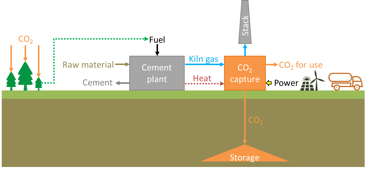
Table 1.
Summary of carbon capture technologies evaluated and planned in the cement sector
| Technology | Project | Test Location | Operation | Scale of Field Test | Type | Energy Consumption | Cost |
|---|---|---|---|---|---|---|---|
| SkyMine® | SkyMine® Beneficial CO2 Use Project | Capitol Aggregates’ San Antonio cement plant, Texas, United States of America | 2015– | 76,488 t CO2/y | CCU | 8.3 GJe/t CO2 [23] | $125 M a [23] |
| Aker Solution’s ACCTM | Norcem CO2 capture project | Norcem’s cement plant, Brevik, Norway | 2014–2015 | 450 Nm3/h kiln flue gas 140–250 kg CO2/h | capture | 3.0 GJ/t CO2 b,c,d 2.7 GJ/t CO2 b,d 0 GJ/t CO2 b [36] | NA |
| Aker Solution’s ACCTM | Norway’s full chain CCS | Norcem’s cement plant, Brevik, Norway | 2023– | 400,000 t CO2/y | CCS | NA | NA |
| Amine scrubbing | Anhui Conch Cement project | Anhui Conch’s cement plant in Wuhu, China | 2018– | 50,000 t CO2/y | CCU | NA | $10 M |
| CDRMax® | Dalmia Cement project | Dalmia cement’s plant in Tamil Nadu, India | NA | 500,000 t CO2/y | CCU | NA | $40/t CO2 [44] |
| CAP | CEMCAP | GE’s Technology Center in Växjö, Sweden | 2015–2018 | - | Individual components tested: absorber, DCC-scrubber and water wash | 2.37 GJ/t CO2 b [47] 3.75 GJ/t CO2 e [46] | 66.2 €/t CO2 [37] |
| Membranes | Norcem CO2 capture project | Norcem’s cement plant, Brevik, Norway | 2014 | NA | capture | NA | NA |
| Membranes | MemCCC project | Norcem’s cement plant, Brevik, Norway | 2016 | 37 Nm3/h kiln flue gas | capture | 1.20 GJe/t CO2 [51] | 47–48 €/t CO2 d [51] |
| MAL | CEMCAP | TNO, Eindhoven, Netherlands and SINTEF Energy Research, Trondheim, Norway | 2015–2018 | - | Individual components tested separately: membranes and liquefaction | 3.22 GJe/t CO2 e [46] | 83.5 €/t CO2 [37] |
| RTI solid sorbent technology | Norcem CO2 capture project | Norcem’s cement plant, Brevik, Norway | 2016 | NA | capture | 2.4 GJ/t CO2 b,c,d [56] | 45.8 €/t CO2 c,d 40.7 €/t CO2 d 38.6 €/t CO2 [56] |
| VeloxothermTM | LafargeHolcim Cement Carbon Capture | Holcim Portland cement plant, Colorado, United States of America | 2023– | 2,000,000 t CO2/y | CCUS (EOR) | NA | $150 M $50/t CO2 [60] |
| VeloxothermTM | CO2MENT | Lafarge’s Richmond British Columbia cement plant, Canada | 2019–2022 | 1 t CO2/d | CCU | NA | $28 M |
| HECLOT | ITRI’s Calcium Looping Pilot | Ho Ping Cement plant, Taiwan | 2013– | 1 t CO2/h | capture | NA | $30/t CO2 [67] |
| RCC | Norcem CO2 capture project | Institute of Combustion and Power Plant Technology at the University of Stuttgart (IFK), Germany | 2013–2017 | - | - | 3.13 GJ/t CO2 e,h 1.45 GJ/t CO2 e,i [71] | NA |
| CaL | CEMCAP | IFK, Stuttgart University, Germany INCAR-CSIC, Spain | 2015–2018 | - | - | 4.42 GJ/t CO2 e,f,h 4.07 GJ/t CO2 e,g,h 3.17 GJ/t CO2 e,i [65] | 52.4 €/t CO2 h 58.6 €/t CO2 i [37] |
| Entrained CaL | CLEANKER | Buzzi Unicem Vernasca cement plant, Italy | 2019–2021 | 1000 Nm3/h kiln flue gas | capture and mineralization testing | NA | NA |
| Oxyfuel combustion | CEMCAP | HeidelbergCement plant, Hannover | 2015–2018 | - | oxyfuel prototype testing: clinker cooler and burner | 1.63 GJ/t CO2 e | 42.4 €/t CO2 [37] |
| Oxyfuel combustion | ECRA’s CCS project | HeidelbergCement plant in Coleferro, Italy Lafarge Holcim plant in Retznei, Austria | NA | NA | NA | NA | 80 M€ [80] |
| Direct capture | LEILAC | Lixhe, Belgium | 2020 | 25,000 t CO2/y | NA | NA | NA |
| Direct capture | LEILAC 2 | Heidelberg cement plant in Western Europe | 2020–2024 | 100,000 t CO2/y | NA | NA | NA |
a Installed costs; b Specific reboiler duty (SRD); c Without heat recovery; d 85% capture rate; e Specific primary energy consumption per CO2 avoided (SPECCA); f 20% integration; g 50% integration; h tail-end; i integrated; NA: Not available.
Publisher’s Note: MDPI stays neutral with regard to jurisdictional claims in published maps and institutional affiliations. |
© 2020 by the authors. Licensee MDPI, Basel, Switzerland. This article is an open access article distributed under the terms and conditions of the Creative Commons Attribution (CC BY) license (http://creativecommons.org/licenses/by/4.0/).
Share and Cite
MDPI and ACS Style
Plaza, M.G.; Martínez, S.; Rubiera, F. CO2 Capture, Use, and Storage in the Cement Industry: State of the Art and Expectations. Energies 2020, 13, 5692. https://doi.org/10.3390/en13215692
AMA Style
Plaza MG, Martínez S, Rubiera F. CO2 Capture, Use, and Storage in the Cement Industry: State of the Art and Expectations. Energies. 2020; 13(21):5692. https://doi.org/10.3390/en13215692
Chicago/Turabian StylePlaza, Marta G., Sergio Martínez, and Fernando Rubiera. 2020. "CO2 Capture, Use, and Storage in the Cement Industry: State of the Art and Expectations" Energies 13, no. 21: 5692. https://doi.org/10.3390/en13215692
Note that from the first issue of 2016, this journal uses article numbers instead of page numbers. See further details here.