Impact of Selected Methods of Cogging Torque Reduction in Multipolar Permanent-Magnet Machines
by
 , ,
, ,
Zbigniew Goryca
1, 
Sebastian Różowicz
2,*,
Antoni Różowicz
2,
Artur Pakosz
3,
Marcin Leśko
4 and
Henryk Wachta
4 1
Faculty of Environmental, Geomatic and Energy Engineering at the Kielce University of Technology, al. Tysiąclecia Państwa Polskiego 7, 25-314 Kielce, Poland
2
Department of Industrial Electrical Engineering and Automatic Control, Kielce University of Technology, 7 Tysiąclecia Państwa Polskiego Str., 25-314 Kielce, Poland
3
Research and Development Department, the Central Military Bureau of Design and Technology, 03-244 Warszawa, Poland
4
Department of Power Electronics and Power Engineering, Rzeszow University of Technology, Wincentego Pola 2, 35-959 Rzeszow, Poland
*
Author to whom correspondence should be addressed.
Energies 2020, 13(22), 6108; https://doi.org/10.3390/en13226108
Submission received: 4 November 2020
/
Revised: 18 November 2020
/
Accepted: 19 November 2020
/
Published: 21 November 2020
(This article belongs to the Special Issue Design and Analysis of Electric Machines)
Abstract
:This paper focuses on the matter of cogging torque reduction by combining various methods of cogging torque minimization. Due to the high costs of prototype construction, cogging torque is minimized during the design phase by using numerical methods, while computer simulations are used to find a magnetic circuit arrangement for which the cogging torque has the smallest possible value. Cogging torque occurs as a result of combined impact of the magnetic field of a permanent magnet located at rotor and stator with variable magnetic conductivity depending on an angle of rotation. It is a pulsating torque and occurs permanently during machine operation, impacting the operation of the entire device cooperating with the electric machine and causing vibrations, tension, and noise. It results in braking torque and subsequent power losses and leads to faster wear and tear of machine structural elements. High cogging torque values cause problems with rotational speed adjustment. In the case of electric generators used in wind power plants, it impedes the start-up of power plants at high wind speeds. Considering the above, the reduction of cogging torque in permanent-magnet machines is extremely important.
1. Introduction
Innovative electric machines are characterized by such parameters as high efficiency, high energy density, high reliability and compact size. All these parameters can be achieved thanks to simultaneously occurring progress in the area of machine design and to rapid development in related areas of science, namely power electronics, materials engineering, and microprocessor techniques [1,2]. Reaching high efficiency in electric machines is possible thanks to the application of advanced computer techniques during the design process [3,4,5]. These techniques are used to calculate electromagnetic field arrangement and to optimize machine structure. The development of power electronics enables semiconductors to control machines with gradually increasing power capacities, while the microprocessor technique ensures the realization of the control process. of the use of rare-earth elements (NdFeB, SmCo) in magnets allows for the production of electric machines with energy density 10 times higher than by using traditional ferrite magnets and AlNiCo [1]. Combining these elements results in the production of innovative energy-saving motors, widely used in industry, and permanent-magnet electric generators used in renewable energy generation systems [6]. Permanent-magnet electric machines have multiple pros and two cons: they are more expensive than asynchronous machines, and are characterized by cogging torque that occurs as a result of the combined impact of the magnetic field of permanent magnets and a stator with variable magnetic conductivity. It is a pulsating torque and occurs permanently during machine operation [7], impacting the operation of the entire device cooperating with the electric machine and causes vibrations, noise, braking torque, power losses and problems with rotational speed adjustment [8]. As a result of these adverse phenomena, minimization of the cogging torque is still an unsolved problem in permanent-magnet machines, and finding the most efficient minimization methods is of high importance [9,10,11,12,13,14,15].
2. Cogging Torque
Permanent-magnet motor torque is the sum of three components depending on rotor position: torsional excitation value, reluctance torque, and cogging torque.
where: Te is the torque, Tw is the torsional excitation value, Tr is the reluctance torque, Tz is the cogging torque, and αm is the angle between rotor and stator.
Torsional excitation occurs as a result of the combined impact of the stator field and the rotor magnetic field and constitutes the driving element of the rotor. The reluctance torque occurs as a result of a change in rotor reluctance for the stator field. In permanent-magnet motors with magnet permeability being close to vacuum permeability, the reluctance torque is negligibly low. The cogging torque occurs as a result of the combined impact of the magnetic field created by permanent magnets and the stator with angular variation of magnetic conductivity. The cogging torque is determined with electric power disconnected, and is undesirable because it constitutes the braking torque, impedes start-up of a machine, and increases vibrations and noise levels, leading to faster wear and tear of motor components. Periods of oscillation for certain components depend on the numbers of Q grooves and p pole pairs (Table 1):
The static electromagnetic torque in a brushless motor is a periodic function of the rotor tilt angle. As a result of the complete elimination of the reluctance and cogging torques, the electromagnetic torque will depend only on torsional excitation. In this paper, we focus on cogging torque reduction.
In a permanent-magnet electric motor, the electromagnetic torque is produced by the combined impact of the current flowing through the coil and the magnetic field of permanent-magnet excitation. The value of the torque being created can be calculated as changed motor magnetic co-energy for changed rotor angular position. This relation is expressed by the following equation:
where Te is the electromagnetic torque, Ec is the magnetic co-energy, and α is the angular position.
If no voltage drops in the ferromagnetic part of the magnetic circuit and linear demagnetization of a magnet are assumed, the magnetic co-energy and magnetic energy are equal. In this case, calculations can be limited to the magnetic field parameters in an air gap:
where Ec is the magnetic co-energy, Bδ is induction in the air gap, Hδ is the air gap electric field, V is the air gap volume, and µ0 is vacuum permeability.
Static field magnetic co-energy is a function of the position of a rotor and strand currents. For linear demagnetization magnets, magnetic co-energy can be treated as the sum of components, depending only on the position, and the component depending on position and current :
where Ec is the magnetic co-energy, α is the angular position, ik is the instantaneous current in a given strand, and k = 1,…n is the coil strand number.
With electric power disconnected, co-energy takes the form depending only on rotor position:
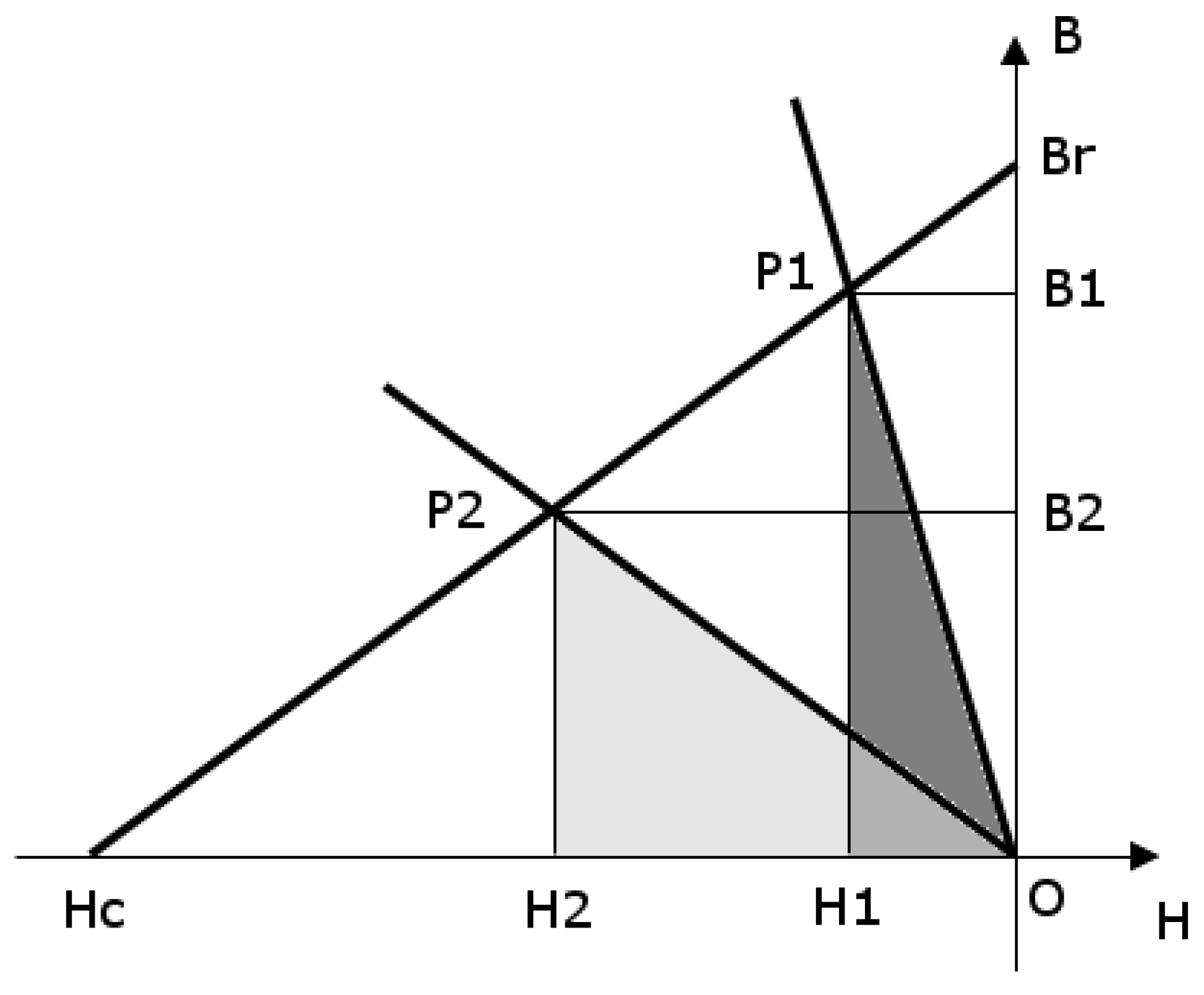
When the rotor rotates in relation to the stator, changes in magnetic co-energy occur, resulting from variable permeance of the excitation flux. In a linear magnetic circuit, decreased permeance results in displacement of the operating point from P1 to P2 of the demagnetization characteristics (Figure 1). Operating point displacement results in a change of magnetic co-energy defined by the area of the P1H1O triangle to the area of the P2H2O triangle [16].
where Hc is the coercive voltage and Br is remanence induction.
Gap magnetic flux can be expressed as follows:
where ϕ is the magnetic flux in the air gap, B is the air magnetic induction, and S is the gap area (the surface of the cylinder inside the air gap).
Magnetic flow can be expressed as follows:
where θ is magnetic flow, H is magnetic field strength, and l is gap length.
Internal energy can be expressed by means of an integral of magnetic flow in relation to flux:
where ϕ is the magnetic flux in the air gap, θ is magnetic flow, E is internal energy, Λµ(α) is permeance for flux from magnets, and α is the rotor position in relation to the stator.
After substituting the relation from Equation (8) to Equation (3), the cogging torque can be determined as:
where Tz is the cogging torque, Ec is the magnetic co-energy, ϕ is the magnetic flux in the air gap, Λµ(α) is permeance for flux from magnets, and α is the rotor position in relation to the stator.
We can see in the Equation (9) that cogging torque occurs as a result of variable magnetic circuit permeance for permanent magnet flux. Magnetic circuit permeance is a sum (Equation (10)) of the constant component (Equation (11)) and the variable component (Equation (12)) depending on rotor position. In order to simplify our deliberations the permeance variable component consists only of a basic harmonic:
where Λ is the magnetic circuit permeance, Λs is the permeance constant component, Λz is the permeance variable component, Λmax is the maximum permeance value, Λmin is the minimum permeance value, Q is the number of grooves, p is the number of pole pairs, NWW is the least common multiple, and α is the rotor position in relation to the stator.
Thus, the period of oscillation for the permeance variation component is determined by the value of the least common multiple of the numbers of grooves and pole pairs:
where TΛ is the permeance period of oscillation, p is the number of pole pairs, Q is the number of grooves, and NWW is the least common multiple.
Considering Equations (9) and (13), cogging torque permeance depends on the least common multiple of the numbers of grooves and pole pairs.
The amplitude of the permeance variable component depends on the machine’s material and structural parameters. In order to minimize the cogging torque and maximize the electromagnetic torque, permeance should have the highest possible value of the constant component and no variable component. The most common method used to minimize the permeance variable component and the cogging torque is groove beveling [17]. Due to the high costs of prototype construction, the cogging torque is minimized during the design phase by using numerical methods, while computer simulations are used to find a magnetic circuit arrangement for which the cogging torque has the smallest possible value
3. Simulation Tests
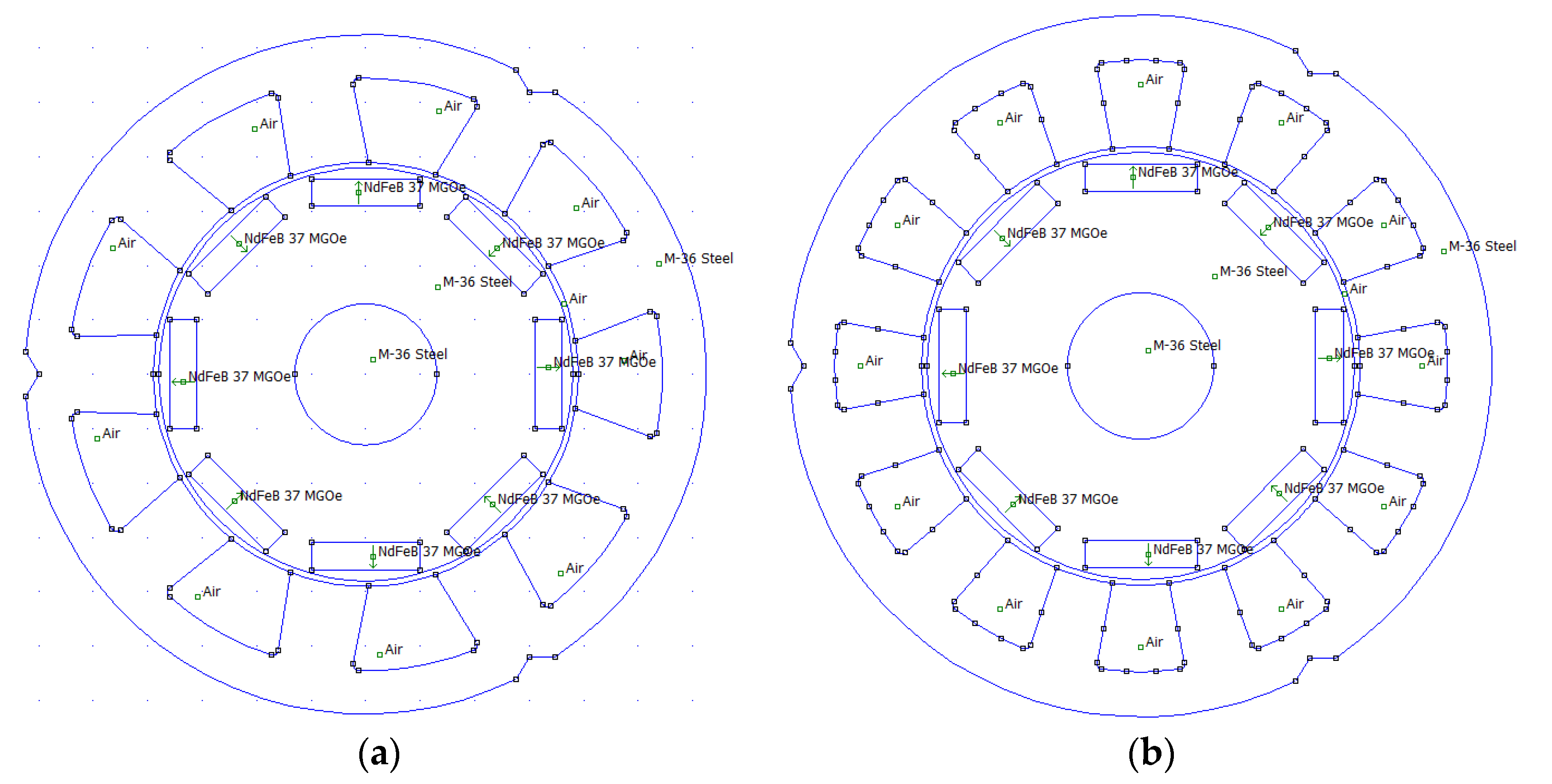
Two DCPM motors were selected for tests. The magnetic circuits of the motors are presented in Figure 2.
The output parameters of the motors are presented in Table 2.
The numbers of stator teeth in the motors differ: there are 9 in the asymmetric motor and 12 in the symmetric motor. There are eight rotor magnets in each of the machines.
The simulation models [18,19,20,21] were developed from the software FEMM 4.1 library. We selected materials used for simulation and defined the areas containing coils. Certain model areas were assigned to the selected materials, and coils were assigned to current values. It was initially assumed that the magnetic field would not go beyond the machine, so the zero boundary conditions were defined for the stator. A series of trial calculations were performed in order to select a size of the calculation grid enabling us to obtain uniform, linear-like torque characteristics for a satisfactory calculation period length. If a 2D software is used, the number of reduction methods that can be used for tests is limited.
Among the known cogging torque reduction methods [3,22], the following were selected for tests: asymmetric arrangement of rotor magnets and decreasing of groove orifice width.
It was decided to test all possible combinations in the parameter variability range being selected.
4. Testing of the Asymmetric Machine
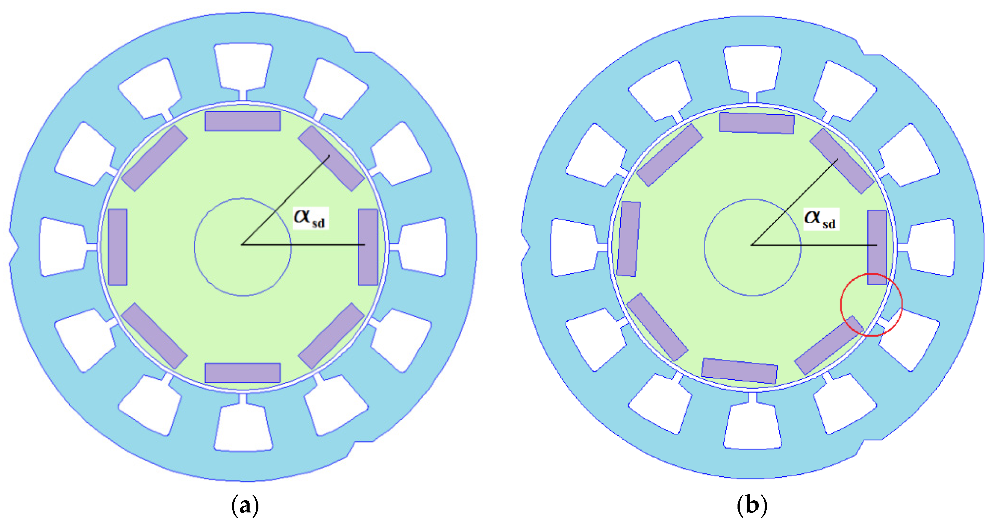
The stator of the asymmetric DCPM motor has nine teeth and there are eight diagonally magnetized NdFEB37 neodymium magnets in the rotor. In order to provide symmetric arrangement of magnets in the rotor, the angle between them is 45 degrees. Asymmetric arrangement occurs by displacing magnets in relation to a previous one by a fixed angle. For simulation purposes, the angle change to be applied between adjacent magnets was determined to be between 44 and 45 degrees with a pitch of 0.1 degree.
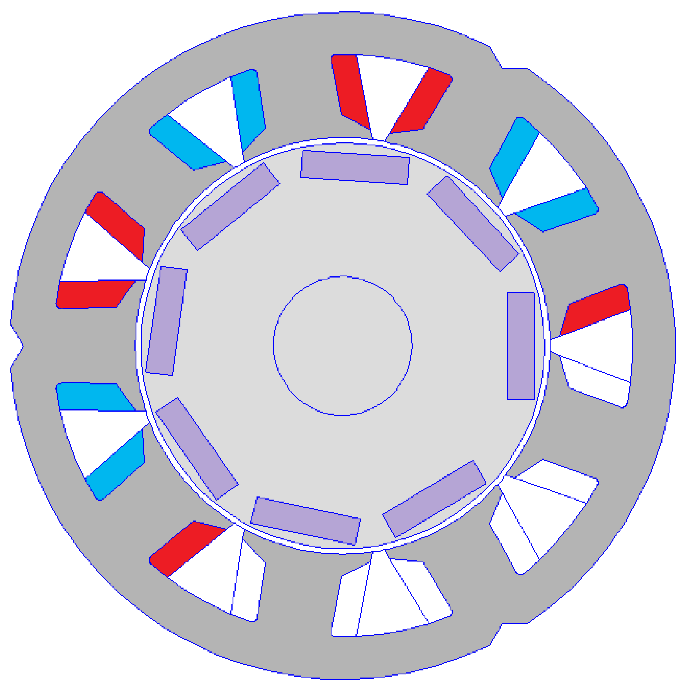
Figure 3 presents an example of the asymmetric stator with the symmetric rotor, for which the αsd angle is 45 degrees, and with the asymmetric rotor, for which the αsd angle is 44 degrees.
Groove orifice width was adjusted from 12.58 mm, being equal to stator tooth width, to 2.25 mm with a pitch of circa 1 mm. The calculation automation script generated the grid, calculated cogging and useful torque values, displaced the rotor to the next position, and repeated the calculations. Results were saved in text files for subsequent editing and importing to a spreadsheet. For motor useful torque calculation, a default grid turned out to be sufficient. The cogging torque required thickening of the grid in the gap to the size of 0.1 mm.
For the purposes of useful torque calculation, additional coils were mounted around the stator’s teeth and the number of coils in each inductor and current flowing through an inductor were determined, as shown in Figure 4. The i+ currents are marked in red and the i- currents are marked in blue.
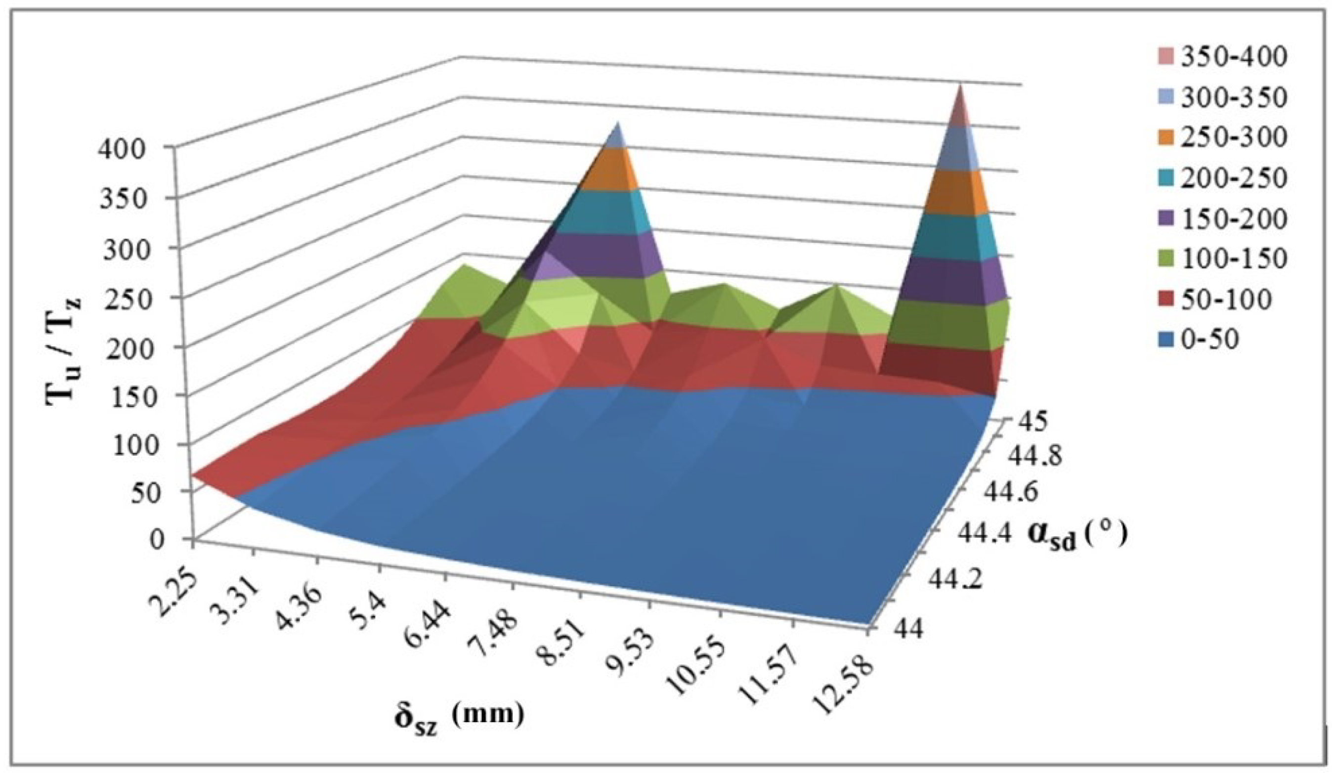
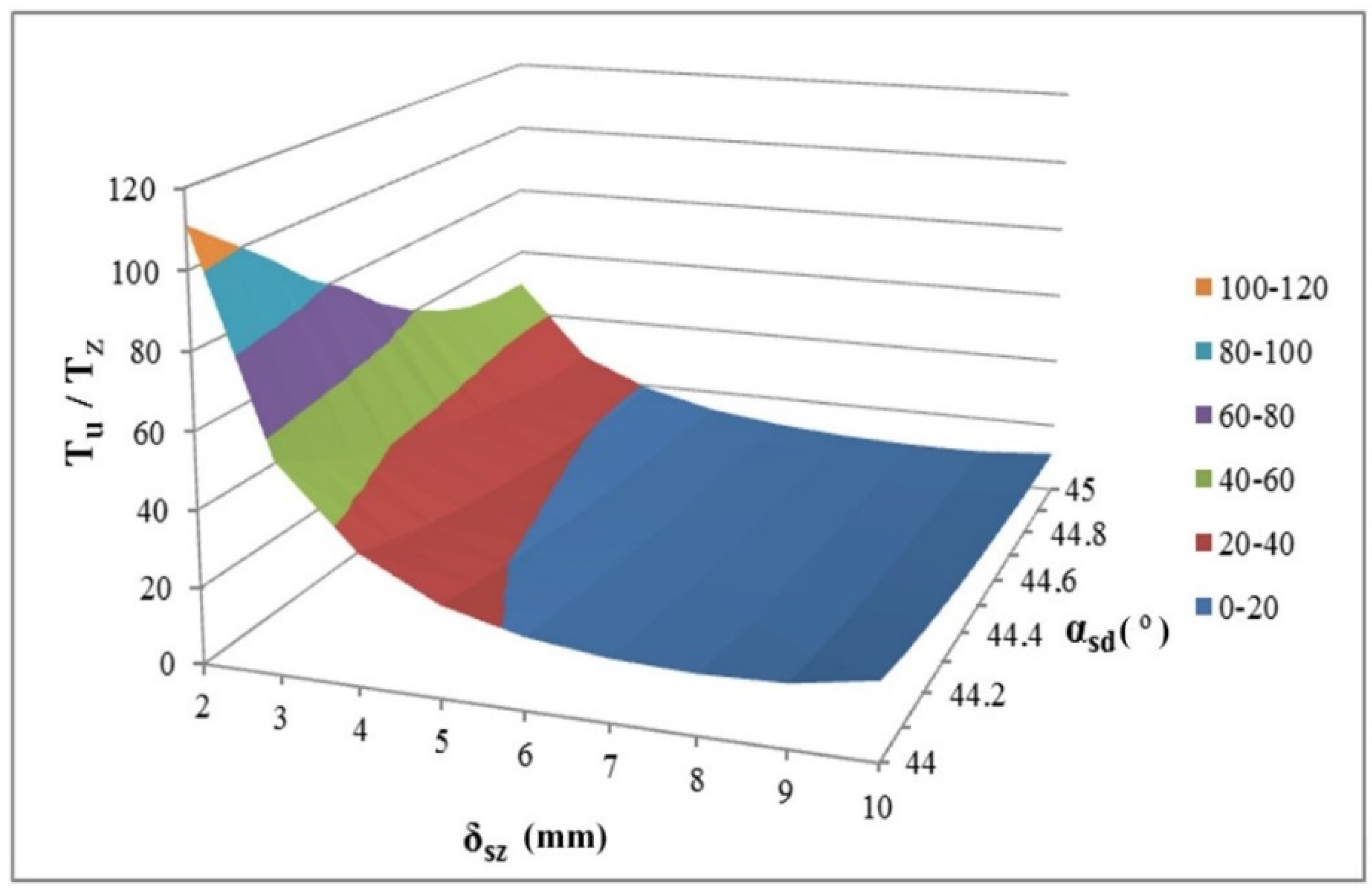
Apart from minimizing the cogging torque itself, cogging torque reduction methods also change the useful torque. With the intention of finding a model with the highest possible Tu/Tz coefficient, it was decided to determine the ratio between the useful torque and the cogging torque for all simulations. The results are presented in Table 3 and in Figure 5.
In Table 3 in the green-marked area (δsz 3.31–12.58, αsd 44–44.5), where stator and rotor are asymmetric parts, there is a clearly visible minimum in the 3D graph, while a change of any parameters, displacement angle of adjacent αsd magnets, or δsz groove orifice width cause displacement towards areas with higher efficiency. Better parameters can be achieved for the model with a symmetric rotor than for the model with an asymmetric one. This part of the graph is irregular and has several local maxima.
5. Testing of the Symmetric Machine
The stator of the symmetric DCPM motor has 12 teeth, and there are 8 diagonally magnetized NdFEB37 neodymium magnets in the rotor. In order to provide a symmetric arrangement of magnets in the rotor, the angle between them is 45 degrees. Asymmetric arrangement occurs by displacing magnets in relation to a previous one by a fixed angle. For simulation purposes the angle change to be applied between adjacent magnets was determined to be between 44 and 45 degrees with a pitch of 0.1 degree. Figure 6 presents an example of the symmetric stator with the symmetric rotor, for which the αsd angle is 45 degrees, and with the asymmetric rotor, for which the αsd angle is 44 degrees. Groove orifice width was adjusted from 10 mm to 2 mm with a pitch of circa 1 mm.
As in the previous model, the LUA language script was written to generate the calculation grid, calculate the useful torque and the cogging torque by means of the Maxwell stress tensor method [23,24], and displace the rotor to the next location, as specified in the programmed pitch. Calculation results were saved in text files. In this case it was sufficient to use a default grid to calculate the motor useful torque. The cogging torque required thickening of the grid in the gap to the size of 0.1 mm.
For the purposes of useful torque calculation in the basic model of the DCPM motor being tested, additional coils were mounted around the stator’s teeth, and the number of coils in each inductor and the current flowing through an inductor were determined, as shown in Figure 7. The i+ currents are marked in red and the i− currents are marked in blue.
Apart from reduction of the cogging torque itself, cogging torque minimization methods can also change the useful torque. Considering the above, it is necessary to look for a model with the best possible ratio between the useful torque and the cogging torque. It was decided to determine the Tu/Tz coefficient for all configurations being tested. Results are presented in Table 4.
For better illustration of the results from Table 4 we decided to construct a 3D graph for the Tu/Tz coefficient depending on the displacement angle for the adjacent magnets αsd and δsz groove orifice width. The graph for all measurements is presented in Figure 8.
Decreasing the gap and the angle between the adjacent magnets results in increasing values of the Tu/Tz coefficient. In this case, the single best solution is determined for the entire range being assessed, regardless of which cogging torque reduction method is selected first.
Figure 9 shows the Tu/Tz coefficient at the single graph for both the symmetric model (on the left) and the asymmetric model (on the right). The figure proves that the asymmetric motor is the better solution in terms of energy-related values.
6. Experimental Determination of the Cogging Torque
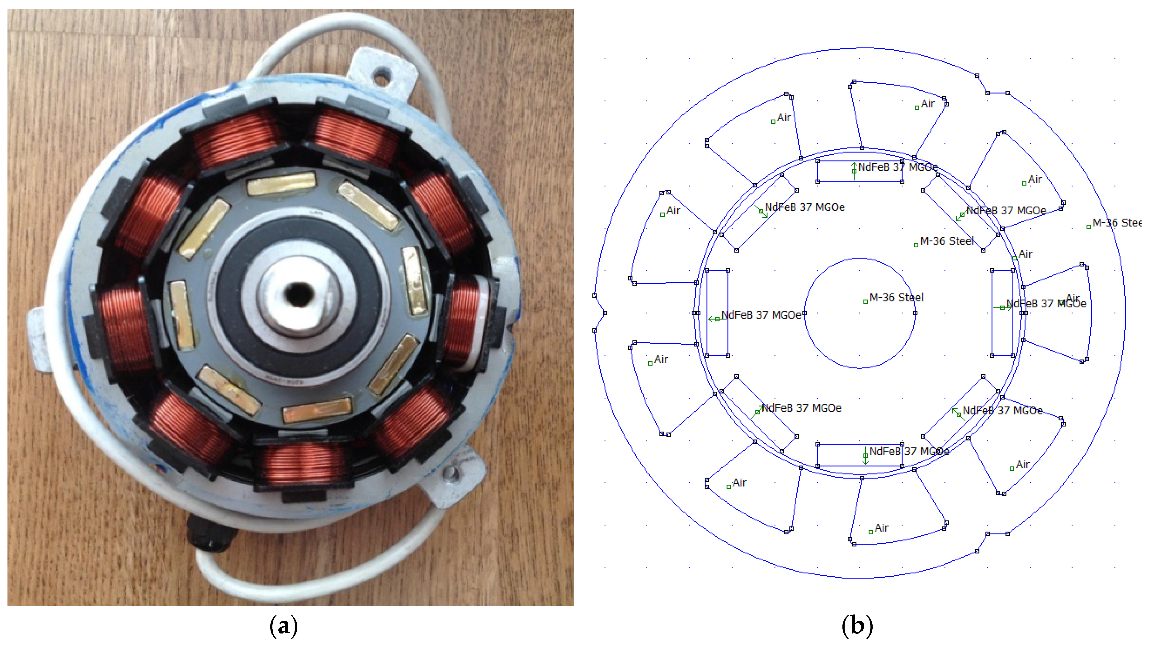
In order to verify calculation results the prototype motor was constructed (Figure 10) and cogging torque measurements were performed [25].
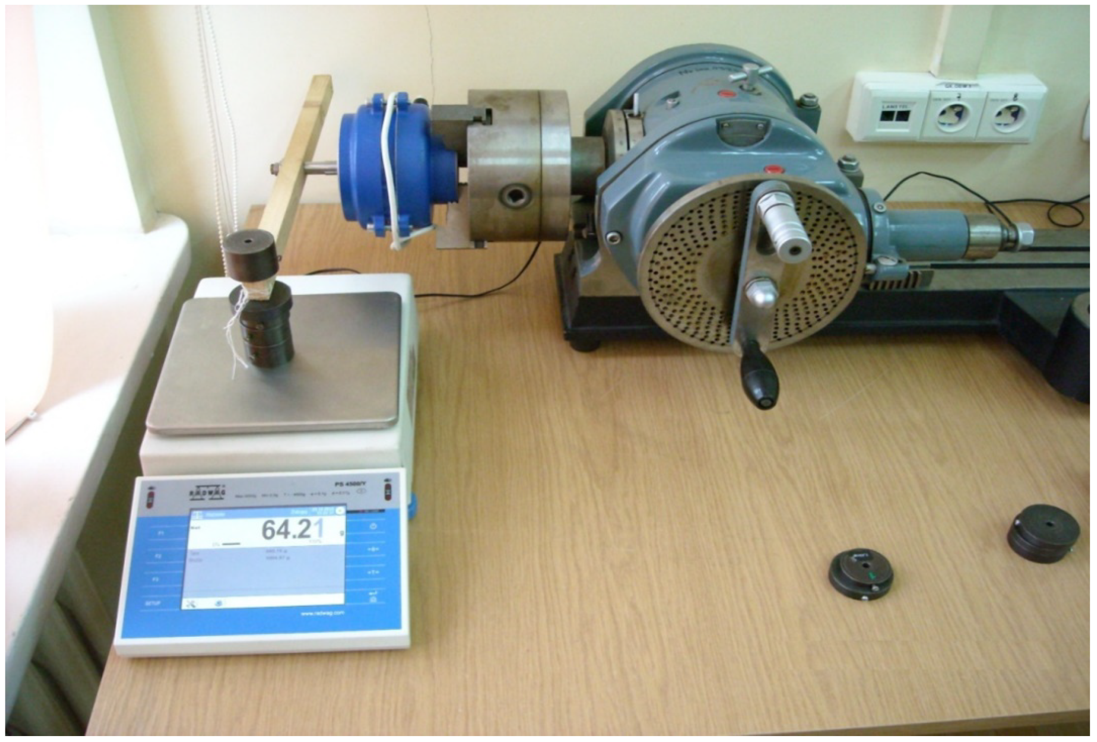
The static cogging torque calculation method specified below is performed as follows: the machine rotor is permanently connected to the balanced lever in the form of a single-side-weighted flat bar. The end of the lever with the weight is placed on a digital scale. The machine rotor is connected to the indexing head (Figure 11). Change of indexing head revolution angle results in changed stator position in relation to the rotor, thus leading to changed pressure of the level on the scale.
The cogging torque is calculated as defined by Equation (14) on the basis of scale read-outs and knowledge of the lever arm.
where Tz is the torque being tested, mn is the scale read-out, g is standard gravity, and rd is the lever radius.
In order to compare the results of the laboratory measurements and the simulation calculations, the joint graph for both cases was developed (Figure 12). On both graphs, measurement and calculation errors were detected. The measurement and simulation results are convergent, and thus cogging torque computations should be deemed correct. The lab index refers to lab measurements, while the Femm index refers to calculation results obtained by means of the finite element method.
7. Conclusions
On the basis of the performed tests, the following conclusions were drawn. 2D calculations give results that are very similar to the real ones. Modification of the machine’s magnetic circuit may result in the occurrence of additional harmonics in the cogging torque, and this is particularly detectable during transformation from the symmetric structure to the asymmetric structure. The accuracy of cogging torque calculations depends mostly on the gap grid density (the higher, the better). In other parts of the magnetic circuit, the grid can have default values. As the cogging torque is not the only criterion assessed during the design of electric machine magnetic circuits, the design of machines with optimum parameters should be performed using genetic algorithms considering multiple parameters and their reciprocal impact. Due to magnetic circuit structure, not all cogging torque reduction methods appropriate for application in a given motor will be suitable for use in another. The use of just one method causes significant reduction of the cogging torque. The best cogging torque minimization results are obtained for the following configurations: symmetric stator with asymmetric rotor or asymmetric stator and symmetric rotor. Other configurations produce worse results. Application of another method for the model with an already-reduced smallest value of the cogging torque results in its additional reduction, though not to the same extent as the primary method. In the case of the application of two cogging torque reduction methods in a different order, we can obtain the machine with the smallest cogging torque value.
Author Contributions
Conceptualization: Z.G., A.R., and M.L.; Formal analysis: S.R.; Investigation: H.W.; Methodology: S.R., Z.G., A.R., and A.P.; Resources: H.W.; Writing—original draft: S.R., Z.G., and M.L.; Writing—review and editing: A.P. and H.W. All authors have read and agreed to the published version of the manuscript.
Funding
This research received no external funding.
Conflicts of Interest
The authors declare no conflict of interest.
References
- Goryca, Z.; Korkosz, M.; Mazur, D.; Rossa, R.; Ziółek, M. Przydatność wybranych programów polowych do obliczania momentu zaczepowego wielobiegunowej maszyny z magnesami trwałymi. Zesz. Probl. Masz. Elektr. 2014, 3, 179–183. [Google Scholar]
- Gajewski, M. Analiza Pulsacji Momentu w Silnikach Bezszczotkowych z Magnesami Trwałymi; Rozprawa doktorska; Politechnika Warszawska: Warszawa, Poland, 2007. [Google Scholar]
- Hwang, S.M.; Eom, J.B.; Hwang, G.B.; Jeong, W.B.; Jung, Y.H. Cogging torque and acoustic noise reduction in permanent magnet motors by teeth pairing. IEEE Trans. Magn. 2000, 36, 3144–3146. [Google Scholar] [CrossRef]
- Sitapati, K.; Germain, R.S. Reducing Cogging Torque in Brushless Motors. Available online: http://machinedesign.com/motorsdrives/reducing-cogging-torque-brushless-motors (accessed on 10 November 2020).
- Steinbrink, J. Analytical determination of the cogging torque in brushless motor excited by permanent magnets. In Proceedings of the IEEE International Electric Machines & Drives Conference, Antalya, Turkey, 3–5 May 2007; pp. 172–177. [Google Scholar]
- Młot, A. Konstrukcyjne metody ograniczania pulsacji momentu elektromagnetycznego w bezszczotkowym silniku prądu stałego z magnesami trwałym. Autoref. Rozpr. Dr. 2007, 322, 27–28. [Google Scholar]
- Ziółek, M. Rozprawa Doktorska, Analiza Pracy Silnika Bezszczotkowego z Cylindrycznym Uzwojeniem i Zewnętrznym Wirnikiem; Politechnika Warszawska Wydział Elektryczny: Warszawa, Poland, 2013. [Google Scholar]
- Zhu, L.; Jiang, S.Z.; Zhu, Z.Q.; Chan, C.C. Analytical methods for minimizing cogging torque in permanent-magnet machines. IEEE Trans. Magn. 2019, 45, 2023–2031. [Google Scholar] [CrossRef]
- Henrotte, F.; Hameyer, K. Computation of electromagnetic force densities: Maxwell stress tensor vs. virtual work principle. J. Comput. Appl. Math. 2004, 168, 235–243. [Google Scholar] [CrossRef] [Green Version]
- Ishak, D.; Zhu, Z.Q.; Howe, D. High torque density permanent magnet brushless machines with similar slot and pole numbers. J. Magn. Magn. Mater. 2004, 272–276, 1767–1769. [Google Scholar] [CrossRef]
- Zieliński, P.; Schoepp, K. Wolnoobrotowe generatory synchroniczne wzbudzane magnesami trwałymi o uzwojeniach skupionych. In Prace Naukowe Instytutu Maszyn, Napędów i Pomiarów Elektrycznych Politechniki Wrocławskiej, Studia i Materiały; Oficyna Wydawnicza Politechniki Wrocławskiej: Wrocław, Poland, 2006. [Google Scholar]
- Glinka, T. Maszyny Elektryczne Wzbudzane Magnesami Trwałymi; Wydawnictwo Politechniki Śląskiej: Gliwice, Poland, 2002. [Google Scholar]
- Jonczyk, J.; Kołodziej, J. Modelowanie Zagadnień Polowych z Wykorzystaniem MES; Praca magisterska; Politechnika Opolska: Opole, Poland, 2004. [Google Scholar]
- Zhu, Z.Q.; Howe, D. Influence of design parameters on cogging torque in permanent magnet machines. IEEE Trans. Energy Convers. 2000, 15, 407–412. [Google Scholar] [CrossRef] [Green Version]
- Yang, Y.; Wang, X.; Zhang, R.; Zhu, C.; Ding, T. Research of cogging torque reduction by different slot width pairing permanent magnet motors. In Proceedings of the 8th International Electric Machines and Systems Conference, Nanjing, China, 27–29 September 2005; pp. 367–370. [Google Scholar]
- Zhu, Z.Q.; Chen, J.T.; Wu, L.J.; Howe, D. Influence of stator asymmetry on cogging torque in permanent magnet machines. IEEE Trans. Magn. 2008, 44, 3851–3854. [Google Scholar] [CrossRef]
- Goryca, Z. Wpływ doboru liczby biegunów magnetycznych na moment zaczepowy maszyny z magnesami trwałymi. In Proceedings of the Konferencja Modelowanie, Symulacja i Zastosowania w Technice, Kościelisko, Poland, 18–22 June 2012. [Google Scholar]
- Krykowski, K.; Silnik, P.M. BLDC w Napędzie Elektrycznym Analiza, Właściwości, Modelowanie; Wydawnictwo Politechniki Śląskiej: Gliwice, Poland, 2011. [Google Scholar]
- Goryca, Z.; Paduszyński, K.; Pakosz, A. Model of the multipolar motor with decreased cogging torque by asymmetrical distribution of the magnets. Open Phys. 2018, 16, 42–45. [Google Scholar] [CrossRef] [Green Version]
- Koh, C.S.; Seol, J.S. New cogging torque reduction method for brushless permanent-magnet motors. IEEE Trans. Magn. 2003, 39, 3503–3506. [Google Scholar]
- Libert, F.; Soulard, J. Investigation on pole-slot combinations for permanent magnet machines with concentrated windings. In Proceedings of the International Conference on Electrical Machines and Systems (ICEMS), Hangzhou, China, 22–25 October 2014. [Google Scholar]
- Łukaniszyn, M.; Młot, A. Analiza momentu elektromagnetycznego i składowych pulsacji w bezszczotkowym silniku prądu stałego wzbudzanym magnesami trwałymi. Przegląd Elektrotechniczny 2005, 10, 21–25. [Google Scholar]
- Goryca, Z.; Ziółek, M. Modelowanie pola magnetycznego silnika wentylatora. In Proceedings of the IV Ogólnopolska Konferencja Modelowanie i Symulacja MiS-4, Kościelisko, Poland, 19–23 June 2006. [Google Scholar]
- Gawęcki, Z. Wpływ skosu żłobków stojana na moment zaczepowy silnika bezszczotkowego. In Proceedings of the XIII International PhD Workshop OWD, Wisła, Poland, 22–25 October 2011. [Google Scholar]
- Mazur, D. Analiza momentu zaczepowego oraz indukcji magnetycznej w szczelinie dla prądnicy synchronicznej metodą MES. Pomiary Autom. Kontrola 2012, 58, 1019–1021. [Google Scholar]
Figure 1.
Change of the operating point for a linear circuit.

Figure 2.
Basic simulation models of DCPM motors: asymmetric motor on the (a) and symmetric motor on (b).
Figure 2.
Basic simulation models of DCPM motors: asymmetric motor on the (a) and symmetric motor on (b).

Figure 3.
Example of the asymmetric machine with the symmetric rotor (a) and the asymmetric rotor (b).
Figure 3.
Example of the asymmetric machine with the symmetric rotor (a) and the asymmetric rotor (b).

Figure 4.
DCPM motor and stator’s segment with coils added.

Figure 5.
3D graph for the Tu/Tz coefficient for the asymmetric DCPM motor.

Figure 6.
Example of the symmetric (a) and asymmetric (b) machines.

Figure 7.
DCPM motor and stator segment with coils added.

Figure 8.
3D graph for the Tu/Tz coefficient for the asymmetric DCPM motor.

Figure 9.
Tu/T coefficient for the symmetric model (on the left) and the asymmetric model (on the right).
Figure 9.
Tu/T coefficient for the symmetric model (on the left) and the asymmetric model (on the right).

Figure 10.
Real model (a) and simulation model (b) of the motor being tested.

Figure 11.
Cogging torque measurement stand.

Figure 12.
Comparison of cogging torques in the laboratory DCPM motor and the simulation DCPM motor.
Figure 12.
Comparison of cogging torques in the laboratory DCPM motor and the simulation DCPM motor.


Table 1.
Periods of oscillation for certain components.
| Torque | Period of Oscillation |
|---|---|
| Torsional excitation | |
| Reluctance torque | |
| Cogging torque | |
| Electromagnetic torque |
Table 2.
List of parameters of the DCPM motors being tested.
| Parameter | Value |
|---|---|
| power | 150 W |
| velocity | 500 rpm |
| torque | 3 Nm |
| voltage | 24 V |
| current | 6.25 A |
| number of inductors | 9 |
| number of coils | 70 |
| wire diameter | 0.8 mm |
| outer stator diameter | 125 mm |
| inner stator diameter | 78 mm |
| air gap | 1 mm |
| rotor diameter | 76 mm |
| sheet metal plate package width | 20 mm |
| magnets (magnetized diagonally) | 20 × 5 × 20 mm |
| pole pitch filling coefficient | 75% |
Table 3.
List of ratios between useful torque and cogging torque in the DCPM motor being tested for full rotor revolution.
Table 3.
List of ratios between useful torque and cogging torque in the DCPM motor being tested for full rotor revolution.
| αsd (o) | 44 | 44.1 | 44.2 | 44.3 | 44.4 | 44.5 | 44.6 | 44.7 | 44.8 | 44.9 | 45 | |
|---|---|---|---|---|---|---|---|---|---|---|---|---|
| δsz (mm) | ||||||||||||
| 2.25 | 68.48 | 70.16 | 70.93 | 66.86 | 65.28 | 65.81 | 71.31 | 82.62 | 102.20 | 125.36 | 137.34 | |
| 3.31 | 41.47 | 45.60 | 50.10 | 52.58 | 55.26 | 58.49 | 65.19 | 76.15 | 93.67 | 106.13 | 112.39 | |
| 4.36 | 26.93 | 29.95 | 33.73 | 38.81 | 45.75 | 55.97 | 71.16 | 95.38 | 130.95 | 179.03 | 221.89 | |
| 5.4 | 18.85 | 20.68 | 22.72 | 25.24 | 28.35 | 32.67 | 39.39 | 50.67 | 72.65 | 131.24 | 331.41 | |
| 6.44 | 14.67 | 16.35 | 18.43 | 21.08 | 24.15 | 27.99 | 33.33 | 42.02 | 58.10 | 89.33 | 121.58 | |
| 7.48 | 11.63 | 13.04 | 14.73 | 17.02 | 20.17 | 24.66 | 31.48 | 42.06 | 60.80 | 97.40 | 140.07 | |
| 8.51 | 9.40 | 10.54 | 11.85 | 13.48 | 15.53 | 18.41 | 22.79 | 30.15 | 45.28 | 92.96 | 113.16 | |
| 9.53 | 7.81 | 8.79 | 10.00 | 11.50 | 13.44 | 16.05 | 19.54 | 25.29 | 36.59 | 67.08 | 149.38 | |
| 10.55 | 6.48 | 7.30 | 8.34 | 9.68 | 11.47 | 13.90 | 17.50 | 23.15 | 34.22 | 62.73 | 115.89 | |
| 11.57 | 5.41 | 6.09 | 6.96 | 8.10 | 9.53 | 11.51 | 14.46 | 19.30 | 29.53 | 60.19 | 408.94 | |
| 12.58 | 4.56 | 5.16 | 5.91 | 6.88 | 8.14 | 9.91 | 12.44 | 16.62 | 24.70 | 47.04 | 136.98 | |
Table 4.
List of ratios between useful torque and cogging torque in the DCPM motor being tested for full rotor revolution.
Table 4.
List of ratios between useful torque and cogging torque in the DCPM motor being tested for full rotor revolution.
| αsd (o) | 44 | 44.1 | 44.2 | 44.3 | 44.4 | 44.5 | 44.6 | 44.7 | 44.8 | 44.9 | 45 | |
|---|---|---|---|---|---|---|---|---|---|---|---|---|
| δsz (mm) | ||||||||||||
| 2 | 111.04 | 102.39 | 93.68 | 83.75 | 76.76 | 67.52 | 60.71 | 55.50 | 51.83 | 49.99 | 49.54 | |
| 3 | 54.68 | 48.80 | 44.18 | 40.33 | 36.98 | 34.39 | 32.21 | 30.26 | 28.66 | 27.75 | 27.64 | |
| 4 | 34.23 | 30.64 | 27.95 | 25.73 | 23.96 | 22.59 | 21.36 | 20.45 | 19.70 | 19.23 | 19.16 | |
| 5 | 23.69 | 21.61 | 19.96 | 18.60 | 17.48 | 16.57 | 15.82 | 15.16 | 14.76 | 14.38 | 14.33 | |
| 6 | 18.60 | 16.94 | 15.73 | 14.73 | 13.93 | 13.34 | 12.74 | 12.30 | 12.08 | 11.71 | 11.71 | |
| 7 | 16.09 | 14.53 | 13.38 | 12.57 | 11.92 | 11.39 | 10.95 | 10.62 | 10.35 | 10.18 | 10.17 | |
| 8 | 15.36 | 13.75 | 12.57 | 11.69 | 11.02 | 10.53 | 10.16 | 9.84 | 9.61 | 9.50 | 9.50 | |
| 9 | 16.08 | 14.48 | 13.12 | 12.12 | 11.37 | 10.76 | 10.35 | 9.98 | 9.74 | 9.65 | 9.62 | |
| 10 | 19.79 | 17.81 | 16.13 | 14.87 | 13.81 | 12.98 | 12.38 | 11.83 | 11.43 | 11.26 | 11.23 | |
Publisher’s Note: MDPI stays neutral with regard to jurisdictional claims in published maps and institutional affiliations. |
© 2020 by the authors. Licensee MDPI, Basel, Switzerland. This article is an open access article distributed under the terms and conditions of the Creative Commons Attribution (CC BY) license (http://creativecommons.org/licenses/by/4.0/).
Share and Cite
MDPI and ACS Style
Goryca, Z.; Różowicz, S.; Różowicz, A.; Pakosz, A.; Leśko, M.; Wachta, H. Impact of Selected Methods of Cogging Torque Reduction in Multipolar Permanent-Magnet Machines. Energies 2020, 13, 6108. https://doi.org/10.3390/en13226108
AMA Style
Goryca Z, Różowicz S, Różowicz A, Pakosz A, Leśko M, Wachta H. Impact of Selected Methods of Cogging Torque Reduction in Multipolar Permanent-Magnet Machines. Energies. 2020; 13(22):6108. https://doi.org/10.3390/en13226108
Chicago/Turabian StyleGoryca, Zbigniew, Sebastian Różowicz, Antoni Różowicz, Artur Pakosz, Marcin Leśko, and Henryk Wachta. 2020. "Impact of Selected Methods of Cogging Torque Reduction in Multipolar Permanent-Magnet Machines" Energies 13, no. 22: 6108. https://doi.org/10.3390/en13226108
Note that from the first issue of 2016, this journal uses article numbers instead of page numbers. See further details here.