Article

Hybrid Energy Storage System with Vehicle Body Integrated Super-Capacitor and Li-Ion Battery: Model, Design and Implementation, for Distributed Energy Storage

Power Electronics Research Center, Department of Electrical Engineering, The Hong Kong Polytechnic University, Hong Kong, China
*
Author to whom correspondence should be addressed.
Energies 2021, 14(20), 6553; https://doi.org/10.3390/en14206553
Submission received: 3 February 2021 / Revised: 4 August 2021 / Accepted: 12 August 2021 / Published: 12 October 2021
(This article belongs to the Special Issue Advanced Electric Vehicle Techniques)

Abstract

:
In this paper, a distributed energy storage design within an electric vehicle for smarter mobility applications is introduced. Idea of body integrated super-capacitor technology, design concept and its implementation is proposed in the paper. Individual super-capacitor cells are connected in series or parallel to form a string connection of super-capacitors with the associated management unit to form a panel. These super-capacitor panels are shaped to fit the alternative concept of vehicle design, and it solves the design issues and prepares for configurable electric vehicles. Body integration of super-capacitors enhances the acceleration, and regenerative braking performances of the electric vehicle increases the operating life of the Li-ion battery and improves space utilization by giving more area for the main energy source, the Li-ion battery. Integrating super-capacitor into the car body involves special packaging technology to minimize space and promotes distributed energy storage within a vehicle. This pioneering design encourages future configurable electric vehicles. Model of both the Li-ion battery and the super-capacitor employed is studied with its series internal resistance determined at various C-rates. Loss and the efficiency analysis of the bi-directional converter, traits of body integrated super-capacitors system and control of the interleaved bi-directional converter to regulate the power-sharing in the hybrid energy storage system is presented.

1. Introduction

Modern electric vehicles and renewable energy-based power systems employ multiple energy storage devices (ESDs) which are the major devices in vehicles [1,2]. A hybrid energy storage system (HESS) can be a combination of two or more ESDs, namely, secondary batteries (lead–acid, Li-ion), electric double lager capacitor (EDLCs) or supercapacitor (SCs) [3], fuel cells [4], superconducting magnetic energy storage (SMES) [5] and flywheels [6]. Distinct characteristics associated with each of these energy storage devices make them compatible with a variety of electrical engineering applications. Li-ion-based chemistries are the preferred choice of ESD among secondary batteries due to their higher specific energy (≈120–300 Wh/kg) [7], lower maintenance, negligible self-discharge and lack of memory effect. A higher density version is available but the safety is an issue for very new battery technology and practical implementation. Yet, the low specific power (≈1–3 kW/kg) and slower transient response pose a hindrance to high-pulsed-power applications such as electric vehicles [8]. Fuel cells [9] are an alternative energy source for electric vehicles but their power density is lower than batteries and SCs. A fuel cell’s specific energy density is governed by the fuel, for example, hydrogen fuel density is 1.6 kWh/kg [9]. SCs offer higher specific power (≈10 kW/kg) than batteries and fuel cells, operate for a million cycles and offer excellent transient behavior [10]. However, they possess lower specific energy (≈ 5 Wh/kg) in comparison, although research is being carried out to improve the performance [11]. These unique characteristics indicate an absence of an ideal ESD for all applications.
An HESS with close-to-ideal characteristics, for a given application, can be realized by the combination of two or more of the abovementioned ESDs. For example, a Li-ion battery and super-capacitor-powered electric vehicle utilizes the complementary traits of both ESDs to realize an HESS with good specific power and specific energy and improved range and acceleration [1,2,12]. The finite life of the Li-ion battery can be increased by enabling the SC to handle high power and pulsating load requirements [13]. An HESS with super-capacitors and Li-ion batteries is ideal for motor sports to cater to high acceleration and braking performance demands. The applications in electric vehicles [14] have been reported. An HESS is beneficial in microgrid applications with PV and wind power as inputs [15]. It is usually included with cell equalization based on buck-boost [16], resonant circuits [17] or switched-capacitor [18] circuits. HESSs in DC-microgrids have been researched with the combination of PV and electric springs [19]. A bi-directional power flow converter [20] is needed for energy management to allow flexible power control and energy storage.
The classical application method of a switched-capacitor for vehicles is to add the super-capacitor to the battery. The technology uses simple series connection [21], and a planar and sandwich structure [22] has been reported, but the power level is still low and not suitable for electric vehicle applications. Our novel design is based on a new packaging concept that makes use of the vehicle body parts and, therefore, the power level and energy storage level are large and both series and parallel connections can be used. It is a large network of super-capacitor power and energy connections. The proposed method makes use of the vehicle body parts. The energy storage is in the vehicle body instead of an energy storage compartment which is bulky and requires a lot of space. Using this concept, the vehicle has more interior space.
In this study, the SCs are integrated into the body parts of an electric car. This allows enhanced space utilization as the SCs are placed in the hollow parts of the car without occupying space meant for the primary energy source. Previous research on supercapacitor packaging has been focused on the direct connection in series or sandwich connection [23,24]. The proposed concept is new as it combines the packaging of energy storage and vehicle body parts. The super-capacitors proposed to be used are of high quality and have inherited short circuit protection. Even under short circuit, the super-capacitor will not catch fire or explode. In addition, the installed super-capacitor energy management system provides external circuit level protection and management. Therefore, the system is safe. The super-capacitor does not contain any chemicals and the key materials are only dielectric and metal conductors. Therefore, no corrosive material is contained or non-recyclable as compared with batteries. Therefore, the proposed concept is safe. Integrating SCs into the car body poses challenges and these are solved and highlighted in the study. The paper introduces three performance indices—hybrid energy ratio (HER) κ e , hybrid peak power ratio (HPPR) κ p p and hybrid average power ratio (HAPR) κ a p . The design of the body integrated super-capacitor panels and a bi-directional interleaved DC-DC converter is presented. Super-capacitor panels and the developed converter are interfaced with an existing Li-ion battery-powered drive train of an electric car. Analyses of the super-capacitor–battery HESS, including a simple model of the Li-ion battery, super-capacitor and the bi-directional interleaved converter (BIC), are performed. Experiments are carried out to determine the internal resistances of the Li-ion battery and SC. Experimental results demonstrating the performance of the developed converter and the car are presented with waveforms captured during the running of the car on a dynamometer.
The concept of body integration and examples of super-capacitor panels matched to the shape of the car body are presented in Section 2. Section 3 describes the battery and the super-capacitor model, Section 4 focuses on the bi-directional converter and Section 5 and Section 6 explain the system design and supervisory control of the BIC. The presented concept provides a novel design of future configurable electric vehicles [25,26] in which the energy storage is distributed and each configurable part has its own energy for mobility and control.

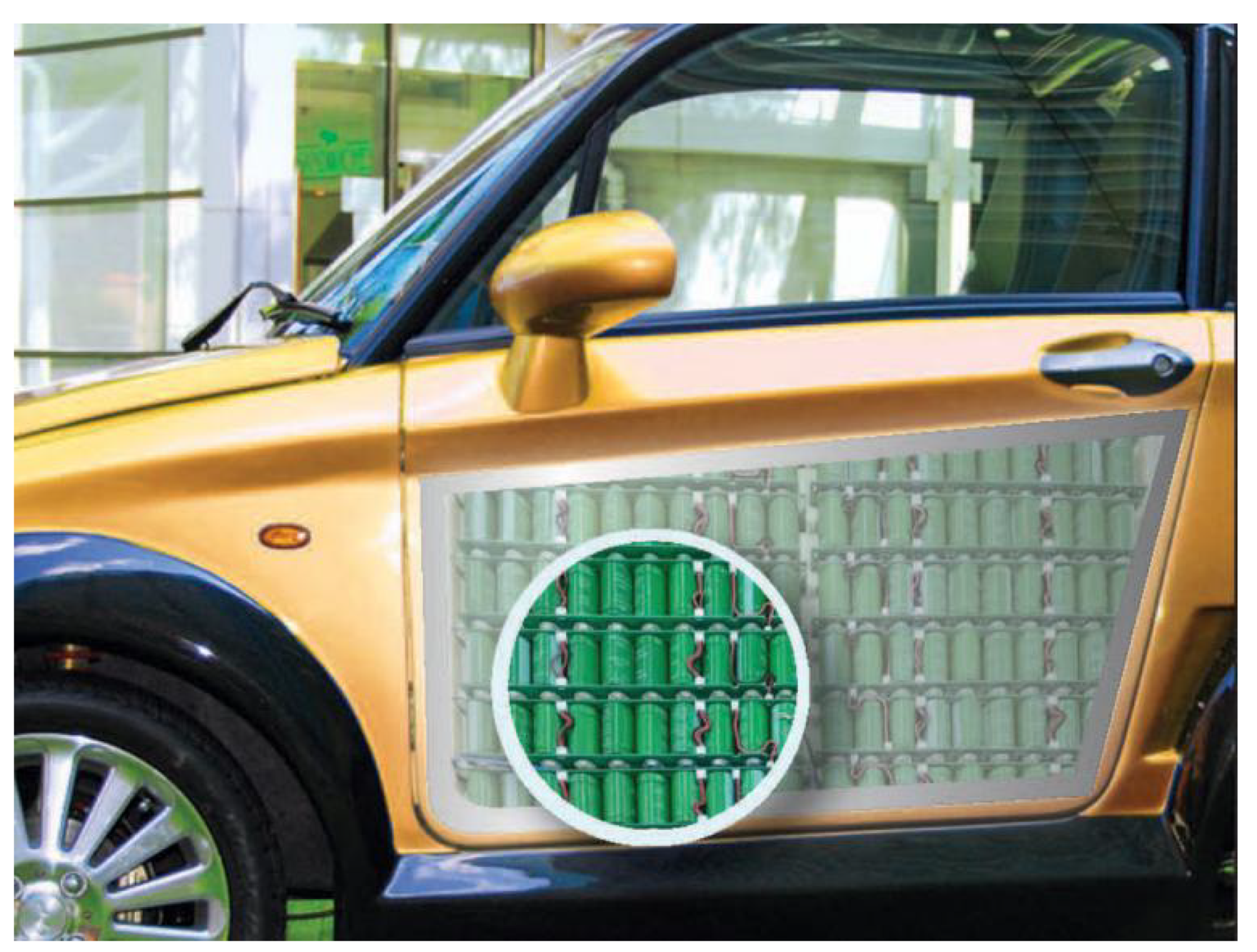
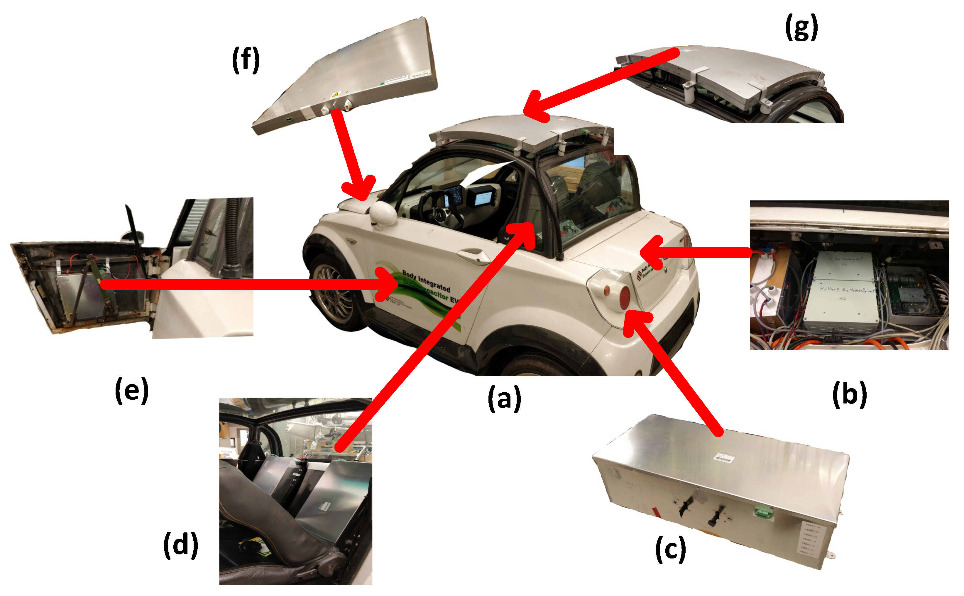
2. Concept of Body Integration

The concept of BISC is shown in Figure 1. Super-capacitor cells are connected in series, called strings, to increase the operating voltage. Many such strings are parallelly connected to enhance the power rating. The panels are connected to an SCMU and covered by an enclosure for protection. The shapes of the BISC panels match a part of the original car body and are smoothly integrated into the bonnet, door, roof or boot lid.
Figure 2a shows the prototype of a BISC car. It features several BISC panels placed on the roof, behind the driver and passenger seats and inside the door and the bonnet. All these panels are connected in parallel. The BIC, battery and SC management systems, VCU and the motor controller are installed in the boot. The primary energy source, a Li-ion battery, is placed beneath the two seats.
In [27], a simulation model of EVs powered by SCs is proposed for determining the acceleration and distance traveled. The BISC panels also have embedded voltage-balancing circuits to equalize individual super-capacitors’ voltages in a string. These balancing circuits augment the operating life of the super-capacitors and alleviate the likelihood of working hazards. Resistive voltage equalizing schemes, as reviewed in [28], are installed in the panel.
Figure 3 shows a BIC interfaced with the BISC and Li-ion battery HESS. The BIC is an ideal choice when the operating current is high and is therefore employed in the HESS. The main drawback for this HESS–converter configuration is that the output voltage of the BIC does not have a wide range as the port is parallel to a voltage source. As in [29,30], loss of the system in Figure 3 is analyzed in detail with a simulation model.

3. Analysis of Energy Storage Devices

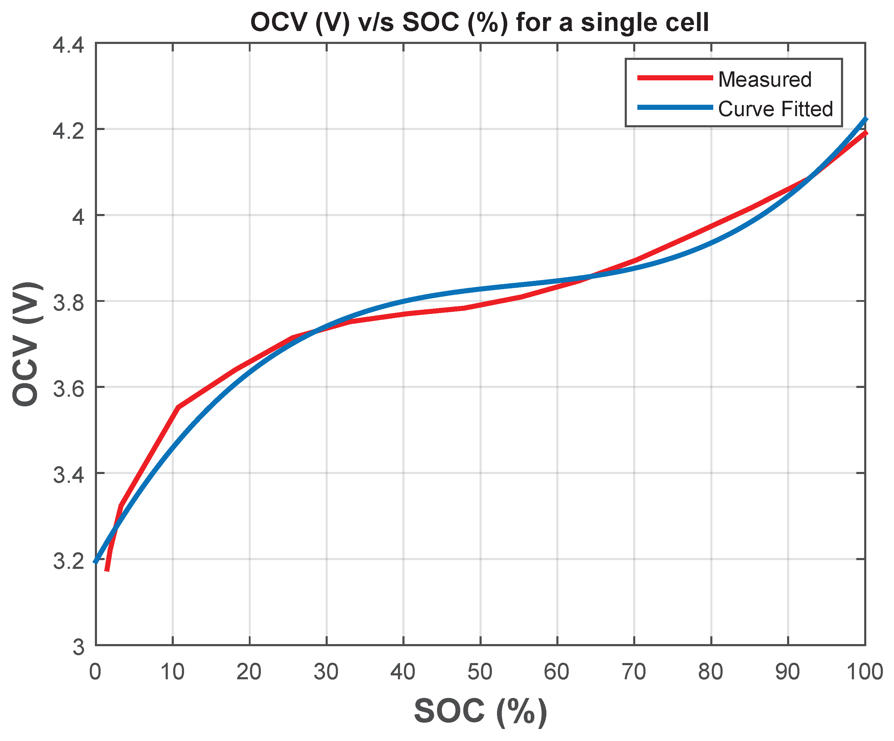
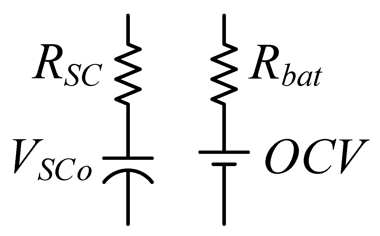
3.1. Li-Ion Polymer Battery

Individual Li-ion NMC cells rated at 3.7 V and 56 Ah are used to characterize the battery of the HESS. The OCV versus SOC curve is obtained as explained in [31,32]. The cell is charged to 100% SOC initially and is discharged for a definite period with a constant current and rested periodically. The discharge current is used calculate the SOC using [33] (1).
S O C ( % ) = 100 × Q r e m Q n o m = 100 × Q n o m I b a t t d i s Q n o m
The measured OCV versus SOC curve is plotted in Figure 4. The characteristic is curve fitted to a third degree polynomial (or a cubic) function given by (2).
O C V ( S O C ) = p 1 S O C 3 + p 2 S O C 2 + p 3 S O C + p 4 p 1 = 3.288 μ , p 2 = 0.5409 m , p 3 = 0.03148 , p 4 = 3.195
The measured internal resistance R b a t at 1 C and 0.5 C is around 3 m Ω from SOC 20% to 90% and around 10 m Ω from SOC 90% to 100%.
Batteries can be modeled utilizing electrochemical [34], electrical circuit [31,32], analytical [35] and stochastic [36] methods. An electrical circuit model utilizes a DC source, R, L and C components to characterize the battery, making them an ideal candidate for electrical simulation. The battery model in this study is intended for a longer duration of operation rather than the RC time constants which are suitable for instant estimation of the power loss associated with the model. Therefore, a simple electrical circuit model with a DC source and a series resistor (characterizing the equivalent resistance of the contact, electrode and the electrolyte) is shown in Figure 5. The rated voltage of the battery pack is 81.4 V and the rated capacity is 112 Ah.

3.2. Super-Capacitor

A single super-capacitor cell of 2.7 V and 350 F is used for characterization. The internal resistance of the super-capacitor is extracted from the experiments as suggested in [37]. The variation in the internal resistance during charging and discharging with current is shown in Figure 6. The DOD of the super-capacitors is given by the equation
D O D = V S C m a x 2 V S C 2 V S C m a x 2 V S C m i n 2
There are several SC models in the literature. In [38], a full frequency-range model of an SC capable of mimicking different phenomena is presented. It consists of several series and parallel RC networks. Several SC electrical circuit models have been reviewed in [39]. For application in this study, a simple model with a series resistance is sufficient to predict the SC behavior. Figure 5 shows the variation in SC ESR with different discharge currents.
A simplified model of a Li-ion cell and a super-capacitor cell including only the series resistance and eliminating the RC networks is given in Figure 6.

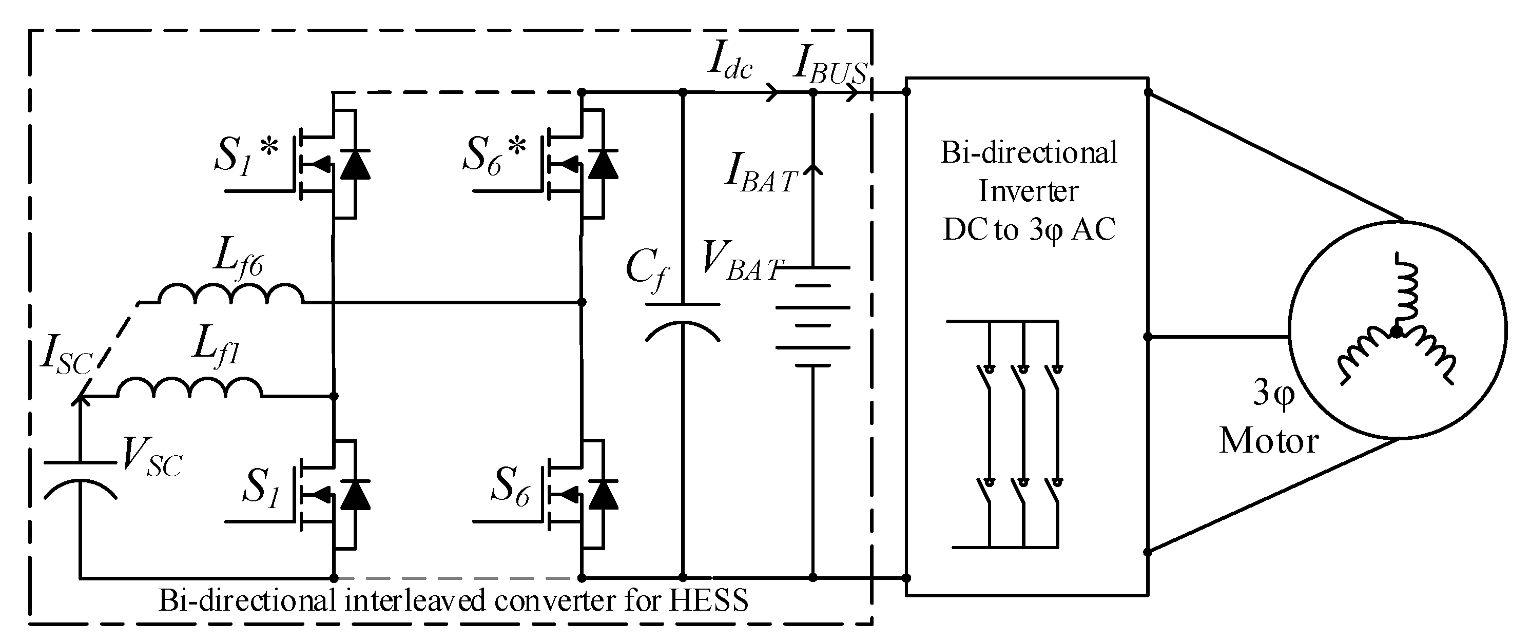
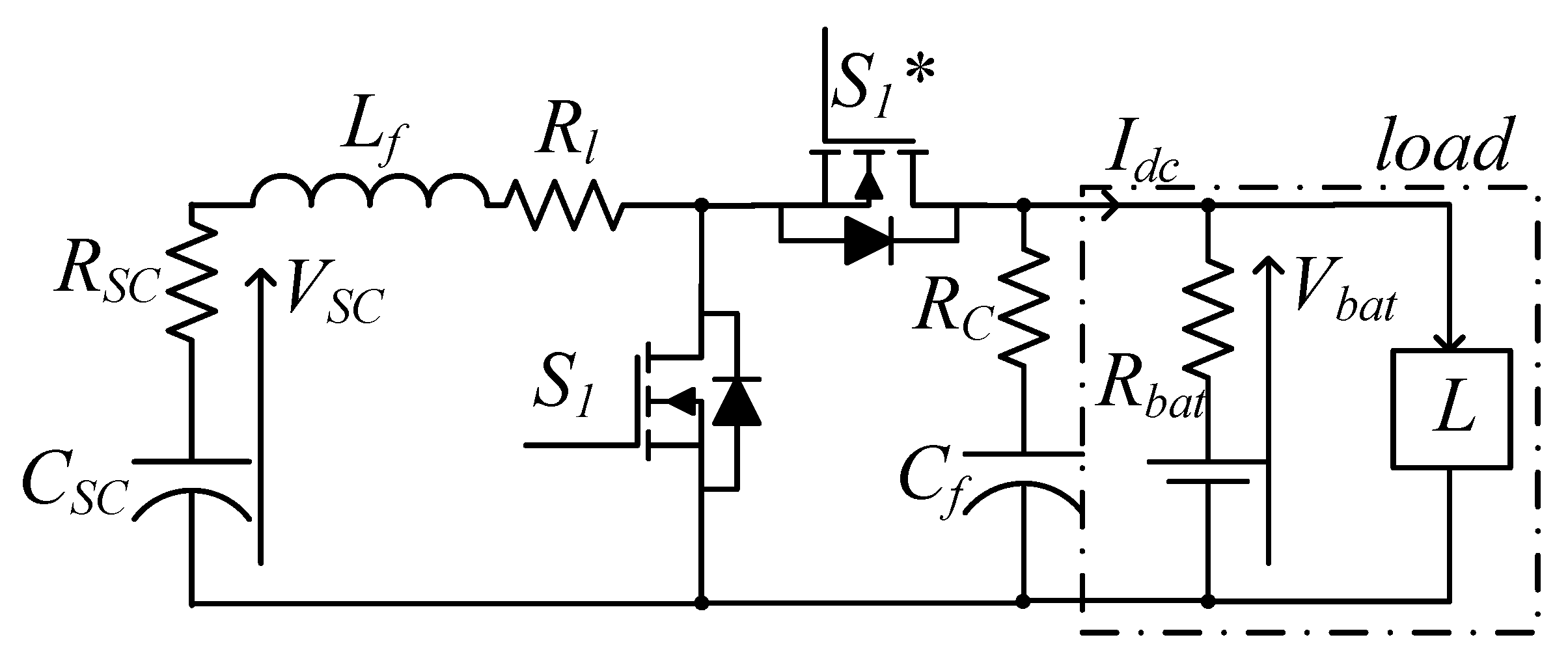
4. Power Converter Analysis

The BIC is connected to the BISC panels to step up or down the voltage during discharging or charging of the SC, respectively, and to fully utilize the large voltage range of the SC. The BIC topology helps switch the current from the SC among all phases equally and aids in optimizing the DC bus ripple by employing interleaving. In addition, during regeneration, interleaving enables smoothing of the SC charging current by minimizing ripple.
The BIC can operate in two modes. Under discharging mode (or motoring), the super-capacitors, along with the battery, will discharge to the load. For analysis, it is assumed that the BIC will operate under CCM. Under charging mode (or regeneration), the energy recovered during regeneration of the 3- ϕ induction motor is used to charge the super-capacitors. The analysis is carried out on a single phase equivalent model of the bi-directional converter shown in Figure 7. The converter is analyzed in both discharging and charging modes in the following subsections.

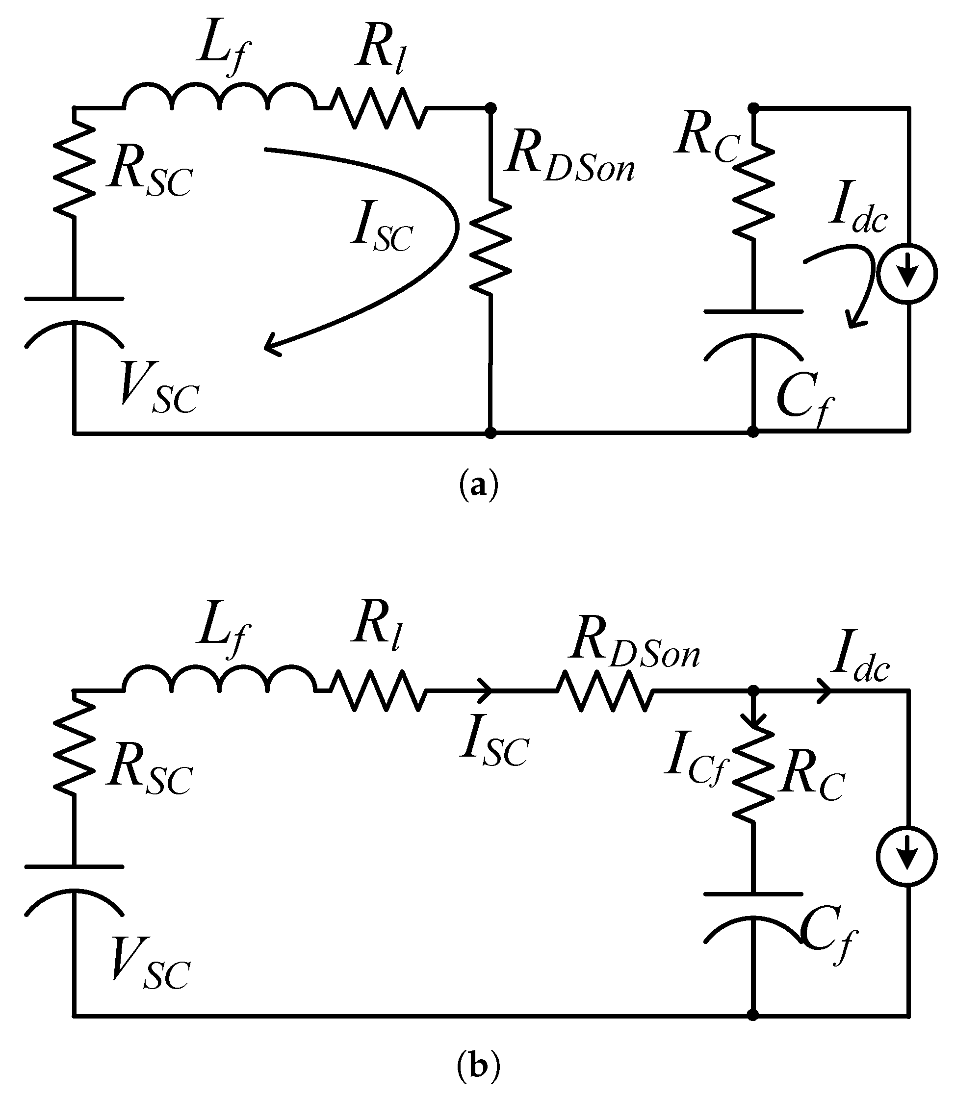
4.1. Discharging Mode Analysis

The discharging mode analysis includes the study of efficiency and steady state characteristics of the BIC. The equivalent states of the single phase boost converter when the MOSFET S 1 is turned ON and OFF are shown in Figure 8a,b, respectively. MOSFET switching loss in a boost converter can be represented as [40]
P s w = f S C 0 V d c 2 = f S C 0 ( I d c R 0 ) 2
From Table 1, the RMS current expression through the switches ( I S 1 ) and the passive components ( L f , C f ) can be obtained. These expressions can be used to derive the respective conduction losses in each component. The efficiency of the converter during discharge ( η d i s ) as a function of parasitics and the duty cycle is given by (6). Efficiency ( η d i s ) in general terms can be given by
η d i s = 1 1 + P L P 0
The net conduction loss can be computed by using the expressions for the different RMS currents in Table 1. The corresponding conduction loss is evaluated using the parasitic resistance. The sum of switching and conduction losses can be expressed as a function of the output power. After re-arranging and substituting in (5), the expression for efficiency during discharge mode ( η d i s ), excluding the inductor core loss, can be simplified to
η d i s = 1 1 + D R D S + R l + R S C R 0 ( 1 D ) 2 + R D S + D R C R 0 ( 1 D ) + 2 f s C 0 R 0
Using the above expression, the steady-state boost voltage gain can be expressed as (7) [16].
M b o o s t = V d c V S C = η d i s 1 D
Figure 9a plots the variation in the steady state voltage gain and the efficiency of the boost converter versus the duty cycle for different R 0 settings. To determine the duty cycle corresponding to the maximum voltage gain, the ratio of the output voltage to the input voltage of the converter is differentiated with respect to the duty ratio and equal to zero, d ( M b o o s t ) d D = 0 . The duty cycle corresponding to maximum voltage gain is given by (8). Efficiency at the maximum steady-state voltage gain ( η D m a x ) can be computed by substituting the value of D m a x from (8) into (6) and is given by (9).
D m a x = R 0 R C ( 2 C 0 f S R 0 2 + R 0 R C ) K + 2 C 0 R 0 2 f S 2 C 0 f S R 0 2 + R 0 R C
η D m a x = R 0 K 2 K R 0 R C + R C 2 C 0 f S R 0 2 + R 0 R C K + 4 C 0 R 0 2 f S K

4.2. Charging or Regenerative Mode

In this section, the charging efficiency of the super-capacitor is described. The energy ( E S C ) stored in the super-capacitor at time t after being charged is given by
E S C = C S C ( V S C 2 ( t ) V S C 2 ( 0 ) ) 2
where C S C is the capacitance in Farad, V S C ( 0 ) is the initial voltage of the super-capacitor before charging. The total energy consumed ( E t o t a l ) during the charging period is given by
E t o t a l = 0 t V b u c k ( t ) I S C ( t ) d t = 0 t V S C ( t ) + I S C ( t ) R S C I S C d t
where V b u c k is the output of the BIC when operating as a buck converter. In this operating mode, the converter charges the super-capacitor. The efficiency can be computed by E S C E t o t a l . The same analysis can be computed for constant current charging
V S C ( t ) = I S C t C S C + V S C ( 0 )
η S C = Δ V S C + V S C ( 0 ) Δ V S C + V S C ( 0 ) + I S C R S C
where Δ V S C = I S C t 2 C S C . From Table 2 and Figure 10, the efficiency of the converter operating during constant charging can be computed, if the regenerative power is known, using (14).
η c h = η b u c k = P d c P L P d c
where the net loss ( P L ) can be reduced to: P L = I S C 2 K + 2 f S C 0 V S C 2 . Figure 11 shows the charging efficiency versus charging current of the BIC simulated for a constant regenerative power of 250 W.
Table 3 gives the specifications of the BIC converter prototype shown in Figure 12.

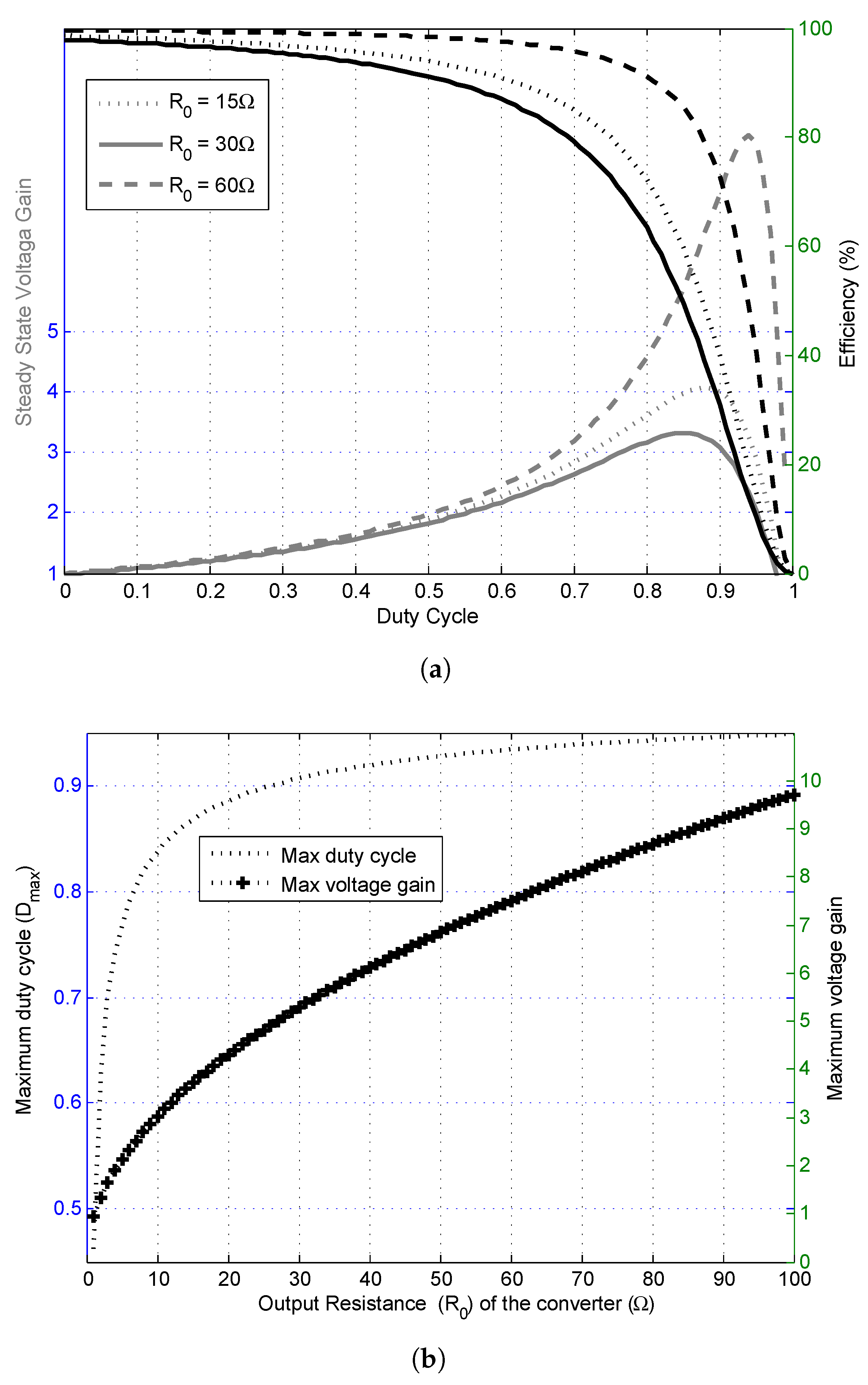
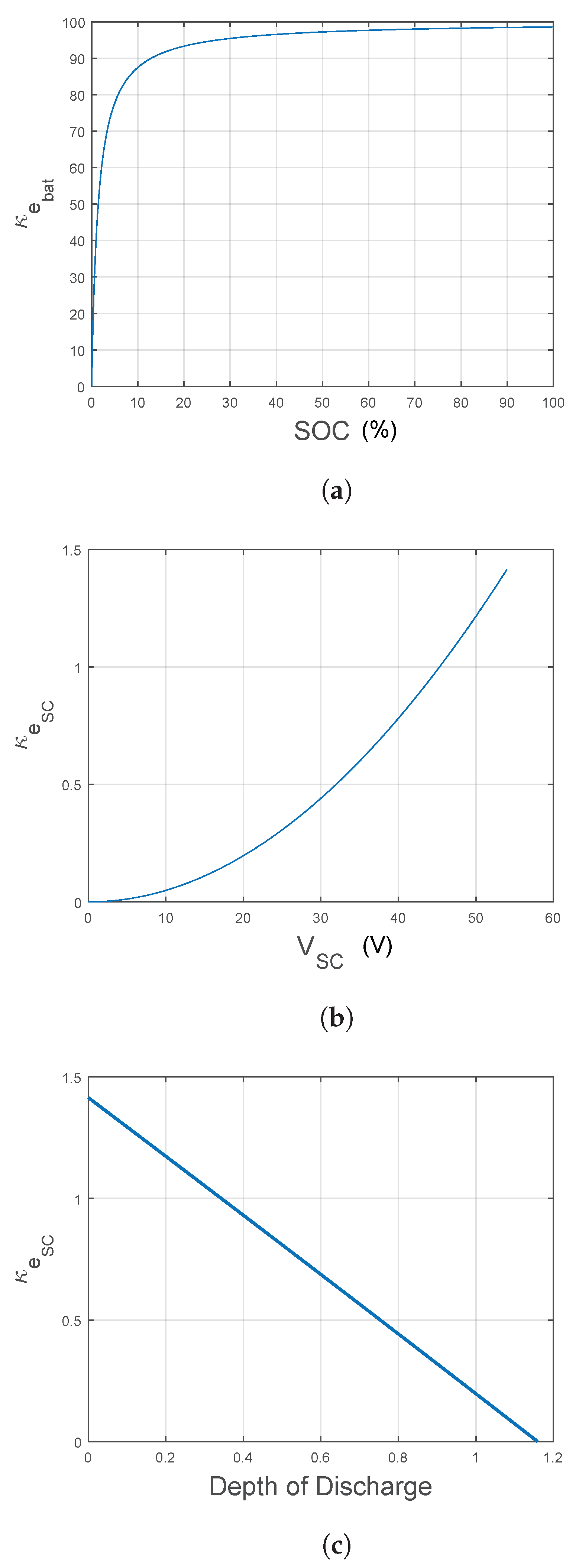
5. Sizing, Design and Performance Indices of the HESS

The data collected by the BSMS [41] calculate the SOC of the battery and super-capacitor pack. The BSMS interfaces with the VCU, battery and SC chargers. Figure 13 outlines the system-level integration in the designed HESS EV. A 5kW three-phase induction motor is driven by an inverter. Both the Li-ion battery and the super-capacitor power the motor. The Li-ion battery is interfaced with the DC bus through a protective relay. All the SC panels also have a protective relay. Individual SC panels are connected in parallel and interfaced with the six-phase bi-directional DC-DC converter. The BMU and SCMU continuously supervise the voltage, current and temperature of cells inside the battery module and SC modules, respectively. Bus voltage, bus current and the insulation resistance are also supervised by the bus monitoring units. Data from the BMU and SCMU are collected by the BSMS to compute the SOC of the battery and SC, and other important parameters. The BSMS interfaces with the charger and the VCU. The VCU provides the supervisory control to turn ON/OFF the BIC, inverter and interfaces with the display unit helping the vehicle driver.
The parameters of the EV prototype are listed in Table 4. The super-capacitor panels are integrated into the car body as shown in Figure 2. An individual super-capacitor cell is rated at 2.7 V and 350 F. Twenty super-capacitor cells are connected in series to form a string. Several strings are connected in parallel to form one BISC pack. Each BISC pack has embedded protection and balancing features. The net capacitance of the installed BISC is equal to 323 F. Each door has a BISC panel of 30 F integrated into its original structure (Figure 2e). BISC panels rated at 65 F are placed behind each of the car seats and one under the bonnet (Figure 2d), and a 98 F curved panel is installed as the roof (Figure 2g). All the BISC panels are rated at 54 V and connected in parallel. The BIC interfaces the BISC panels with the battery and the motor drive as elucidated in Figure 3. The Li-ion polymer battery pack has a voltage rating at 81.4 V and 112 Ah.

Performance Indices

HER is defined as the ratio of the energy stored in the SC ( κ e S C ), or the chemical potential energy in Li-ion battery ( κ e b a t ), to the total energy in the system.
κ e S C = 0.5 C S C V S C 2 0.5 C S C V S C 2 + ( V b a t Q n o m × 3600 )
κ e b a t = V b a t Q n o m × 3600 0.5 C S C V S C 2 + ( V b a t Q n o m × 3600 )
HPPR is defined as the ratio of the peak power delivered/absorbed by the SC ( κ p p S C ), or the battery ( κ p p b a t ), to the peak power demanded by the load. Similarly, HAPR is defined as the ratio of the average power delivered/absorbed by the SC ( κ a p S C ), or the battery ( κ a p b a t ), to the average power demanded by the load. For the HESS in this study, the values of κ e S C and κ e b a t when the SC is fully charged and the battery SOC is 100% are 1.415% and 98.585%. The value of HER changes dynamically as the battery and SC discharge to the load. Intelligent energy management algorithms based on HER can be designed. The variation in κ e b a t and κ e s c is shown in Figure 14. The HPPR and HAPR can be adjusted by the designer, which depends on the energy management algorithm and the application.

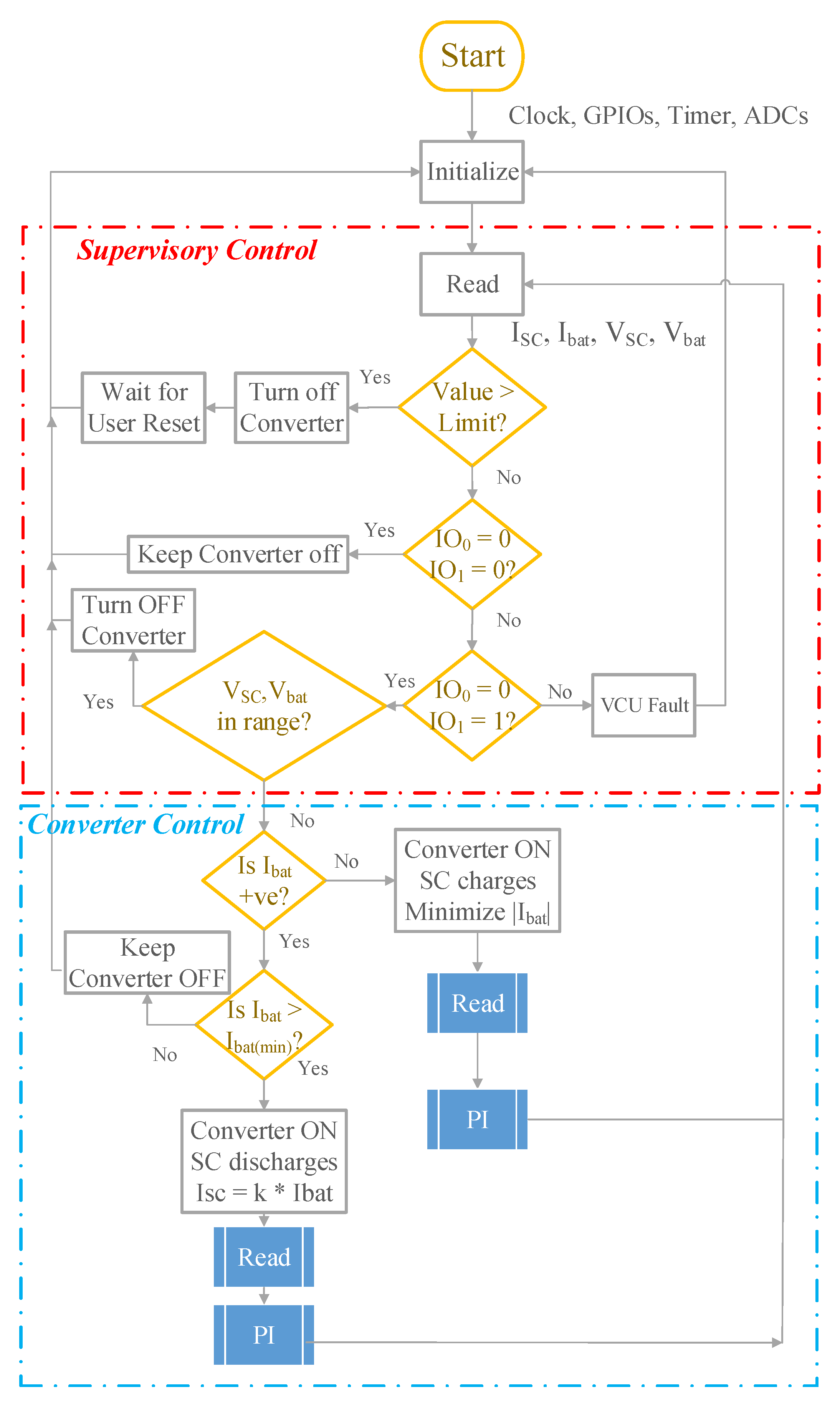
6. Control Strategy and Implementation

Articles [42,43,44,45,46] explore various control strategies. In [42,44], optimal control to minimize HESS losses and prolong battery life is implemented using a power split algorithm. Fuzzy control has been proved for power flow development [47] and is realized to ensure there is minimum variation in the battery current and the losses are minimized in [43]. In [45], Markov’s decision process is used to ensure optimum power allocation between the SC and battery. Similarly, a model predictive technique is employed for active energy management in [46]. These techniques are computationally intensive and require advanced controllers for efficient programming.
In this study, an adaptive PI control technique is employed which can be easily implemented by MCU. That is, the PI parameters values are not fixed but are varied according to the SC voltage. The initial values are set using modeling and simulation.The final values are adjusted by trial and error during the experiments to obtain the desired performance. The controller ensures that during acceleration and braking, more current is delivered/absorbed by the SC, respectively, thereby preventing the battery from degrading faster. This is carried out by optimally tuning the controller to react faster.
A simple energy management system to share the demanded power through super-capacitors and a Li-ion battery is presented in Figure 15. The VCU supervises all the subsystems in the car including the converter. After initialization, important parameters of the converter V S C , V b a t , I S C and I b a t are read to ensure they are under the limits. If any of the parameters exceed the threshold value, the converter is immediately turned off. Upon receiving the signal from the VCU, the converter measures the battery current I b a t to determine if the vehicle is motoring or regenerating.
If the vehicle is motoring, i.e., I b a t is positive, the super-capacitor discharges through the BIC and shares the demanded power. The value of the controlled super-capacitor current I S C is set by the user. A threshold value of I b a t is set to decide when the converter should operate, for both charging and discharging operations. The parameters that determine the threshold value include the load current, DOD of the super-capacitor modules and SOC of the Li-ion battery pack. During discharging, the objective is to maintain the super-capacitor’s current at the reference value. This is achieved by using a PI controller. If the vehicle is regenerating, i.e., I b a t is negative, the BIC operates as a buck converter and charges the super-capacitor. During regeneration, the objective is to minimize I b a t and increase the super-capacitor charging current. Therefore, the controller is programmed to operate the converter such that the current is 90% of the maximum allowed current.
The design of the vehicle has to take care of the inverter design. The multi-level inverter based on multiple battery cells is a good attempt [48]. All the wiring, including the power distribution and the magnetic components, the multi-stranded design, should be followed [49].

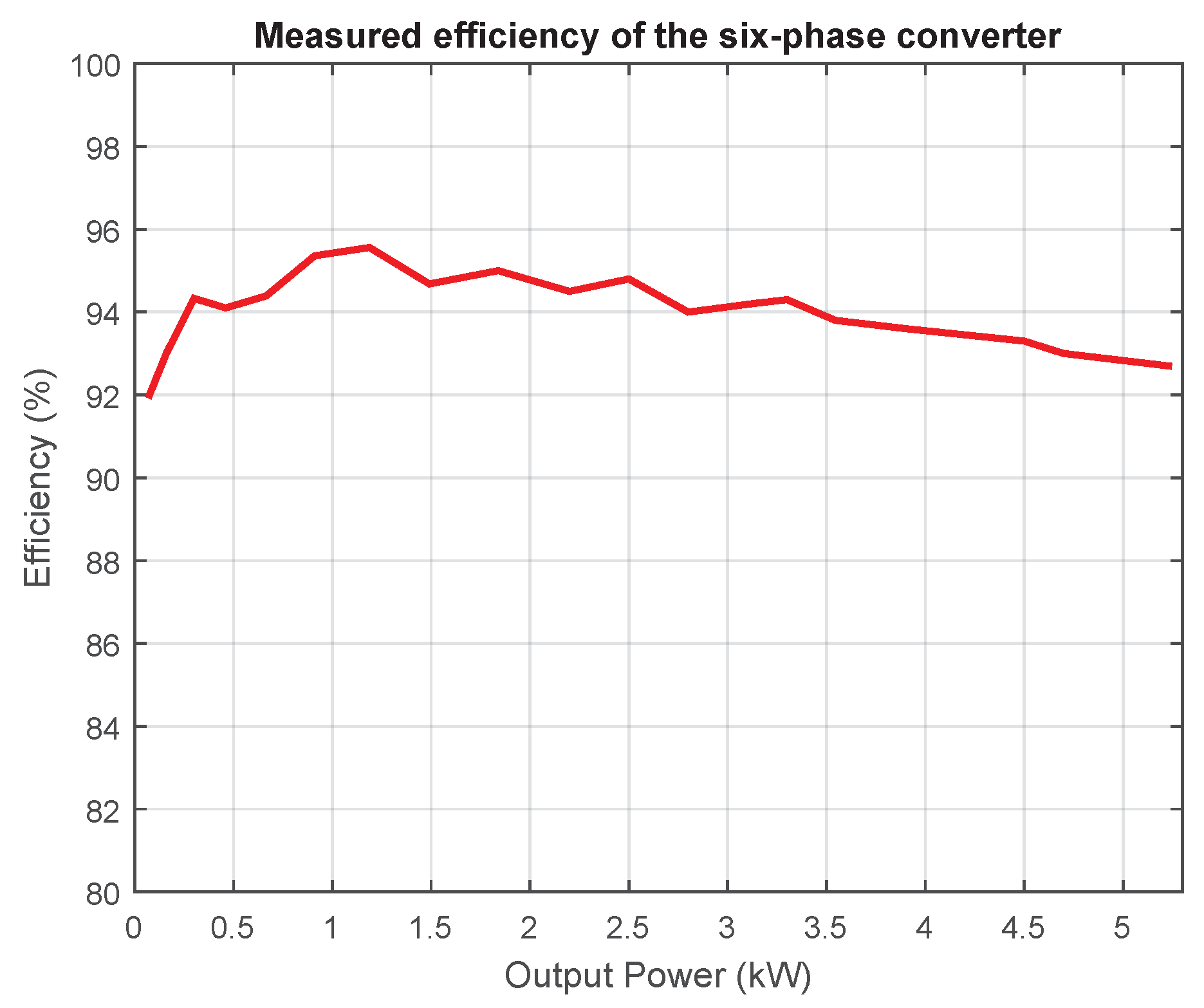
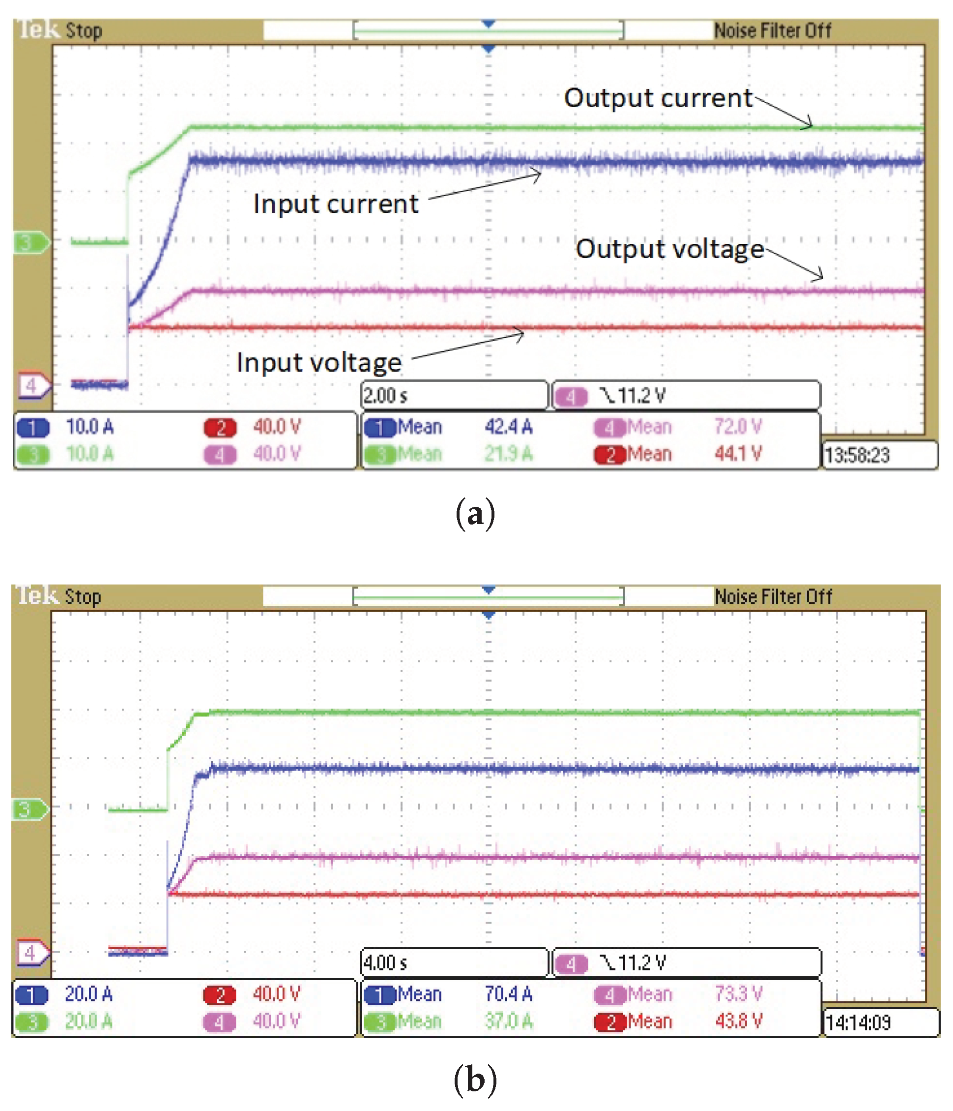
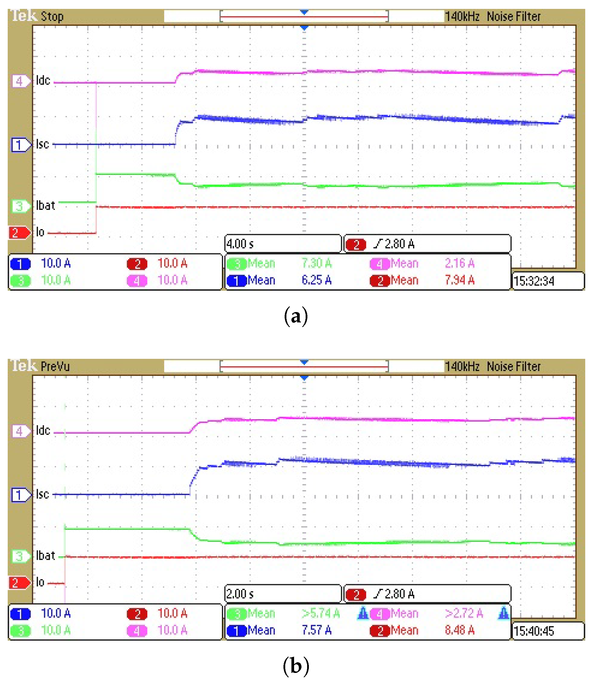
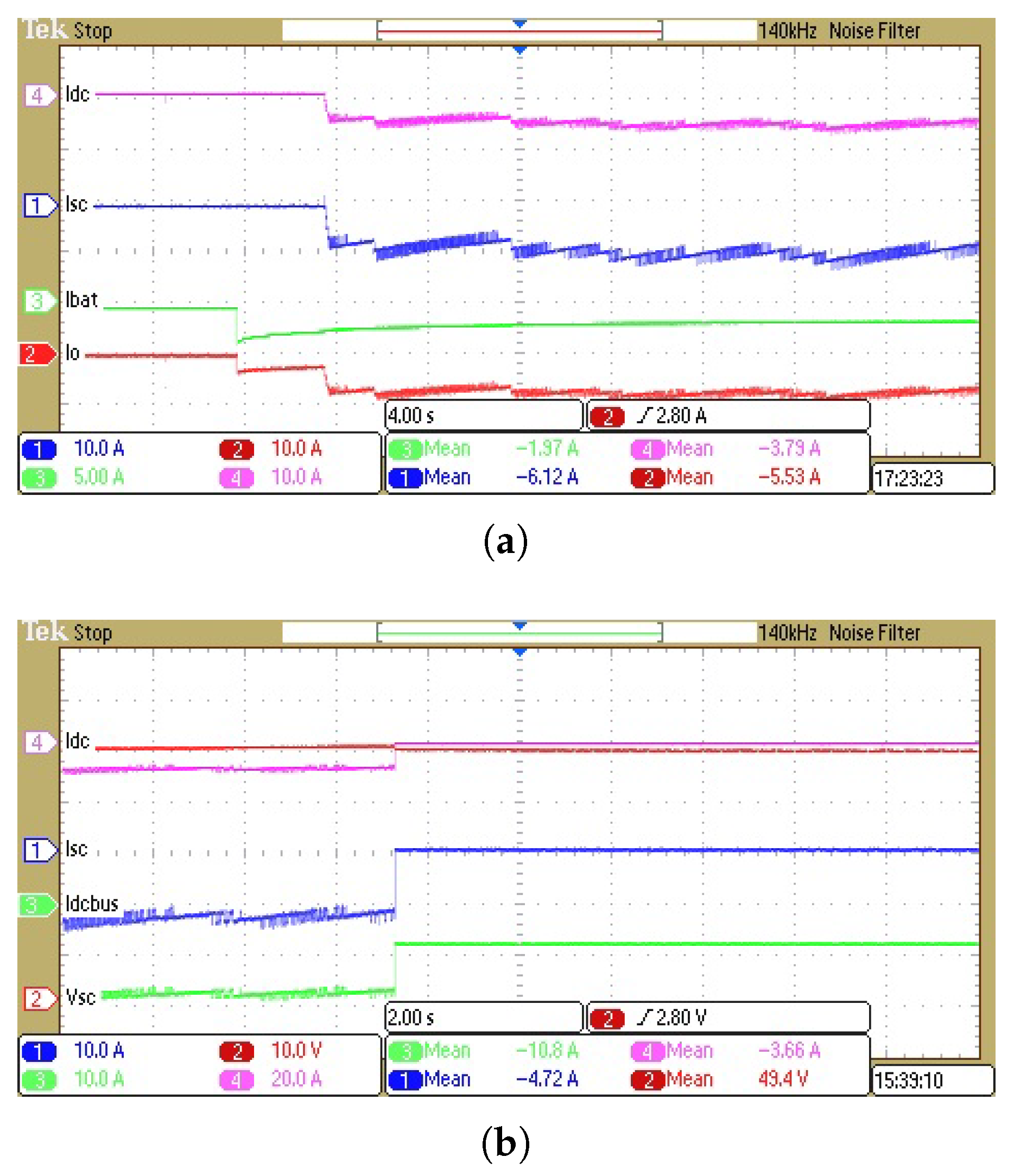
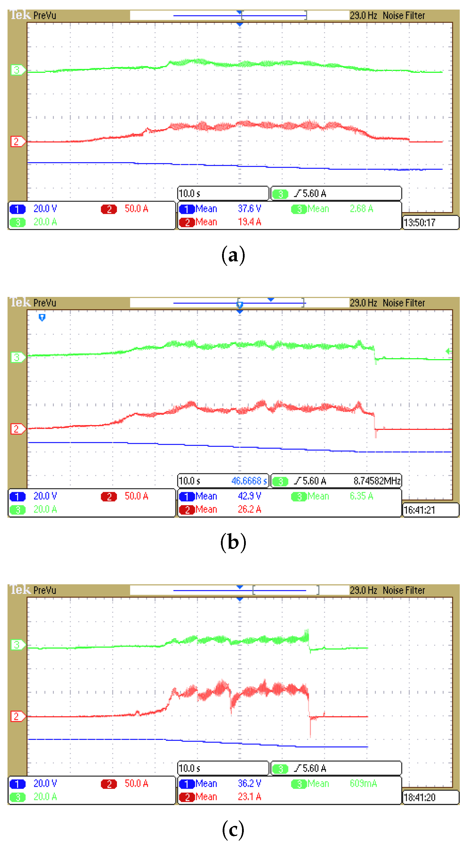
7. Results and Discussion

At heavy load, all phases (six in this case) are active and share the current to obtain higher efficiency (Figure 16). When the load becomes light, the power processed by each phase is significantly reduced. If all the phases are still operating, the switching loss conduction loss, inductor core loss, etc. still exist in all channels. This makes it relatively inefficient. During higher power operation, the increase in conduction losses and switching losses causes the efficiency to reduce. The light load efficiency can be improved by active phase shedding algorithm.Test results to certify the working of the BIC using DC supplies (Figure 10) is shown in Figure 17. A PI controller is programmed in STM32 to govern the current to a set value. Furthermore, the current control algorithm helps in minimizing the inrush current which is vital in SC systems. Figure 17a,b depicts the VI input and output waveforms of the BIC operating with a set current of 45 A and 80 A.
First, experiments using BISC panels and lead–acid batteries (92 V, 12 A) are carried out. Figure 18a,b depicts the SC discharging test with the battery current( I b a t ) regulated to 1.5 times and equal to the BIC output current, respectively. At the beginning, only the battery is discharged, and when the BIC reads the discharge command from the VCU, the BIC is controlled such that the desired value of the BIC output current is realized.
SC charging test results are depicted in Figure 19. Figure 19a shows the 10 A constant current charging waveform. At the beginning, the regenerative current charges the battery alone and waits for the instruction from the VCU. Upon receiving the instruction, the SC begins to become charged while the controller regulates the charging current to 10 A. Figure 19b depicts the over-voltage safety feature of the BISC panels. When the SC charges up to the cut-off voltage (50 V), the converter turns off, forcing the regenerated current to only charge the battery.
Test results of an HESS (BISC panels and Li-ion battery) powering a 5kW, 3-phase induction motor installed on an EV are shown in Figure 20. In Figure 20, the motor is started from rest until the prototype EV reaches a certain speed. Once the EV reaches the set speed, the driver tries to maintain the speed for a brief period and releases the accelerator pedal thereafter. The waveforms in Figure 20a–c show the experiment at 15 kmph, 20 kmph and 25 kmph, respectively. The super-capacitor voltage, super-capacitor current and battery current are measured. It is seen that the average SC current is at least four times higher than the average battery current. The ratio of the currents can be further adjusted based on the driving cycle and pattern. It can clearly be seen that the response of the SC to the load demand is quicker when compared to the battery. This ensures that during start-up, the battery is less exposed to the motor’s high power demand, which improves the battery life in the long run. During braking, most of the regenerated power (although the magnitude is small in the examples in Figure 20b,c) is transferred to the SC. This again protects the battery from the spiky charging current.
Operating waveforms of the BIC under both discharging and charging scenarios are presented. Experimental results of the super-capacitor and battery current when the vehicle is started from standstill, reaches a certain speed and halts shows that the designed vehicle functions well. The Li-ion battery is protected during both the start-up and braking operation. During the vehicle start-up, the SC responds relatively quickly to the load demand by discharging a higher current in a shorter time. Similarly, during braking, most of the regenerated power is fed to the SC, thereby protecting the battery from spiky currents. Both of these characteristics help improve the battery life effectively [18].

8. Conclusions

The paper presents the analyses of a BISC and the developed BIC. The system is integrated into an existing Li-ion battery-powered electric drive train. Measurements of the converter, model of the Li-ion battery used and super-capacitor based on experimental data, results of the hybrid energy storage system with a simple energy management and control are illustrated.
The concept of body integration is illustrated with examples from the developed system. Body parts of the EV are fitted with SC panels which match the shape. The BISC panels are equipped with protection and passive balancing features, making them safe. The door, bonnet, roof and space behind vehicle seats are fitted with SC panels, utilizing the available space effectively in order to share the packaging between the SC and the vehicle body.
A simplified model of a single cell of both a Li-ion battery and SC is presented. Since the objective of the study is to use significantly larger time constants than the second and third order RC networks in electrical circuit models, a simplified model with only a series resistor is studied. Additionally, the series resistance is also larger in magnitude in comparison to the resistors in the RC network and therefore accounts for the maximum power loss.
The BIC is studied under both SC discharging mode and charging mode, i.e., the converter is operating in voltage-boost mode or in voltage-buck mode. The relationships between duty cycle, efficiency and the converter gain give the designer valuable information. Overall system efficiency can be improved by operating the converter only during certain conditions, as required.
The system design of the vehicle is presented. Features and functions of the BSMS, VCU, the HESS, DC-DC converter and inverter are clearly explained. The proposed system is stable and it can be controlled by a simple energy management technique to share the power demanded by the inverter. PI control is able to be used to implement the energy management strategy with reference parameters set by the user.
The proposed work prepares for a configurable electric vehicle as the energy storage can be installed in different locations of a vehicle, instead of the energy storage being fixed in a single energy storage compartment. The energy storage in a distributed format facilitates the smart and innovative design of electric vehicles and will form a new concept of electric vehicle application.

Author Contributions

Hardware design, software and validation: S.R.R., Y.-C.F. and X.-D.X.; Paper writing: S.R.R.; Conceptualization: K.-W.C.; Supervision and project administration: K.-W.C.; Battery system design and support: S.C. All authors have read and agreed to the published version of the manuscript.

Funding

This work was supported by ITF, the APAS R&D centre, Man Yue Electronics Company Limited and EV Dynamics Limited under Project GHP/057/14AP.

Conflicts of Interest

The authors declare no conflict of interest.

Abbreviations

The following abbreviations and symbols are used in this manuscript:
EDLCElectric double layer capacitors
ESDEnergy storage device
EVElectric vehicle
SCSuper-capacitor
BISCBody integrated super-capacitor
CCMContinuous current mode
BICBi-directional interleaved converter
SOCState-of-charge
HESSHybrid energy storage system
OCVOpen circuit voltage
DODDepth of discharge
BMSBattery management system
SCMSSuper-capacitor management system
VCUVehicular controller unit
SCMUSuper-capacitor management unit
BMUBattery management unit
PVPhoto-voltaic
V b a t Battery voltage (V)
I b a t Battery current (A)
R b a t Battery series resistance ( Ω )
t d i s Discharge period (s)
Q n o m Nominal capacity (Ah)
Q r e m Remaining capacity (Ah)
V S C Super-capacitor voltage (V)
C S C Capacitance of SC (F)
I S C Super-capacitor current (A)
R S C Super-capacitor internal resistance ( Ω )
E S C Energy stored in the SC (J)
V d c BIC output voltage (V)
I d c BIC output current (A)
L f Filter inductance (H)
R l Series resistance of inductor ( Ω )
I L Inductor current (A)
R 0 BIC output resistance during discharge ( Ω )
C 0 Linear output capacitance of MOSFET (F)
DDuty cycle of the converter
f S Switching frequency of the converter (Hz)
C f Filter capacitances (F)
R C Series resistance of capacitor ( Ω )
S 1 Low side MOSFET
S 1 * High side MOSFET
R D S MOSFET on-state resistance ( Ω )
η Efficiency
P L Net power loss (W)
P 0 Output power (W)
P s w Switching loss (W)
K R D S + R l + R S C ( Ω )
E t o t a l Total energy consumed (J)
V b u c k Buck mode output voltage (V)

References

  1. Khaligh, A.; Li, Z. Battery, ultracapacitor, fuel cell, and hybrid energy storage systems for electric, hybrid electric, fuel cell, and plug-in hybrid electric vehicles: State of the art. IEEE Trans. Veh. Technol. 2010, 59, 2806–2814. [Google Scholar] [CrossRef]
  2. Emadi, A.; Williamson, S.S.; Khaligh, A. Power electronics intensive solutions for advanced electric, hybrid electric, and fuel cell vehicular power systems. IEEE Trans. Power Electron. 2006, 21, 567–577. [Google Scholar] [CrossRef]
  3. Li, W.; Joós, G.; Bélanger, J. Real-Time Simulation of a Wind Turbine Generator Coupled With a Battery Supercapacitor Energy Storage System. IEEE Trans. Ind. Electron. 2010, 57, 1137–1145. [Google Scholar] [CrossRef]
  4. Wu, D.; Williamson, S.S. A novel design and feasibility analysis of a fuel cell plug-in hybrid electric vehicle. In Proceedings of the Vehicle Power and Propulsion Conference, VPPC’08, Harbin, China, 3–5 September 2008; pp. 1–5. [Google Scholar]
  5. Ise, T.; Kita, M.; Taguchi, A. A hybrid energy storage with a SMES and secondary battery. IEEE Trans. Appl. Supercond. 2005, 15, 1915–1918. [Google Scholar] [CrossRef]
  6. Prodromidis, G.N.; Coutelieris, F.A. Simulations of economical and technical feasibility of battery and flywheel hybrid energy storage systems in autonomous projects. Renew. Energy 2012, 39, 149–153. [Google Scholar] [CrossRef]
  7. Mourembles, D.; Buergler, B.; Gajewski, L.; Cooke, A.; Barchasz, C. Li-S Cells for Space Applications (LISSA). In Proceedings of the European Space Power Conference (ESPC), Juan-les-Pins, France, 30 September–4 October 2019. [Google Scholar]
  8. Scrosati, B.; Garche, J. Lithium batteries: Status, prospects and future. J. Power Sources 2010, 195, 2419–2430. [Google Scholar] [CrossRef]
  9. Jayakumar, A.; Chalmers, A.; Lie, T.T. Review of prospects for adoption of fuel cell electric vehicles in New Zealand. IET Electr. Syst. Transp. 2017, 7, 259–266. [Google Scholar] [CrossRef]
  10. Simon, P.; Gogotsi, Y.; Dunn, B. Where do batteries end and supercapacitors begin? Science 2014, 343, 1210–1211. [Google Scholar] [CrossRef] [Green Version]
  11. Liu, C.; Yu, Z.; Neff, D.; Zhamu, A.; Jang, B.Z. Graphene-based supercapacitor with an ultrahigh energy density. Nano Lett. 2010, 10, 4863–4868. [Google Scholar] [CrossRef] [PubMed]
  12. Raman, S.R.; Fong, Y.C.; Fan, Y.; Xue, X.D.; Cheng, K.W.E. Development of a light electric car with body integrated super capacitors. In Proceedings of the 7th International Conference on Power Electronics Systems and Applications-Smart Mobility, Power Transfer & Security (PESA), Hong Kong, China, 12–14 December 2017; pp. 1–7. [Google Scholar]
  13. Li, J.; Xiong, R.; Mu, H.; Cornélusse, B.; Vanderbemden, P.; Ernst, D.; Yuan, W. Design and real-time test of a hybrid energy storage system in the microgrid with the benefit of improving the battery lifetime. Appl. Energy 2018, 218, 470–478. [Google Scholar] [CrossRef] [Green Version]
  14. Paul, T.; Mesbahi, T.; Durand, S.; Flieller, D.; Uhring, W. Sizing of Lithium-Ion Battery/Supercapacitor Hybrid Energy Storage System for Forklift Vehicle. Energies 2020, 13, 4518. [Google Scholar] [CrossRef]
  15. Alvaro, D.; Arranz, R.; Aguado, J.A. Sizing and operation of hybrid energy storage systems to perform ramp-rate control in PV power plants. Int. J. Electr. Power Energy Syst. 2019, 107, 589–596. [Google Scholar] [CrossRef]
  16. Cheng, K. Classical Switched-Mode and Resonant Power Converters; The Hong Kong Polytechnic University: Hong Kong, 2002. [Google Scholar]
  17. Cheng, K.W.E.; Evans, P.D. Parallel-mode extended-period quasiresonant convertor. IEE Proc. B 1991, 138, 243–251. [Google Scholar] [CrossRef]
  18. Ye, Y.; Cheng, K.W.E. An automatic switched-capacitor cell balancing circuit for series-connected battery strings. Energies 2016, 9, 138. [Google Scholar] [CrossRef] [Green Version]
  19. Wang, M.; Tan, S.; Lee, C.; Hui, S.Y. A Configuration of Storage System for DC Microgrids. IEEE Trans. Power Electron. 2018, 33, 3722–3733. [Google Scholar] [CrossRef]
  20. Chan, H.; Cheng, K.W.E.; Sutanto, D. Phase-shift controlled DC-DC converter with bi-directional power flow. IEE Proc. Electr. Power Appl. 2001, 148, 193–201. [Google Scholar] [CrossRef]
  21. Nazir, M.; Ahmad, I.; Khan, M.J.; Ayaz, Y.; Armghan, H. Adaptive Control of Fuel Cell and Supercapacitor Based Hybrid Electric Vehicles. Energies 2020, 13, 5587. [Google Scholar] [CrossRef]
  22. Passalacqua, M.; Carpita, M.; Gavin, S.; Marchesoni, M.; Repetto, M.; Vaccaro, L.; Wasterlain, S. Supercapacitor Storage Sizing Analysis for a Series Hybrid Vehicle. Energies 2019, 12, 1759. [Google Scholar] [CrossRef] [Green Version]
  23. Castano, S.; Gauchia, L.; Sanz-Feito, J. Effect of Packaging on Supercapacitors Strings Modeling: Proposal of Functional Unit Defined Around Balancing Circuit. IEEE Trans. Components Packag. Manuf. Technol. 2013, 3, 1390–1398. [Google Scholar] [CrossRef]
  24. Song, B.; Moon, K.S.; Wong, C.P. Recent Developments in Design and Fabrication of Graphene-Based Interdigital Micro-Supercapacitors for Miniaturized Energy Storage Devices. IEEE Trans. Components Packag. Manuf. Technol. 2016, 6, 1752–1765. [Google Scholar] [CrossRef]
  25. Cheng, K.W.E. Energy Storage, Fuel Cell and Electric Vehicle Technology. In Proceedings of the 8th International Conference on Power Electronics Systems and Applications (PESA), Hong Kong, China, 7–10 December 2020. [Google Scholar]
  26. Chang, A.S.F.; Kalawsky, R.S. Future configurable transport for the ageing population. In Proceedings of the 7th International Conference on Power Electronics Systems and Applications—Smart Mobility, Power Transfer & Security (PESA), Hong Kong, China, 12–14 December 2017. [Google Scholar]
  27. Xue, X.; Cheng, K.W.E.; Raman, S.R.; Chan, J.; Mei, J.; Xu, C. Performance prediction of light electric vehicles powered by body-integrated super-capacitors. In Proceedings of the International Conference on Electrical Systems for Aircraft, Railway, Ship Propulsion and Road Vehicles & International Transportation Electrification Conference (ESARS-ITEC), Toulouse, France, 2–4 November 2016; pp. 1–6. [Google Scholar]
  28. Raman, S.R.; Xue, X.D.; Cheng, K.W.E. Review of charge equalization schemes for Li-ion battery and super-capacitor energy storage systems. In Proceedings of the IEEE International Conference on Advances in Electronics, Computers and Communications (ICAECC), Bangalore, India, 10–11 October 2014; pp. 1–6. [Google Scholar]
  29. Xue, X.; Raman, S.R.; Fong, Y.C.; Cheng, K.W.E. Loss analysis of hybrid battery-supercapacitor energy storage system in EVs. In Proceedings of the 7th International Conference on Power Electronics Systems and Applications-Smart Mobility, Power Transfer & Security (PESA), Hong Kong, China, 12–14 December 2017; pp. 1–6. [Google Scholar]
  30. Xue, X.; Cheng, K.W.E.; Raman, S.R.; Fong, Y.C.; Wang, X. Investigation of energy distribution and power split of hybrid energy storage systems in electric vehicles. In Proceedings of the International Symposium on Electrical Engineering (ISEE), Hong Kong, China, 14 December 2016; pp. 1–7. [Google Scholar]
  31. Raman, S.R.; Saritha, B.; John, V. Computationally efficient and accurate modeling of Li-ion battery. In Proceedings of the Innovative Smart Grid Technologies-Asia (ISGT Asia), Bangalore, India, 10–13 November 2013; pp. 1–6. [Google Scholar]
  32. Saxena, S.; Raman, S.R.; Saritha, B.; John, V. A novel approach for electrical circuit modeling of Li-ion battery for predicting the steady-state and dynamic I–V characteristics. Sādhanā 2016, 41, 479–487. [Google Scholar] [CrossRef] [Green Version]
  33. Cheng, K.W.E.; Divakar, B.; Wu, H.; Ding, K.; Ho, H.F. Battery-management system (BMS) and SOC development for electrical vehicles. IEEE Trans. Veh. Technol. 2011, 60, 76–88. [Google Scholar] [CrossRef]
  34. Dees, D.W.; Battaglia, V.S.; Bélanger, A. Electrochemical modeling of lithium polymer batteries. J. Power Sources 2002, 110, 310–320. [Google Scholar] [CrossRef]
  35. Rakhmatov, D.; Vrudhula, S.; Wallach, D.A. A model for battery lifetime analysis for organizing applications on a pocket computer. IEEE Trans. Very Large Scale Integr. VLSI Syst. 2003, 11, 1019–1030. [Google Scholar] [CrossRef]
  36. Panigrahi, D.; Chiasserini, C.; Dey, S.; Rao, R.; Raghunathan, A.; Lahiri, K. Battery life estimation of mobile embedded systems. In Proceedings of the VLSI Design 2001, Fourteenth International Conference on VLSI Design, Bangalore, India, 7 January 2001; pp. 57–63. [Google Scholar]
  37. Procedures for Capacitance, ESR, Leakage Current and Self-Discharge Characterizations of Ultracapacitors—Application Note; Maxwell Technologies: San Diego, CA, USA, 2015.
  38. Musolino, V.; Piegari, L.; Tironi, E. New full-frequency-range supercapacitor model with easy identification procedure. IEEE Trans. Ind. Electron. 2013, 60, 112–120. [Google Scholar] [CrossRef]
  39. Zhang, L.; Hu, X.; Wang, Z.; Sun, F.; Dorrell, D.G. A review of supercapacitor modeling, estimation, and applications: A control/management perspective. Renew. Sustain. Energy Rev. 2018, 81, 1868–1878. [Google Scholar] [CrossRef]
  40. Kazimierczuk, M.K. Pulse-Width Modulated DC-DC Power Converters; John Wiley & Sons: Hoboken, NJ, USA, 2015. [Google Scholar]
  41. Xue, X.; Fan, Y.; Fong, Y.; Raman, S.R.; Mei, J.; Wang, X.; Cheng, K. Development of Battery-Supercapacitor Management System for Battery-Supercapacitor Hybrid Energy Storage System. In Proceedings of the 11th IET International Conference on Advances in Power System Control, Operation and Management(APSCOM), Hong Kong, China, 11–15 November 2018. [Google Scholar]
  42. Shen, J.; Khaligh, A. A Supervisory Energy Management Control Strategy in a Battery/Ultracapacitor Hybrid Energy Storage System. IEEE Trans. Transp. Electrif. 2015, 1, 223–231. [Google Scholar] [CrossRef]
  43. Yin, H.; Zhou, W.; Li, M.; Ma, C.; Zhao, C. An Adaptive Fuzzy Logic-Based Energy Management Strategy on Battery/Ultracapacitor Hybrid Electric Vehicles. IEEE Trans. Transp. Electrif. 2016, 2, 300–311. [Google Scholar] [CrossRef]
  44. Akar, F.; Tavlasoglu, Y.; Vural, B. An Energy Management Strategy for a Concept Battery/Ultracapacitor Electric Vehicle With Improved Battery Life. IEEE Trans. Transp. Electrif. 2017, 3, 191–200. [Google Scholar] [CrossRef]
  45. Li, G.; Yang, Z.; Li, B.; Bi, H. Power allocation smoothing strategy for hybrid energy storage system based on Markov decision process. Appl. Energy 2019, 241, 152–163. [Google Scholar] [CrossRef]
  46. Zhang, S.; Xiong, R.; Sun, F. Model predictive control for power management in a plug-in hybrid electric vehicle with a hybrid energy storage system. Appl. Energy 2017, 185, 1654–1662. [Google Scholar] [CrossRef]
  47. Rathi, M.; Prabha, N. Interval type-2 fuzzy logic controller-based multi-level shunt active power line conditioner for harmonic mitigation. Int. J. Fuzzy Syst. 2019, 21, 104–114. [Google Scholar] [CrossRef]
  48. Cheng, K.W.E. Computation of the AC Resistance of Multistranded Conductor Inductors with Multilayers for High Frequency Switching Converters. IEEE Trans. Magn. 2000, 36, 831–834. [Google Scholar] [CrossRef] [Green Version]
  49. Raman, S.R.; Cheng, K.W.E.; Ye, Y. Multi-Input Switched-Capacitor Multilevel Inverter for High-Frequency AC Power Distribution. IEEE Trans. Power Electron. 2018, 33, 5937–5948. [Google Scholar] [CrossRef]
Figure 1. Concept of body integrated super-capacitors.
Energies 14 06553 g001
Figure 2. (a) Prototype of the body integrated super-capacitor car: (b) DC-DC converter, BMS, SCMS, VCU and motor drive installed in the boot. BISC panels (c) placed behind the seats and under the hood, 65 F, 54 V, (d) placed behind the seats, (e) placed inside the door, (f) designed to be the bonnet, (g) placed over the roof.
Energies 14 06553 g002
Figure 3. Hybrid energy storage system using bi-directional interleaved converter.
Energies 14 06553 g003
Figure 4. Measured and curved fit plots of OCV versus SOC of a Li-ion polymer cell.
Energies 14 06553 g004
Figure 5. Variation in the super-capacitor equivalent series resistance with current during both discharging and charging.
Energies 14 06553 g005
Figure 6. Simplified model of super-capacitor and the Li-ion polymer battery.
Energies 14 06553 g006
Figure 7. Single phase equivalent model of converter, highlighting parasitics for loss estimation.
Energies 14 06553 g007
Figure 8. Bi-directional converter operation during discharging mode operating as a boost converter. (a) Switch S 1 ON ( 0 < t D T S ). (b) Switch S 1 OFF ( D T S < t T S ).
Energies 14 06553 g008
Figure 9. Characteristics of the converter during discharge mode with R c = 0.1 Ω , R d s = 0.01 Ω , R l = 0.2 Ω , f S = 50 kHz, C 0 = 10 pF, R S C = 5 m Ω , V S C = 27 V, (a) Duty Cycle and (b) Output Resistance of the converter.
Energies 14 06553 g009
Figure 10. Prototype of the BIC.
Energies 14 06553 g010
Figure 11. Bi-directional converter operation during charging mode operating as a buck converter. (a) Switch S 1 * ON ( 0 < t D T S ). (b) Switch S 1 * OFF ( D T S < t T S ).
Energies 14 06553 g011
Figure 12. Charging efficiency versus charging current of the BIC (14) simulated for a constant regenerative power of 250 W.
Energies 14 06553 g012
Figure 13. Block diagram depiction of designed EV.
Energies 14 06553 g013
Figure 14. (a) Variation in κ e b a t v/s SOC assuming energy in the SC is constant. (b) Variation in κ e S C v/s V S C assuming energy in the battery is constant. (c) Variation in κ e S C v/s DOD assuming energy in the battery is constant. Parameters used for these plots: V S C m a x = 54 V, V S C m i n = 20 V, Q n o m = 110 Ah, V b a t = 81.4 V.
Energies 14 06553 g014
Figure 15. Simple energy management and supervisory control of the bi-directional interleaved converter and HESS.
Energies 14 06553 g015
Figure 16. Measured efficiency of the converter during discharging mode.
Energies 14 06553 g016
Figure 17. Ch.1: input current, Ch. 2: input voltage, Ch. 3: output current, Ch. 4: output voltage. Measured discharging operation of the BIC at a constant current of (a) 45 A, (b) 80 A.
Energies 14 06553 g017
Figure 18. Ch. 1: SC current, Ch. 2: output current, Ch. 3: battery current, Ch. 4: DC-DC converter output current, (a) I b a t 1.5 ( I d c ), (b) I b a t I d c .
Energies 14 06553 g018
Figure 19. (a) Charging of 10 A constant current SC. Ch. 1: SC current, Ch. 2: regenerated current, Ch. 3: battery current, Ch. 4: BIC current. (b) Over-voltage protection of SC with 50 V setting. Ch. 1: SC current, Ch. 2: SC voltage, Ch. 3: DC bus current, Ch. 4: BIC current.
Energies 14 06553 g019
Figure 20. Ch. 1: SC voltage, Ch. 2: SC current, Ch. 3: battery current. The car, from standstill, reached a certain speed before coming back to standstill, (a) 15 kmph, (b) 20 kmph, (c) 25 kmph.
Energies 14 06553 g020
Table 1. Expressions for RMS current through different components during discharging mode.
0 < t DT S DT s < t T S RMS Current
I S 1 I d c 1 D 0 I d c D 1 D
I S 1 * 0 I d c 1 D I d c 1 D
I L = I S C I d c 1 D I d c 1 D I d c 1 D
I C - I d c I d c D 1 D I d c D 1 D
Table 2. Expressions for RMS current through different components during charging mode.
0 < t DT S DT s < t T S RMS Current
I S 1 0 I S C I S C 1 D
I S 1 * I S C 0 I S C D
I L = I S C I S C I S C I S C
Table 3. BIC parameters and design.
ParametersValue
SC voltage range (input)54 V–20 V
Battery voltage range (output)92.4 V–78 V
Max. power8 kW
L f per phase100 μ H
Switching frequency45 kHz
Input cap.470 μ F
Output cap.1000 μ F
FETIXFN140N20P 200 V, 115 A
FET driversADuM3224
PTLEM LV-25P
CTLEM HTFS 200P
MCUSTM32F446ZE
Table 4. EV design.
Table 4. EV design.
ParametersValue
ModelTwo-door and two-seat light EV
Total mass790 kg
Tire radius0.275 m
Gear ratio8.25
Rated velocity50 km/h
Maximum velocity70 km/h
Motor power5 kW
Li-ion NMC battery voltage range92.4 V to 66 V
Battery capacity112 Ah
SC voltage range54 V to 20 V
SC rating323 F
Publisher’s Note: MDPI stays neutral with regard to jurisdictional claims in published maps and institutional affiliations.

