
A Comparative Analysis of the Characteristics of Platform Motion of a Floating Offshore Wind Turbine Based on Pitch Controllers


Korea Research Institute of Ships and Ocean Engineering (KRISO), 1312-32 Yuseong-daero, Yuseong-gu, Daejeon 34103, Korea
*
Author to whom correspondence should be addressed.
Energies 2022, 15(3), 716; https://doi.org/10.3390/en15030716
Submission received: 3 December 2021
/
Revised: 24 December 2021
/
Accepted: 4 January 2022
/
Published: 19 January 2022
(This article belongs to the Special Issue Wind Turbine Advances)
Abstract
:The installation of fixed offshore wind power systems at greater water depths requires a floating body at the foundation of the system. However, this presents various issues. This study analyzes the characteristics of the platform motion of a floating offshore wind turbine system based on the performance of the pitch controller. The motion characteristics of the platform in a floating offshore wind power generation system, change according to the response speed of the blade pitch controller since the wind turbine is installed on a floating platform unlike the existing onshore wind power generation system. Therefore, this study analyzes the platform motion characteristics of a floating offshore wind turbine system using various pitch controllers that have been applied in previous studies. Consequently, an appropriate pitch controller is proposed for the floating offshore wind turbine system. The floating offshore wind turbine system developed in this study consists of an NREL 5-MW class wind turbine and an OC4 semi-submersible floating platform; the pitch controller is evaluated using FAST-v8 developed by NREL. The results of this study demonstrate that the pitch controller reduces the platform motion of the floating offshore wind power generation system, considering both the individual pitch control and the negative damping phenomenon. Additionally, it is confirmed that the output increases by approximately 0.42%, while the output variability decreases by 19.3% through the reduction of the platform movement.
1. Introduction
There has been an increasing demand in recent years for the reduction of greenhouse gas emissions from renewable energy sources. The research on marine energy is being promoted due to the shortage of habitable land and due to the increased energy consumption. Particularly, extensive research is being conducted on the development of technology in offshore wind power generation, which is one of the main forms of marine energy [1]. This research has been ongoing since the 1990s; it has been connected to the grid and has been significantly improved over the past decade [2]. The early offshore wind power generation system generally consisted of a foundation formed by a monopile fixed to the seabed at a depth of 50 m or less, a gravity-based structure, a jacket, and a wind turbine at the top [3]. However, a floating body is required at the bottom of the fixed offshore wind power system foundation for installation at a greater water depth [4]. Several studies have been actively conducted in recent years on floating offshore wind power generation systems while considering the practical offshore conditions [5].
Wind turbines generate electricity above the starting wind speed. Firstly, the rotor blade pitch angle is set to 0 to generate a high lift, which maximizes the power generation efficiency below the rated wind speed, and torque of the wind power generator is controlled [6]. The pitch is controlled to adjust the rotor blade pitch angle to limit the amount of input power when the wind speed exceeds the rated wind speed, and the torque is then controlled to maintain the rating of the wind power generator [6,7]. Lastly, the lift force generated on the rotor blades when the wind speed is higher than the terminal speed, is controlled to be close to zero through feathering control, while controlling the pitch. Therefore, it is important to control the pitch angle using a pitch controller to successfully perform pitch control based on each control mode [8].
The existing pitch controllers have two goals above the rated wind speed. The first goal is to maintain the rated rotational speed of the rotor to ensure that the wind turbine maintains the rated output [9]. The second goal is to reduce the mechanical fatigue load on the wing produced by wind. In the case of a large wind turbine with a relatively large rated output and rotor size, the wind flows in different directions or wind shear occurs at different positions of the rotor blades [10]. This phenomenon generates a load on the rotor blades, and the accumulation of the load adversely affects the lifespan of the wind turbine [11]. Therefore, a study has been conducted on individual pitch control (IPC) to reduce the fatigue load, in which the pitch angle of each blade is individually controlled based on the altitude of each blade [12]. The floating offshore wind power generation system requires a pitch controller that can consider the platform motion along with its existing goals [13,14]. The pitch controller used in the floating offshore wind power generation system overcomes this issue by reducing the control response frequency below the pitch resonance frequency of the platform [15].
This study analyzes the platform motion characteristics of a floating offshore wind power generation system by applying the characteristics of the different pitch controllers analyzed in previous studies. An existing pitch controller is applied for land use, an individual pitch controller is applied to reduce the mechanical load, and another pitch controller is applied to reduce negative damping. The output characteristics and platform motion characteristics of the floating offshore wind power generation system are analyzed based on the application of the existing onshore pitch controller and the application of the individual pitch controller to reduce the mechanical load. Consequently, the output performance of the pitch controller is compared by considering the negative damping phenomenon and movement characteristics. Additionally, the performance of the pitch controller is also compared for the floating offshore wind power generation system to which the individual pitch controller is applied. The characteristics of a suitable pitch controller for a floating offshore wind-power generation system are thus derived.
In this study, the performance of the pitch controller is analyzed using fatigue, aerodynamics, structures, and turbulence (FAST) developed by the National Renewable Energy Laboratory (NREL) (Golden, CO, USA) while considering the dynamic characteristics of a floating offshore wind power system.
MATLAB/Simulink is used to drive the FAST-v8 model, and numerical analysis is performed by configuring a torque controller and a pitch controller. An NREL 5-MW class wind power generation system is used as the wind turbine model in the numerical analysis, on an OC4 semi-submersible platform.
In this paper, a suitable pitch controller for a floating offshore wind power generation system is derived. IPC for offshore showed the best performance by reducing mechanical load as well. Offshore IPC increased 0.42% in average output power and reduced 19.3% in output power variability. Additionally, the volatility of the platform movement was greatly reduced to about 64.5%. In conclusion, it was confirmed that the most suitable pitch controller for the floating offshore wind turbine system is the offshore IPC. Section 1 of this paper is an introduction, and Section 2 introduces the general control system of an offshore wind power generation system. Section 3 contains an introduction to methods for deriving suitable pitch controllers for floating wind turbines. Section 4 shows the description of the numerical model and its composition. Section 5 contains the analysis results, and Section 6 is the conclusion.
2. Offshore Wind Power System Control Method
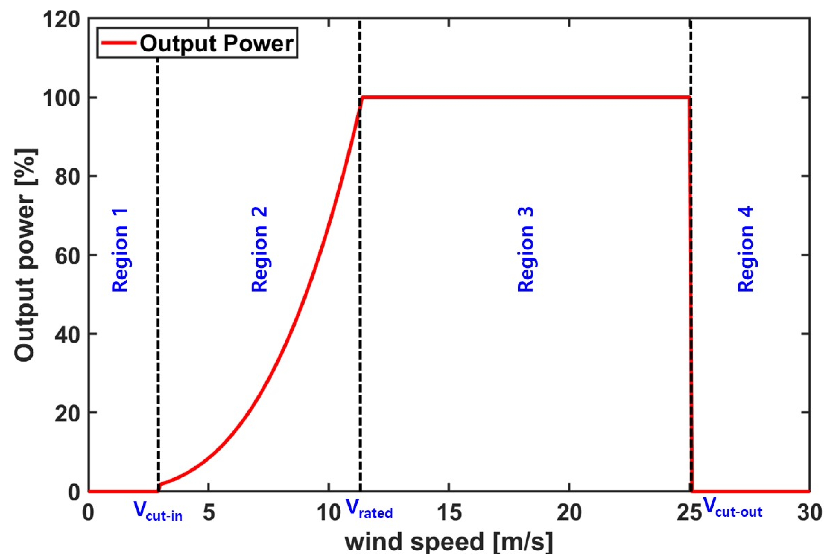
Typically, wind power generation is divided into different operation sections based on the input energy. In region 1 (less than VCut-in), the generator cannot operate due to low input energy; the maximum input energy is extracted based on the wind speed in region 2; in region 3, the output is controlled through pitch control when the wind speed is increased above the rating. Lastly, in region 4, it is difficult to control the output even with pitch control owing to the strong wind speed; thus, the generator is forcibly stopped (VCut-out is exceeded). Figure 1 depicts the output characteristic curve of the wind turbine based on the wind speed.
An offshore wind power generation system is a device that converts the kinetic energy of air into electrical energy. Essentially, the maximum amount of power can be generated only when the efficiency of the wind turbine is maximized, in order to maximize the kinetic energy of the air. Using the input power and mechanical power of air, the output characteristics of the turbine can be expressed as follows:
The input power of air can be calculated using the wind speed and length of the blades as follows [16]:
From Equation (2), the mechanical power of the blade can be defined as follows:
Here, can be calculated according to the tip peripheral speed ratio (λ) and pitch angle (β).
The tip peripheral speed ratio defined in Equation (3) can be calculated as follows:
The mechanical power of the blade can be calculated using the aerodynamic torque () and wind turbine rotation speed () as follows:
Equations (3)–(5) can be used to express the aerodynamic torque of the blade, and the power control value for maximum output control can be calculated as follows [16]:
2.1. Torque Controller
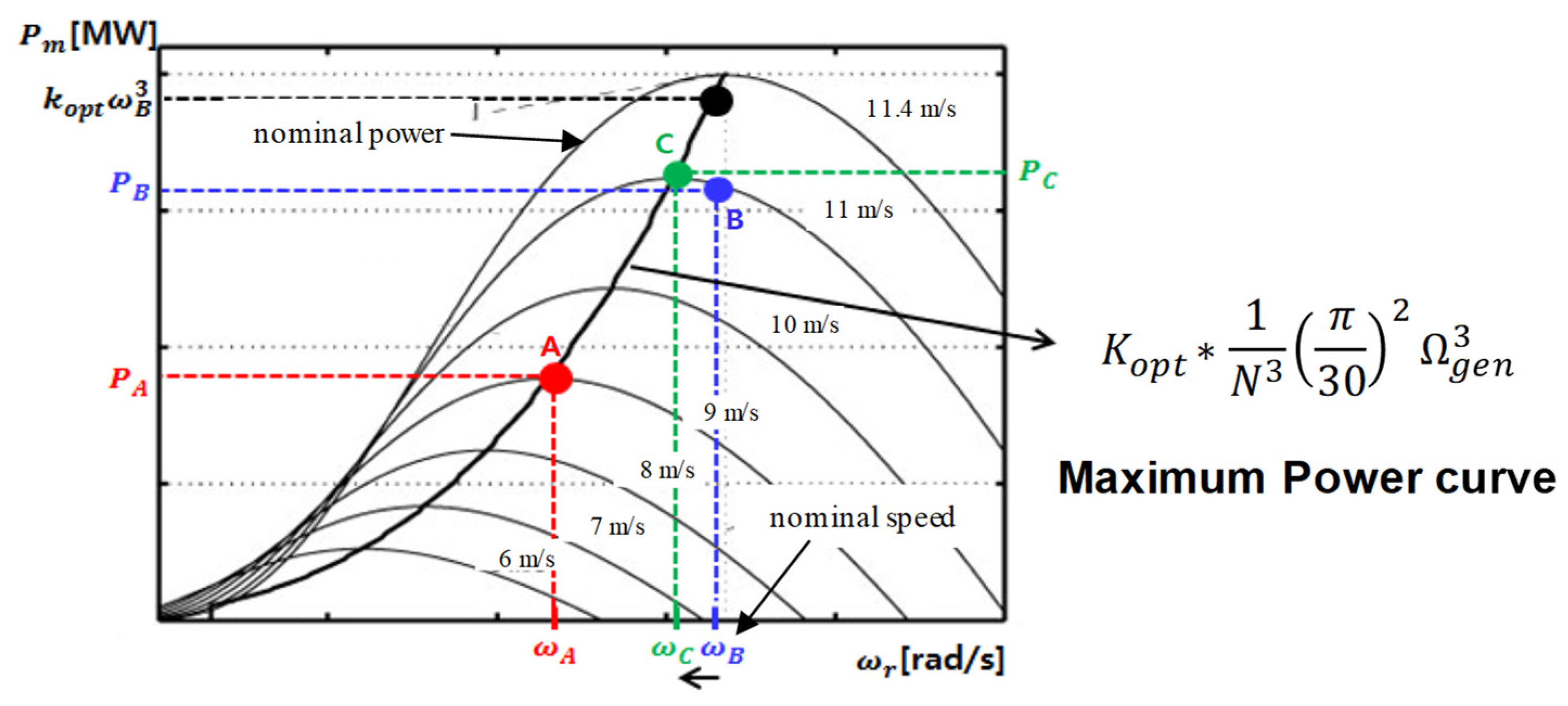
The torque controller is a control strategy used to obtain the maximum amount of power generation based on the rotational speed of the wind turbine in general, which partially corresponds to region 2 explained earlier. The maximum amount of power is obtained by controlling the reference torque to maximize the efficiency () of the turbine corresponding to the rotational speed of the wind turbine. The electrical power control required to adequately satisfy the turbine efficiency can be calculated using the aerodynamic power shown in Equation (6) and by considering that the tip peripheral speed ratio is optimal, as follows:
The constant values presented in Equation (7) are rearranged, the gear ratio of the gearbox is considered, and the generator electrical torque control value is expressed as follows:
The reference torque curve required to obtain the maximum power generation of the generator is depicted in Figure 2.
2.2. Pitch Controller
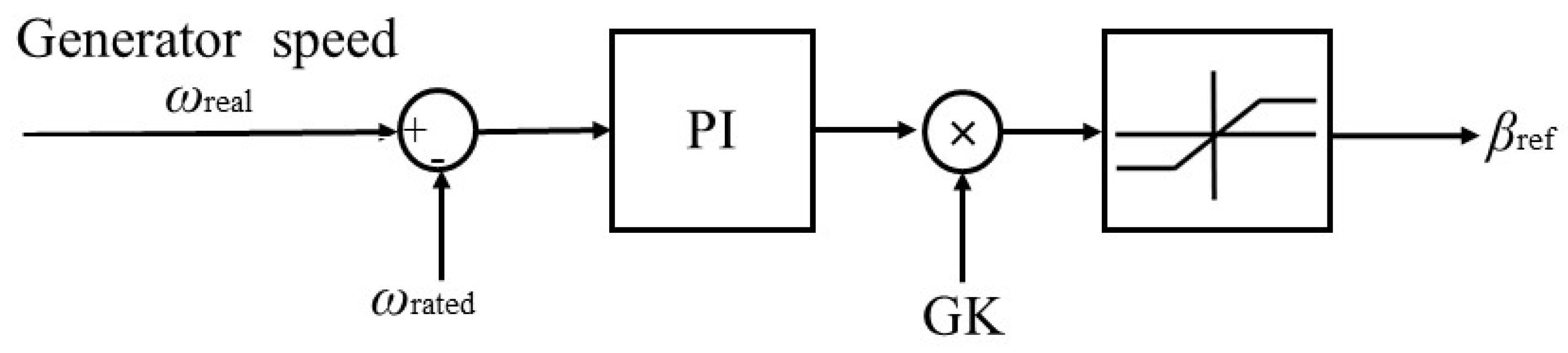
The pitch controller is a control strategy used in region 3 to forcibly reduce the output by reducing the efficiency of the turbine for the equivalent wind speed by adjusting the pitch angle. Essentially, the output of the wind power generator can be maintained at the rated output by varying the pitch angle in the wind above the rated wind speed. The pitch controller generally adjusts the pitch angle using the angular velocity of the generator. A PI controller can be used to adjust the difference between the current generator rotation speed and rated rotation speed. Figure 3 illustrates the control configuration of the pitch controller.
As for the classification of the pitch controller, there is a collective pitch controller (CPC) for controlling all blades at the same time and an individual pitch controller (IPC) for reducing the load on each blade according to the wind shear as the length of the turbine blade increases. In addition, in the case of floating offshore wind turbine systems, since it affects the movement of the floating body according to the control response of the pitch controller, a PI gain considering this is required. Table 1 shows the classification of pitch controllers.
3. Floating Offshore Wind Power System Pitch Controller Design
The lower part of the wind power generator is connected to the floating body in the floating offshore wind power generation system contrary to the onshore–offshore wind power generation system. This implies that the pitch controller of the floating offshore wind power system must be designed by considering the motion characteristics of the platform unlike the pitch controller of the onshore–offshore wind power generation system. Firstly, the design of the existing onshore–offshore wind power system pitch controller considers the dynamic response of only the wind power generator. The PI gain of the existing onshore–offshore wind power system pitch controller can be calculated using Equations (9) and (10) [13,14] as follows:
The pitch controller employs the gain correction coefficient, , which can be calculated as follows:
An external surface vibration of the rotor occurs in the existing onshore–offshore wind power system pitch controller. This vibration phenomenon is transmitted to the tower through the hub, drive train, and yaw bearing of the wind turbine, thereby reducing the lifespan of the wind turbine [17]. Particularly, the blade length increases with the increase in the size of the offshore wind power generation system, and the vibration of the rotor becomes more fatal to the wind turbine. The vibration phenomenon inevitably increases in large wind turbines with relatively long blades because the rotor blades receive different loads based on the altitude owing to the wind shear. An individual pitch control (IPC) is applied to an offshore wind power generation system for land applications to solve this problem.
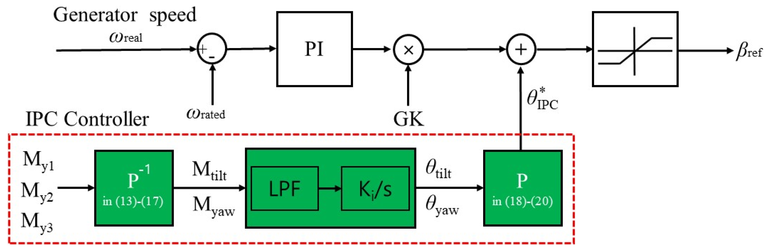
The individual pitch controller increases the wing pitch angle when the rotor blade moves to a higher position than that of the existing land-based pitch controller, and the wing pitch angle decreases when compared to that of the existing land-based pitch controller when the wing moves to a lower position. This can effectively reduce the mechanical load on the rotor blades owing to the wind shear. The individual pitch controller can convert the wing bending moment value measured by the sensor located at the hub, into the fixed coordinate system of the nacelle using the Coleman inverse transformation [18]:
where ψ represents the azimuthal angle.
Using the bending moment values of the fixed coordinate system presented in Equations (13)–(15), Mtilt and Myaw can be calculated as follows:
The angle of the individual pitch controller required to reduce the bending moment (, ) in the rotational coordinate system presented in Equations (16)–(17) can be implemented by using a low-pass filter and an integral controller. The individual pitch angle of each blade, which reduces the fatigue load of the wind turbine due to the vibration of the blade, can be calculated by using the Coleman transformation [9] as follows:
The pitch controller angle calculated by using Equations (9)–(11) and the individual pitch angles calculated in Equations (18)–(20) are combined to generate the final pitch angle for the individual pitch controller. Figure 4 presents a control diagram of the individual pitch control algorithm.
Unlike the existing offshore wind power generation system, the floating offshore wind power generation system interacts with negative damping according to the control response of the pitch controller. This phenomenon is called negative damping, and the floating offshore wind power generation system employs a pitch controller to overcome this problem. A study was conducted on the pitch controller for a floating offshore wind power generation system to solve this problem [14] based on the research results of the negative damping phenomenon caused by the fast response speed of the existing onshore pitch controller [13,14]. The limitations of the land controller can be overcome by reducing the response speed of the pitch controller, thereby reducing the PI gain. The negative damping phenomenon problem can be overcome by reducing the response frequency of the pitch controller when compared to the resonant frequency of the float pitch [14]. A controller is then applied to the floating offshore wind power generation system. Additionally, the research conducted on the existing IPC controller has been primarily focused on the onshore pitch controllers. The performance of an offshore pitch controller applied with an IPC controller is also compared in this study. In summary, in this paper, the performance of CPC and IPC described above was compared. A suitable pitch controller for the floating offshore wind power system was derived by comparing the output characteristics and floating body motion characteristics of the floating offshore wind power generation system according to each controller.
4. Numerical Analysis
4.1. Target Model
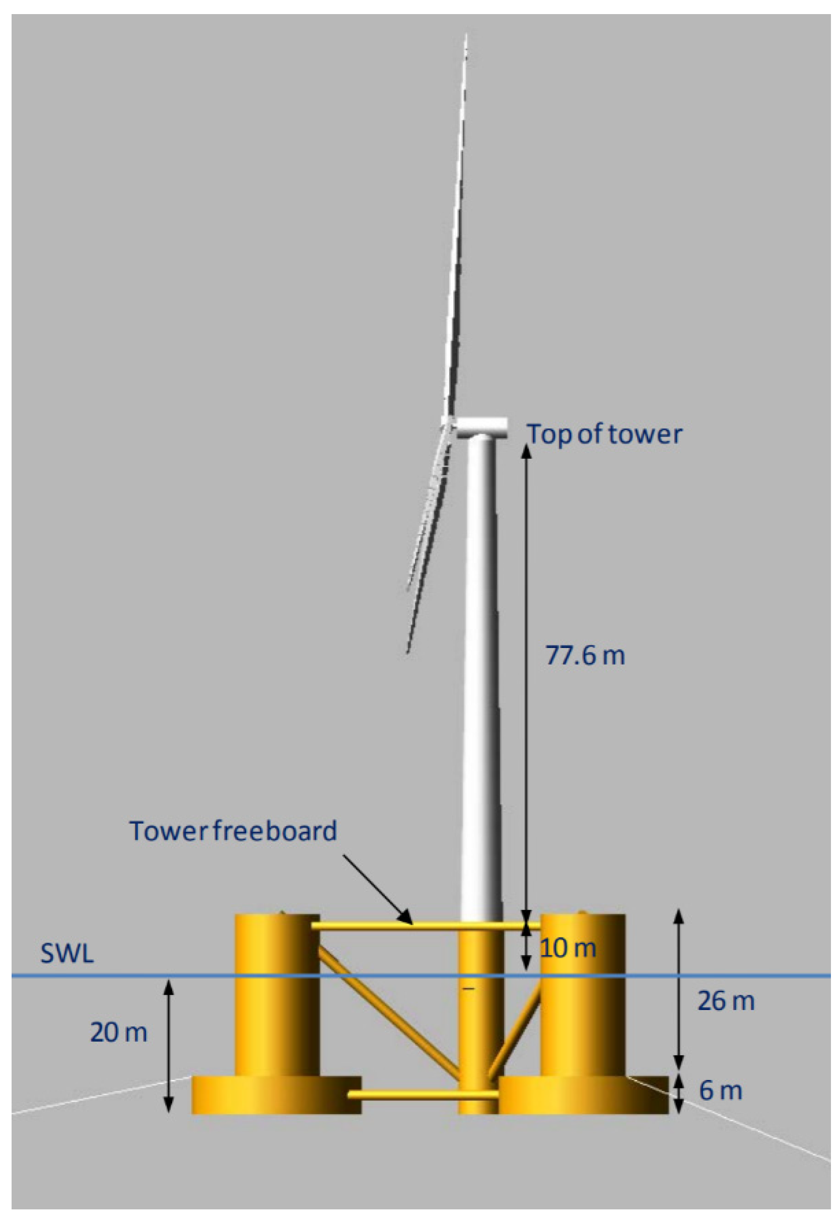
The FAST-v8 model, developed by NREL, is used in this study to analyze the performance of the pitch controller by considering the dynamic characteristics of the floating offshore wind power generation system. MATLAB/Simulink is used to drive the FAST-v8 model, and the numerical analysis is performed by configuring a torque controller and a pitch controller. The NREL 5-MW class floating offshore wind power generation system is used as the wind turbine model for the numerical analysis [14] on an OC4 semi-submersible platform [19]. Figure 5 illustrates the target floating offshore wind power system, Table 2 presents the main specifications of the NREL 5-MW wind turbine used in this study, and Table 3 lists the main specifications of the OC4 semi-submersible platform.
4.2. Analysis Method and Conditions
The analysis of the floating offshore wind turbine is performed by using the 5 MW-class FAST nonlinear wind turbine model implemented in FAST_SFunc.mex for the configuration of FAST using MATLAB/Simulink [20].
Furthermore, a torque controller and pitch controllers are implemented for a floating offshore wind power generation system using MATLAB/Simulink; a pitch controller is implemented for land applications, along with an individual pitch controller and a pitch controller considering negative damping.
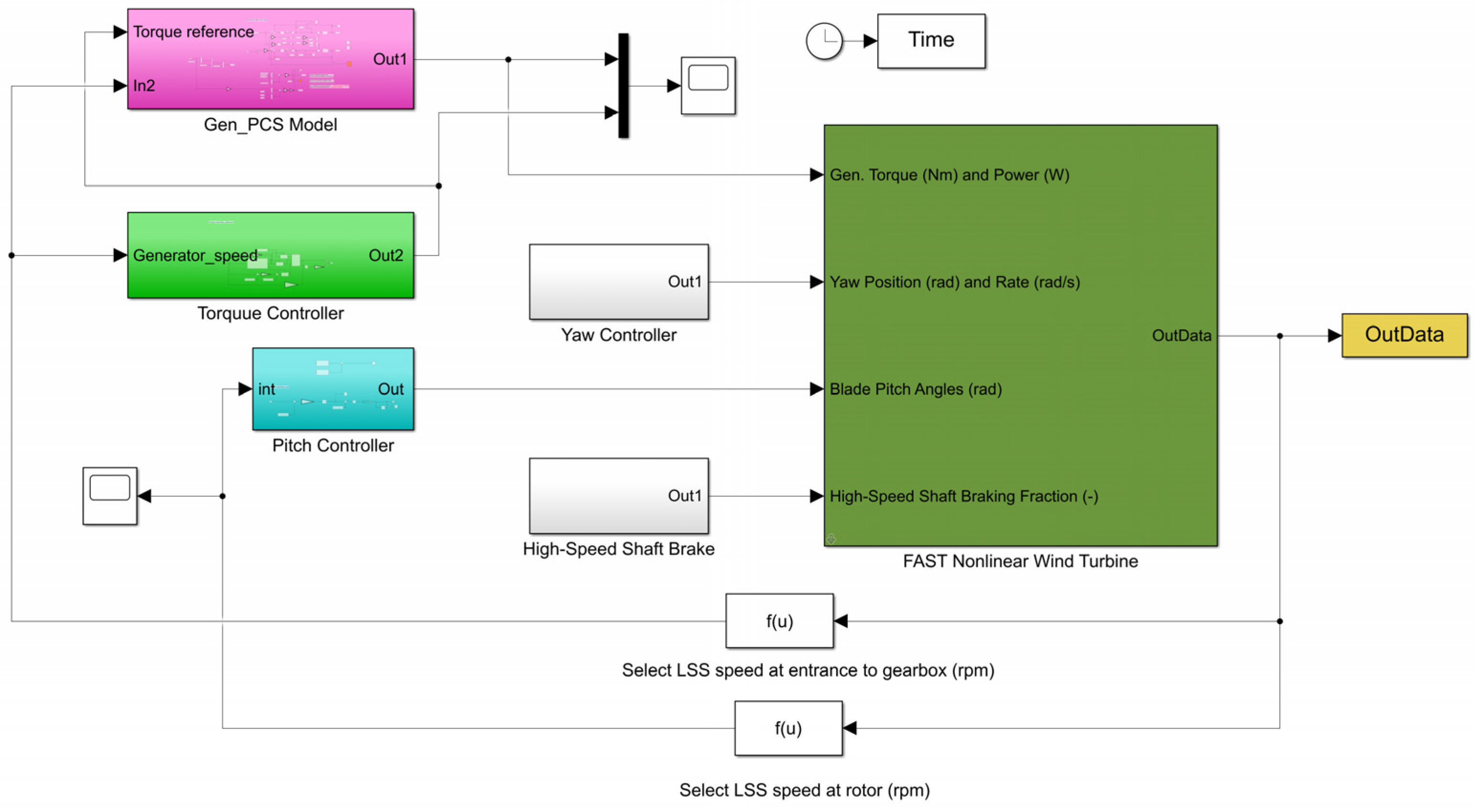
Figure 6 illustrates the MATLAB/Simulink-based FAST configuration used in this study. A rated wind speed of 11.4 m/s is applied as the numerical analysis input wind speed condition, and the Pierson–Moskowitz (PM) spectrum of the significant wave height (Hs = 6 m) and peak wave period(Tp = 10 s) is applied as the input wave condition to verify the floating body motion performance corresponding to the pitch controller. To implement the blue spectrum, the total simulation time was set to 3 h.
5. Results and Discussion
Four pitch controllers are compared in this study. The pitch controllers implemented for both land and offshore applications are composed of a collective pitch controller (CPC) and an individual pitch controller (IPC). The controller characteristics are analyzed by focusing on the platform motion performance of a floating offshore wind power generation system based on the pitch controller.
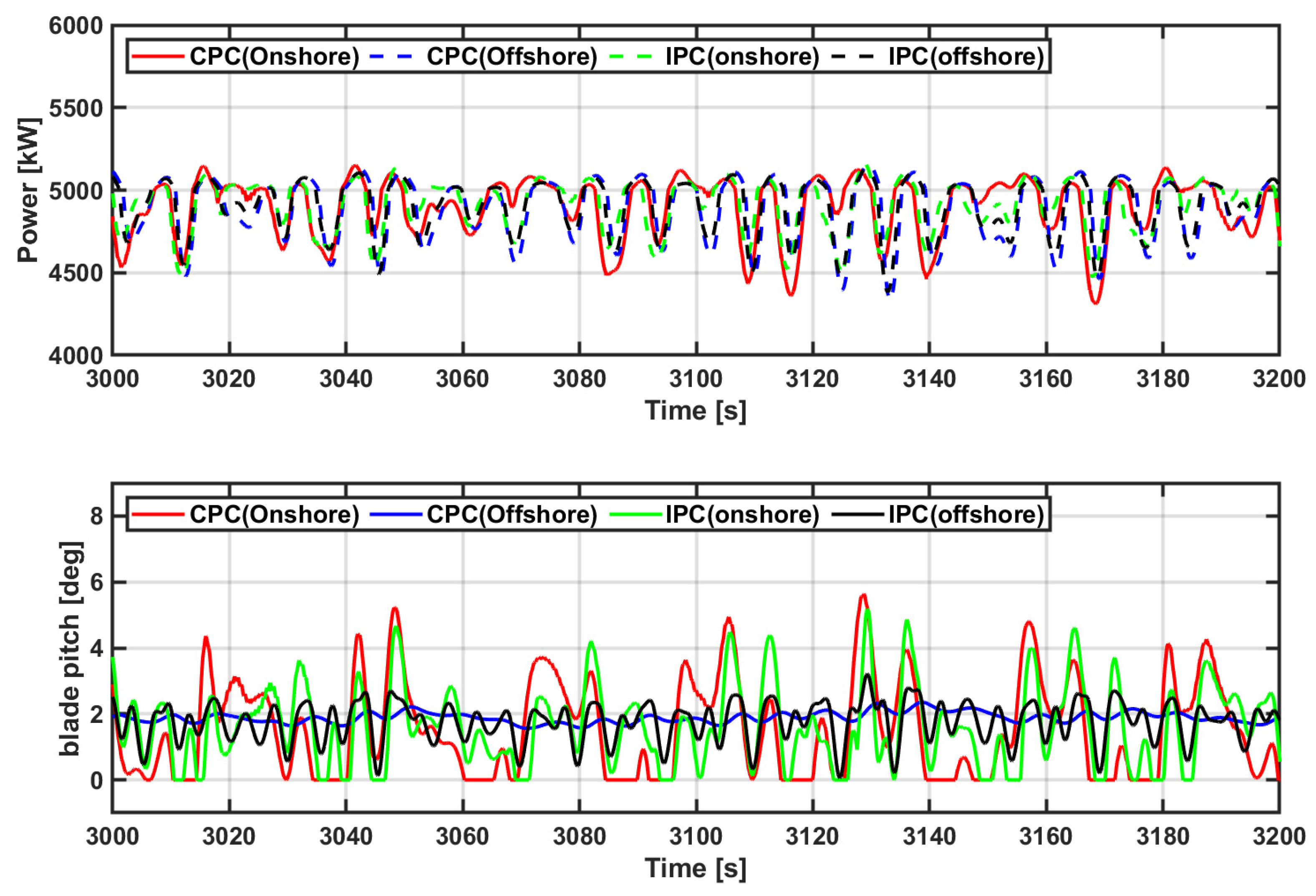
Figure 7 illustrates the output power of the floating offshore wind power generation system based on the pitch controller and the pitch angle of the blades controlled by the pitch controller. The platform motion of CPC for onshore increases and the output power is slightly reduced when compared to that of the CPC for offshore since the CPC for onshore has a high response speed, which can be confirmed through the blade pitch angle. Since the mechanical load of the IPC for onshore is reduced compared to the CPC for onshore, the rated output is maintained relatively well in terms of output. However, it can be seen that the blade pitch angle changes more due to the individual pitch control. The response speed of the pitch controller of the floating offshore wind power system reduces the PI gain of the pitch controller to solve the negative damping problem. This results in a reduced platform motion of CPC for offshore, which can be observed to remain relatively constant at rated power. Specific platform behavior is described later. In addition, if the offshore IPC of the floating offshore wind power generation system is applied, the negative damping phenomenon can be reduced and the mechanical load can also be reduced, so that a constant value is maintained at the rated output. Specific data will be described later.
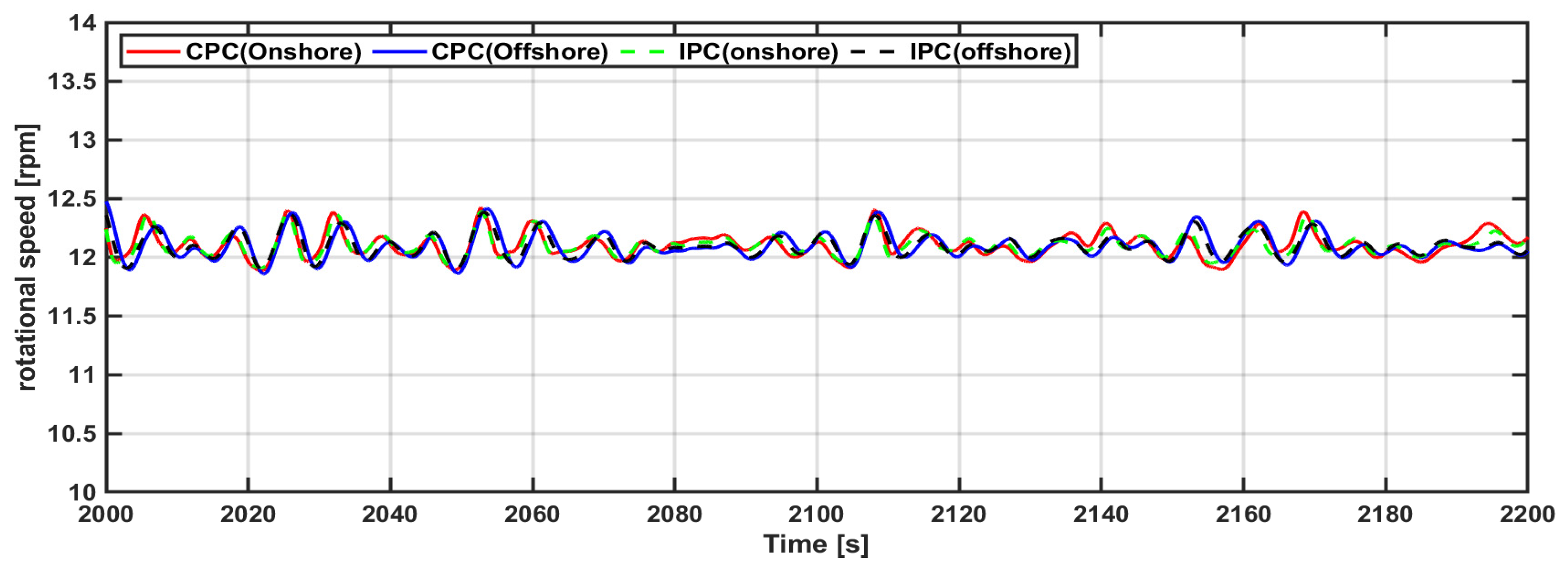
Figure 8 depicts the rotational speed of the rotor of the floating offshore wind power generation system based on the pitch controller. It can be seen from Figure 8 that the rotation speed of the turbine according to each pitch controller is not affected.
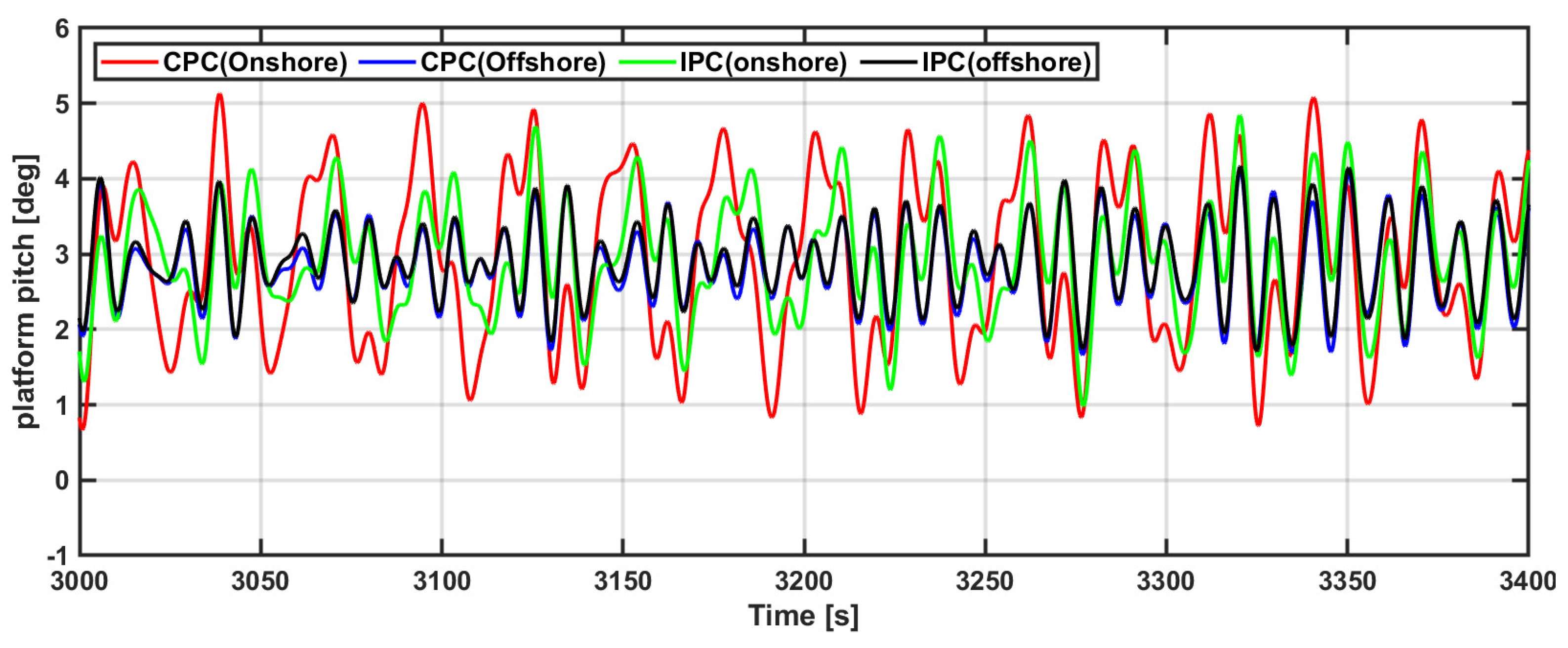
Figure 9 illustrates the follower motion of the floating offshore wind power system platform based on the pitch controller. If the CPC for onshore is applied, it can be seen that the motion of the floating body increases the most. In the case of IPC for onshore, it can be seen that the floating body motion is reduced compared to the CPC for onshore. However, since they are both pitch controllers for onshore, it can be seen that the platform movement is large. For the pitch controller for the floating offshore wind turbine system, it can be seen that the floating body motion is greatly reduced in the offshore CPC considering the movement of the platform. In addition, the floating body motion of IPC for offshore was relatively reduced compared to the marine CPC. This can be confirmed through the detailed data below.
The platform follow-up motion of the floating offshore wind power system must be controlled within an average of five degrees with the maximum difference lying within 10 degrees [21]. Essentially, the pitch controller of the floating offshore wind power generation system must be designed to reduce the platform motion according to above guide line.
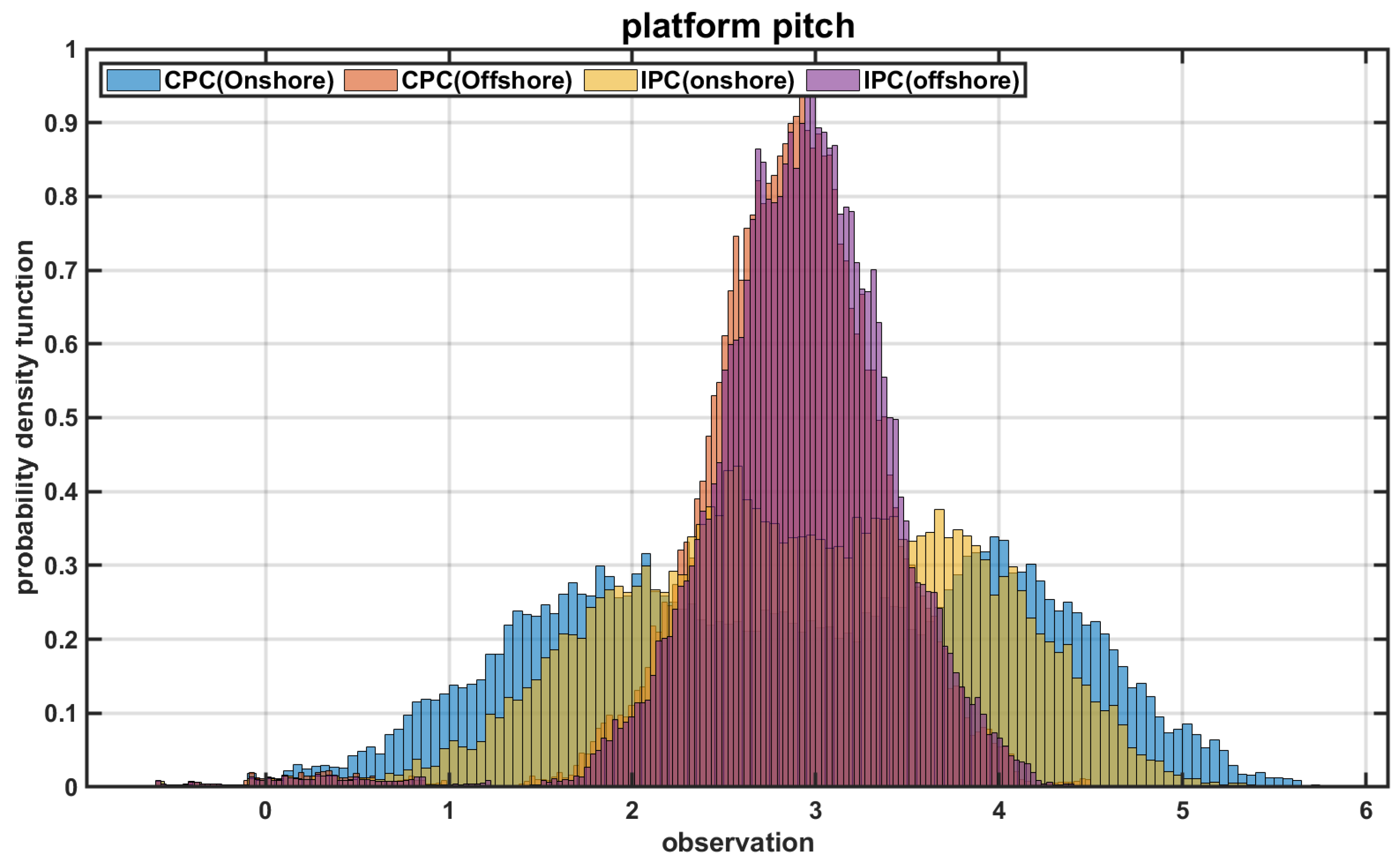
Figure 10 illustrates the histogram of the platform response of the floating offshore wind power system based on the pitch controller. CPC for onshore shows the largest standard deviation in terms of platform motion. IPC for onshore shows a smaller standard deviation than CPC for onshore, but because it is a pitch controller for onshore, it shows a relatively large platform motion. Both CPC and IPC for offshore show relatively smaller standard deviation than pitch controllers for onshore. Among them, the IPC for offshore shows the least platform movement because the mechanical load is reduced. In conclusion, it can be confirmed that the pitch controller which considers negative damping is suitable because the pitch controller for the floating offshore wind power system must consider the platform motion differently from the existing controllers. Additionally, it can be confirmed that the platform movement remains unaffected even if an individual pitch controller is applied.
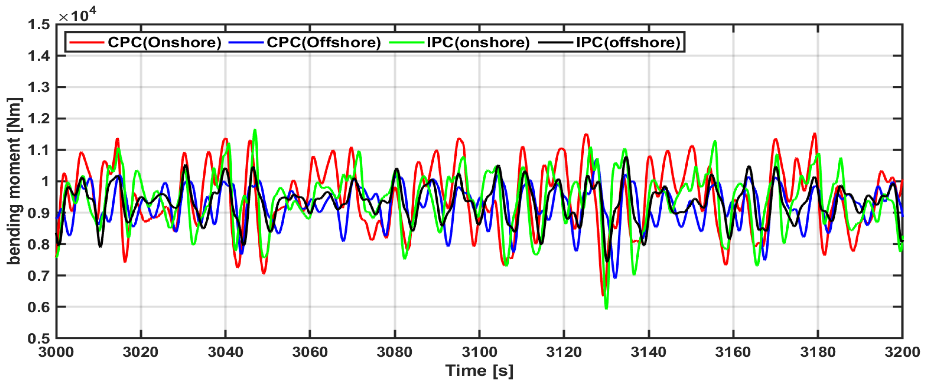
Figure 11 presents the blade bending moment of the floating offshore wind power system based on the pitch controller. For onshore or offshore applications, IPC exhibits lower mechanical load variability than CPC. However, offshore controllers show lower mechanical load variability than onshore controllers. Specific data can be seen in the figure below.
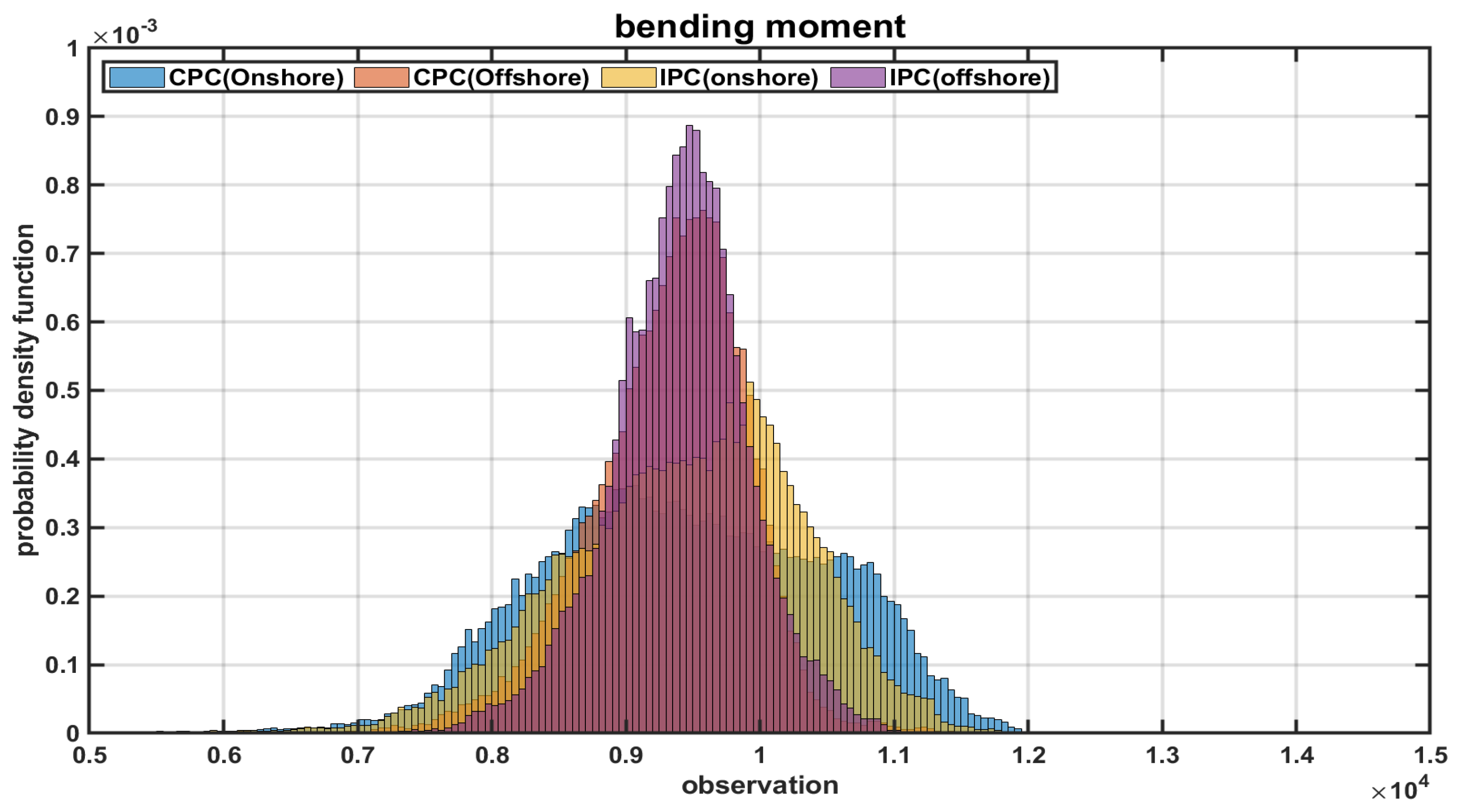
Figure 12 presents the histogram of the bending moment of the floating offshore wind turbine system based on each pitch controller. As described above, offshore pitch controllers showed lower variability in terms of mechanical load than onshore pitch controllers, and among them, offshore IPC showed the lowest mechanical load variability.
Table 4 summarizes the important points of this paper. From Table 4, it can be confirmed that the most suitable pitch controller for a floating offshore wind turbine system is an offshore IPC. This can be seen in terms of output power generation and platform motion.
Table 5 presents the output-limiting performance of each pitch controller at an input wind speed of 18 m/s. The negative damping phenomenon is reduced with the increase in the input wind speed, and the output-limiting performance of each pitch controller is almost identical (within 1%). Table 6 shows a summary of terms used in this paper.
6. Conclusions
In the floating offshore wind turbine system, the power generation performance and the floating body movement are changed according to each pitch controller. Therefore, this paper analyzed the platform motion characteristics and power generation performance of floating offshore wind turbine system based on each pitch controller performance. Since both CPC and IPC for onshore are not pitch controllers reflecting the characteristics of floating bodies, it was confirmed that the motion of the floating body increased and the power generation output decreased. However, both CPC and IPC for offshore have eliminated the negative damping phenomenon due to the PI gain setting considering the resonant frequency of the floating body, and this improved the performance of the floating body’s motion and power generation output compared to the onshore pitch controllers. Among them, IPC for offshore showed the best performance by reducing mechanical load as well. Offshore IPC increased 0.42% in average output power and reduced 19.3% in output power variability. Additionally, the volatility of the platform movement was greatly reduced to about 64.5%. In conclusion, it was confirmed that the most suitable pitch controller for the floating offshore wind turbine system is the offshore IPC.
Author Contributions
K.-H.K. managed the project; C.R. performed the numerical simulation and analysis; C.R. drafted the paper; K.-H.K. and Y.-J.H. edited the paper; C.R. and H.-J.A. contributed to this study; C.R. and H.-J.A. have read and agreed to the published version of the manuscript. All authors have read and agreed to the published version of the manuscript.
Funding
This research received no external funding.
Institutional Review Board Statement
Not applicable.
Informed Consent Statement
Not applicable.
Data Availability Statement
Not applicable.
Acknowledgments
This research was supported by a grant from National R&D Project “Development of Predictive Maintenance Technology for Floating Offshore Wind Power Systems Based on Digital Twin Technology (PNS3910)” funded by the Ministry of Trade, Industry and Energy (MOTIE) and the Korea Energy Technology Evaluation and Planning (KETEP).
Conflicts of Interest
The authors declare no conflict of interest.
References
- Taveira-Pinto, F.F.; Iglesias, G.; Rosa-Santos, P.; Deng, Z.D. Preface to Special Topic: Marine Renewable Energy. J. Renew. Sustain. Energy 2015, 7, 061601. [Google Scholar] [CrossRef] [Green Version]
- Esteban, M.D.; Diez, J.J.; López, J.S.; Negro, V. Why Offshore Wind Energy? Renew. Energy 2011, 36, 444–450. [Google Scholar] [CrossRef] [Green Version]
- Esteban, M.D.; López-Gutiérrez, J.S.; Negro, V.; Matutano, C.; García-Flores, F.M.; Millán, M.Á. Offshore Wind Foundation Design: Some Key Issues. J. Environ. Eng. 2014, 137, 1–6. [Google Scholar]
- Pacheco, A.; Gorbeña, E.; Sequeira, C.; Jerez, S. An Evaluation of Offshore Wind Power Production by Floatable Systems: A Case Study From SW Portugal. Energy 2017, 131, 239–250. [Google Scholar] [CrossRef]
- Kim, H.C.; Kim, M.H.; Lee, J.Y.; Kim, E.S.; Zhang, Z. Global Performance Analysis of 5 MW WindFloat and OC4 Semi-Submersible Floating Offshore Wind Turbines (FOWT) by Numerical Simulations. In Proceedings of the 27th International Ocean and Polar Engineering Conference, San Francisco, CA, USA, 25–30 June 2017; pp. 25–30. [Google Scholar]
- Merabet, A.; Thongam, J.; Gu, J. Torque and pitch angle control for variable speed wind turbines in all operating regimes. In Proceedings of the 2011 10th International Conference on Environment and Electrical Engineering, Rome, Italy, 8–11 May 2011; pp. 1–5. [Google Scholar]
- Senjyu, T.; Sakamoto, R.; Urasaki, N.; Funabashi, T.; Fujita, H.; Sekine, H. Output Power Leveling of Wind Turbine Generator for All Operating Regions by Pitch Angle Control. IEEE Trans. Energy Convers. 2006, 21, 467–475. [Google Scholar] [CrossRef]
- Cheon, J.; Kwon, S.; Choi, Y. Design of a Pitch Controller Using Disturbance Accommodating Control for Wind Turbines Under Stochastic Environments. In Proceedings of the 2014 IEEE 23rd International Symposium on Industrial Electronics, Istanbul, Turkey, 1–4 June 2014; pp. 2572–2577. [Google Scholar]
- Jing, Y.; Sun, H.; Zhang, L.; Zhang, T. Variable Speed Control of Wind Turbines Based on the quasi-Continuous High-Order Sliding Mode Method. Energies 2017, 10, 1626. [Google Scholar] [CrossRef] [Green Version]
- He, K.; Qi, L.; Zheng, L.; Chen, Y. Combined Pitch and Trailing Edge Flap Control for Load Mitigation of Wind Turbines. Energies 2018, 11, 2519. [Google Scholar] [CrossRef] [Green Version]
- Corcuera, A.D.D.; Pujana-Arrese, A.; Ezquerra, J.M.; Segurola, E.; Landaluze, J.H. Based Control for Load Mitigation in Wind Turbines. Energies 2012, 5, 938–967. [Google Scholar] [CrossRef] [Green Version]
- Selvam, K. Rept. ECN-E-07-053; Individual Pitch Control for Large Scale Wind Turbines-Multivariable Control Approach. Energy Research Centre of The Netherlands: Petten, The Netherlands, 2007.
- Larsen, T.J.; Hanson, T.D. A Method to Avoid Negative Damped Low Frequent Tower Vibrations for a Floating, Pitch Controlled Wind Turbine. J. Phys. Conf. Ser. 2007, 75, 012073. [Google Scholar] [CrossRef]
- Jonkman, J.; Butterfield, S.; Musial, W.; Scott, G. Definition of a 5-MW Reference Wind Turbine for Offshore System Development; Technical Report No. NREL/TP-500-38060; National Renewable Energy Lab. (NREL): Golden, CO, USA, 2009.
- Jonkman, J. Definition of the Floating System for Phase IV of OC3; Technical Report No. NREL/TP-500-47535; National Renewable Energy Lab. (NREL): Golden, CO, USA, 2010.
- Hau, E. Wind Turbines: Fundamentals, Technologies, Application, Economics; Springer Science & Business Media: Berlin/Heidelberg, Germany, 2013. [Google Scholar]
- Wright, A.D. Modern Control Design for Flexible Wind Turbines; Technical Report No. NREL/TP-500-35816; National Renewable Energy Laboratory: Golden, CO, USA, 2004.
- Van Engelen, T.; Van der Hooft, E. Individual Pitch Control Inventory; Technical Report No. ECN-C-03-138; Technical University of Delft: Delft, The Netherlands, 2005. [Google Scholar]
- Robertson, A.; Jonkman, J.; Masciola, M.; Song, H.; Goupee, A.; Coulling, A.; Luan, C. Definition of the Semisubmersible Floating System for Phase II of OC4; Technical Report No. NREL/TP-5000-60601; National Renewable Energy Lab. (NREL): Golden, CO, USA, 2014.
- Singh, M.; Muljadi, E.; Jonkman, J.; Gevorgian, V.; Girsang, I.; Dhupia, J. Simulation for Wind Turbine Generators-with FAST and MATLAB-Simulink Modules; Technical Report No. NREL/TP-5D00-59195; National Renewable Energy Lab. (NREL): Golden, CO, USA, 2014.
- Ramachandran, G.K.V.; Vita, L.; Krieger, A.; Mueller, K. Design Basis for the Feasibility Evaluation of Four Different Floater Designs. Energy Procedia 2017, 137, 186–195. [Google Scholar] [CrossRef]
Figure 1.
Wind turbine output characteristic curve based on wind speed.

Figure 2.
Reference torque curve corresponding to change in generator angular velocity.

Figure 3.
Pitch controller configuration diagram for rated output control.

Figure 4.
IPC pitch control algorithm configuration diagram.

Figure 5.
Floating wind system design with OC4 semi-submersible platform [19].
Figure 5.
Floating wind system design with OC4 semi-submersible platform [19].

Figure 6.
Matlab/Simulink based FAST configuration.

Figure 7.
Output characteristics and blade pitch angle of floating offshore wind turbine based on pitch controller.
Figure 7.
Output characteristics and blade pitch angle of floating offshore wind turbine based on pitch controller.

Figure 8.
Rotor rotation speed of floating offshore wind turbine based on pitch controller.

Figure 9.
Platform pitch movement of floating offshore wind turbine based on pitch controller.

Figure 10.
Histogram of platform pitch motion of floating offshore wind turbine based on pitch controller.
Figure 10.
Histogram of platform pitch motion of floating offshore wind turbine based on pitch controller.

Figure 11.
Blade bending moment of floating offshore wind turbine based on pitch controller.

Figure 12.
Histogram of blade bending moment of floating wind turbine based on pitch controller.


Table 1.
Classification to pitch controller of floating wind power generation system.
| Classification | Target |
|---|---|
| Collective Pitch Controller | Onshore |
| Collective Pitch Controller | Offshore |
| Individual Pitch Controller | Onshore |
| Individual Pitch Controller | Offshore |
Table 2.
Properties selected for the NREL 5-MW baseline wind turbine (source from: [14]).
Table 2.
Properties selected for the NREL 5-MW baseline wind turbine (source from: [14]).
| Rating | 5 MW |
|---|---|
| Rotor Orientation, Configuration | Upwind, 3 Blades |
| Drivetrain | High Speed, Multiple-Stage Gearbox |
| Rotor, Hub Diameter | 126 m, 3 m |
| Hub Height | 90 m |
| Cut-In, Rated, Cut-Out Wind Speed | 3 m/s, 11.4 m/s, 25 m/s |
| Cut-In, Rated Rotor Speed | 6.9 rpm, 12.1 rpm |
| Rated Tip Speed | 80 m/s |
| Rotor Mass | 1.1 × 10⁵ kg |
| Nacelle Mass | 2.4 × 10⁵ kg |
| Tower Mass | 3.4746 × 10⁵ kg |
Table 3.
Floating platform structural (OC4 semi-submersible) properties (source from: [19]).
Table 3.
Floating platform structural (OC4 semi-submersible) properties (source from: [19]).
| Platform Mass Including Ballast | 1.3473 × 10⁷ kg |
|---|---|
| CM Location Below SWL | 13.46 m |
| Platform Roll Inertia About CM | 6.827 × 10⁹ kg-m2 |
| Platform Pitch Inertia About CM | 6.827 × 10⁹ kg-m2 |
| Platform Yaw Inertia About CM | 1.226 × 10¹⁰ kg-m2 |
| Depth of Platform Base Below SWL (Total Draft) | 20 m |
| Elevation of Main Column (Tower Base) above SWL | 10 m |
| Elevation of Offset Columns Above SWL | 12 m |
| Length of Upper Columns | 26 m |
| Length of Base Columns | 6 m |
| Depth to Top of Base Columns Below SWL | 14 m |
Table 4.
Average value and standard deviation of output data based on pitch controller in 11.4 m/s.
| Wind Speed [m/s] | CPC | IPC | ||||||
|---|---|---|---|---|---|---|---|---|
| 11.4 (Rated Speed) | Onshore | Offshore | Onshore | Offshore | ||||
| Value | Value | Diff. [%] | Value | Diff. [%] | Value | Diff. [%] | ||
| Power [kW] | Avg | 4897.93 | 4904.77 | 0.14 | 4908.72 | 0.22 | 4918.74 | 0.42 |
| S. D | 187.05 | 172.6 | ̶ 7.73 | 168.28 | −10.04 | 150.96 | −19.30 | |
| Rot-Speed [RPM] | Avg | 12.1 | 12.1 | 0 | 12.1 | 0 | 12.1 | 0 |
| S. D | 0.12 | 0.11 | ̶ 8.26 | 0.11 | −8.26 | 0.09 | −21.86 | |
| Platform Pitch [deg] | Avg | 2.93 | 2.89 | ̶ 1.27 | 2.96 | 1.01 | 2.90 | −0.97 |
| S. D | 1.21 | 0.44 | −63.35 | 0.92 | −24.34 | 0.43 | −64.50 | |
| Bending Moment [Nm] | Avg | 9437.49 | 9321.27 | −1.23 | 9435.35 | −0.02 | 9318.75 | −1.26 |
| S. D | 1033.75 | 559.24 | −45.9 | 871.33 | −15.71 | 504.92 | −51.16 | |
Table 5.
Average value and standard deviation of output data based on pitch controller in 18 m/s.
| Wind Speed [m/s] | CPC | IPC | ||||||
|---|---|---|---|---|---|---|---|---|
| 18 | Onshore | Offshore | Onshore | Offshore | ||||
| Value | Value | Diff. [%] | Value | Diff. [%] | Value | Diff. [%] | ||
| Power [kW] | Avg | 4968.87 | 4959.69 | −0.18 | 4968.54 | −0.01 | 4962.66 | −0.12 |
| S. D | 69.57 | 70.12 | 0.79 | 69.91 | 0.49 | 69.02 | −0.79 | |
Table 6.
Common abbreviations that do not need defining in the text.
| Abbreviation | Meaning |
|---|---|
| Rotor Power (Mechanical Power) | |
| Input Power (Wind Power) | |
| Turbine Coefficient | |
| Length of Rotor Blades | |
| Density of Air | |
| Wind Speed | |
| Rotational Speed of Rotor | |
| Mechanical Torque | |
| Tip Speed Ratio | |
| N | Gear Ratio |
| Drivetrain Inertia | |
| Rated Low-Speed Shaft Rotational Speed | |
| Natural Frequency of PI Controller | |
| Damping Ratio of PI Controller | |
| Rotor-Collective Blade-Pitch Angle | |
| Blade-Pitch Angle Which Sensitivity Has Doubled | |
| Gain-Correction Factor |
Publisher’s Note: MDPI stays neutral with regard to jurisdictional claims in published maps and institutional affiliations. |
© 2022 by the authors. Licensee MDPI, Basel, Switzerland. This article is an open access article distributed under the terms and conditions of the Creative Commons Attribution (CC BY) license (https://creativecommons.org/licenses/by/4.0/).
Share and Cite
MDPI and ACS Style
Roh, C.; Ha, Y.-J.; Ahn, H.-J.; Kim, K.-H. A Comparative Analysis of the Characteristics of Platform Motion of a Floating Offshore Wind Turbine Based on Pitch Controllers. Energies 2022, 15, 716. https://doi.org/10.3390/en15030716
AMA Style
Roh C, Ha Y-J, Ahn H-J, Kim K-H. A Comparative Analysis of the Characteristics of Platform Motion of a Floating Offshore Wind Turbine Based on Pitch Controllers. Energies. 2022; 15(3):716. https://doi.org/10.3390/en15030716
Chicago/Turabian StyleRoh, Chan, Yoon-Jin Ha, Hyeon-Jeong Ahn, and Kyong-Hwan Kim. 2022. "A Comparative Analysis of the Characteristics of Platform Motion of a Floating Offshore Wind Turbine Based on Pitch Controllers" Energies 15, no. 3: 716. https://doi.org/10.3390/en15030716
Note that from the first issue of 2016, this journal uses article numbers instead of page numbers. See further details here.