1. Introduction
Lithium-ion batteries (LIB) are widely used as power sources for various products, from portable electronic devices to electric vehicles due to their high capacity, high power, and low self-discharge rate [
1,
2,
3]. However, there have been many reports of fire and explosion accidents due to thermal runaway of LIB, which raises concerns about the safety of electric vehicles [
4]. One of the main causes of thermal runaway of LIB for electric vehicle is mechanical abuse [
4,
5,
6,
7]. Since the LIB of electric vehicles is exposed to various mechanical loads such as vibration, shock, and collision, the separator of LIB can fail. The failure of the separator is an important problem leading to an internal short circuit and thermal runaway of LIB. In order to prevent thermal runaway of LIB, studies to predict the internal short circuit of the LIB under a mechanical load and to analyze the thermal runaway mechanism are being actively conducted [
8,
9].
Hu et al. proposed an ISC diagnostic method integrating a multi-state-fusion ISC resistance estimator and a recursive total least squares method with a variant-forgetting-based bias compensator. The proposed method accurately predicted the ISC in real time even under battery deterioration and disturbance conditions. However, the mechanical, electrical, and thermal responses of LIB cell were not analyzed [
10]. Wu et al. calculated the SoC (state of charge) and temperature of the LIB cell using a 1D electro-thermal coupled model. However, the LIB cell was modeled simply in 1D, and there was a limitation to analyzing the response of the LIB cell to a mechanical load [
11]. Sahraei et al. conducted a study on the mechanical response of a small pouch cell under various mechanical loading conditions such as compression, tension, and bending through experiments [
12]. They developed a finite element model by applying material property curves measured through experiments. In addition, the experimental method showed that the reaction force drop, voltage drop, and temperature rise occurred at the same time that the internal short circuit of the LIB cell occurred. Subsequently, Sahraei and Wierzbicki proposed an analytical procedure to extract the homogenized properties of cylindrical cells [
13,
14]. The proposed method predicted the experimental results accurately. In addition, Sahraei et al. developed a micro-RVE (representative volume element) model to study the micro-scale failure mechanism for complex loads of more than two axes of LIB cells [
15]. Breitfuss et al. developed a detailed layer model for LiMn
2O
4/graphite pouch cells and compared them with experimental results for three-point bending, in-plane compression, and cylindrical rod impact tests [
16]. The developed detailed layer model showed a peak of reaction force similar to the experimental value, but showed a difference in the deformation pattern, and did not successfully predict the load-displacement curve. Zhou, W. developed a model that considers material property changes in the lithiation/delithiation process. Using the developed model, the stress gradient of the lithium-ion battery with the external mechanical load was analyzed in consideration of lithium-ion diffusion. However, only the mechanical response to the elastic region was analyzed, and the electrical and thermal responses were not analyzed [
17]. Lai et al. developed an RVE model and a kinematic model of a pouch-type LIB cell and calculated the mechanical response to in-plane and out-of-plane quasi-static compressive loads [
18]. Based on the experimental results, they constructed a finite element model by modeling the cathode and anode with foam material and performed a buckling analysis including kink and shear bands. The constructed model accurately predicted the buckling pattern of the mechanical experiment, and the stress and strain were also consistent with the experimental values. The LIB mechanical model developed in this study can predict the starting point of the internal short circuit of the LIB at the mechanical level by analyzing the stress, strain, and peak of reaction force, but there is a limit in analyzing the exothermic characteristics of LIB leading to thermal runaway.
Zhang et al. developed an RS (representative sandwich) model consisting of five representative layers of a LIB cell composed of about 165 layers to analyze the exothermic characteristics and starting point of the internal short circuit in the LIB cell, and mechanical-electrical-thermal coupled analysis was performed [
8,
9]. The RS model can predict the starting point of the internal short circuit based on the equivalent plastic strain of the separator only for the hemispherical indenter indentation test. The temperature rise, current density distribution, and voltage drop of the LIB were reasonably predicted after the internal short circuit. However, in practice, the LIB is exposed to various mechanical loads. Therefore, it is necessary to study the effect of the internal short circuit area with the various indenters on the mechanical, electrical, and thermal properties of the LIB.
In this paper, the starting point of internal short circuit in LIB cell is predicted using a two-way mechanical-electrical-thermal coupled analysis method. In addition, the mechanical response of the LIB cell such as in the internal short circuit area for various indenters was analyzed, and the effects of the internal short circuit area on the electrical, and thermal response of the LIB cell were analyzed with various indenters: cylindrical, hemispherical, and conical. The mechanical response was calculated considering the material nonlinearity, including hardening. The electrical response with the internal short circuit was calculated using Maxwell’s equation. The thermal response with the internal short circuit was calculated using the 3D heat conduction equation. In comparison with the indentation test, the analysis model accurately predicted the starting point of the internal short circuit under the mechanical indentation condition. The starting point of internal short circuit and the size of the internal short circuit area is in the following order: cylindrical, hemispherical, conical. It was found that the voltage drop, current, Joule heat and maximum temperature of the LIB cell were large in the order of cylindrical, hemispherical, and conical indenters within the large internal short circuit area.
2. Mechanical-Electrical-Thermal Coupled Analysis for Predicting Internal Short Circuit
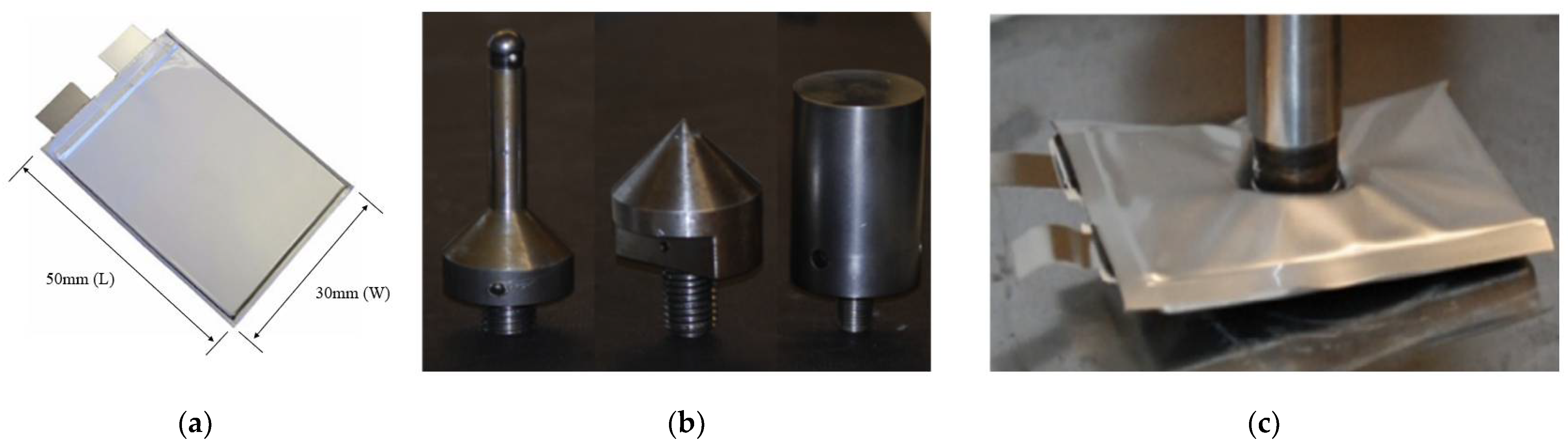
Figure 1a shows the pouch type LIB cell, the subject of this study,
Figure 1b shows the hemispherical, conical, and cylindrical indenter [
19], and
Figure 1c shows the indentation test of the pouch type LIB cell [
12]. The LIB cell used in this study is 30 mm (W) × 50 mm (L) × 4.6 mm (H) and is a small LiCoO2 pouch cell with a nominal voltage of 3.7 V and a nominal capacity of 740 mAh. The three indenters used for indentation were a cylindrical indenter with a diameter of 6.35 mm, a hemispherical indenter with a diameter of 12.7 mm, and a 120° conical indenter. In the indentation test, the center of the pouch type LIB cell is compressed, as shown in
Figure 1c, and reaction force, voltage, and temperature are measured during the test. In this study, to simulate the indentation test performed only experimentally, a two-way mechanical-electrical-thermal coupled analysis technique was developed, which simultaneously calculates the mechanical, electrical, and thermal responses.
2.1. Mechanical-Electrical-Thermal Coupled Analysis Using Finite Element Method
As the mechanical response, the failure of the separator due to the indentation load is calculated considering material nonlinearity, and the thermal expansion with the temperature change is calculated, and it is shown in Equations (1)–(5).
where
is the time independent mass matrix,
is the linear strain incremental stiffness matrix,
is the nonlinear strain incremental stiffness matrix,
is the linear strain displacement transformation matrix,
is the non-linear strain displacement transformation matrix,
is the incremental stress–strain material property matrix,
is the volume,
is the stress matrix,
is the total strain,
is the thermal strain,
is the thermal expansion coefficient,
is the acceleration vector,
is the displacement vector,
is the external load vector, and
is the time.
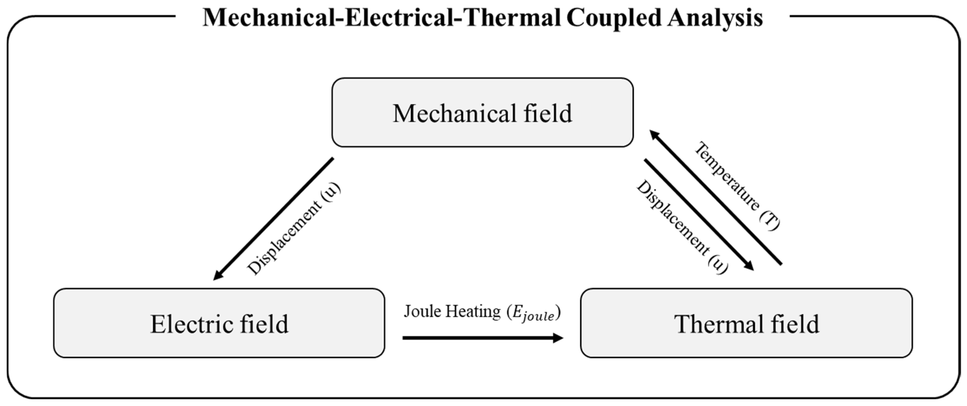
The electric response is calculated using the modified Maxwell’s equation ignoring the decrease in electromagnetic force. Electric field strength, voltage, current, and Joule heat are calculated as shown in Equations (6)–(8).
where
is the del operator,
is the current density vector,
is the electrical conductivity matrix,
is the electric field strength vector,
is the voltage,
is the joule heat.
As the thermal response, the heat transferred by heat conduction and the temperature change due to the heat source are calculated, and it is shown in Equation (9).
is the density,
is the specific heat,
is the temperature,
is the time,
is the del operator,
is the thermal conductivity, and
is the heat generation rate. Please refer to the
Figure 2.
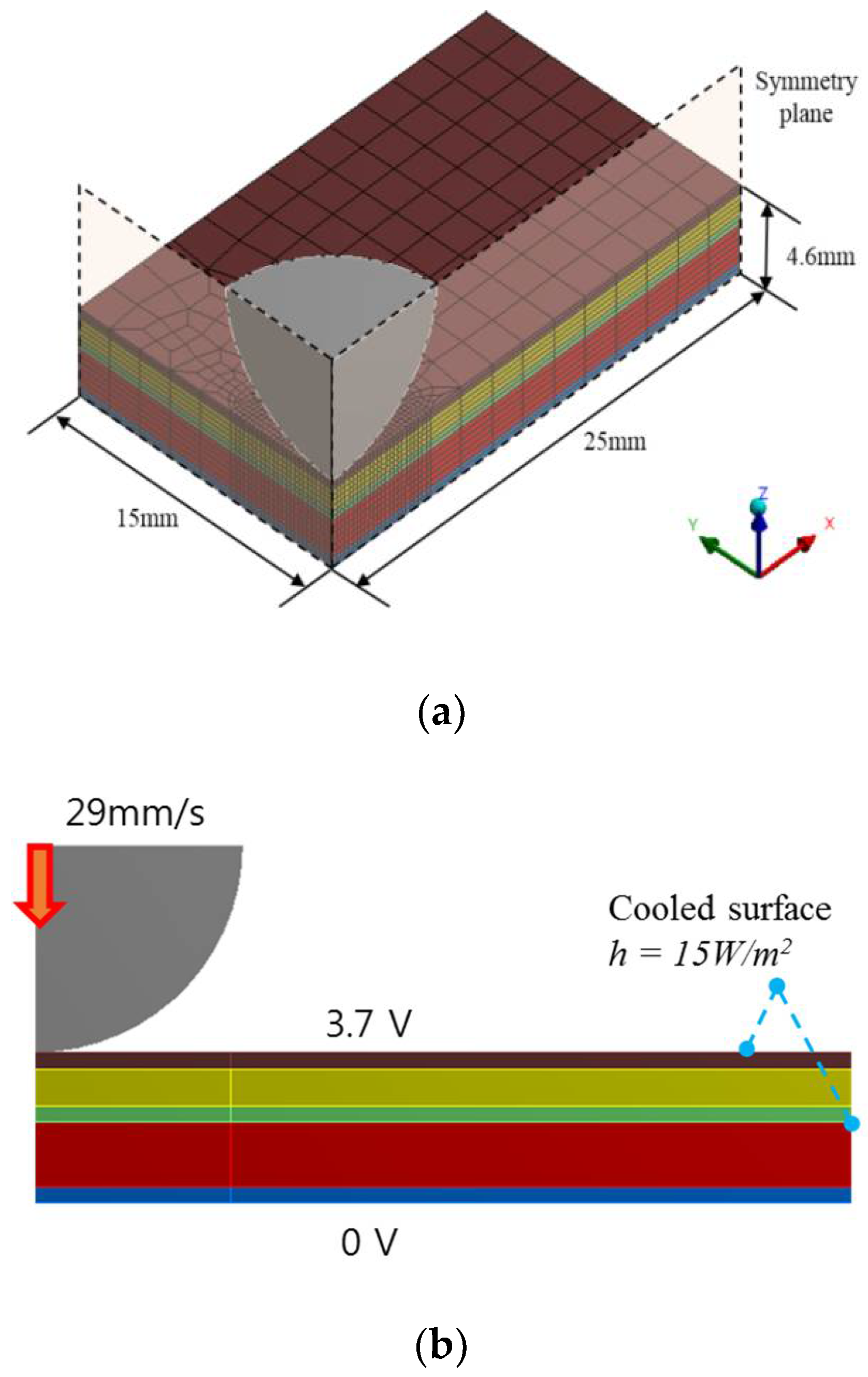
The finite element model of the LIB cell was constructed using the representative-sandwich (RS) model [
8,
9]. The RS model consists of a pouch cell composed of about 165 layers with 5 representative layers (positive current collector, positive electrode, separator, negative electrode, negative current collector) and has mechanical properties similar to the full model using all 165 layers. In addition, it is possible to accurately predict an internal short circuit due to failure of the separator.
Figure 3a shows the finite element model used for numerical analysis. The indenter is a rigid body, and the 1/4 model was used in consideration of symmetry.
2.2. Material Properties
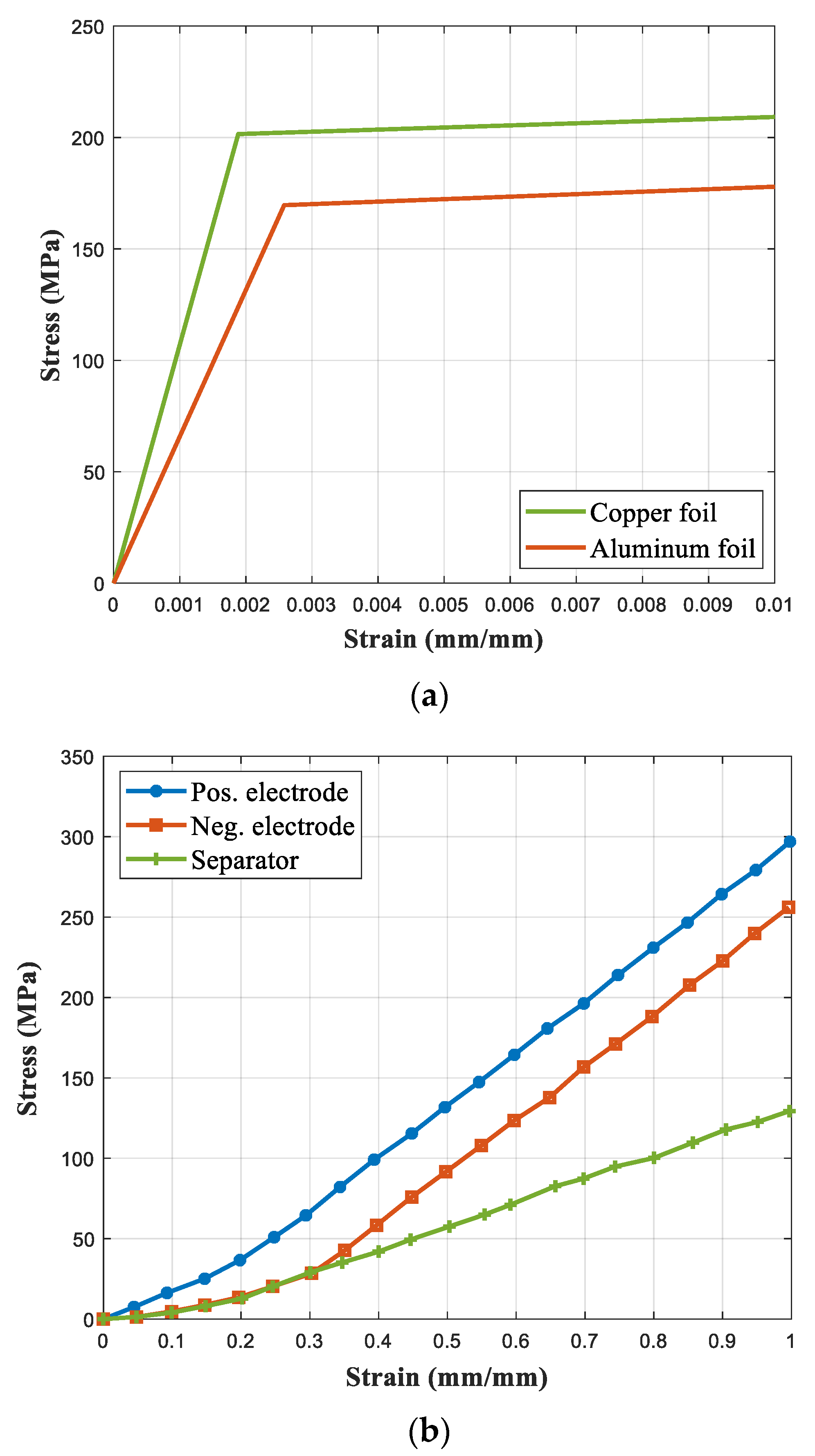
Figure 4 shows the stress–strain curves of five materials constituting the LIB cell: positive current collector, negative current collector, positive electrode, negative electrode, and separator.
The positive current collector and the negative current collector are Al foil and Cu foil, and the linear hardening property in plastic domain is applied using bilinear isotropic hardening model. The positive and negative electrodes are LiMnO4 and LiC6, respectively [
20]. Since the positive electrode, negative electrode, and separator have microporosity, the structural response is complicated, and it is difficult to obtain accurate physical properties. Therefore, the stress–strain curve theoretically derived from the load–displacement curve obtained through the experiment was used, and the multi-linear isotropic hardening plastic model with non-linear hardening properties was applied to the plastic region [
9].
In order to perform mechanical-electrical-thermal coupled analysis, not only mechanical properties such as density, elastic modulus, Poisson’s ratio, and coefficient of thermal expansion, but also electrical properties indicating specific resistance and thermal properties such as specific heat and thermal conductivity are required. The mechanical, electrical, and thermal properties of each component were referred to in previous studies [
9,
20].
Table 1 shows the material properties used in this paper.
2.3. Separator’s Failure Criterion
In order to predict the starting point of an internal short circuit, it is necessary to determine the failure criterion of the separator. However, there is a limit to determine the failure criterion through material tests of the separator only. Through experiments, Sahraei and Wierzbicki observed that when an internal short circuit occurred under the indentation test conditions, a decrease in reaction force, a decrease in voltage, and a rise in temperature occurred simultaneously [
12]. Through a parametric study, Zhang et al. found a failure strain showing a force–global strain curve similar to the experimental results of Sahraei and Wierzbicki and defined it as the failure criterion of the separator [
8,
9].
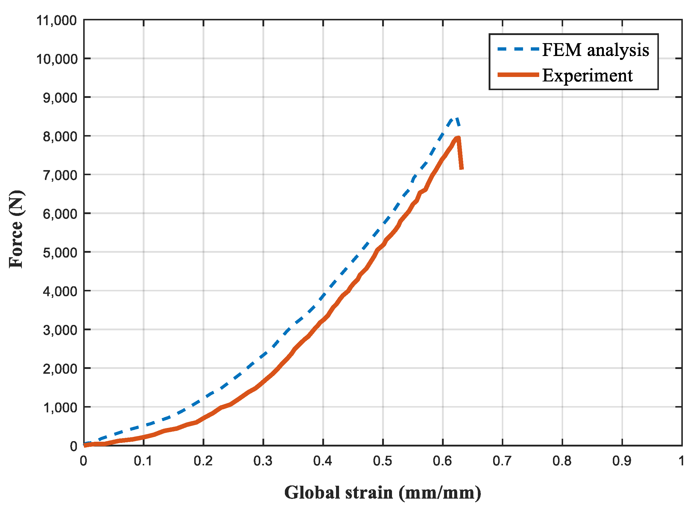
The equivalent strain was calculated using global strain [
21]. The equivalent strain exceeding the yield point is called the equivalent plastic strain. As a result of FEM analysis, when the global strain was 0.63 and the equivalent plastic strain was 1.98 under the indentation condition of a hemispherical indenter with a diameter of 12.7 mm, the force decreased at the same time as the experimental results of Sahraei and Wierzbicki. Therefore, it was defined as the failure criterion of the separator and applied to the mechanical-electrical-thermal coupled analysis.
Figure 5 shows the force–global strain curve measured experimentally and the force–global strain curve calculated by FEM analysis. Considering the indentation test results, the FEM analysis could accurately predict the starting point of internal short circuit with an error of 0.6%.
3. Results and Discussion
3.1. Mechanical Response
In the mechanical field, the starting point of the internal short circuit was predicted for the cylindrical indenter with a diameter of 6.35 mm, a hemispherical indenter with a diameter of 12.7 mm, and a 120° conical indenter, and the area of the internal short circuit was calculated. The starting point of internal short circuit was calculated as the point at which the force rapidly decreased in the stress–strain curve, and the internal short circuit area was calculated as the sum of the areas of the elements satisfying the separator failure condition.
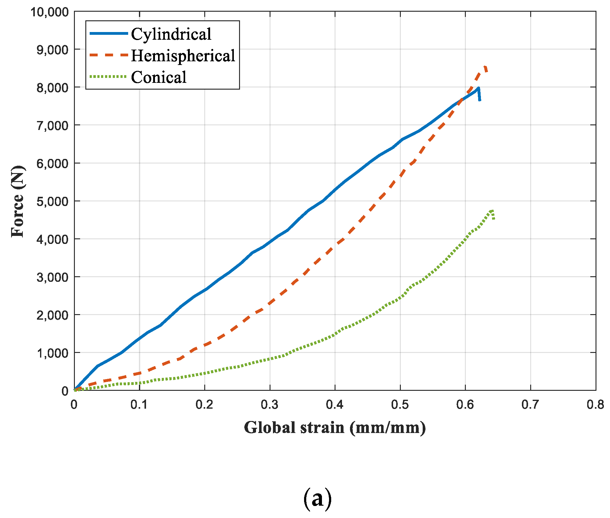
Figure 6a shows the force–strain curve with various indenters. Analyzing the starting point of the force drop, it can be seen that the internal short circuit occurred in the order of cylindrical, hemispherical, and conical indenters. When analyzing the overall force magnitude, the force received by the LIB cell is the largest in the order of cylindrical, hemispherical, and conical indenters.
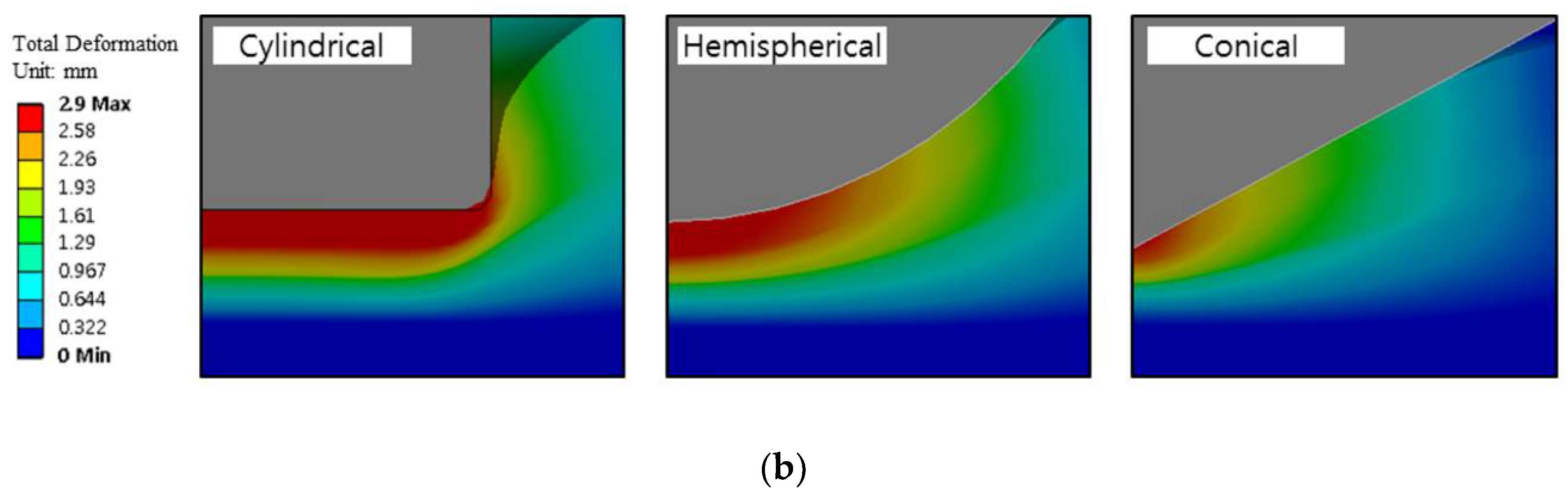
Figure 6b shows the deformation shape of the LIB cell with various indenters. It can be seen that an internal short circuit occurs at the edge of the indenter when pressed with a cylindrical indenter, and an internal short circuit occurs at the center of the indenter when pressed with a hemispherical indenter and a conical indenter.
Table 2 shows the indentation depth and internal short circuit area at the starting point of internal short circuit for the three indenters. When the LIB cell was pressed by a cylindrical indenter, the indentation depth at the starting point of the internal short circuit was 2.85 mm, and the internal short circuit area was calculated to be 2.25
. In the case of the hemispherical indenter, the internal short circuit occurred when the indentation depth was 2.9 mm, as in the experimental value, and the internal short circuit area was 0.375
. In the case of the conical indenter, the indentation depth when the internal short circuit occurred was 2.96 mm, and the internal short circuit area was 0.63
.
In this paper, three different indenters were pressed into the LIB cell at the same speed, and the analysis was performed until an internal short circuit occurred. The internal short circuit area is the area where the calculated strain is greater than the failure strain. When the LIB cell is pressed with the indenter, the small depth of the indenter into the LIB cell means that an internal short circuit occurs quickly. The sharpness of the indenter is in the following order: conical, hemispherical, cylindrical indenter. The sharper the indenter, the greater the depth the indenter enters into the LIB cell. As the depth into which the indenter enters the LIB cell increases, the force pressing the LIB cell decreases. As the force pressing the LIB cell decreases, the internal short circuit area becomes smaller. When the LIB cell is pressed with the sharpest conical indenter, the smallest force is applied to the LIB cell. Therefore, the conical indenter was the last of the three indenters for the internal short circuit to occur, and the internal short circuit area is the smallest. Since the hemispherical indenter is sharper than the cylindrical indenter, the force that the hemispherical indenter exerts on the LIB cell is smaller than that of the cylindrical indenter. Therefore, the internal short circuit occurs later, and the internal short circuit area is smaller when the LIB cell is pressed with the hemispherical indenter compared to when the LIB cell is pressed with the cylindrical indenter.
3.2. Electrical Response
In the electric field, internal voltage, current and Joule heat were calculated.
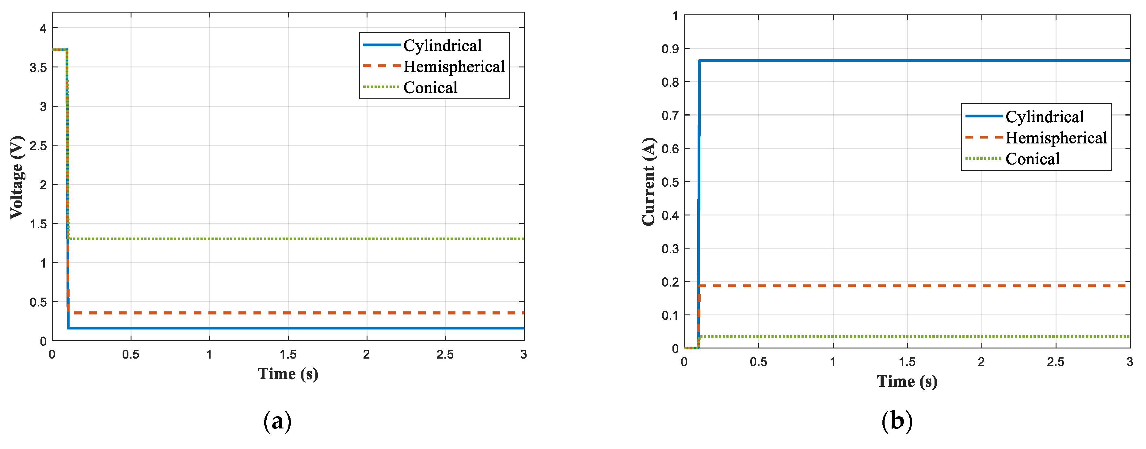
Figure 7a shows the voltage curve for the three indenters, and
Figure 7b shows the current graph for the three indenters. After the internal short circuit, it can be seen that the internal voltage drops sharply, while the current flowing into the internal short circuit increases rapidly.
Table 3 shows the internal voltage, current, and Joule heat with various indenters. In the case of indentation with a cylindrical indenter, an internal voltage of 0.17 V, a current of 0.86 A, and Joule heat of 0.149 mW were calculated. In the case of indentation with a hemispherical indenter, an internal voltage of 0.35 V, a current of 0.19 A, and Joule heat of 0.0042 mW were calculated. In the case of indentation with a conical indenter, an internal voltage of 1.28 V, a current of 0.03 A, and Joule heat of 0.008 mW were calculated.
The internal voltage is lowered as the separator with high specific resistance fails. As the internal short circuit area increases, the area of the failed separator also increases; thus, the resistance is lowered. When the resistance is lowered, the internal voltage decreases and the current flowing into the internal shorting layer increases. The Joule heat is proportional to the square of the current and inversely proportional to the resistance. When an internal short circuit occurs, the resistance decreases but the current increases more significantly. Therefore, the Joule heat shows a larger value as the internal short circuit area increases. Therefore, the voltage drop, the current flowing to the inner short circuit layer, and the Joule heat is large in the order of a cylindrical, hemispherical, and conical indenter with a large internal short circuit area.
3.3. Thermal Response
In the thermal field, the temperature of the LIB was calculated using Joule heat generated in the internal short circuit layer.
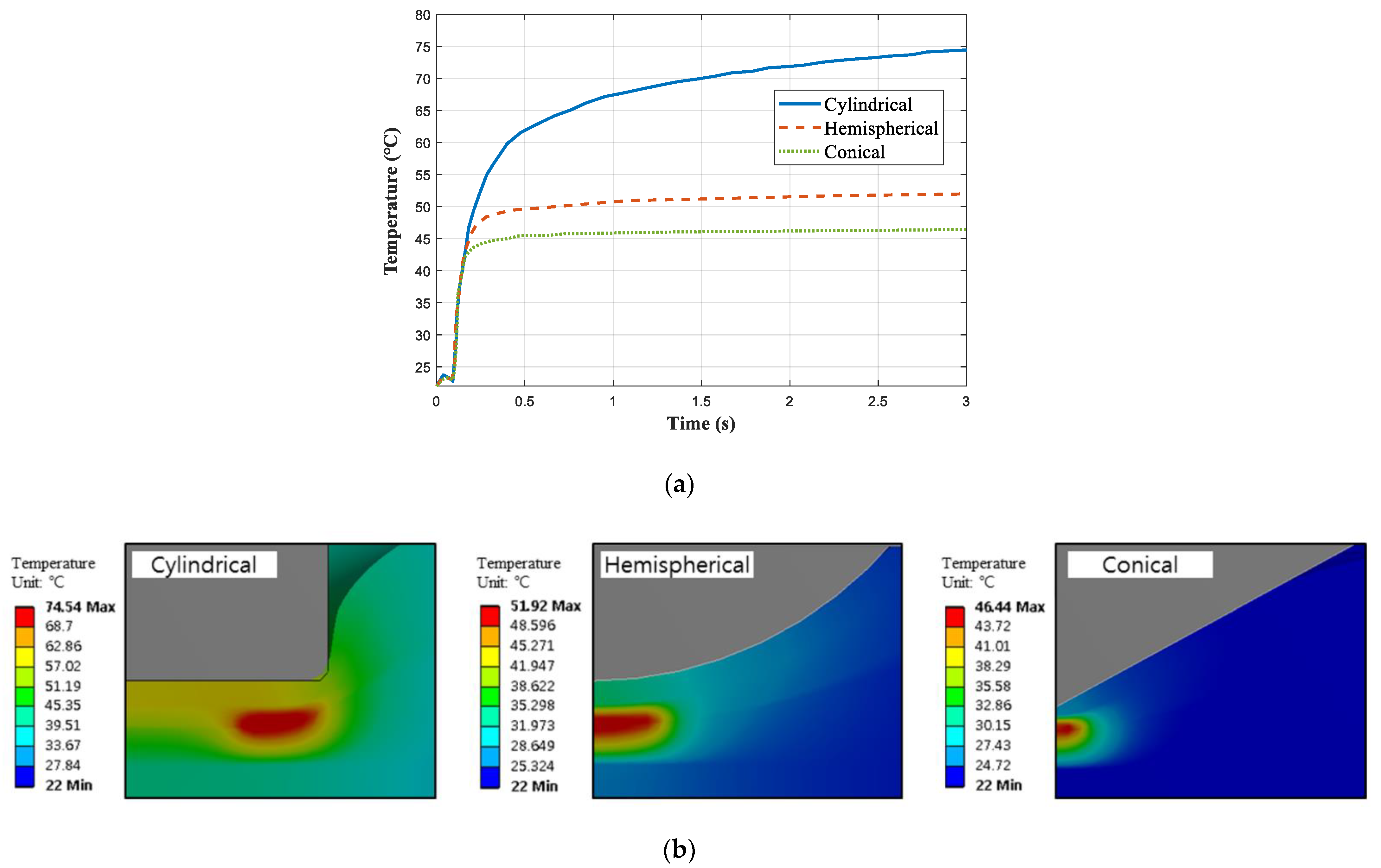
Figure 8a shows the temperature over time for each of the three indenters. It can be seen that the temperature rises rapidly from the moment when the internal short circuit occurs.
Figure 8b shows the temperature distribution for each of the three indenters. In the case of the cylindrical indenter, the highest temperature was calculated at the edge of the indenter, and in the case of the hemispherical indenter and the conical indenter, the highest temperature was found at the center of the cell.
Table 4 shows the maximum temperature with the various indenters. In the case of indentation with a cylindrical indenter, the maximum temperature was calculated as 74.5 °C; in the case of a hemispherical indenter, the maximum temperature was 51.9 °C, and in the case of a conical indenter, the maximum temperature was calculated as 46.4 °C. The temperature of the LIB cell appears higher as the Joule heat increases. The greater the internal short circuit area, the greater the Joule heat occurs; thus, the maximum temperature appears higher in the order of cylindrical, hemispherical, and conical indenters.
4. Conclusions
In this paper, the starting point of the internal short circuit for the LIB cell was predicted using a two-way mechanical-electrical-thermal coupled analysis method. In addition, mechanical responses of the LIB cell, such as the indentation depth and internal short circuit area for various indenters, were analyzed, and the effects of the internal short circuit area on the electrical and thermal responses of the LIB cell were analyzed.
The starting point of the internal short circuit calculated by FEM analysis was accurately predicted with an error of 0.6% in comparison with the experimental results. The indentation depth and internal short circuit area were calculated for cylindrical, hemispherical, and conical indenters. The duller the indenter, the faster the internal short circuit occurred, and the greater the internal short circuit area. When the LIB cell was pressed using the dullest cylindrical indenter, the indentation depth was the shortest at 2.85 mm, and the internal short circuit area was the largest at 2.25 . When the LIB cell was pressed using the hemispherical indenter, which is the second dullest after the cylindrical indenter, the indentation depth was 2.9 mm, which was the second shortest and the internal short area was 0.375 , which was the second greatest. When the LIB cell was pressed by the sharpest conical indenter, the indentation depth was the greatest at 2.96 mm, and the internal short circuit area was the smallest at 0.063 . In the electric field, the current, voltage drop, and Joule heat were calculated, and they were analyzed for the internal short circuit area. When the LIB cell was pressed by a cylindrical indenter, the current was 0.86 A, the voltage drop was 3.53 V, and the Joule heat was 0.149 mW. As a result of analyzing the effects of the internal short circuit area on the electrical responses, it was found that the greater the internal short circuit area, the greater the current, voltage drop, and Joule heat. In the thermal field, the maximum temperature and temperature gradient of the LIB cell due to Joule heat were calculated. In addition, the effect of the internal short circuit area on the maximum temperature was analyzed. When the LIB cell was pressed with a cylindrical indenter, the maximum temperature of LIB cell was calculated to be 74.5 °C. As a result of analyzing the maximum temperature of the LIB cell for the internal short circuit area, it was found that the greater the internal short circuit area, the higher the maximum temperature.
In conclusion, when the LIB cell was pressed with the dullest cylindrical indenter, the internal short circuit occurred the fastest, and the internal short circuit area was the greatest. The greater the internal short circuit area, the larger the current, voltage drop, and Joule heat, and the higher the maximum temperature. The results of this study are expected to be utilized to improve the mechanical safety of LIB cells due to external impacts.


