
Design and Control of Modular Multilevel Converter for Voltage Sag Mitigation


1
Electrical Engineering Department, Bahria University Karachi Campus, Karachi 75260, Pakistan
2
Department of Computer System and Technology, Faculty of Computer Science and Information Technology, Universiti Malaya, Kuala Lampur 50603, Malaysia
3
Department of Computer Science, College of Computers and Information Technology, Taif University, P.O. Box 11099, Taif 21944, Saudi Arabia
4
Department of Computer Engineering, College of Computers and Information Technology, Taif University, P.O. Box 11099, Taif 21944, Saudi Arabia
*
Author to whom correspondence should be addressed.
Energies 2022, 15(5), 1681; https://doi.org/10.3390/en15051681
Submission received: 8 January 2022
/
Revised: 9 February 2022
/
Accepted: 18 February 2022
/
Published: 24 February 2022
(This article belongs to the Topic Application of Innovative Power Electronic Technologies)
Abstract
:Voltage sag in a power system is an unavoidable power quality issue, and it is also an urgent concern of sensitive industrial users. To ensure the power quality demand and economical operation of the power system, voltage sag management has always drawn great attention from researchers around the world. The latest research that realizes the power quality conditioning has used dynamic voltage restorers (DVRs), static VAR compensator (SVCs), adaptive neuro-fuzzy inference systems (ANFISs), and fuzzy logic controllers based on DVR to mitigate voltage sag. These devices, methods, and control strategies that have been recently used for voltage sag mitigation have some limitations, including high cost, increased complexity, and lower performance. This article proposes a novel, efficient, reliable, and cost-effective voltage sag mitigation scheme based on a modular multilevel converter (MMC) that ensures effective power delivery at nominal power under transient voltage conditions. The proposed method, the MMC, compensates for the energy loss caused by voltage sags using its internal energy storage of the submodules, and ensures reliable power delivery to the load distribution system. Furthermore, control strategies are developed for the MMC to control DC voltage, AC voltage, active power, and circulating current. Detailed system mathematical models of controllers are developed in the dual synchronous reference frame (DSRF). Validation of the results of back-to-back MMC for dynamic load distribution system is analyzed which proves the effectiveness of the proposed scheme for voltage sag mitigation.
1. Introduction
Voltage sag is one of the major concerns of the modern industry, as it can interrupt sensitive electrical loads and in the worst case cause production problems. According to the official definition of voltage sag, “It is the phenomenon in which the magnitude of voltage is reduced below 10% of nominal RMS value over a time ranging from one half-cycle to one minute” [1]. A voltage sag is defined by IEEE standard 1159–1995 as “A decrease in the RMS voltage from 10% to 90% of nominal value for the duration of 0.5 cycles to 1 min” [2]. Time duration and voltage drop for voltage sag differ from one grid code to another. According to different countries’ grid codes and regulations, different limits are allowed for voltage drop and time duration in case of voltage sag events, as shown in Table 1 [3].
It is one of the serious power quality challenges that are caused by faults, energization of heavy distribution feeders, and abrupt rise of heavy load. Voltage sag can damage sensitive industrial load equipment and create high power losses in power systems [4]. Different devices, methods, and control strategies were used, i.e., dynamic voltage restorer (DVR) in [5], static VAR compensator (SVC) in [6], ANFIS-based UPQC in [7], and fuzzy logic controller based DVR in [8], to mitigate voltage sag and to address power quality conditioning of load distribution system.
1.1. Voltage Sag Mitigation Based on Various Technologies
Power system quality has gained a lot of interest over the last decade. There are a variety of devices and control methods used to mitigate the risks associated with power quality in the power system. Different technologies and methods are developed based on power system quality to control the voltage sag of the AC grid system.
1.1.1. Dynamic Voltage Restore (DVR)
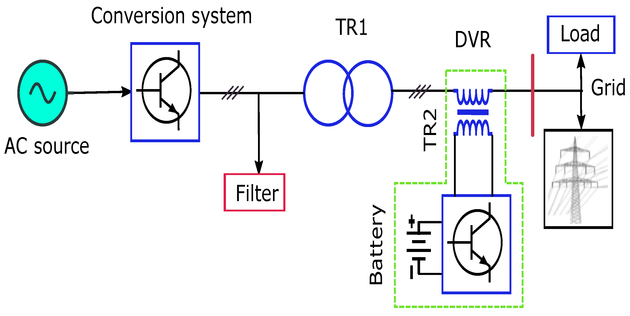
Dynamic voltage restorer is the device that ensures optimal power system performance while minimizing the adverse effects of voltage sags, harmonics, unbalanced voltages, and voltage swells. A DVR includes four components, i.e., voltage source inverter, energy storage system, passive filters, and injection transformer (IT), as illustrated in Figure 1. In ref. [9], a DVR is used to inject three-phase voltages in series with grid voltage to compensate for voltage disturbances caused by asymmetrical faults.
It maintains nominal voltages at the point of connection and compensates voltage sag, harmonics, and voltage unbalance. Nevertheless, some limitations in terms of low-voltage ride-through still exist. Ref. [5] mitigated voltage sag effectively during different types of grid faults using an efficient dynamic voltage restorer (DVR) since its cost is high and it has high complexity. In ref. [10], a fuzzy logic controller-based dynamic voltage restorer was designed that mitigates voltage sag up to 50%, but the system has the limitation of the frequency fluctuation. The DVR in ref. [11] mitigates voltage sag, voltage unbalance factor to less than one percent, and voltage total harmonic distortion to less than five percent.
1.1.2. Static VAR Compensator (SVC)
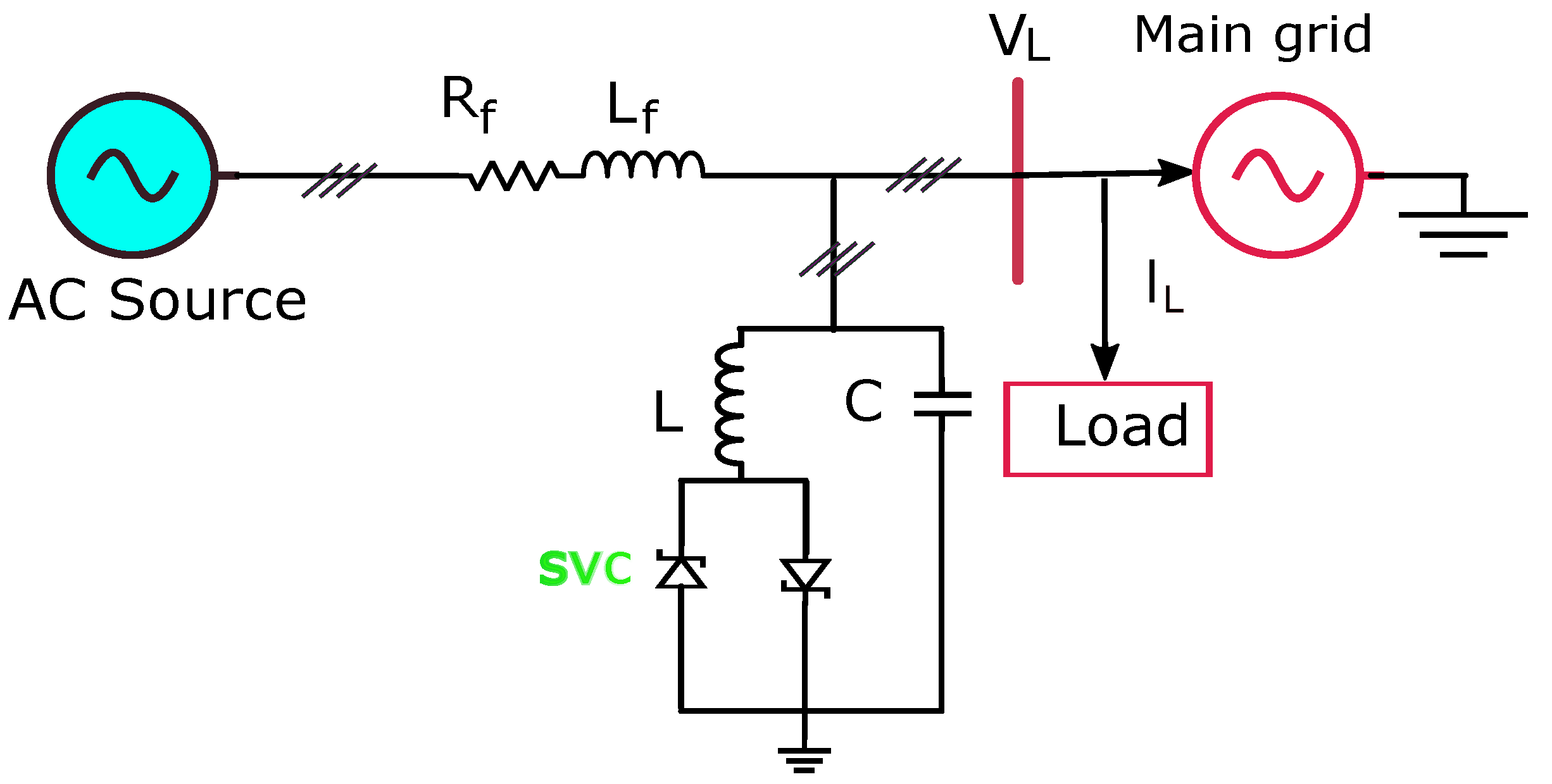
In an electrical power system, a static VAR compensator controls parameters such as bus voltage by utilizing static VAR generators or absorbers. It is a flexible AC transmission system device as shown in Figure 2, which has been extensively used in recent years to rectify various power quality problems caused by faults causing voltage sags in the system. In ref. [12], the authors compared static VAR compensators’ effectiveness for managing voltage sag events and concluded that SVC contributes the least to transient margin (TM). In ref. [6], the static VAR compensator is used in the AC grid system to enhance power quality and ensure power efficiency, but its performance was lower than that of STATCOM and DVR.
1.1.3. Unified Power Quality Conditioner
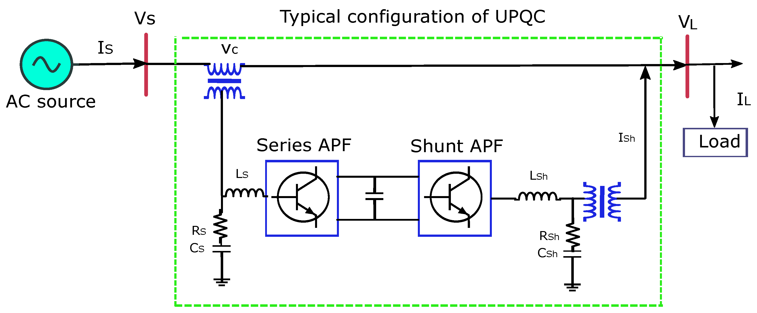
Similar to a DVR, UPQC has the capability of dealing with power quality issues of the power system, such as harmonics and voltage fluctuations. It is designed to enhance power system performance while minimizing disturbances that adversely affect the performance of critical loads. In addition to regulating the flow of power, UPQCs compensate for harmonics, reactive power, and voltage disturbances. A UPQC contains two voltage source converters linked with a common DC link in a single-phase/three-phase configuration. In Figure 3, the UPQC combines shunt and series controllers into one DC bus. Shunt controllers can produce or absorb reactive power at the common point of coupling.
Accordingly, the series controller is connected to the AC grid systems and controls the parameters of the lines, as it is described in detail in [13]. Ref. [14] used UPQC with the fuzzy logic controller to minimize voltage sag and current harmonics. Its results indicate a reduction in a harmonic distortion from 8.93% to 3.34%. According to [15], UPQC is used in a hybrid PV and wind system microgrid to reduce voltage sag and swell by using reactive current injection or absorption. Ref. [7] apply an adaptive neuro-fuzzy interference system (ANFIS) based on a unified power quality conditioner (UPQC) to address voltage sag mitigation and THD reduction since it is costly and quite complex. A power quality controller will additionally compensate for voltage sags, surges, and harmonics, and will limit voltage imbalance in microgrids that are linked to the main grids in the ref. [16]. Table 2 presents a comparison between the various popular technologies used for voltage sag mitigation.
The comparison of different voltage sag mitigation technologies includes cost, rating, and various aspects of performance. In conclusion, a DVR provides superior stability to that of SVC in terms of voltage sag, voltage swell, and voltage fluctuation mitigation, while UPQC provides superior protection against poor-quality sources for sensitive loads. The different control methods and devices used to mitigate voltage sag, mentioned in Table 2, has some limitations, i.e., increased complexity, high cost, and lower performance.
Modular multilevel converter (MMC) is an emerging and state-of-the-art power electronic-based technology first introduced in ref. [17]. It has the potential of scalability to meet voltage level requirements, low level of power losses, high reliability, enhanced efficiency, and better harmonic suppression quality [18,19,20]. It requires the grid side filter to be smaller in size since it has lower harmonics in its output voltage [21]. A modular multilevel converter is an ideal converter with the flexibility of hundreds of output voltage levels for high-voltage three-phase motor drives [22], electric railways, and high-voltage transmission [23]. To address the limitations of the above methods and control strategies mentioned for voltage sag mitigation technologies in Table 2, the MMC can be designed to operate continuously in islanded mode with satisfactory power quality. The voltage sag in the upstream AC grid system caused by asymmetrical faults can be successfully mitigated by using the MMC to ensure satisfactory power delivery to the load distribution system. Using modern MMC technology, this paper presents a novel approach to efficiently mitigate voltage sag sustained in upstream AC grid systems.
1.2. Contributions
The following contributions are summarized in this paper:
- An analysis of an MMC component dimensioning and control system is provided, followed by a consideration of whether an MMC can be specifically designed for dynamic load distribution ensuring power quality.
- The article explores the feasibility and potential of the MMC to mitigate voltage sag due to asymmetrical fault in the upstream AC grid side and to deliver constant power to load distribution.
- The paper examines the effect of voltage sag of the magnitude of up to −60% for 75 ms in the upstream AC grid when using the internal energy storage of back-to-back modular multilevel converters.
1.3. Organization
The remainder of this article is organized as follows: Section 2 of this article explains the design principles of MMC, selection of characteristic parameters, component sizing, and all the relevant involved procedures in detail. Section 3 describes the proposed system in detail. Section 4 explains the mathematical modeling of different control systems of the MMC and the control strategies developed for the regulation of circulating current, active and reactive power, and AC and DC voltages of the MMC-rectifier and the MMC-inverter. Section 5 of this research article explains, in detail, the simulation results for the voltage sag mitigation strategy of the MMC and gives a comparison of the commonly employed and proposed control strategy for voltage sag mitigation. Section 6 concludes the research article.
2. MMC Component Design Principles
It requires extensive planning to design a modular multilevel converter, including sizing, and dimensioning of its components. The design procedure of the MMC includes determining the number of submodules (SMs) per arm, DC link voltage, submodule switching devices as per industrial standards and ratings, submodule capacitor’s capacitance, and arm inductance.
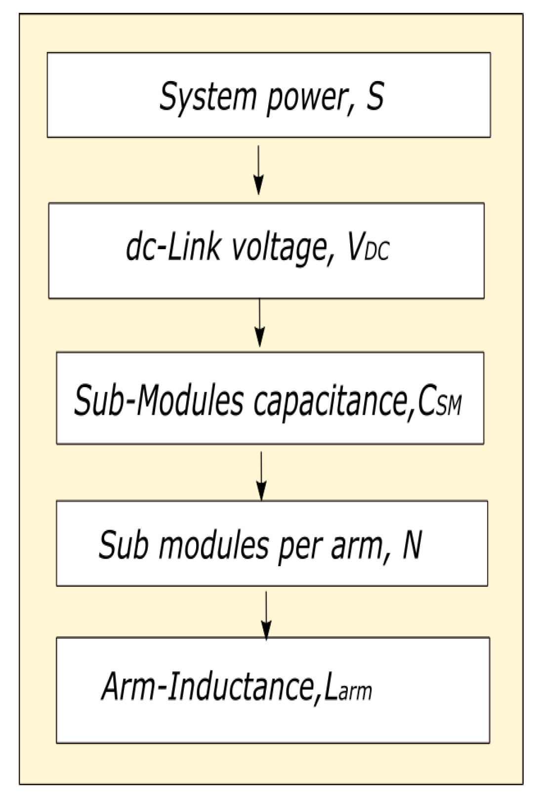
The flow chart of the MMC design is shown in Figure 4. Initially, it is required to determine the apparent power of MMC, which can be calculated by
The DC-link voltage of a modular multilevel converter determines the average voltage of a submodule capacitor. The ratings of semiconductor-based IGBT technology limit the average voltage of a submodule of the MMC. The DC-link voltage of the MMC can be determined by multiplying the average voltage of the capacitor with the total number of submodules per arm, taking into account standard current and voltage ratings of semiconductors. The submodule capacitor acts as an energy buffer, and its capacitance dimensioning is necessary for energy storage calculations. The capacitance of the capacitor of SM should be chosen with a low level of voltage ripples. The submodule capacitor must be dimensioned properly so that it allows the maximum arm current of the converter. Arm inductance of the MMC is required to limit the circulating current in the arms, short-circuit current, and to isolate the lower and upper arms of the MMC.
2.1. DC-Link Voltage of the MMC
According to the ideal relationship between the AC and DC side of the modular multilevel converter, without taking account of internal losses, this equation must hold.
where is
can be easily calculated from
The DC-link voltage of the modular multilevel converter has a direct relation with the RMS value of the AC grid line-to-line voltage and inverse proportion with the modulation index of the converter.
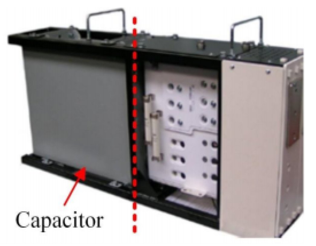
2.2. Submodule Capacitance,
The capacitor of the submodule (Figure 5) is the main component of the converter which acts as an energy buffer. Its sizing and dimensioning play a vital role while designing the submodule of the converter. The capacitor of the submodule is floating in nature owing to its charging and discharging by converter arm currents. The arm current causes inevitable voltage ripples, which have an inverse relation with the capacitance of the capacitor of the submodule.
Choosing a reasonable capacitance of capacitor for submodule can reduce the magnitude of voltage ripple. Capacitor voltage ripple can also be controlled by eliminating the harmonics in circulating currents. Selection of the arbitrary high value of capacitance of capacitor for submodule may be exorbitant and unnecessary. The value of can be calculated as proposed in [24].
where S is the apparent power of converter that is , N is the total number of submodules per arm, is voltage modulation index, is time average of submodule capacitor voltage, is the fundamental frequency, is ripple voltage of the capacitor (peak to average), and is the power factor of AC upstream grid side power factor. The above equation offers to derive the capacitance of capacitor ; only the voltage ripple of capacitor needs consideration in designing and dimensioning of the capacitor of submodule. In ref. [25], 10% voltage ripple of the capacitor of SM is considered suitable. Another approach in reference [25] that calculates the capacitance of the capacitor of SM by using the stored energy in all submodules is given by
To bring some abstraction and to ease in the comparison of different systems, energy–power ratio, E.P., is defined by
from the above equation of and energy to power ratio, the capacitance of the capacitor of the submodule can be written in terms of energy to power ratio, total number of submodules, apparent power, and DC-link voltage. Using energy–power ratio, the capacitance of the capacitor can be adjusted as
In ref. [25], 30–40 kJ/MVA energy is needed per converter station HVDC-based MMC, and 60–80 kJ/MVA for back to back converter system.
2.3. Determining of Submodules per Arm of MMC
The potential advantage of an MMC over a conventional VSC is its adaptability and scalability to different power and voltage levels. While designing the MMC for different power and voltage levels, the number of SMs per arm is one of the basic parameters to be determined. The selection of the number of submodules per arm plays an important role to handle the high voltage and power of the system. DC-link voltage is equally distributed to the “N” number of submodules of an arm, and the average voltage of a submodule capacitor is . The mathematical expression for determining the number of submodules is
To determine the number of submodules also needs a deep consideration of the selection of semiconductor ratings because semiconductors limit the voltage of submodules. Current and voltage ratings are the key parameters of the integrated gate bipolar transistor (IGBT) module. Today, commercially available semiconductor-based IGBT technology has limited kV ratings. The limitation of the kV ratings should be considered while determining the number of submodules. The semiconductor-based high-voltage IGBT module with the modules package available in the market is shown in Table 3.
In case of failure or damage of any submodule in either arm, redundant submodules should be provided to improve the reliability and stability of the system.
2.4. Arm’s Inductance,
The arm inductor of the MMC is also called outdoor air-core reactor, which has multiple functions in a modular multilevel converter. It allows the converter to control reactive power and second harmonic circulating current, and limits the rise of the current in short circuit conditions. The concept in ref. [26] is of an arm inductor forming a resonance frequency with submodule capacitance
In the above equation, n-th harmonic currents can only be limited by arm resistance. Modular multilevel converter should operate above the high value of resonant frequency (RF) which occurs at and . The harmonic number n is given by the equation . The above equation can be written as
The product of arm inductance and SM capacitance must have minimum value depending on operating frequency and the number of SM per arm:
Arm inductance also limits fault current in the case of DC-link short-circuit condition. It is affected by several factors, including the submodule capacitor voltage , the modulation technique, the switching frequency, and a controller optionally used for suppression of circulating current. Based on the literature, the typical value for arm inductance is 0.15 p.u. of base AC input in [27].
3. Proposed System Description
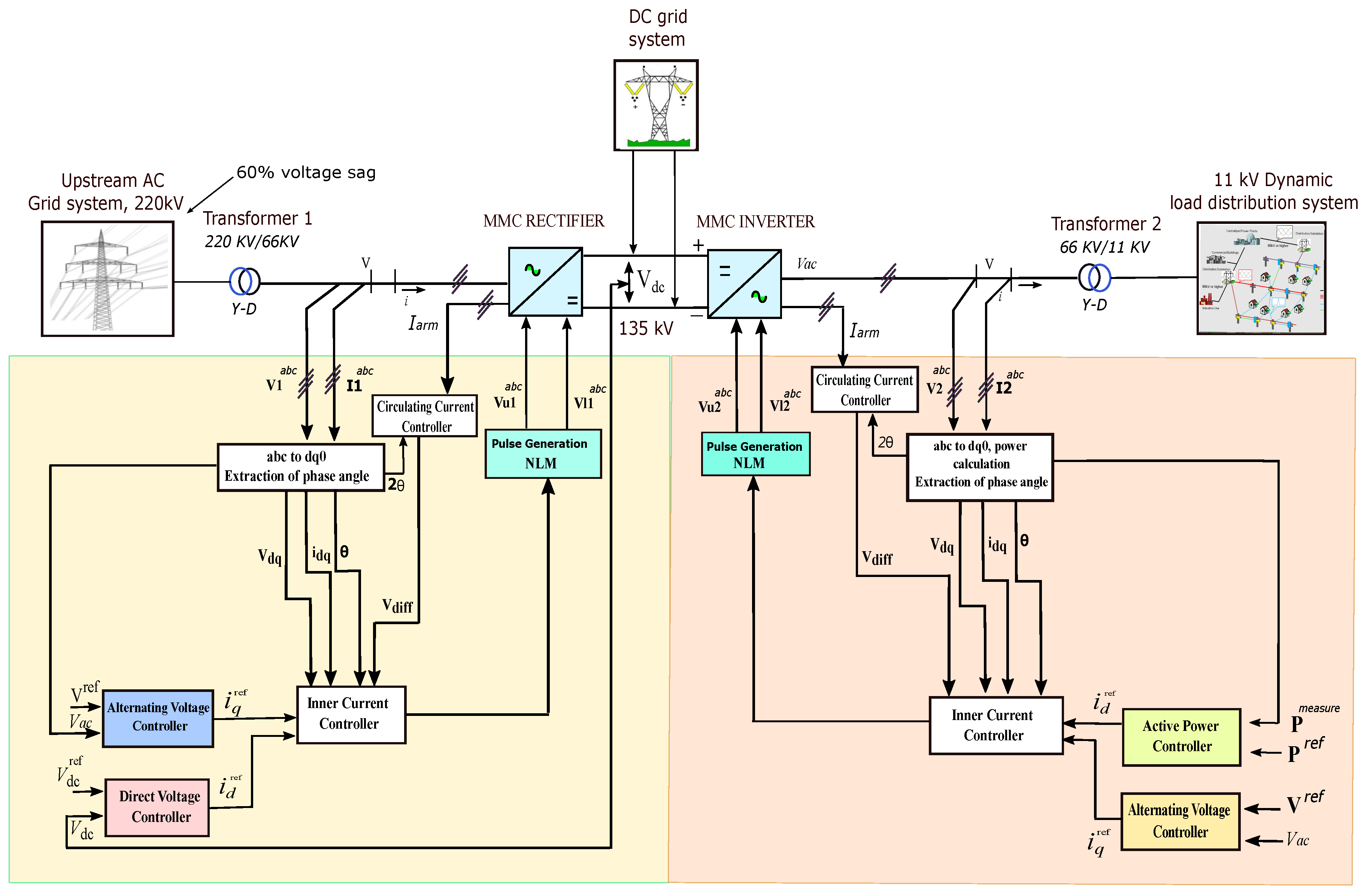
A system of back-to-back MMC that ensures the power quality demand of load distribution is shown in Figure 6. It consists of an upstream AC grid system, back-to-back MMC, DC grid system, and dynamic load distribution system. In the proposed system, we intend to explore the feasibility of the MMC for voltage sag mitigation and to achieve reliable power for load distribution. The concept and feasibility of the proposed system are to be proven through simulation results studies, showing the functionality of sag mitigation, effective control system, and quick response of the MMC converter. Characteristic parameters, component sizing, and dimensioning are performed as per design participles of MMCs described in Section 2 of this article.
A 10 MW/11 kV dynamic load distribution system is connected with 220 kV AC and 135 kV DC grid systems linked through the MMC-rectifier and the MMC-inverter. The MVA rating of the MMC-rectifier and the MMC-inverter is 220 MVA. The structure of the MMC is illustrated in Figure 7. The structure of the MMC contains six arms, each of them consisting of 60 submodules with a capacitance of 0.0105 p.u. and a series arm reactor with an inductance of 0.0164 p.u. The upstream 220 kV AC grid voltage is stepped down by core type (Y-D) power transformer to 66 kV and fed to the MMC-rectifier, which is linked with 135 kV DC grid system. The (Y-D) power transformers have the capability of limiting the zero-sequence current. Since the MMC will not experience zero-sequence current, the zero-sequence current controller is not necessary. A core type (Y-D) power transformer is used to step down MMC-inverter voltage from 66 kV to 11 kV, feeding the 10 MW dynamic load distribution system. The proposed system is built up to mitigate voltage sag occurring in upstream AC grid systems due to asymmetrical faults using the internal energy stored in the submodules of back-to-back MMC to compensate the voltage sag and to ensure satisfactory power delivery for the operation of dynamic load distribution.
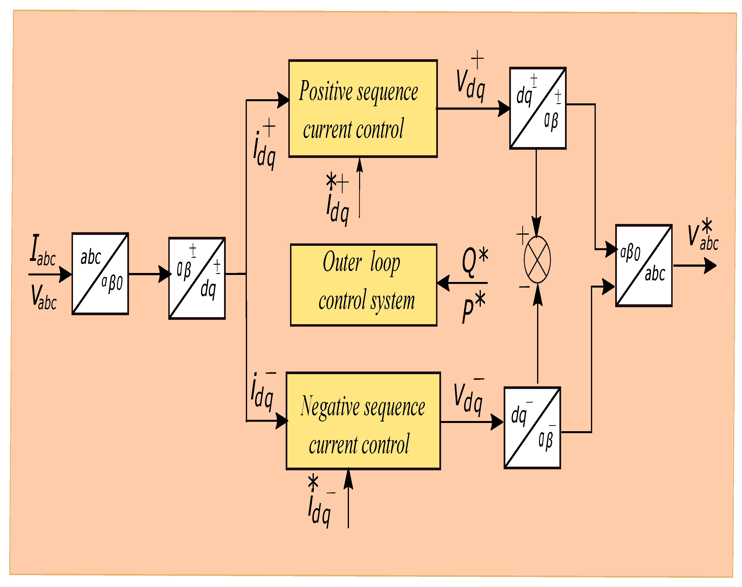
Therefore, to accomplish the principal objective of the proposed scheme, it requires an effective control system for quick response to the system. A dual synchronous reference frame (DSRF)-based current controller is developed for the current control mode of the MMC-rectifier and the MMC-inverter. The outer control loop for the MMC-rectifier consists of AC and DC voltage control, whereas AC voltage and active power control for the MMC-inverter. Circulating current suppression controller is designed to control the differential current in between the phases of modular multilevel converter which distorts the arm currents and increases the peak value of arm current causing system power losses.
During the unbalanced grid conditions, positive-sequence and negative-sequence current components exist which are fully controllable for an MMC. The controller for positive- and negative-sequence current components is illustrated in Figure 6.
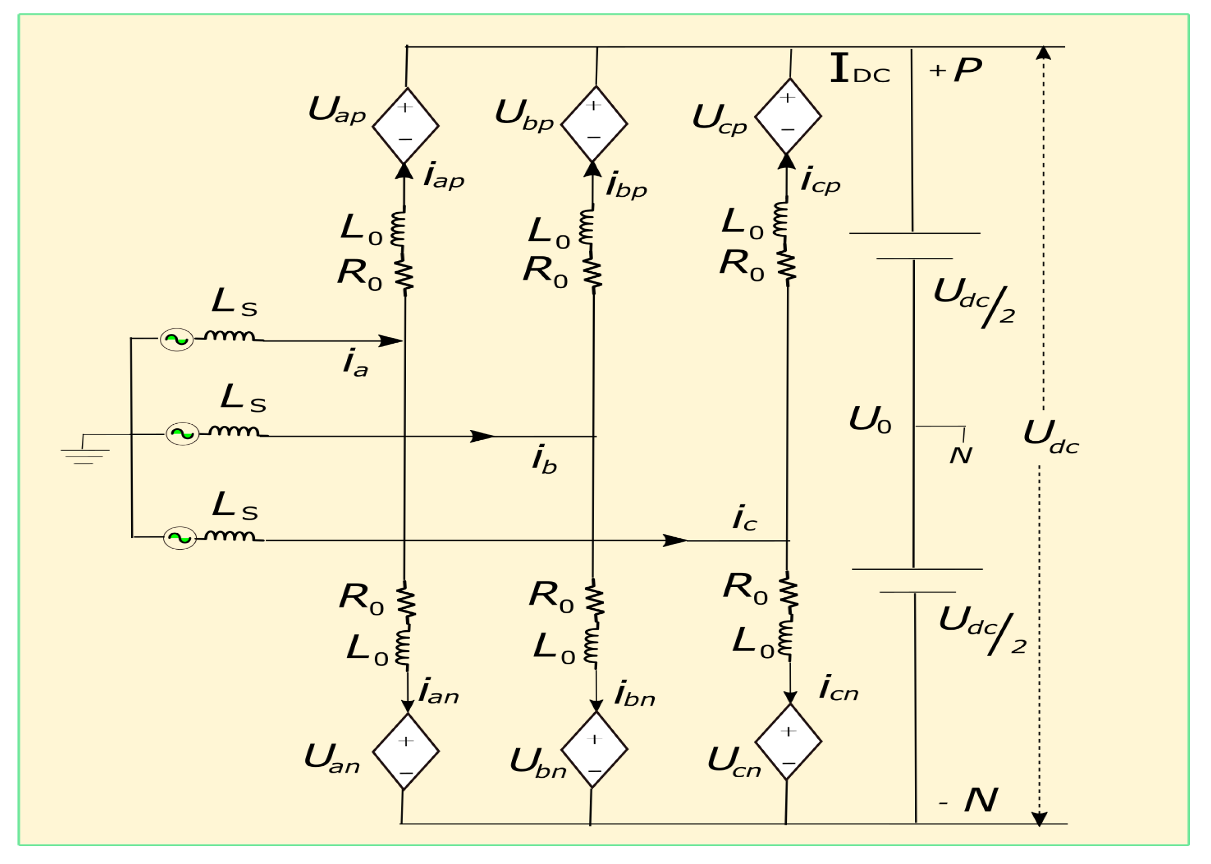
Moreover, for efficiency and accuracy in reproducing dynamic behavior, analytical and simulation reasons, and increasing performance for the analysis of converter response, we use the aggregate model of a modular multilevel converter. This MMC model relies on the assumption of perfect capacitor balancing. The equivalent circuit of the MMC for the mathematical modeling of system-level control design is illustrated in Figure 7. In an equivalent circuit of the MMC, , , and are the upper arm voltages, whereas , , and are lower arm voltages. , , and , , are the upper and lower arm currents in three-phase legs of the MMC. The sum of currents in the upper and lower arm of each phase of the MMC yields phase currents , , and .
The differential current in the arm of each phase is , , and given by
Currents in the upper arm and lower arm in terms of their difference are illustrated in the following equations:
Using Kirchhoff’s voltage law, the upper and lower arm phase voltages are
where , , and are phase voltages of the AC side of the converter, and is the DC voltage between the two poles. The voltage between two neutral points and ground is . Adding Equations (19) and (20) gives
Let , and are average of the difference between upper and lower voltages
Equation (22) mathematically presents the AC side of the MMC. Controllers are designed with this model in the following sections.
4. Control System Modeling
This section explains, in detail, the inner current loop and outer voltage loops designed for the MMC-rectifier and the MMC-inverter.
4.1. Inner Current Controller under Balanced Grid Conditions
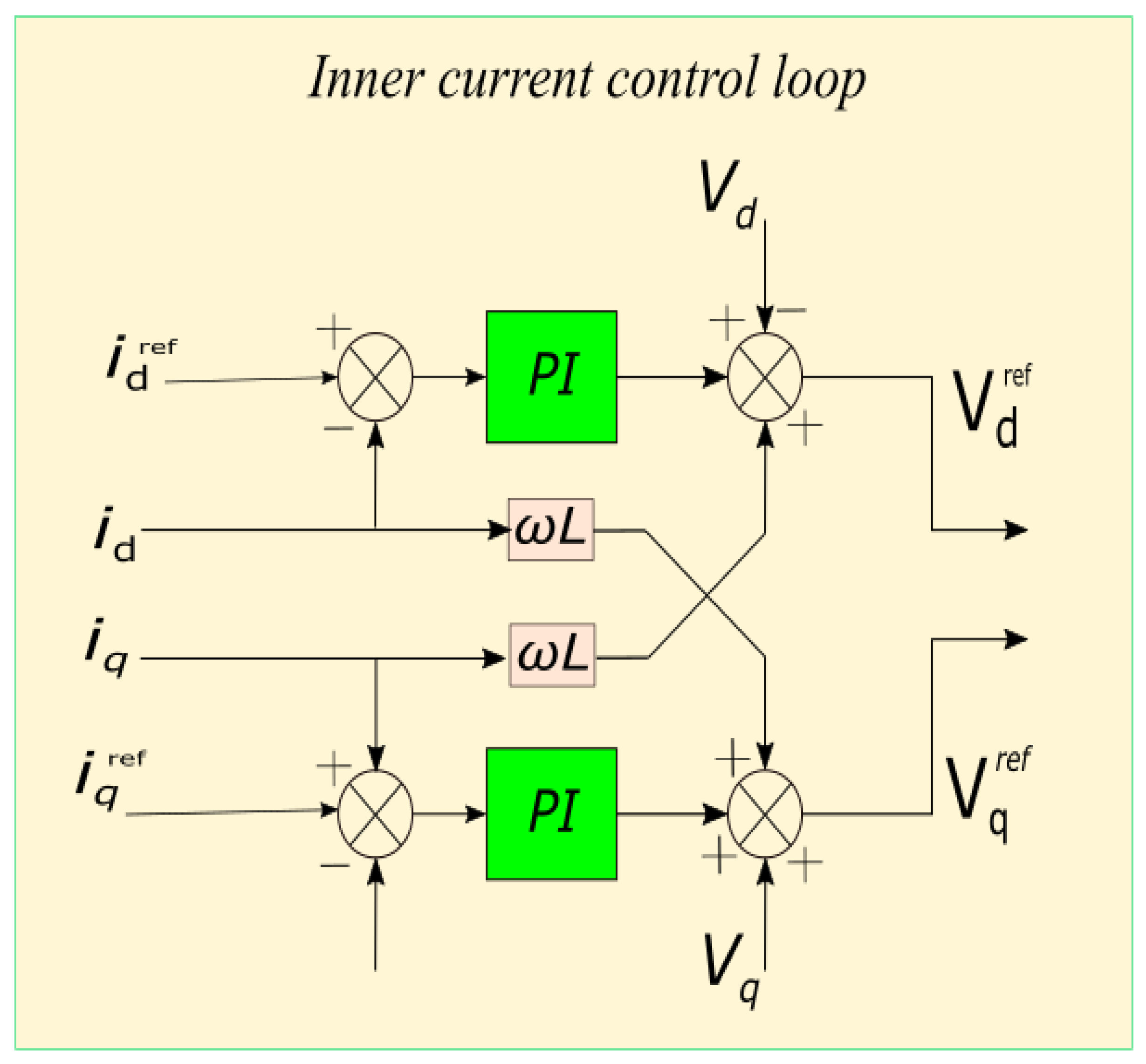
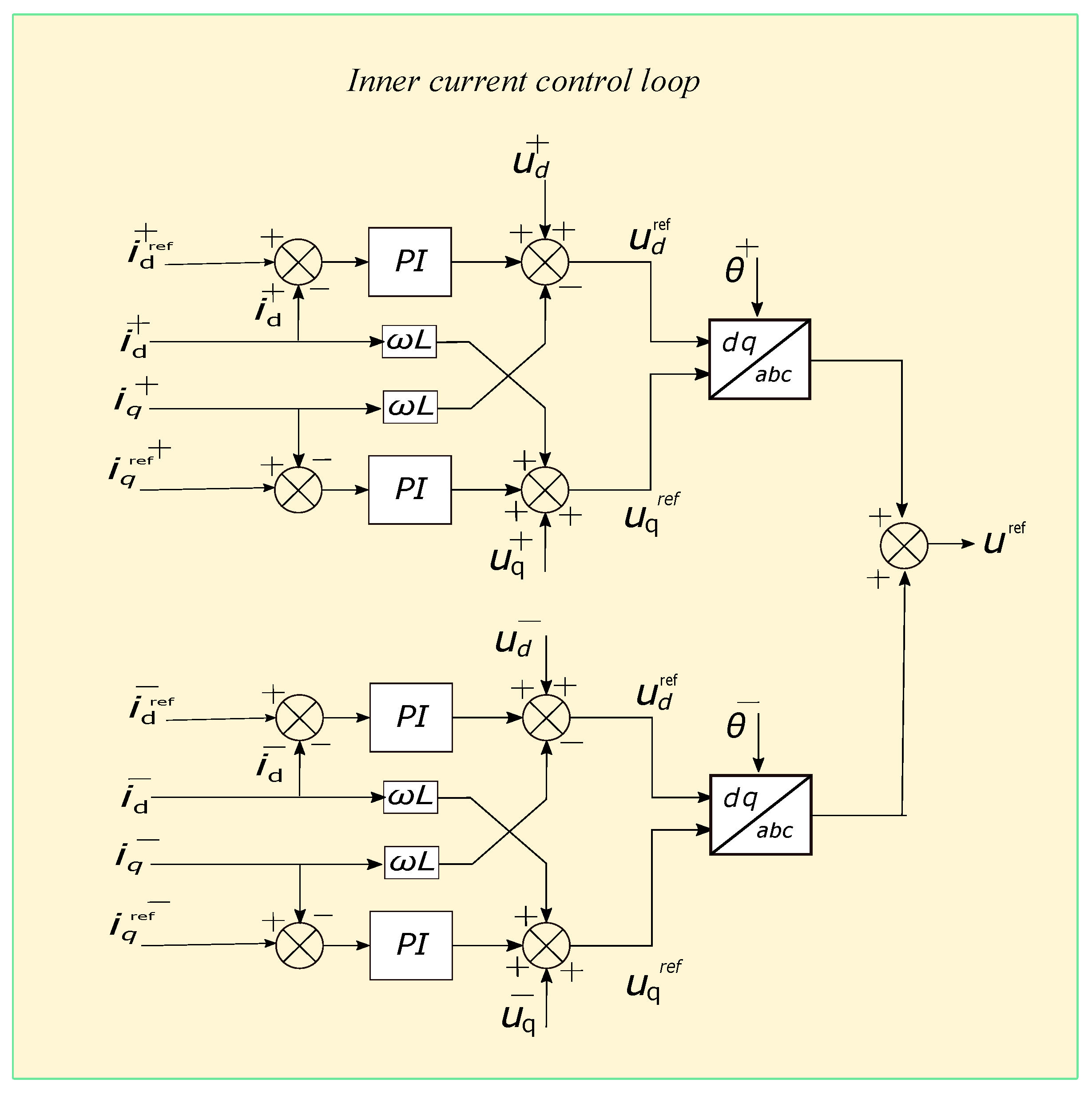
The inner current controller is the most fundamental part of the MMC control system, as shown in Figure 8. The controller is a built-in SRF with PLL to generate frequency and phase angle information for the measurement of AC voltages. A dq vector control method is used for generating the output voltage required for the inner current controller. Applying Park and Laplace transformation to Equation (22) yields
4.2. Inner Current Controller under Unbalanced Grid Conditions
When the grid is under unbalanced conditions, positive-, negative-, and zero-sequence components exist. These component needs to be controlled independently. These components are derived from Equation (22) and can be separated into three independent systems.
4.3. Positive- and Negative-Sequence Current Control
Applying Laplace transformation to and , the positive-sequence voltage of the MMC and and negative-sequence voltage and can be determined by following the proportional integral feedforward controller.
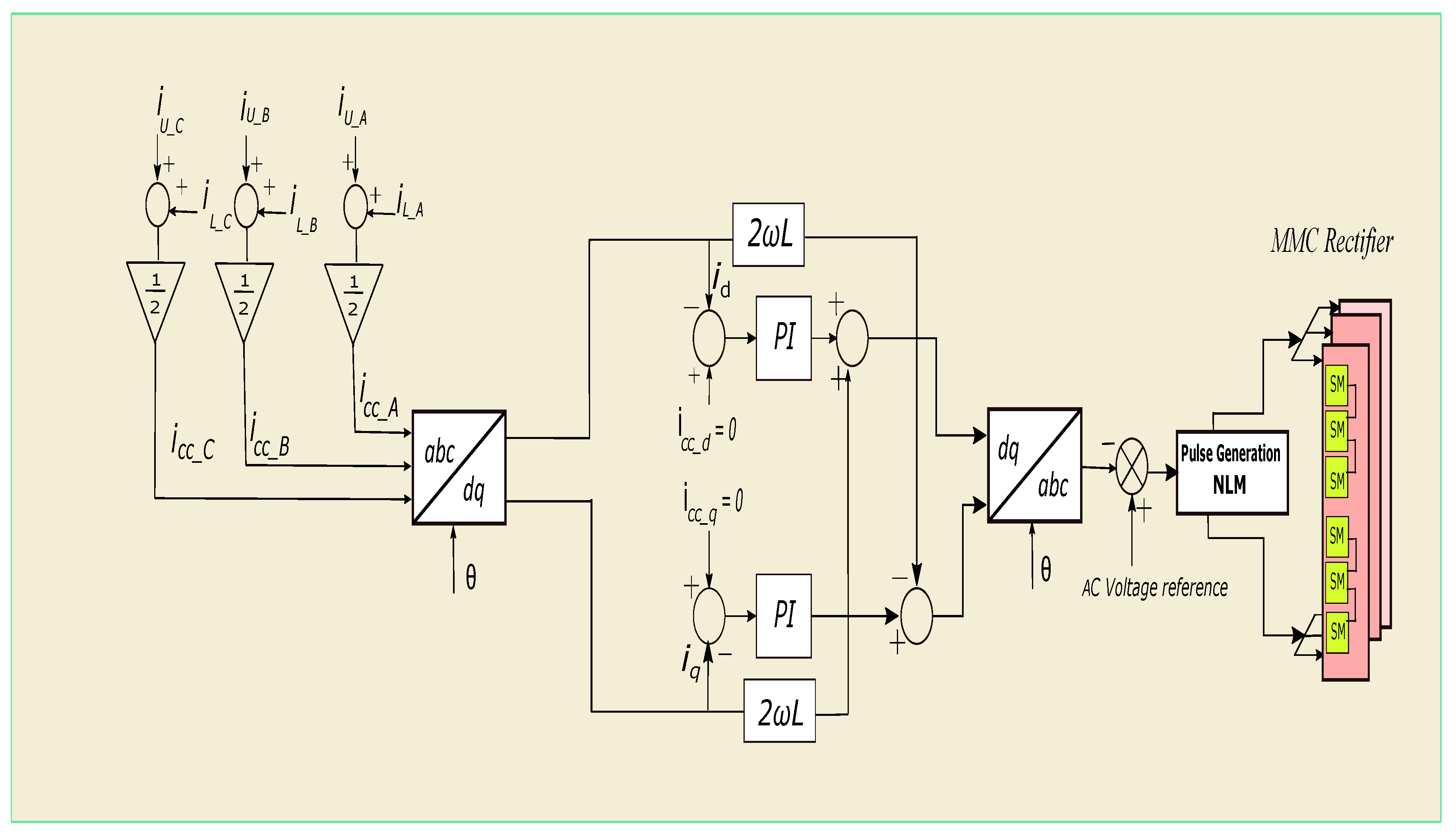
4.4. Circulating Current Suppression Control
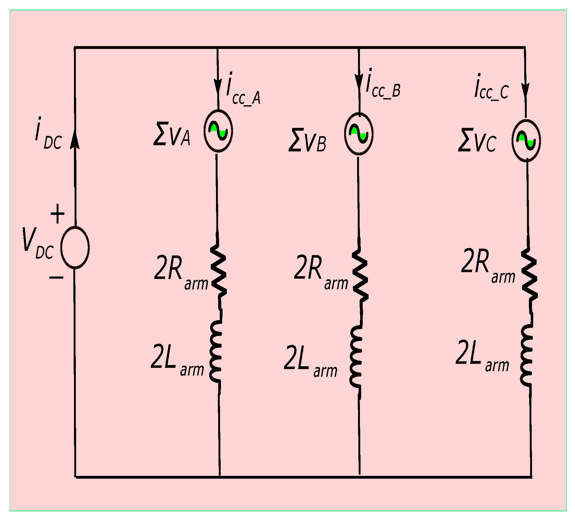
An active power transform is directly responsible for circulating current in the modular multilevel converter. The transformation of energy from the AC side of the modular multilevel converter to its DC side reflects with DC circulating current. There is some low-frequency fluctuation in the submodule voltage because of the floating nature of the submodule’s capacitor. This fluctuation appears at the end, at the arm voltage in the form of dominated second harmonic voltage. Circulating current in between the phases of modular multilevel converter distorts the arm currents, increases the peak value of arm currents, and increases system power losses.
The equivalent circuit of the MMC for circulating current analysis is shown in Figure 11. The dynamics for circulating current can be described by the following equation:
The above equation implies that are only variables for controlling the circulating current in the arm of MMC. Splitting into DC-link voltage and circulating current,
Time domain dynamics for three-phase MMC is as follows:
Circulating currents are formalized in Equations (43)–(45) below. Three-phase circulating currents consist of negative-sequence double-line frequency component.
To control the second harmonic circulating current, DC terms are neglected in the analysis.
Control of the second harmonic current can be accomplished by utilizing a vector method. In a dq rotating frame, the current is controlled with 2 due to its negative-sequence double-line frequency component. The equations for , , and are transformed into -frame by rotating vectors:
Converting -frame to dq-frame, we have
4.5. Description of Outer Loop Controllers of Proposed System
The principal objective of this research work is to operate back-to-back MMC in islanded mode continuously with satisfactory power quality conditions. In the proposed system, the MMC-rectifier controls the DC voltage and AC voltage, whereas the MMC-inverter controls AC voltage and active power.
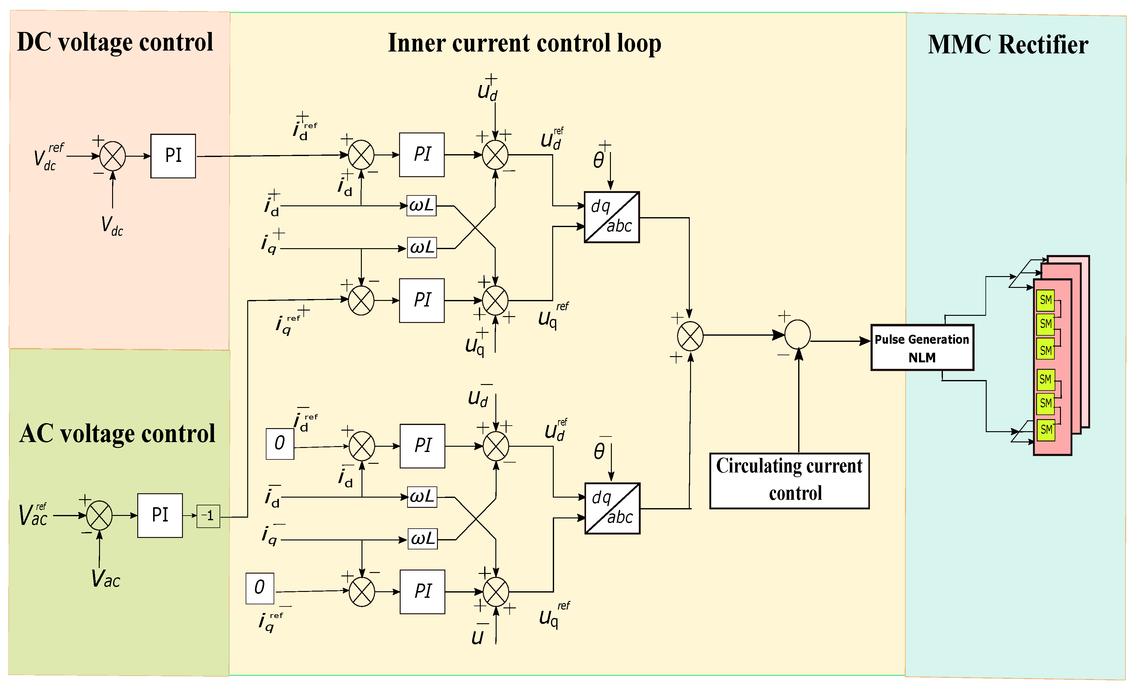
The inner current controller is designed in a dual synchronous reference frame (DSRF) to allow negative-sequence current injection to upstream AC grid and nonlinear load system under unbalanced fault conditions. DC voltage outer control loop is designed for the MMC-rectifier to control the DC voltage, as shown in Figure 13.
This is achieved by creating a d-axis reference current for the inner current loop (ICL), comparing reference DC voltage to DC voltage measured, with an error signal feeding the PI controller. Output reference is fed to the inner current control loop.
The control loop can be represented by the following equation:
The PI controller is tuned at = 8 and = 150. Simulation results for DC voltage and power control of the MMC-rectifier is shown in Figure 14. Outer loop AC voltage controller for both the MMC-rectifier and the MMC-inverter are shown in Figure 13 and Figure 15. The main objective of this control is the shaping of AC voltage. It is carried out by creating a d-axis reference current for the inner current loop (ICL), comparing reference AC voltage to AC voltage measured, with an error signal iq feeding PI controller. Output reference is used for the inner current control loop. The control loop can be represented by the following equation:
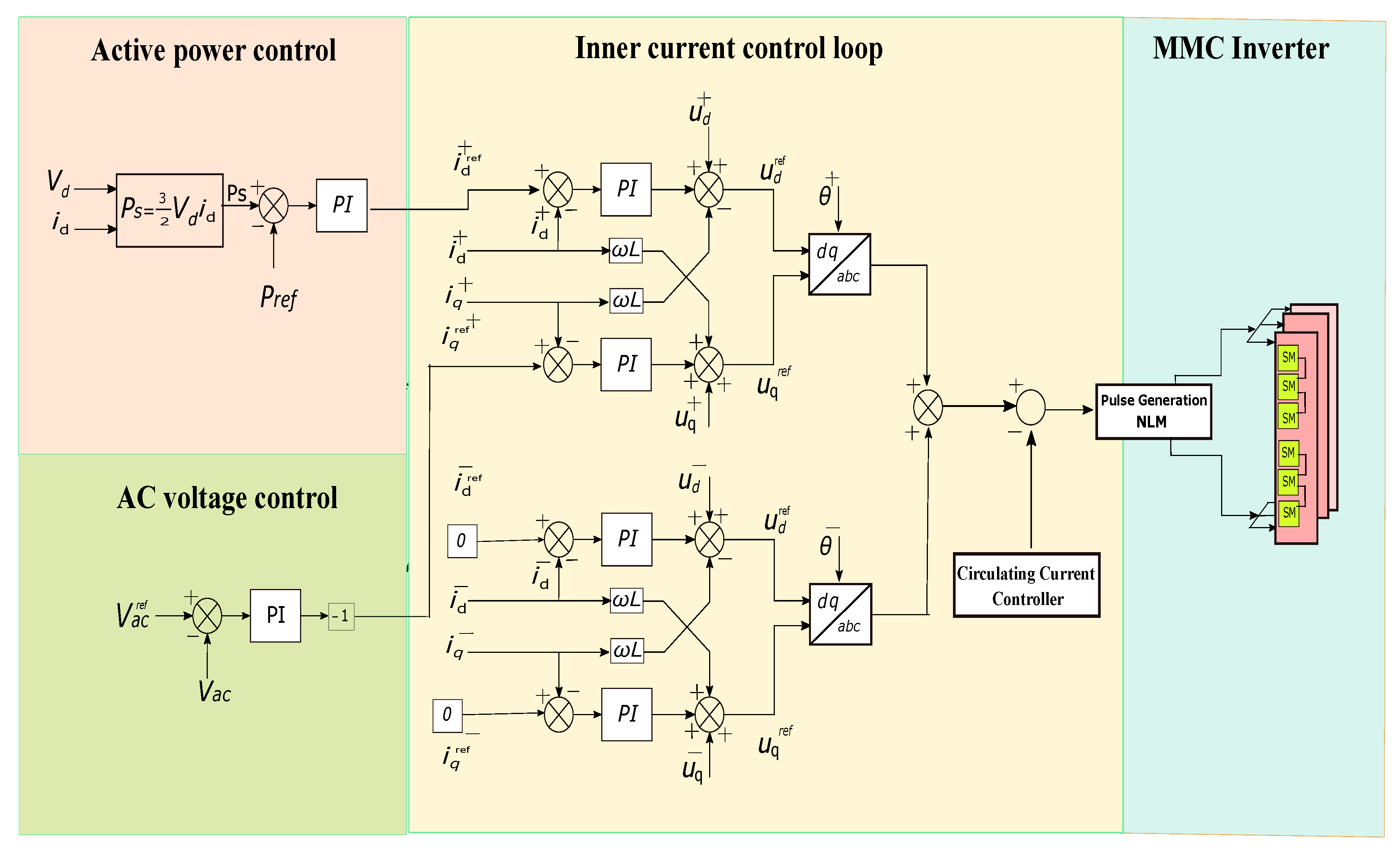
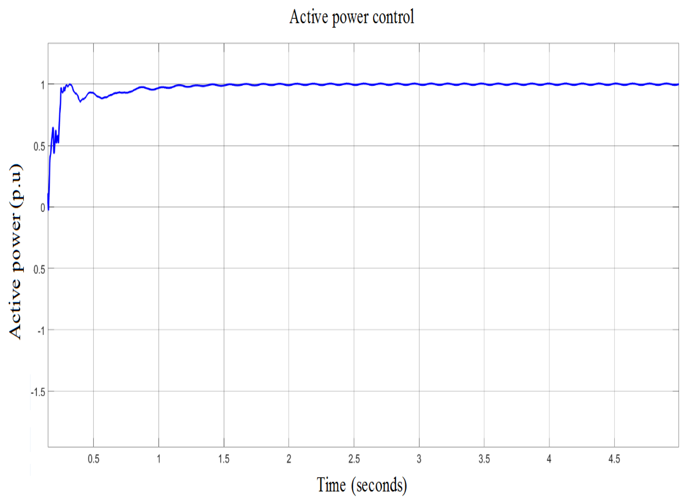
The PI controller is tuned at = 2 and = 260. Outer loop active power controller is designed for the MMC-inverter shown in Figure 15. The output reference is used for inner current control loop. The control loop can be represented by the following equation:
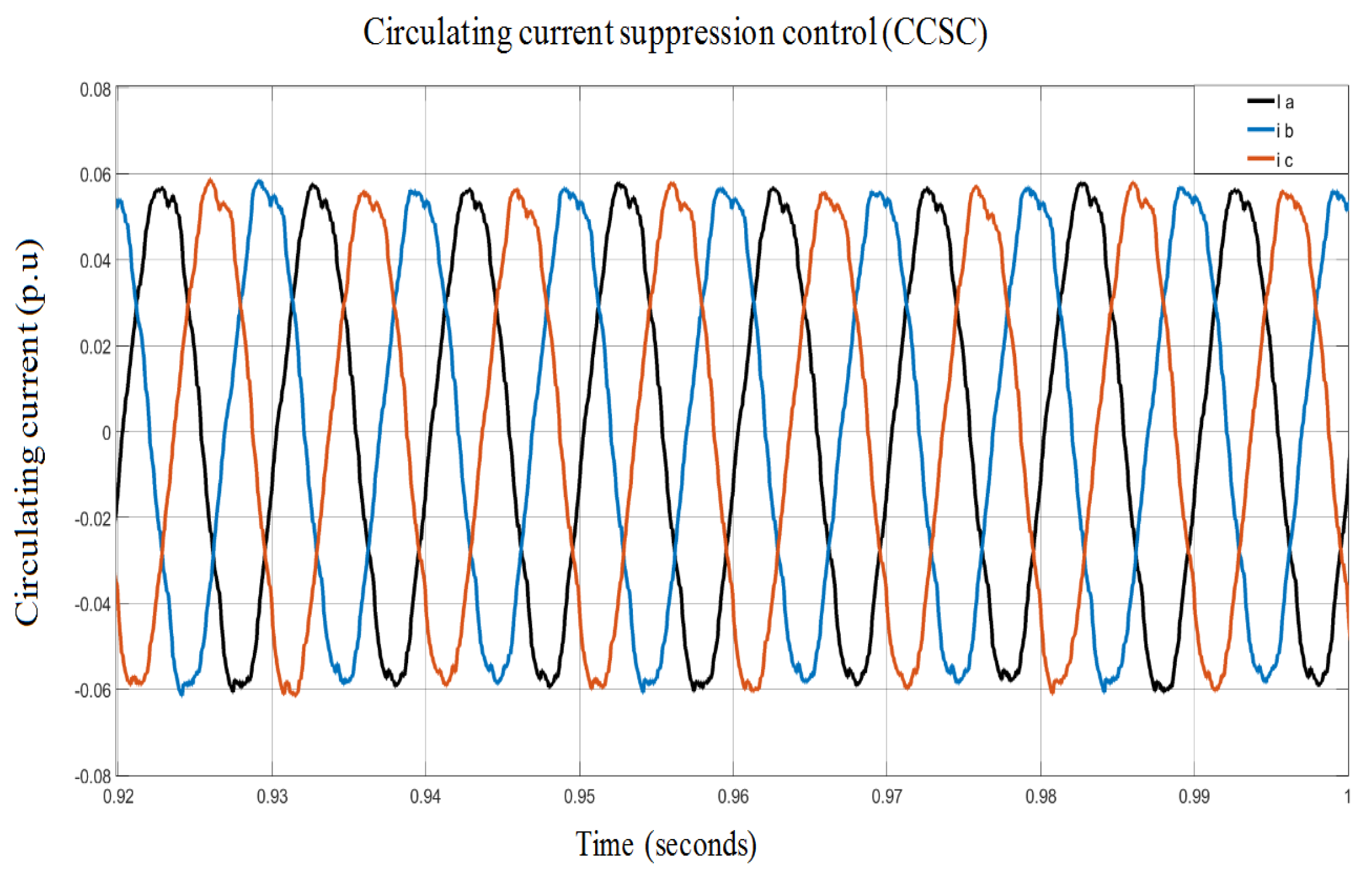
The PI controller is tuned at = 0.1193 and = 55.891 to control the AC side active power of MMC-inverter. Simulation results for active power control of MMC-inverter are shown in Figure 16. This shows that the load is receiving healthy nominal power. Circulating current suppression control is an outer loop control that effectively suppresses the problematic AC component of circulating differential current in modular multilevel converter arms. The controller designed for circulating current suppression control of the MMC-rectifier and the MMC-inverter is the same as that shown in Figure 12. The circulating current controller feeds its reference signals to the inner current loop (ICL). The PI controller is tuned at = 1 and = 5. A simulation for the circulating current suppression controller is shown in Figure 17.
4.6. Modulation Strategy
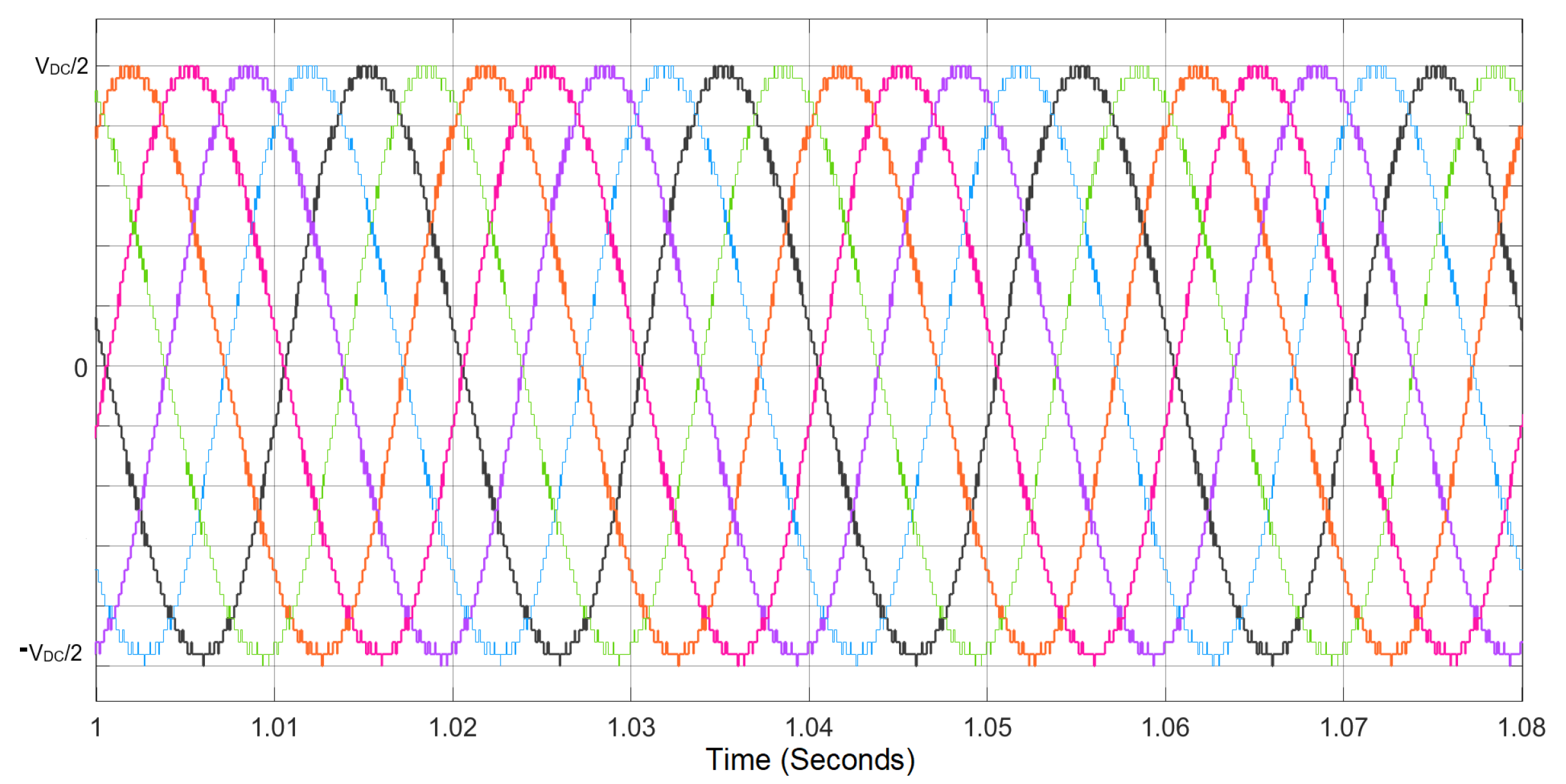
The modulation strategy adopted for the MMC-rectifier and the MMC-inverter is the nearest level modulation technique. This modulation technique allows for the operation of the switching frequency equal to fundamental frequency, reducing the associated conduction losses of the converter effectively. It works by translating the modulating signal into discrete stair waveform, directing the pulse generator how many modules to insert. It is therefore adopted for the system because it is the most common modulation strategy for high-power modular multilevel converter applications. Figure 18 shows the NLM-generated reference signals for MMC. The y-axis shows the number of SMs and x-axis is the time in seconds.
5. Results of the Simulation and Discussion
The simulation for the proposed scheme is conducted in a MATLAB-based Simulink system. The simulation environment and system parameters are illustrated in Table 4.
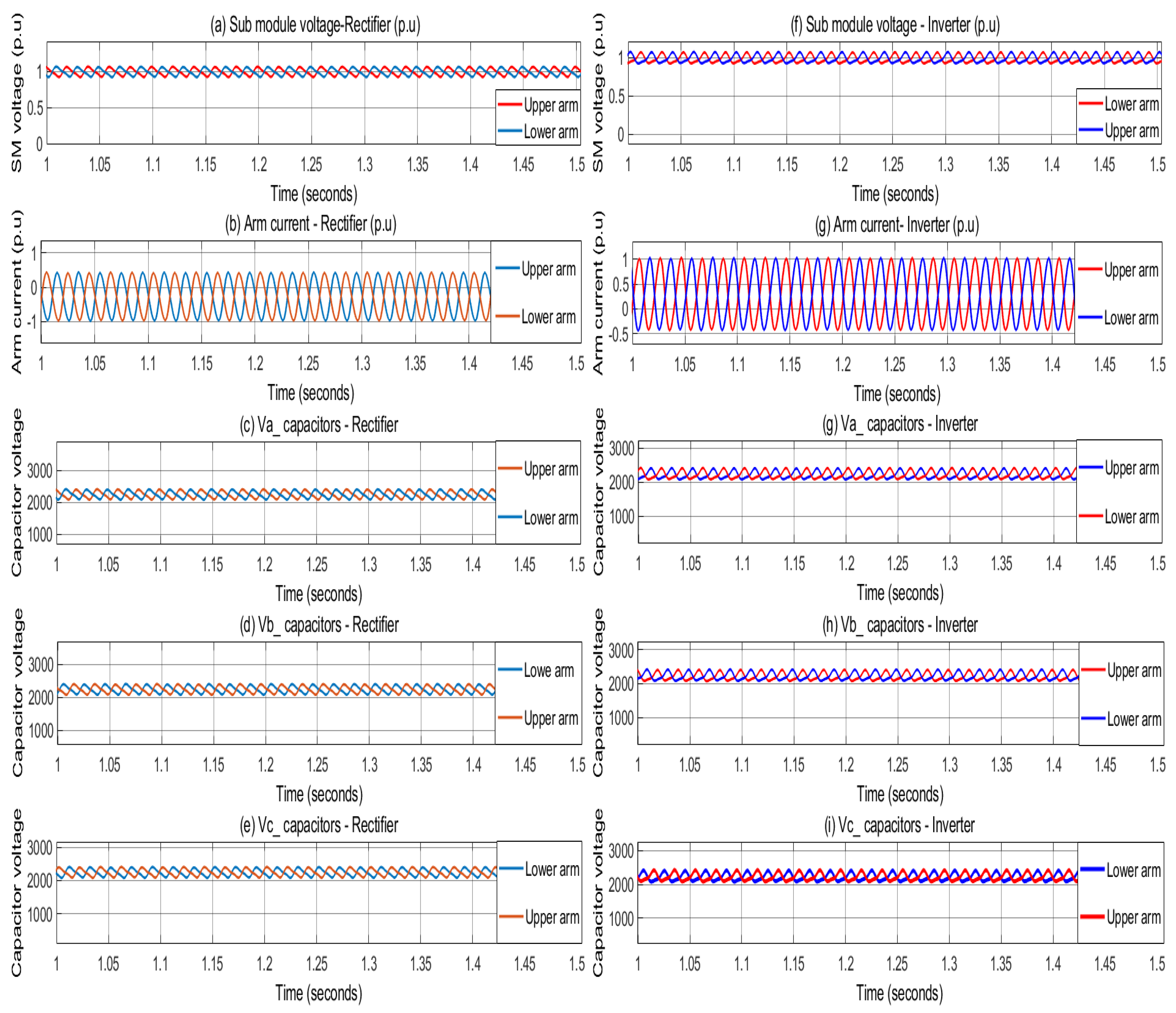
Steady-state operation of both the MMC-rectifier and the MMC-inverter with submodule voltage, arm current, and capacitors voltage is shown in Figure 19.
The voltage of the submodule of MMC is calculated in p.u. where base voltage is set to 2.25 kV, dividing DC voltage by the number of submodules “N”. Figure 19b,g shows that the arm current flows in one phase of each of the MMC-rectifier and MMC-inverter. Arm current is calculated in p.u. as the base current is set as 1.924 kA. Voltage ripple of submodules is approximately 11% which is composed of both AC and DC quantity. Capacitors of submodules can handle this voltage efficiently. IGBT module package of 4.8 kV is used and derated to 2.25 kV having 11% ripples.
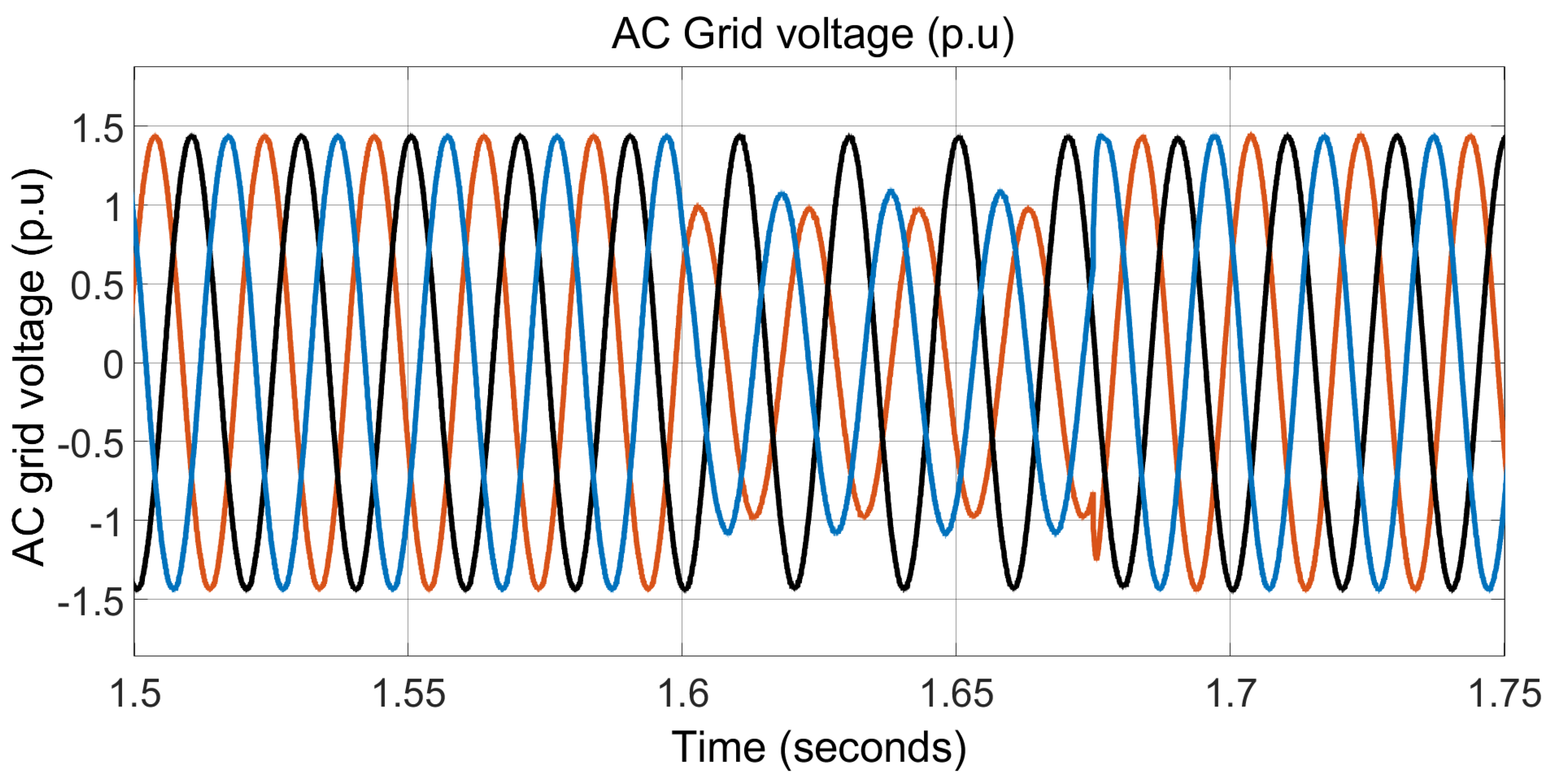
A single-phase voltage sag of up to −60% magnitude, asymmetrical fault, is modeled through the 220 kV source of the system model on the overlaying AC grid side and is the case to be simulated in this research article. A single-phase fault is applied to the simulation model, as shown in Figure 20. When the simulation time is 1.6 s, the effect of the voltage sag is −60% magnitude for 75 ms. AC grid with voltage sag of −60% magnitude feeds the MMC-rectifier.
Voltage Sag Mitigation Strategy
The main objective of this research is to explore the feasibility and potential of the MMC to mitigate voltage sag that is on the overlaying grid due to asymmetrical fault and to deliver a constant power to load distribution. During severe asymmetrical fault conditions, e.g., single-phase fault, in the overlaying grid, voltage sag is for up to −60% within 75 ms, the MMC should provide support to ensure the constant power flow for load distribution. This can be realized by supplying energy from integrated energy in the submodules of the MMC-rectifier and the MMC-inverter to compensate for the missing energy of overlaying grid due to asymmetrical fault.
Energy Storage of Converter
The capacitor of the submodule acts as an energy buffer. Energy stored in the capacitor of the submodule is given by the following equation:
The capacitance of the capacitor is 10.48 mF and the submodule’s voltage is 2.25 kV. The installed energy of a submodule as per the above equation is 26.53 kJ. Energy stored in one arm and phase leg of the converter is 1.591 MJ and 3.18 MJ, respectively. The installed energy of the three-phase MMC converter with 60 submodules is 9.5 MJ. Energy stored in back-to-back MMC is 19 MJ.
During asymmetrical fault in the overlaying grid side, the capacitor of submodules should safely discharge its stored energy to compensate for energy loss made by voltage sag during asymmetrical fault. The modulation index of the MMC is 0.8, and the threshold of capacitor discharging is decided by the steady-state modulation index of MMC. Therefore, the MMC-rectifier allows for DC voltage drop from 1.0 p.u. to 0.8 p.u. without affecting its operation. During the fault conditions, the internal energy storage of the MMC-rectifier and the MMC-inverter should have supplied 10.4% and 12.4% of its installed energy, respectively, as their energy is discharged to approximately 0.896 p.u. and 0.876 p.u. The instantaneous energy of the MMC-rectifier and the MMC-inverter is shown in Figure 21.
Energy stored in the MMC-rectifier is discharged to approximately 0.896 p.u. to compensate for the energy loss caused by voltage sag in the upstream AC grid. The installed energy of the MMC-rectifier is 9.5 MJ. Only 10.4% of installed energy, 0.99 MJ, is discharged to compensate for the effect of the transient voltage sag without affecting the operation of the MMC-rectifier.
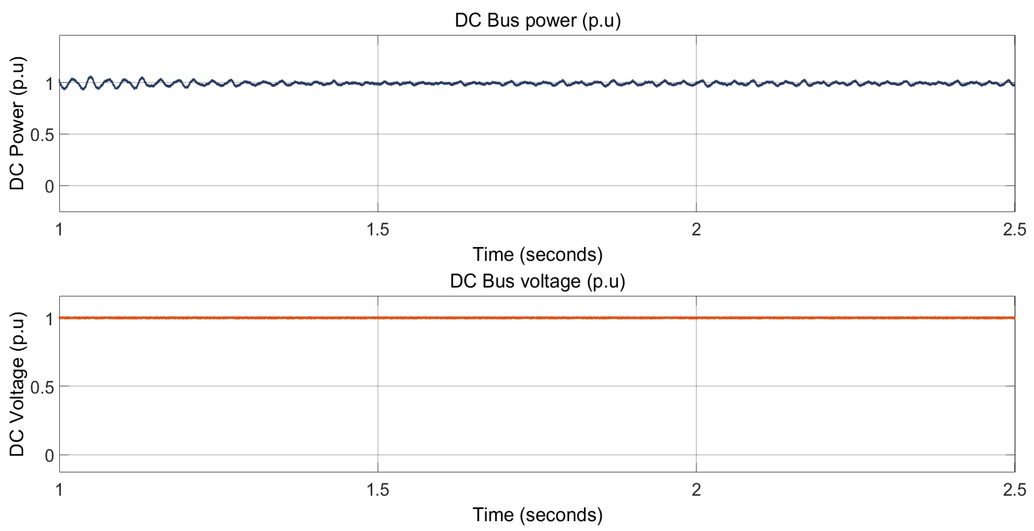
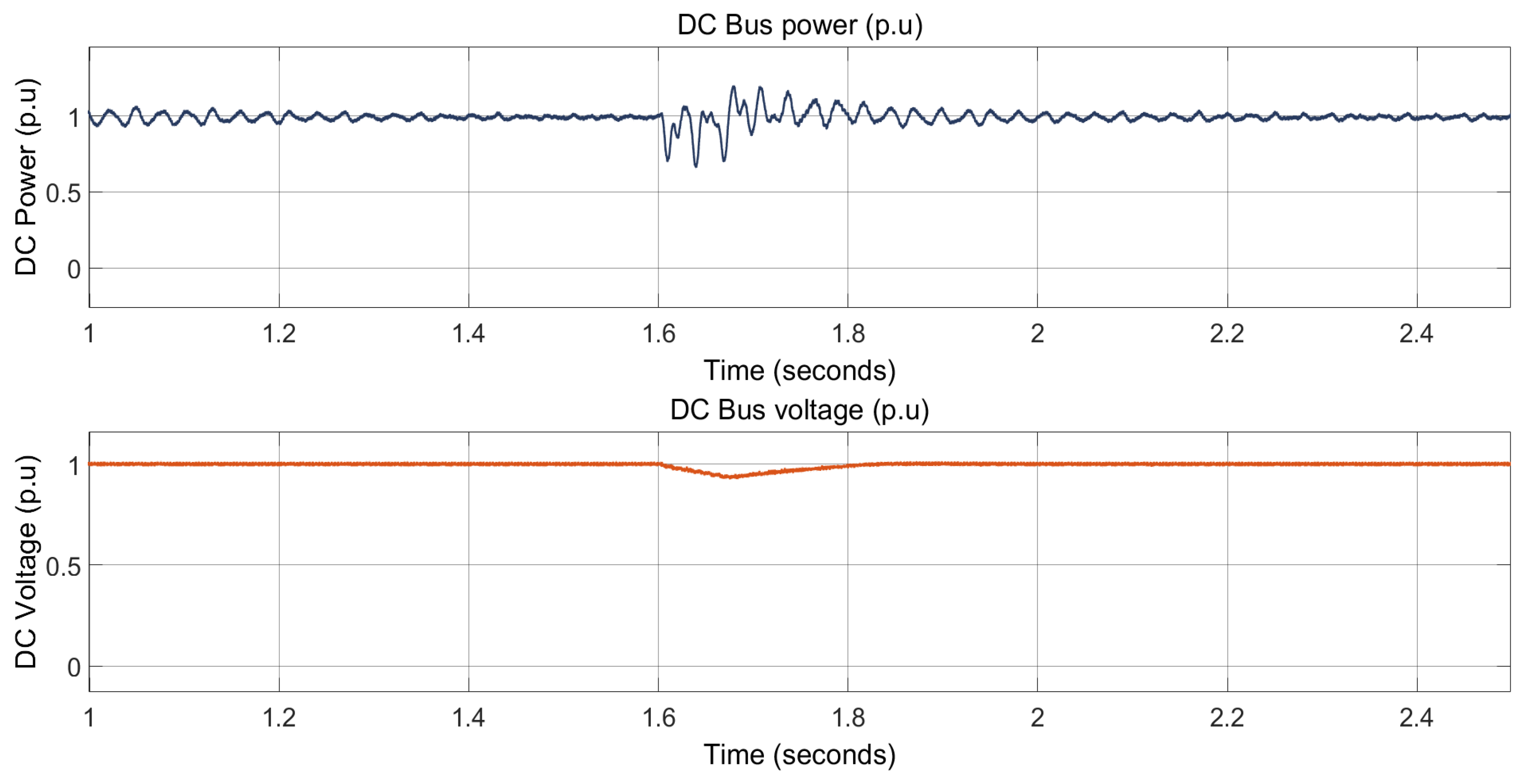
The output DC power of the MMC-rectifier becomes oscillating, as seen in Figure 22, because of the energy interaction between the MMC-rectifier and the MMC-inverter. It can be seen that the DC power peak has reached 1.18 p.u., since it is not harmful, because the DC power equally flows in the upper and lower arms of the both the MMC-rectifier and the MMC-inverter. In this scenario, IGBT bears safely the overcurrent, which is around 25%, that lasts for a one-half cycle.
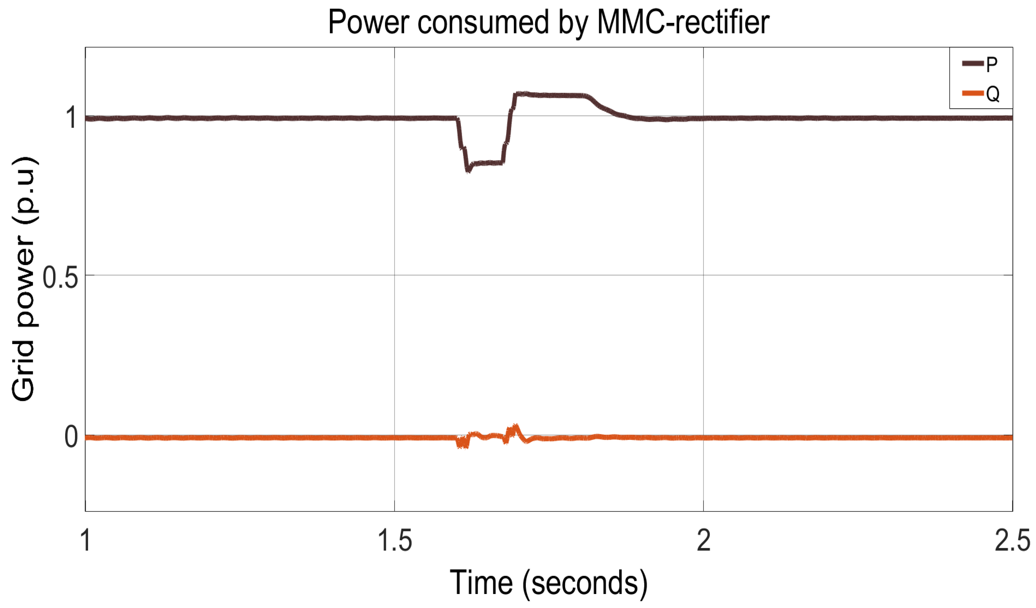
The power consumed by the MMC-rectifier is shown in Figure 23. This shows that when −60% voltage sag is present, active power drawn is reduced to 0.82 p.u., while only 10.4% of installed energy, 0.99 MJ, is discharged to compensate for the effect of the transient voltage sag without affecting the operation of the MMC-rectifier. The MMC-inverter has compensated for the remaining oscillations after the MMC-rectifier using its integrated energy of the submodules.
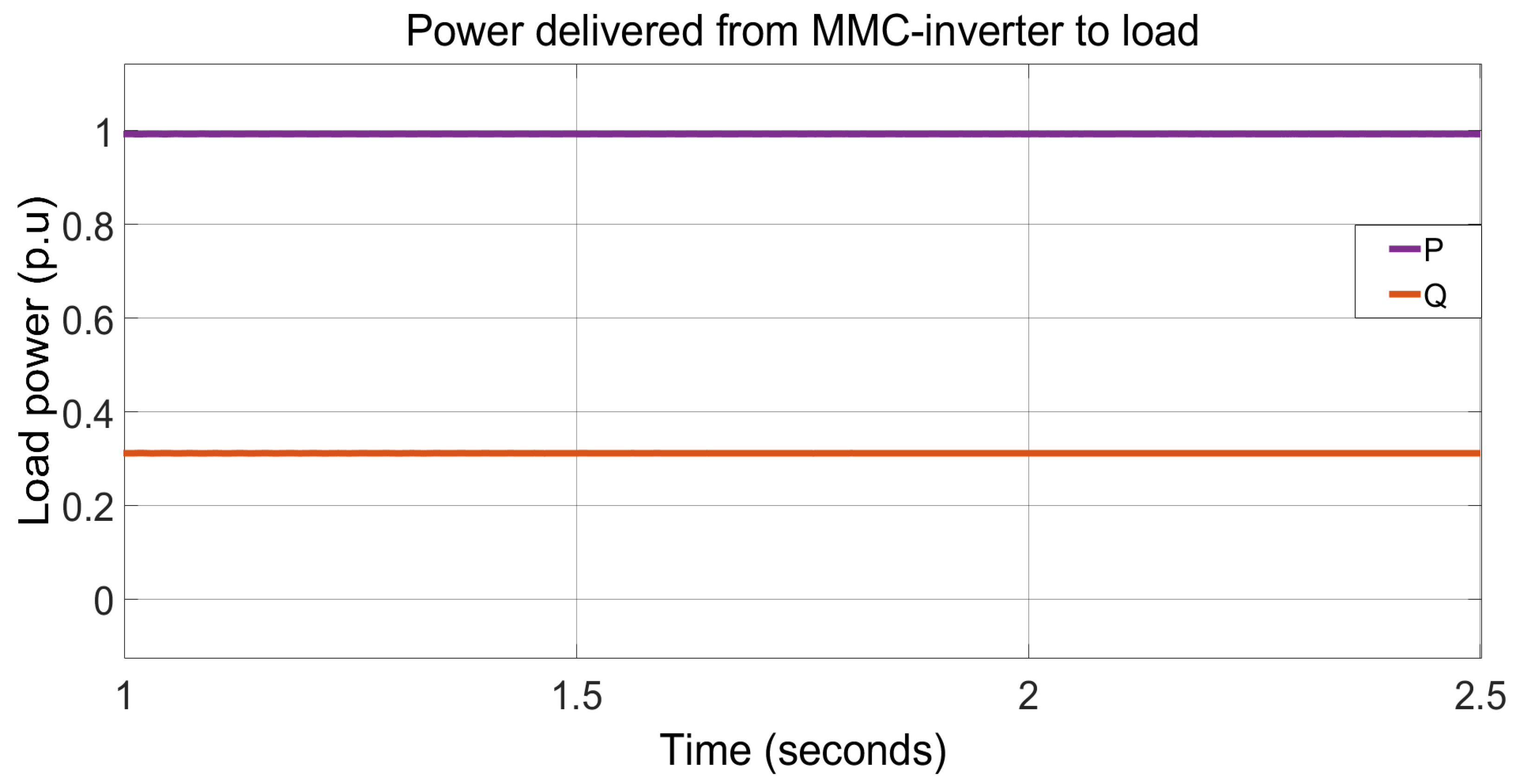
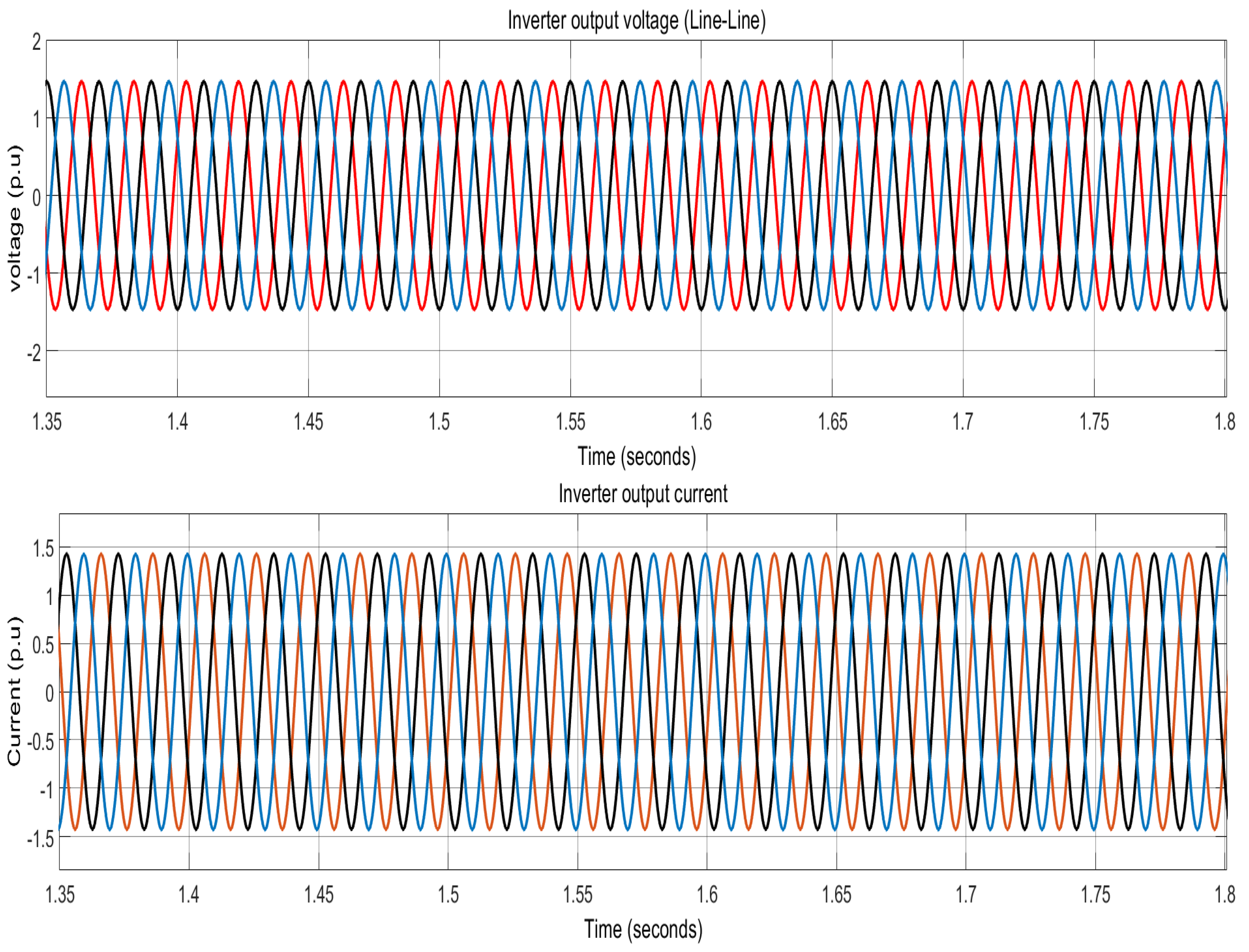
The installed energy of the MMC-inverter is 9.5 MJ. Only 12.4% of installed energy, 1.178 MJ, is discharged for mitigation of the transient voltage sag completely. Figure 24 shows the power delivered from MMC-inverter to the dynamic load distribution. This shows that the load distribution system is healthy and receives AC voltage at a nominal value. These results confirm that the MMC is feasible for an option to mitigate voltage sag and to ensure satisfactory power delivery to the dynamic load distribution. In Figure 25, the output voltage and current of MMC-inverter are normal and healthy with no evidence of voltage sag or energy loss.
It is concluded from Figure 24 and Figure 25 that transient voltage sag of about −60% for the period of 75 ms, the worst sag scenario, in upstream AC grid side is controlled effectively by back-to-back MMC-rectifier and MMC-inverter.
Table 5 shows the comparison of the commonly employed and proposed control strategies for voltage sag mitigation.
6. Conclusions
In this article, we focus primarily on providing satisfactory power delivery to the load distribution system and meeting nominal power demand under transient voltage sag conditions. A back-to-back modular multilevel converter is designed to mitigate transient voltage sags. Using the internal energy storage of submodules of back-to-back modular multilevel converters, transient voltage sag due to asymmetrical fault with a magnitude of −60% for 75 ms in the upstream AC grid is mitigated effectively. The ability of the improved voltage sag mitigation method is proved through simulation results studies. Furthermore, effective control strategies are developed for inner current control (ICC) in the dual synchronous reference frame (DSRF) to control undesirable components, i.e., double-line positive- and negative-sequence components of the circulating current. The effectiveness and performance of the proposed method are well-validated by the results of the simulation.
Future Work and Limitations
Based on this research work, future studies can explore the following aspects:
- An investigation into AC grid stabilization and reactive power injection into upstream AC grid with the back-to-back MMCs.
- Fault handling and detection studies for internal submodules of MMC. Examining and simulating internal submodule faults and detection methods, as well as exploring arm–arm short circuits in the converter.
- Techno-economical studies and reliability analysis of the back-to-back modular multilevel converters.
The limitation of this research scheme is as follows:
- Short circuits in the individual module, as well as flash-over faults between two arms (between the converter arms), cannot be simulated using this model, since the aggregated modeling strategy is used, which considers only the entire converter arm.
Author Contributions
Conceptualization, F.M. and H.R.; methodology, F.M.; formal analysis, F.M.; investigation, H.R.; writing—review and editing, I.A., R.A. and A.B.; supervision, H.R., I.A., R.A. and A.B.; funding acquisition, I.A., R.A. and A.B. All authors have read and agreed to the published version of the manuscript.
Funding
This research was funded by Taif University researchers supporting Project (number TURSP-2020/36), Taif University, Taif, Saudi Arabia.This research work was also partially supported by the faculty of computer science and information technology, University of Malaya, under postgraduate research grant PG035-2016A.
Institutional Review Board Statement
Not applicable.
Informed Consent Statement
Not applicable.
Acknowledgments
The authors are grateful to the Taif University researchers supporting Project (number TURSP-2020/36), Taif University, Taif, Saudi Arabia.This research work was also partially supported by the faculty of computer science and information technology, University of Malaya, under postgraduate research grant PG035-2016A.
Conflicts of Interest
The authors declare no conflict of interest.
References
- Ye, X.; Liu, H.; Hao, S.; Zhang, K.; Lü, G. Comprehensive mitigation strategy of voltage sag based on sensitive load clustering. Int. Trans. Electr. Energy Syst. 2021, 31, e12914. [Google Scholar] [CrossRef]
- Huang, A.; Xiao, X.; Wang, Y. Evaluation Scheme of Voltage Sag Immunity in Sensitive Industrial Process. IEEE Access 2021, 9, 66398–66407. [Google Scholar] [CrossRef]
- Al-Shetwi, A.Q.; Hannan, M.; Jern, K.P.; Mansur, M.; Mahlia, T. Grid-connected renewable energy sources: Review of the recent integration requirements and control methods. J. Clean. Prod. 2020, 253, 119831. [Google Scholar] [CrossRef]
- Alkahtani, A.A.; Alfalahi, S.T.; Athamneh, A.A.; Al-Shetwi, A.Q.; Mansor, M.B.; Hannan, M.; Agelidis, V.G. Power quality in microgrids including supraharmonics: Issues, standards, and mitigations. IEEE Access 2020, 8, 127104–127122. [Google Scholar] [CrossRef]
- Srivatchan, N.; Rangarajan, P. Half cycle discrete transformation for voltage sag improvement in an islanded microgrid using dynamic voltage restorer. Int. J. Power Electron. Drive Syst. 2018, 9, 25–32. [Google Scholar] [CrossRef]
- Fardad, N.; Soleymani, S.; Faghihi, F. Voltage Sag Investigation of Microgrid in the presence of SMES and SVC. Signal Process. Renew. Energy 2019, 3, 23–34. [Google Scholar]
- Kumar, A.S.; Rajasekar, S.; Raj, P.A.D.V. Power quality profile enhancement of utility connected microgrid system using ANFIS-UPQC. Procedia Technol. 2015, 21, 112–119. [Google Scholar] [CrossRef] [Green Version]
- Farsadi, M.; Shahrak, A.G.; Tabrizi, S.D. DVR with fuzzy logic controller and photovoltaic for improving the operation of wind farm. In Proceedings of the 2013 8th International Conference on Electrical and Electronics Engineering (ELECO), Bursa, Turkey, 28–30 November 2013; pp. 191–195. [Google Scholar]
- Omar, R.; Rahim, N.; Sulaiman, M. Dynamic voltage restorer application for power quality improvement in electrical distribution system: An overview. Aust. J. Basic Appl. Sci. 2011, 5, 379–396. [Google Scholar]
- He, J.; Liang, B.; Li, Y.W.; Wang, C. Simultaneous microgrid voltage and current harmonics compensation using coordinated control of dual-interfacing converters. IEEE Trans. Power Electron. 2016, 32, 2647–2660. [Google Scholar] [CrossRef]
- Al-Shetwi, A.Q.; Hannan, M.; Jern, K.P.; Alkahtani, A.A.; PG Abas, A. Power quality assessment of grid-connected PV system in compliance with the recent integration requirements. Electronics 2020, 9, 366. [Google Scholar] [CrossRef] [Green Version]
- Molinas, M.; Suul, J.A.; Undeland, T. Low voltage ride through of wind farms with cage generators: STATCOM versus SVC. IEEE Trans. Power Electron. 2008, 23, 1104–1117. [Google Scholar] [CrossRef]
- Khadem, S.K.; Basu, M.; Conlon, M.F. Integration of UPQC for Power Quality improvement in distributed generation network-a review. In Proceedings of the 2020 2nd IEEE PES International Conference and Exhibition on Innovative Smart Grid Technologies, Delft, The Netherlands, 26–28 October 2020; pp. 1–5. [Google Scholar]
- Rasheed, A.; Rao, G.K. Improvement of power quality for microgrid using fuzzy based UPQC controller. Indian J. Sci. Technol. 2020, 8, 1. [Google Scholar]
- Gayatri, M.; Parimi, A.M.; Kumar, A.P. Utilization of Unified Power Quality Conditioner for voltage sag/swell mitigation in microgrid. In Proceedings of the 2016 Biennial International Conference on Power and Energy Systems: Towards Sustainable Energy (PESTSE), Bengaluru, India, 21–23 January 2016; pp. 1–6. [Google Scholar]
- Hoseinnia, S.; Akhbari, M.; Hamzeh, M.; Guerrero, J. A control scheme for voltage unbalance compensation in an islanded microgrid. Electr. Power Syst. Res. 2019, 177, 106016. [Google Scholar] [CrossRef]
- Marquardt, R. Stromrichterschaltung mit Verteilten Energiespeichern und Verfahren zur Steuerung Einer Derartigen Stromrichterschaltung. German Patent DE10,103,031, 24 January 2001. [Google Scholar]
- Ji, M.; Wang, Y.; Tan, K.; Wang, C. A voltage-balanced hybrid MMC topology for DC fault ride-through. In Proceedings of the 2019 IEEE Innovative Smart Grid Technologies-Asia (ISGT Asia), Chengdu, China, 21–24 May 2019; pp. 2282–2286. [Google Scholar]
- Mahmoud, A.A.; Hafez, A.A.; Yousef, A.M. Modular multilevel converters for renewable energies interfacing: Comparative review. In Proceedings of the 2019 IEEE Conference on Power Electronics and Renewable Energy (CPERE), Aswan, Egypt, 23–25 October 2019; pp. 397–406. [Google Scholar]
- Pereira, H.A.; Mendes, V.F.; Harnefors, L.; Teodorescu, R. Comparison of 2L-VSC and MMC-based HVDC Converters: Grid Frequency Support Considering Reduced Wind Power Plants Models. Electr. Power Compon. Syst. 2020, 45, 2007–2016. [Google Scholar] [CrossRef]
- Franquelo, L.G.; Rodriguez, J.; Leon, J.I.; Kouro, S.; Portillo, R.; Prats, M.A. The age of multilevel converters arrives. IEEE Ind. Electron. Mag. 2018, 2, 28–39. [Google Scholar] [CrossRef] [Green Version]
- Rohner, S.; Hiller, M.; Sommer, R. A new highly modular medium voltage converter topology for industrial drive application. In Proceedings of the Power Electronics and Applications, EPE 13th European Conference, Barcelona, Spain, 8–9 September 2009. [Google Scholar]
- Saeedifard, M.; Iravani, R. Dynamic performance of a modular multilevel back-to-back HVDC system. IEEE Trans. Power Deliv. 2010, 25, 2903–2912. [Google Scholar] [CrossRef]
- Tu, Q.; Xu, Z.; Xu, L. Reduced switching-frequency modulation and circulating current suppression for modular multilevel converters. IEEE Trans. Power Deliv. 2011, 26, 2009–2017. [Google Scholar]
- Jacobson, B.; Karlsson, P.; Asplund, G.; Harnefors, L.; Jonsson, T. VSC-HVDC transmission with cascaded two-level converters. In Cigré Session; Cigre: Paris, France, 2010; pp. B4–B110. [Google Scholar]
- Ilves, K.; Antonopoulos, A.; Norrga, S.; Nee, H.P. Steady-state analysis of interaction between harmonic components of arm and line quantities of modular multilevel converters. IEEE Trans. Power Electron. 2011, 27, 57–68. [Google Scholar] [CrossRef]
- Sharifabadi, K.; Harnefors, L.; Nee, H.P.; Norrga, S.; Teodorescu, R. Design, Control, and Application of Modular Multilevel Converters for HVDC Transmission Systems; John Wiley & Sons: Hoboken, NJ, USA, 2016. [Google Scholar]
- Allebrod, S.; Hamerski, R.; Marquardt, R. New transformerless, scalable modular multilevel converters for HVDC-transmission. In Proceedings of the 2008 IEEE Power Electronics Specialists Conference, Rhodes, Greece, 15–19 June 2008; pp. 174–179. [Google Scholar]
- Chhor, J.; Sourkounis, C. Optimal voltage control strategy for grid-feeding power converters in AC microgrids. Electr. Power Syst. Res. 2019, 176, 105945. [Google Scholar] [CrossRef]
Figure 1.
Dynamic voltage restorer–integrated AC grid system to mitigate voltage sag.

Figure 2.
Typical configuration of SVC used for mitigation of voltage sag in AC grid system.

Figure 3.
General configuration of UPQC for voltage sag mitigation in AC grid system.

Figure 4.
Component design flow chart of modular multilevel converter.

Figure 5.
Submodule of MMC.

Figure 6.
A detailed control system model of the MMC-rectifier and the MMC-inverter.

Figure 7.
Equivalent circuit of MMC.

Figure 8.
MMC inner current control loop.

Figure 9.
Control system.

Figure 10.
MMC DSRF inner current control loop.

Figure 11.
Equivalent circuit of the MMC for circulating current.

Figure 12.
Circulating current controller of the converter.

Figure 13.
Outer and inner control loop for the MMC-rectifier.

Figure 14.
DC voltage control of the MMC-rectifier.

Figure 15.
Outer and inner control loop for MMC-inverter.

Figure 16.
Active power control of inverter.

Figure 17.
Circulating current suppression control of the MMC-rectifier.

Figure 18.
Nearest level modulation signals for MMC.

Figure 19.
Steady state operation of the MMC-rectifier and the MMC-inverter with SMs voltage, current, and capacitors voltage.
Figure 19.
Steady state operation of the MMC-rectifier and the MMC-inverter with SMs voltage, current, and capacitors voltage.

Figure 20.
Upstream AC grid voltage sag of −60% magnitude.

Figure 21.
Instantaneous energy in the MMC-rectifier and the MMC-inverter.

Figure 22.
DC bus power.

Figure 23.
Power drawn from grid to feed rectifier.

Figure 24.
Power delivered from MMC-inverter to load distribution system.

Figure 25.
Inverter output voltage and current.


Table 1.
The voltage drop and time duration allowed differently based on grid codes in different countries.
Table 1.
The voltage drop and time duration allowed differently based on grid codes in different countries.
| S. No | Country | Voltage Drop | Time |
|---|---|---|---|
| 1 | USA | 15% | 0.6 s |
| 2 | UK | 15% | 0.14 s |
| 3 | China | 20% | 0.625 s |
| 4 | Italy | 0% | 0.2 s |
| 5 | Japan | 15% | 1.0 s |
| 6 | Germany | 0% | 0.15 s |
| 7 | South Africa | 0% | 0.15 s |
| 8 | Spain | 0% | 1.5 s |
| 9 | Australia | 15% | 0.45 s |
| 10 | Denmark | 20% | 0.5 s |
Table 2.
Comparison of various technologies used for voltage sag mitigation.
| Factors | DVR | SVC | UQPC |
|---|---|---|---|
| Rating | High rating | Low rating | High rating |
| Speed of operation | Fast | Less than DVR | Faster |
| Compensation method | Series compensation | Shunt compensation | Both series and shunt |
| Active & Reactive power | Reactive/active | Reactive | Both active and reactive |
| Harmonics | Much less | Less | Least |
| Problem addressed | Voltage sag/Swell | Voltage sag/Swell | Sag/Swell/Transients |
| Complexity | High | High | Higher |
| Cost | High | High | Higher |
Table 3.
Market availability of high-voltage IGBT modules.
| Blocking Voltage | Current Rating (Ampere) | ||||
|---|---|---|---|---|---|
| 1.7 kV | 1000 | 1200 | 1600 | 3600 | - |
| 3.3 kV | 450 | 600 | 800 | 1200 | - |
| 4.5 kV | 900 | 1000 | 1350 | 1500 | - |
| 6.5 kV | 225 | 300 | 600 | 900 | 1000 |
Table 4.
Parameters of upstream AC, DC grid and modular multilevel converter.
| S. No | Parameter | Values |
|---|---|---|
| 1 | Upstream AC grid voltage | 220 kV |
| 2 | Transformer rating/AC grid side | 220/66 kV (Core type) |
| 3 | No of SMs in MMC | 60 |
| 4 | Arm inductance | 0.0164 (p.u.) |
| 5 | Arm resistance | 0.0300 (p.u.) |
| 6 | Submodule capacitance | 0.0105 (p.u.) |
| 7 | DC grid voltage | 135 kV |
| 8 | AC grid voltage | 66 kV |
| 9 | Transformer rating/load side | 66/11 kV (Core type) |
| 10 | Dynamic load active power | 10 MW |
| 11 | Dynamic load reactive power | 25 MVAR |
| 12 | Sampling time | 20 μs |
Table 5.
Comparison of the commonly employed and proposed control strategies for voltage sag mitigation.
Table 5.
Comparison of the commonly employed and proposed control strategies for voltage sag mitigation.
| Method | Issue Mitigated | Outcomes | Limitations | Reference |
|---|---|---|---|---|
| DVR | Voltage sag | -Voltage sag is mitigated during different types of grid faults. | -High cost. -Quite complex. | [5] |
| Fuzzy logic controller-based DVR | Voltage sag | -Mitigated voltage sag up to 50%. -Rapid detection rate compared to conventional methods. | -All types of sags are not tested. -Frequency fluctuation. | [8] |
| SVC | Voltage sag | -Voltage sag of all kinds addressed. -During sag events, inject reactive power to maintain voltage. | -Lower performance than DVR. | [6] |
| Adapted SVC control strategy | Voltage sag | -Voltage sag is addressed with reactive current injection. -Voltage stability is fully supported during faults scenario. | -No grid code standards are followed. | [29] |
| ANFIS-Based UPQC | Voltage sag | -Voltage sag is addressed with reactive current injection. -Support voltage stability during faults. | -Increased cost. -High complexity. | [7] |
| MMC-based voltage sag mitigation (Proposed method) | Voltage sag | -Compensate for missing energy of upstream AC grid due to fault using integrated energy in the SMs of MMC. -Mitigated voltage sag up to 60%. -Response time is very fast (<1 ms). -Support voltage stability during faults.-Simple design and control mechanism. -It has high redundancy possibilities. -It has smaller footprint. -Low cost (no need of custom PQ regulator). -Low harmonics and low conduction power losses. | -When a semiconductor fails in a sub-module, there is a need for protection. The capacitor will release stored energy causing an explosion. | Proposed in this research. |
Publisher’s Note: MDPI stays neutral with regard to jurisdictional claims in published maps and institutional affiliations. |
© 2022 by the authors. Licensee MDPI, Basel, Switzerland. This article is an open access article distributed under the terms and conditions of the Creative Commons Attribution (CC BY) license (https://creativecommons.org/licenses/by/4.0/).
Share and Cite
MDPI and ACS Style
Muhammad, F.; Rasheed, H.; Ali, I.; Alroobaea, R.; Binmahfoudh, A. Design and Control of Modular Multilevel Converter for Voltage Sag Mitigation. Energies 2022, 15, 1681. https://doi.org/10.3390/en15051681
AMA Style
Muhammad F, Rasheed H, Ali I, Alroobaea R, Binmahfoudh A. Design and Control of Modular Multilevel Converter for Voltage Sag Mitigation. Energies. 2022; 15(5):1681. https://doi.org/10.3390/en15051681
Chicago/Turabian StyleMuhammad, Fazal, Haroon Rasheed, Ihsan Ali, Roobaea Alroobaea, and Ahmed Binmahfoudh. 2022. "Design and Control of Modular Multilevel Converter for Voltage Sag Mitigation" Energies 15, no. 5: 1681. https://doi.org/10.3390/en15051681
Note that from the first issue of 2016, this journal uses article numbers instead of page numbers. See further details here.