
Solid Rotor Core vs. Lamination Rotor Core in Fractional-Slot PMSM Motor with High Power Density


Łukasiewicz Research Network—Institute of Electrical Drives and Machines KOMEL, 40-203 Katowice, Poland
*
Author to whom correspondence should be addressed.
Energies 2022, 15(15), 5729; https://doi.org/10.3390/en15155729
Submission received: 25 July 2022
/
Revised: 4 August 2022
/
Accepted: 5 August 2022
/
Published: 6 August 2022
(This article belongs to the Special Issue Design and Optimization of Fractional Kilowatt or Medium Power Electrical Machines)
Abstract
:Fractional-slot PMSM motors allow for obtaining high values of power density factors, but at the same time, they are characterized by high values of rotor losses—in the rotor core and permanent magnets. The main causes of rotor losses in this type of motor are subharmonics and a high content of higher harmonics in the distribution of the magnetomotive force MMF. The use of a solid rotor core simplifies the construction and technology of the rotor but eddy current losses in the core account for a significant percentage of the total rotor losses. It is well known that a laminated core reduces eddy currents, while for motors with an outer rotor, it complicates the construction and increases weight. Thus, the question arises about the necessity to use a laminated core in a high power density motor and the real benefits of this. The article presents a comparison of the motors with a solid rotor core and a laminated rotor core, considering the value of rotor losses, power density factor, efficiency and the range of rotational speed and range of current load. The analysis was carried out for various types of sheets for laminated core and solid steel and SMC (Soft Magnetic Composite) material for solid rotor core. FEM models were used in the analysis, and the results were partially verified with the results of laboratory tests of motor models. The object of the analysis is a fractional-slot PMSM motor with an external rotor with surface permanent magnets (SPM). Motor weight is about 10 kg, and the maximum power is 50 kW at 4800 rpm.
1. Introduction
Motors with high power density (4 kW/kg and more) are sought in industries such as automotive, aviation or marine, which expect dedicated solutions with a high degree of technical advancement [1,2,3,4,5,6,7,8,9]. For these applications, rotational speeds are usually in the range up to 5000–6000 rpm; therefore, it should be understood that high power density is directly related to obtaining high shaft torque values. Fractional-slot PMSM motors are a particularly interesting solution that allows for obtaining very high operating parameters (torque, power) of the motor and, at the same time, low weight. One of the conditions is to work with high values of the supply frequency (500–1000 Hz), high magnetic flux density in the magnetic circuit elements (1.9–2 T) and high current load (>12 A/mm2). In addition, the proper design of the electromagnetic circuit is very important, including the use of appropriate materials [4,5,6,7,8,9,10,11]. At the same time, fractional slot motors are usually characterized by the content of subharmonics and a high content of higher harmonics in the distribution of the magnetomotive force MMF, which is one of the main causes of eddy current losses in the rotor elements—in the rotor yoke and permanent magnets [12,13,14,15,16,17,18,19,20,21,22]. These losses can demagnetize the permanent magnets or just limit the required operating range of rotational speed or shaft power of the motor. This is, therefore, one of the main issues at the design stage of this type of motor.
There are methods known to limit the value of eddy current losses in rotor elements. The paper [11] presents the issue of the correct selection of the slot-pole combination, which allows the reduction of rotor losses. The articles [23,24,25,26] present methods of reducing eddy current losses in the rotor by segmentation of permanent magnets. Similarly, in the publications [19], the authors present various methods of reducing the negative effect of eddy current losses in the rotor based on the optimization of the shape of selected components of the electromagnetic circuit.
The selection of appropriate materials in the electromagnetic circuit is also important in reducing eddy current losses. In the publications [1,5,7,10], the authors present and describe the properties of a number of different materials used in the electromagnetic circuits of motors with high operating parameters (mainly traction motors), but they do not show or analyze the direct impact of their application on the values of losses in motors with high power density. The material properties of magnetic circuit elements in terms of limiting eddy current losses in the rotor are analyzed in publication [27]. However, they apply to special covers on permanent magnets, copper or other materials, which are not analyzed in this paper. Moreover, the use of this type of shield is intended mainly for high-speed machines, the operating conditions of which differ from those of motors with high power density.
One of the known methods of limiting eddy current losses is laminating the rotor core. The external rotor with surface permanent magnet of the fractional-slot motor can be made as solid or laminated. The solid rotor simplifies the construction of the motor as it does not require additional elements to support the laminated core, but it causes higher values of losses in the rotor core. The laminated rotor core reduces eddy current losses but complicates the technological process and increases the rotor weight. As part of the work, the possibilities of using various types of materials in both the solid rotor and the laminated rotor were considered.
The purpose of this study is to present a comparison of a high power density motor with a solid rotor and a laminated rotor core, considering the value of rotor losses, power density factor, efficiency and the range of rotational speed and range of current load. It should be emphasized here the importance of the analysis carried out in the context of applications in motors with high power density. The authors did not find similar publications linking these issues. These high power density motors operate in conditions incomparable to the operating conditions of other motors, i.e., when supplied with high frequency voltage (approx. 800 Hz), with very high values of magnetic flux density in the stator core and rotor yoke (approx. 1.9–2.2 T) and at very high current loads of 12–15 A/mm2. All these factors significantly affect the value of losses in the rotor elements. It is also worth noting that such operating conditions may cause unfavorable phenomena in the motor, e.g., bearing currents [28]. The authors’ intention is also to assess the possibility of using a solid rotor core in motor operating in such demanding conditions, as well as to assess the real benefits of replacing it with a laminated rotor.
2. Object of the Analysis
The object of the analysis is 20-pole, 24-slots PMSM motor with an external rotor, with surface permanent magnets (SPM) and concentrated winding. Figure 1 shows the cross-section of the fragment of the motor with a solid rotor (Figure 1a) and a laminated rotor (Figure 1b), which are analyzed in this paper. Table 1 presents the basic data for the analyzed motor model. NO27 sheets (0.27 mm) were used in the stator core and permanent magnets N45SH in the rotor. The permissible operating temperature for this type of magnet is 150 °C (catalog value). It was assumed that the motor is powered by a DC source through a sinusoidal AC motor controller. For all analyzed models, a highly efficient water cooling system was assumed, and the permissible rated current density in the winding would be J = 15 A/mm2. The end winding is also flooded with resin with good thermal conductivity. The laminated core rotor requires additional support, so the total motor weight is 11.4 kg, while the solid rotor motor weighs 10.2 kg. These differences were taken into account when determining the power density factor ξ for the analyzed solutions.
The electromagnetic circuit of the motor has been designed taking into account the key guidelines known from the literature [11,12,13,29,30] in the scope of limiting the value of eddy current losses in the rotor. One of them is the correct selection of the number of stator slots Qs to the number of magnetic poles 2p in order to limit the content of subharmonics in the MMF force distribution. These subharmonics cause an increased content of eddy current losses in the rotor elements, and thus also the temperature, which in extreme cases may even lead to demagnetization of permanent magnets.
Figure 2 shows the harmonic distribution of the magnetomotive force MMF for the selected slot-pole combination. The fundamental harmonic is marked in color. The MMF distribution contains only one subharmonic with an amplitude value of about 30% of the fundamental harmonic and a relatively small number of odd higher harmonics.
3. Losses in Rotor Elements
In using the developed calculation model, the total value of losses in the rotor core ΔPTr was calculated as the sum of losses in permanent magnets ΔPPM and losses in the rotor yoke ΔPYr. Magnet losses ΔPPM were calculated as the sum of the losses in individual magnets within one full magnetic symmetry, multiplied by the number of magnetic symmetries.
It is known from the literature [19] that the dominant losses in the solid rotor elements are eddy current losses Pc. In papers [13,14,15,16,17,18], the theory of the eddy current phenomenon induced in the rotor elements is presented. It is known that the eddy current losses strictly depend on the resistivity of the material of a given element. The resistivity of NdFeB permanent magnets is approximately 0.625 MS/m, while the resistivity of the steel used in the solid rotor model is 1.95 MS/m; therefore, the eddy current losses cannot be ignored.
In general, the eddy current losses Pc in the 2D plane on the surface S can be calculated from the equation found in [21]:
The current density in the magnets or rotor yoke is calculated, according to the second of Maxwell’s equation:
where
Considering these relationships, it can be proved that connecting the material parameters with the eddy current losses Pc can be written as [31]:
where
σ—electrical conductivity, b—material thickness, f—frequency, ρ—mass density, E—electric field strength, B—magnetic flux density, T—period.
For laminated core and SMC core, power losses in rotor yoke ΔPYr are equal to the losses ΔPFe, calculated according to expression (6), where Ph—component of hysteresis losses, Pc—component of eddy current losses, Pe—component of excess losses.
where
Kh—hysteresis loss coefficient, Kc—eddy current loss coefficient, Ke—excess loss coefficient.
Eddy current loss coefficient from Formula (8) is calculated as:
4. FEM Analysis
The analysis was performed on the two-dimensional computational model of a motor with the use of the FEM method. Due to this fact, the end effect and segmentation of the permanent magnet were ignored. The ANSYS Electromagnetic and Octave FEMM software was used for simulations. Figure 3 shows the calculated distribution of the flux density from permanent magnets in the elements of the electromagnetic circuit of the motor model. The maximum value of the flux density in the stator teeth is approximately 2.0 T, in the stator yoke, it is 1.65 T, while the maximum value of the flux density in the rotor yoke is 1.8 T.
In order to extend the scope of the analysis, calculations were carried out for several types of materials in the solid core—S355j2 and Somaloy 700 3p, and for several materials in the laminated core—M400-50A, NO27 and Vacoflux48. It should be noted that the changes in individual calculation models concerned only the material properties of the rotor yoke. The geometric dimensions of the electromagnetic circuit and the rest of the data were the same in all models. The distribution of the magnetic flux density in the elements of the magnetic circuit and the values of the magnetic flux density, in particular in the rotor elements, are very similar for all solutions.
Table 2 presents the basic properties of each analyzed material and the loss coefficients Kh, Kc and Ke used in Equations (6)–(9) adopted for the calculations.
The purpose of the FEM analysis is to identify and compare the operating parameters that are the most important from the point of view of the motor with high power density and the values of losses in the rotor elements. According to the guidelines described in [11], the values of the shaft torque Tshaft and the shaft power Pshaft are compared in accordance with Equations (11) and (12). The stator core losses ΔPFes were calculated by FEMM using Equation (6). Mechanical losses ΔPmech were estimated on the basis of known bearing dimensions and rotational speed. Additional losses ΔPadd were assumed as 1.5% of the electromagnetic power PΨ. Stator winding losses ΔPCu were calculated from the classical Joule loss equations. The efficiency of the motor was determined by Formula (14):
—electromagnetic power,
—power losses in laminated stator core,
—mechanical losses,
—stator winding Joule losses,
—additional losses,
—input power.
Table 3 and Table 4 show the results of the FEM calculations for the analyzed variants, using different materials in the rotor yoke. The analysis was carried out for the nominal rotational speed n = 4800 rpm and for the nominal J = 15 A/mm2 and the maximum J = 30 A/mm2 current density in the stator winding. The power density factor ξ was calculated considering the differences in the densities of individual rotor materials and the need to use additional support elements for solutions with a laminated rotor core. Table 3 also shows the calculated value of the temperature of the permanent magnets as for the rated operating conditions.
Analyzing the results from Table 3 and Table 4, we note that the change in the rotor yoke material has no significant effect on the main operating parameters of the motor. The differences in the obtained values of shaft torque and shaft power as well as in the efficiency are relatively small. The highest value of the shaft torque for the rated current was obtained for the Vacoflux48 core, which is 65 Nm, and the lowest for the solid core S355j2—63.3 Nm. The difference is less than 3%.
The SMC rotor has achieved particularly good results. However, it should also be taken into account that the mechanical properties of Somaloy 700 3p are much inferior to those of steel S355j2. After an additional strength analysis, it was decided that the use of the SMC rotor core, in this case, would be risky; therefore, the SMC rotor was not taken into account in the physical motor model.
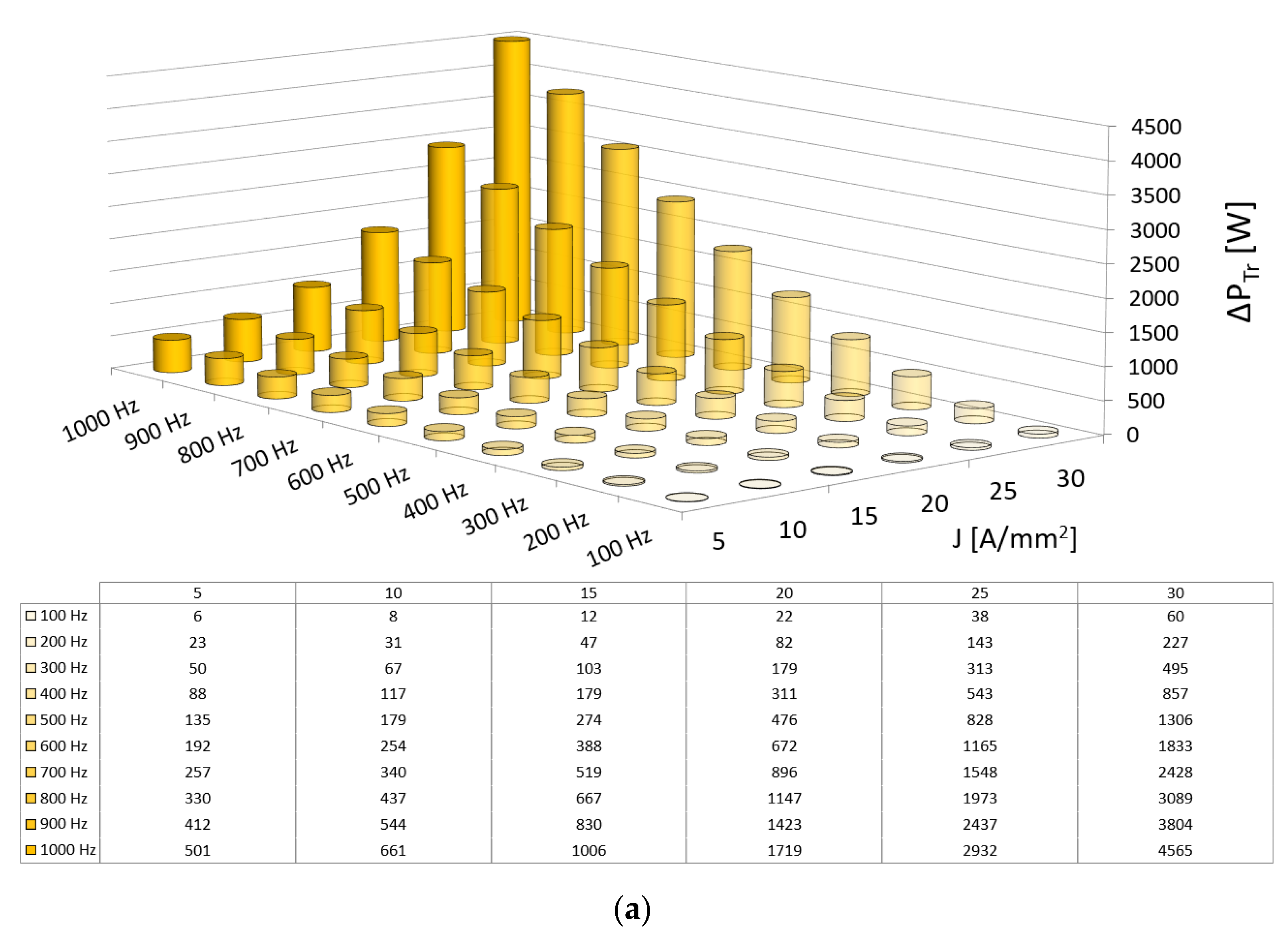
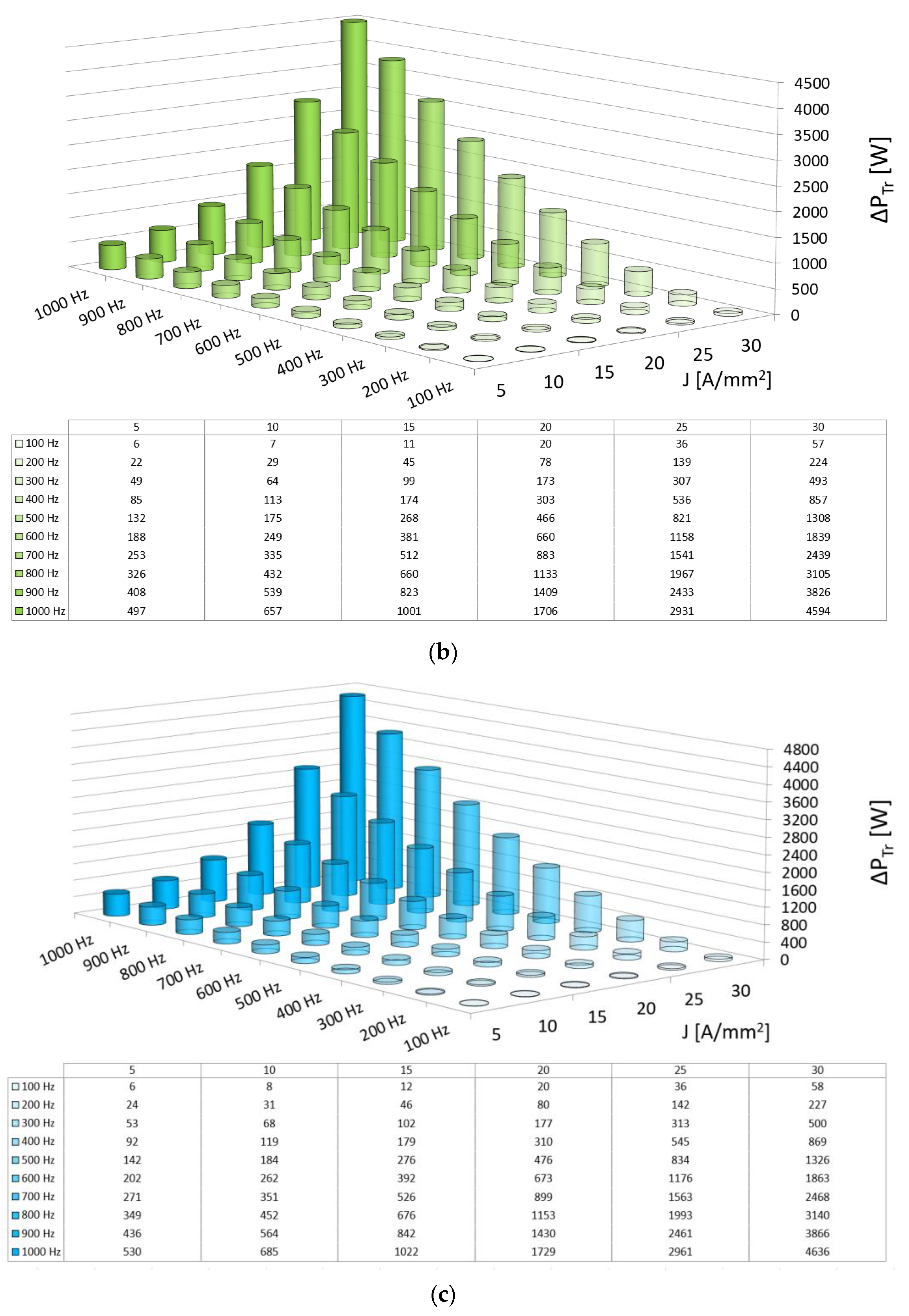
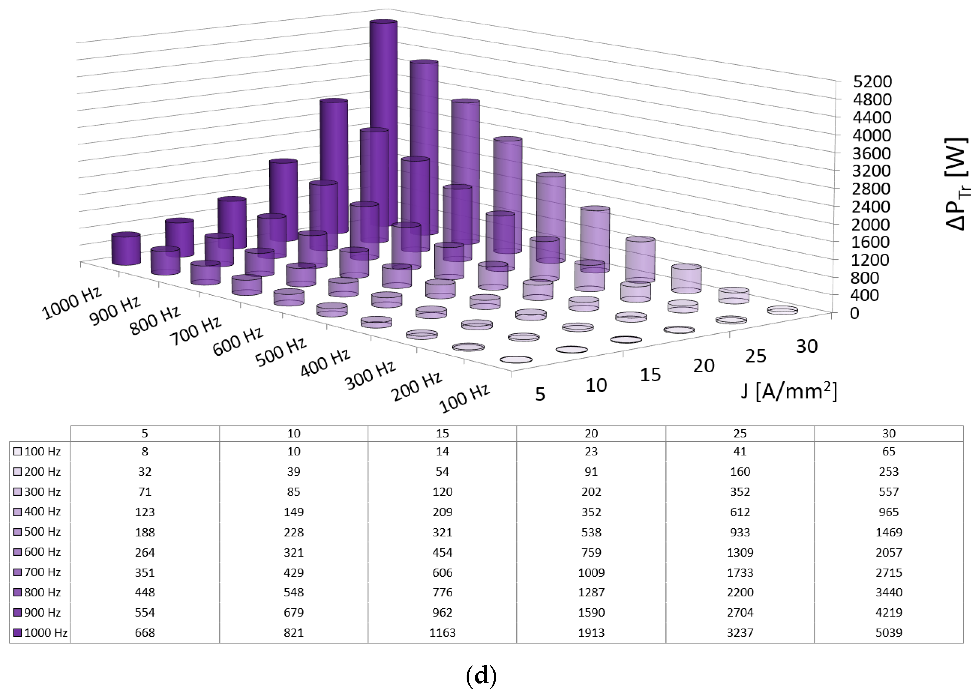
From the results presented in Table 3 and Table 4, significant differences in the rotor core losses between the solid rotor core S355j2 steel and other solutions should be noticed. Both the use of the SMC core and the laminated cores allow for a drastic reduction of losses in the rotor yoke. Figure 4 shows a comparison of losses in the rotor yoke for the analyzed variants as a function of the frequency of the supply voltage for the rated current density in the winding J = 15 A/mm2. In analyzing the results from Figure 4, it should be emphasized that the increased losses in the rotor yoke in the solid rotor core S355j2 do not disqualify this solution in the application in a high power density motor. The main decisive factor is the possibility and efficiency of discharging such a losses value, and thus the question of an efficient cooling system.
Another important issue that should be noticed when analyzing the results from Figure 4 is that for all other analyzed materials, except S355j2, the level of reduction of rotor losses in the whole range of supply frequencies is very similar. Therefore, the final selection should mainly take into account material costs and the necessary technological expenditure for the application of individual variants. It seems that among the analyzed solutions, the most advantageous in this respect is the use of classic M400-50A sheets.
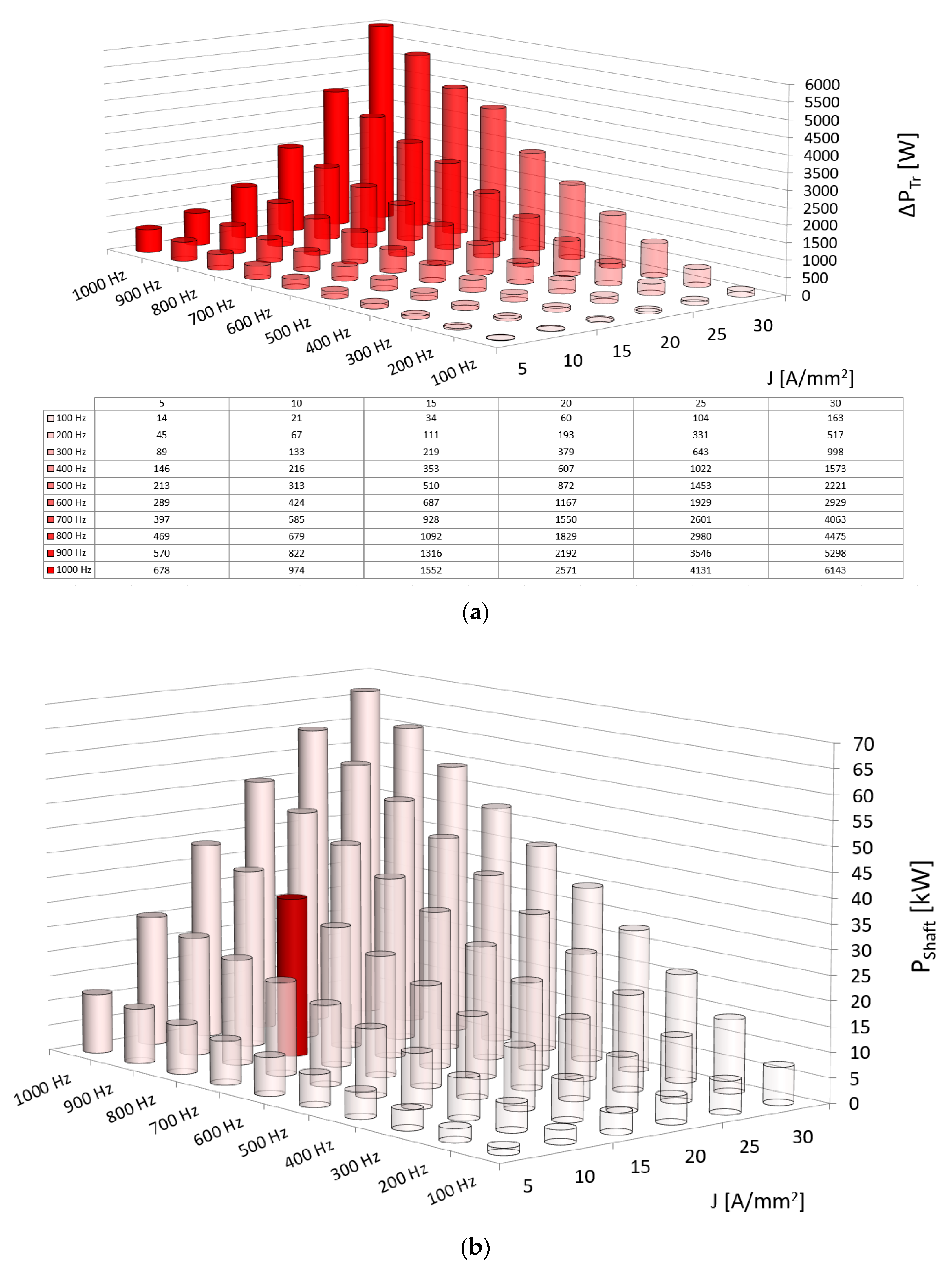
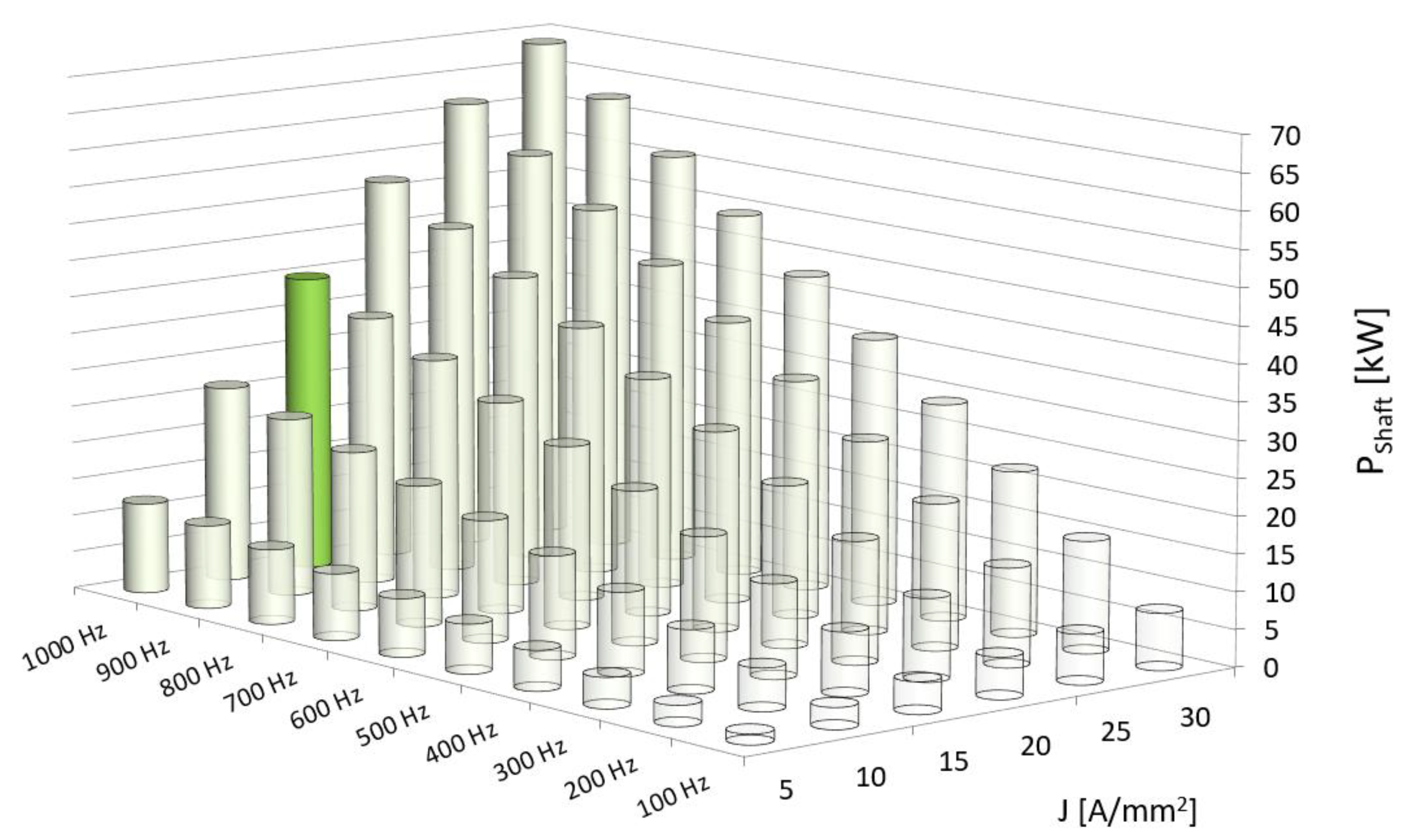
Figure 5a shows the dependence of the total rotor losses ΔPTr as a function of the supply voltage frequency and the load current density for the solid rotor S355j2 solution. The calculated loss values do not consider the segmentation of the permanent magnets. Figure 5b shows the shaft power of the motor with a solid rotor core as a function of the supply frequency and the load current density in the stator winding. The rated operating point is marked with an opaque red color.
When analyzing the results from Figure 5b, it can be seen that the maximum shaft power of the motor, assuming a maximum power frequency of 1000 Hz and a maximum current density in the winding of 30 A/mm2, is approximately 67 kW. For rated current density J = 15 A/mm2, the maximum possible motor shaft power is 39 kW.
For all analyzed variants, the value of the shaft power Pshaft is very similar in the entire range of the supply frequency and the entire range of current loads (Table 3 and Table 4). From the point of view of a high power density motor, the basic question concerns the possible range of operation with continuous (long-term) power. From the conducted thermal simulations, the nominal current density was determined as J = 15 A/mm2. For higher load values, the permissible temperatures in the stator winding were exceeded. Another factor that may limit the range of long-term operation is losses generated in the rotor. These losses cause deterioration of the operating parameters of the motor due to the increase in temperature of permanent magnets and thus their worse magnetic properties. Moreover, these losses may lead to demagnetization of the magnets in the event of exceeding the allowable temperatures.
Figure 6 shows a comparison of the total rotor losses ΔPTr as a function of the supply frequency and the current load for all analyzed variants that are an alternative to the solid rotor core S355j2, for which the total rotor losses are presented in Figure 5a. At the rated operating point, the value of the total rotor losses for the motor with a solid stator core is 1092 W. It can be seen that for the remaining solutions such value level of the total rotor losses ΔPTr for the rated current load is obtained at a supply frequency of 1000 Hz. In taking the above into account, it can be assumed that changing the solid rotor S355j2, e.g., to a laminated rotor M400 (due to the lowest material cost), will allow to increase the range of long-term operation to 1000 Hz, and thus increase the continuous power from 31.8 kW to 40 kW. Then the motor power density factor will increase from ξ = 3.06 kW/kg to ξ = 3.57 kW/kg. Figure 7 shows the shaft power of the motor with the M400 rotor core as a function of the supply frequency and the load current density in the stator winding. The rated operating point is marked with an opaque green color.
5. Experimental Verification
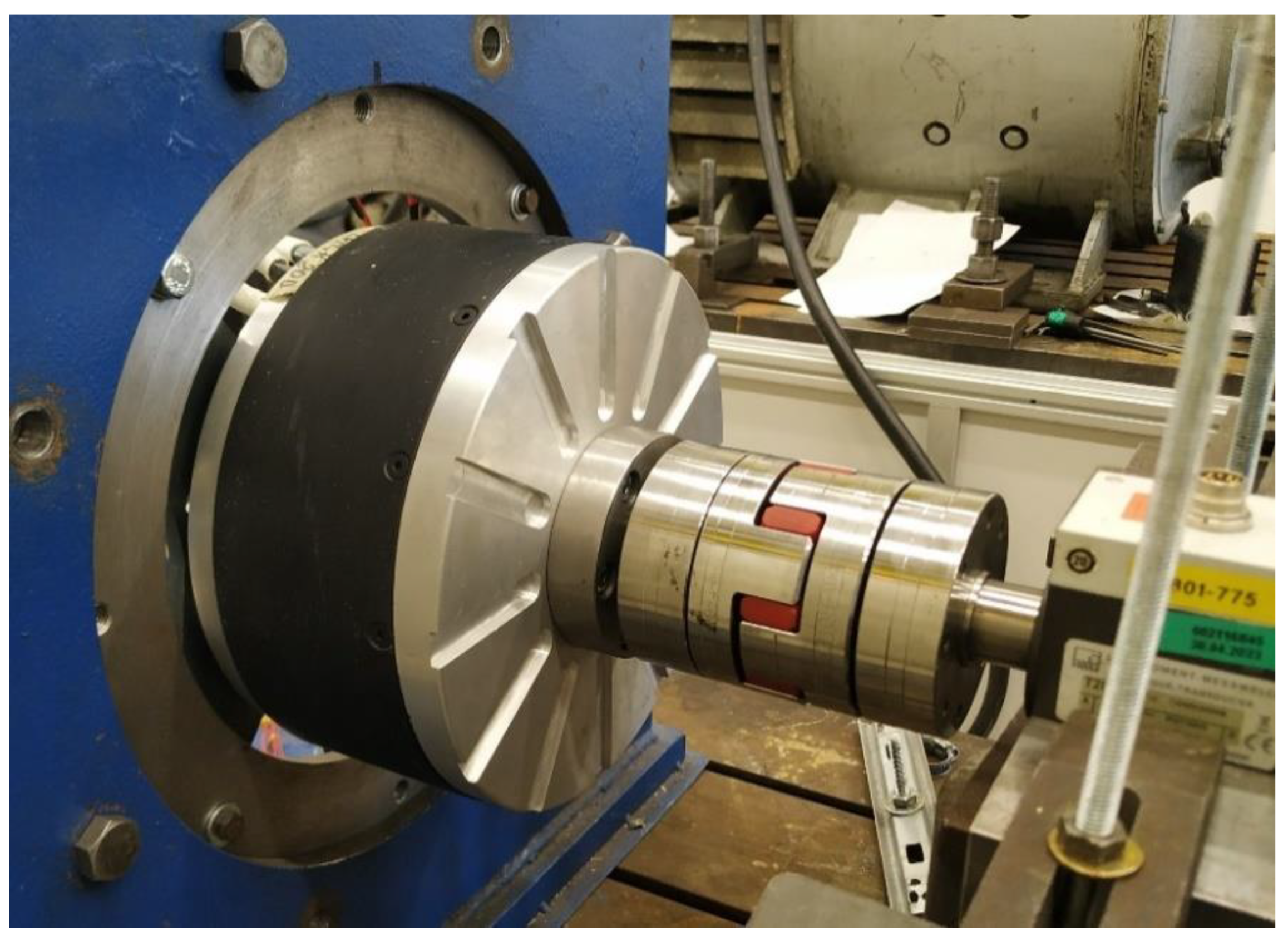
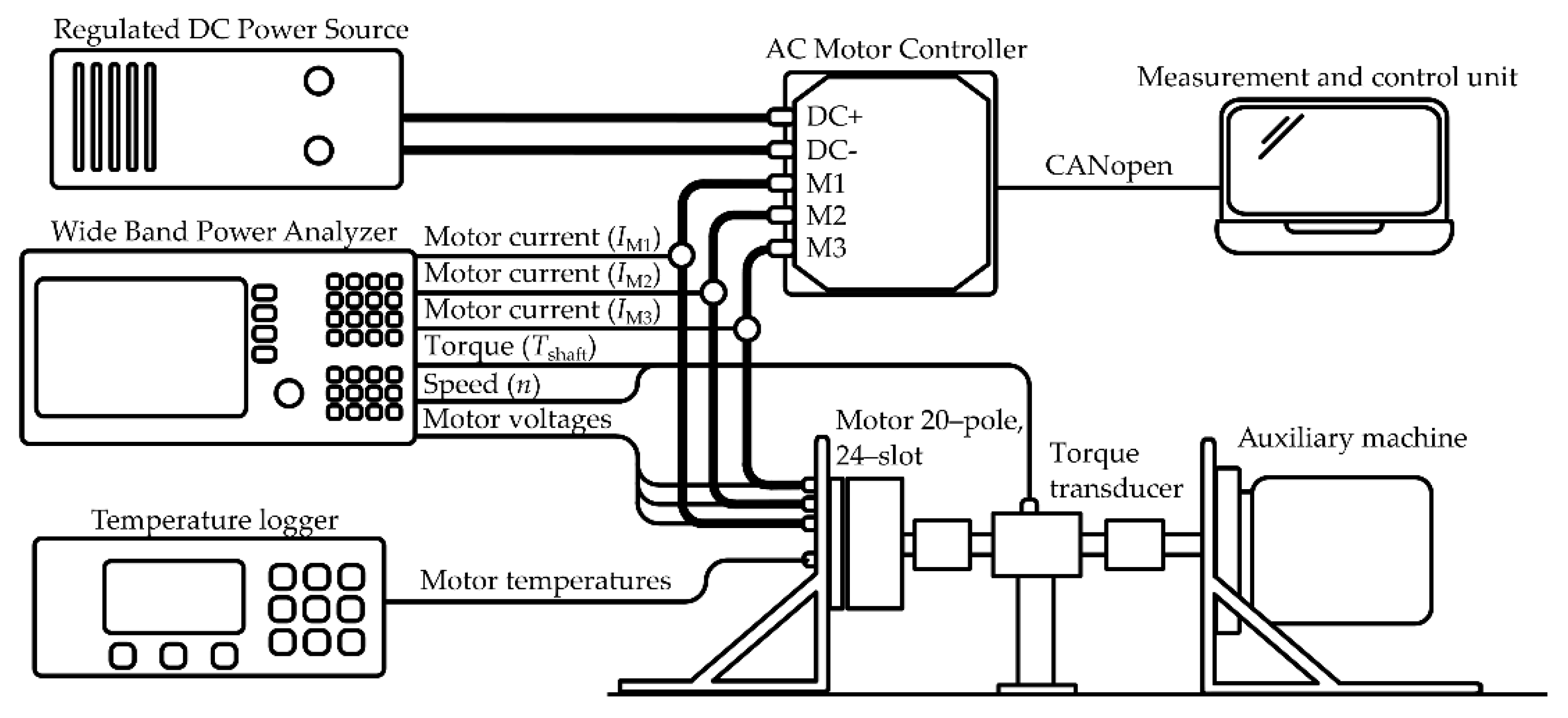
The validation was carried out on a model motor with two rotors made—a solid rotor S355j2 and a laminated rotor M400. Therefore, the models differ only in the rotor yoke, and the other components are identical. In contrast to the FEM models, the model motor uses axial segmentation of magnets (4 segments). Figure 8 shows the model motor installed on the test stand. The tests were carried out with the use of the measuring system shown in Figure 9. The model motor was powered by a Sevcon Gen4 Size8 AC motor controller. Measurements of electrical quantities were made with the use of the ZES Zimmer LMG671 Power analyzer. The measurement of the torque and rotational speed on the shaft was made with the HBM T20WN 200 Nm torque meter. The rotor temperature was measured with the Flir E300 thermal imaging camera, while the winding temperature was recorded from the installed Pt100 sensors. The ambient temperature during the tests was ϑamb = 21 °C.
The results of the laboratory tests are presented in Table 5 (solid rotor S355j2) and Table 6 (laminated M400 rotor). One of the basic objectives of the laboratory tests was to determine the continuous power of the motor and the possible operating area in terms of load current and supply frequency for both solutions. It was assumed that the maximum allowable temperature of the winding was ϑstator = 130 °C. During the tests, the rated current IN was determined for which the current density was J = 13.8 A/mm2; therefore, it was slightly lower than the rated current density of J = 15 A/mm2 assumed during the FEM analysis. In order not to damage the permanent magnets, it was assumed that the maximum permissible rotor temperature was also ϑrot = 130 °C.
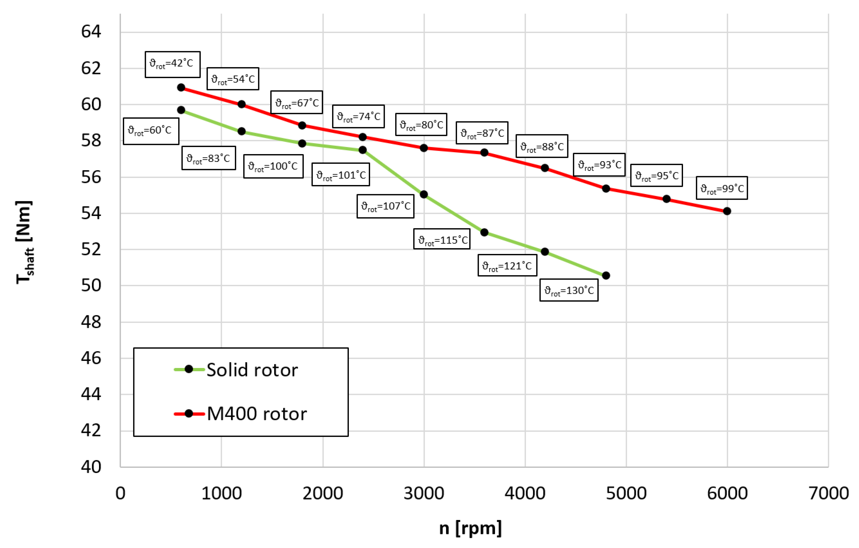
Figure 10 shows a comparison of the shaft torque for solid rotor and laminated M400 rotor as a function of rotational speed for rated current load In. An important issue is the rotor temperatures marked for each operating point. We can see that above the rotational speed of n = 2400 rpm, there is an increase in the difference in the received shaft torque. The main reason is the difference between the rotor temperature of the motor with the solid rotor S355j2 and the laminated M400 rotor. As the temperature increases, the parameters of permanent magnets deteriorate, which in turn translates into the shaft torque obtained. For the motor with a solid rotor above the rotational speed n = 4800 rpm, the operation was not possible due to the exceeded permissible operating temperatures of the rotor. For a motor with a laminated rotor, the range of permissible operation was possible up to a speed n = 6000 rpm and further limited by the possibility of the inverter working. The rotor temperature at this operating point was 99 °C.
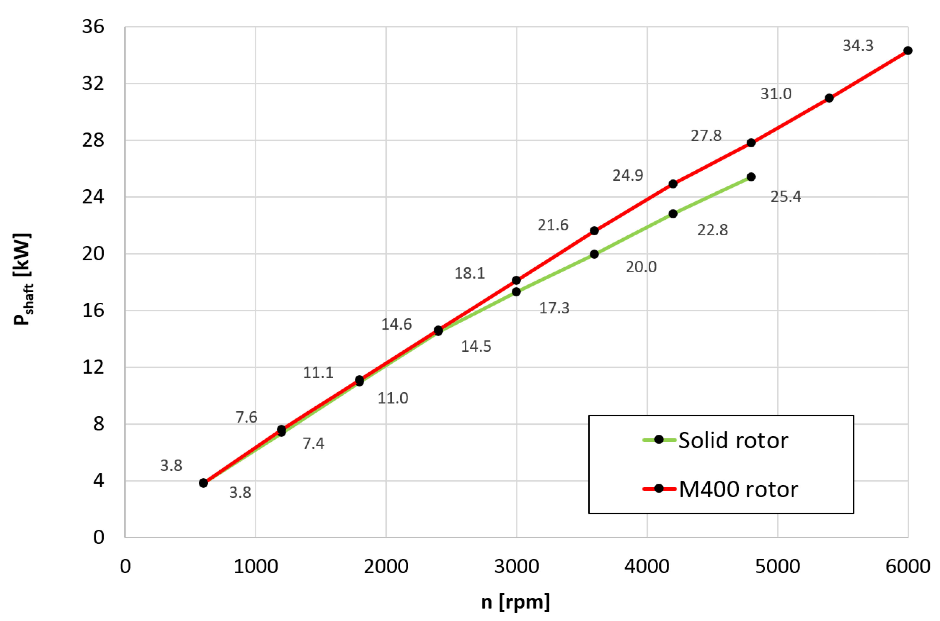
Obviously, the differences in the shaft torque values have a direct impact on the power obtained from the motor. Figure 11 shows the dependence of the shaft power as a function of changes in rotational speed for the rated load current. The difference between the compared solutions due to the higher value of the torque obtained for the rotational speed n = 4800 rpm is as much as 2.4 kW, i.e., approximately 10% of the shaft power. Moreover, it should be noted that due to the extended operating range of the motor (due to the reduction of the rotor temperature), the motor can run at a continuous power of 34.4 kW instead of 25.4 kW, thus an increase of 35%.
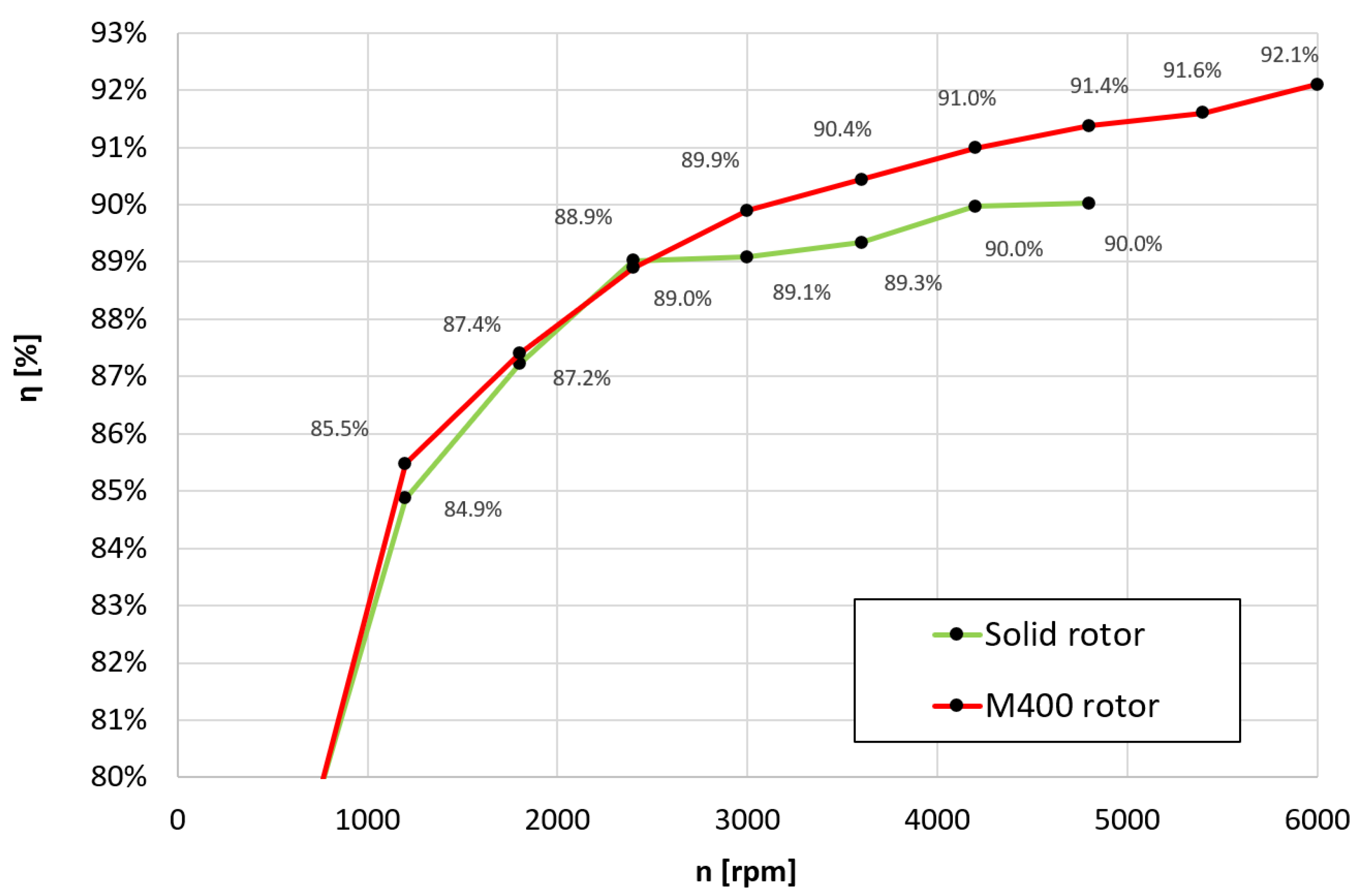
Figure 12 shows a comparison of the efficiency for a motor with a solid core and a motor with a laminated M400 core. The efficiency of the laminated core motor is 0.7–1.4% higher above the speed n = 2400 rpm.
6. Conclusions
The aim of this study was to compare a high power density motor with a solid rotor core and a laminated rotor core. The FEM analysis was carried out, taking into account the possibility of using various materials in the rotor yoke, and then the results were validated for two physical models. The main attention was focused on comparing the values of rotor losses, shaft power and shaft torque, efficiency and the power density factor. The differences in the values of shaft torque and shaft power obtained in FEM simulations and lab tests are the result of a difference in the nominal current densities (15 A/mm2—calculations, 13.7 A/mm2—lab tests) and the adopted temperature values of permanent magnets (80 °C—calculations, 130 °C—lab tests).
When analyzing the results of the work, it can be concluded that the use of a solid rotor core simplifies the design and technology of the rotor and has a lighter motor weight, but the rotor losses are much greater than a motor with laminated rotor cores. However, the analysis does not show that the use of a solid rotor core in a high power density motor is not possible. The motor with the solid rotor core was operated up to a maximum speed of 4800 rpm (800 Hz supply frequency), achieving a continuous power of 25.4 kW. However, the change of the core to a laminated core allowed, firstly, to increase the continuous power at the speed of 4800 rpm to the value of 27.8 kW due to the reduction of the rotor temperature; secondly, it allowed to increase the operating range to the rotational speed of 6000 rpm and obtain a continuous power of 34.3 kW. Therefore, it can be concluded that the predictions after the FEM analysis were confirmed. As a result, the motor’s power density factor increased from 2.49 kW/kg to 3.0 kW/kg (20.5%). On the other hand, the comparison of the power density factors for the speed of 4800 rpm is very similar for both solutions; nevertheless, the laminated rotor core allows 35% more shaft power and 20.5% more power density. The motor with a laminated core gets more power (27.4 kW), but is also heavier. Ultimately, this results in a comparable power density factor for the same rotational speed of 4800 rpm.
Author Contributions
T.W.—development of computational models, simulation, designing of electromagnetic circuits, analysis of simulation results, preparation of the article. T.J.— participation in the creation of proposals, conducting laboratory tests, analysis of test results, editorial article. All authors have read and agreed to the published version of the manuscript.
Funding
The National Center for Research and Development (NCBR), project LIDER/31/0169/L-12/20/NCBR/2021 (POLAND).
Institutional Review Board Statement
Not applicable.
Informed Consent Statement
Not applicable.
Data Availability Statement
Not applicable.
Conflicts of Interest
The authors declare no conflict of interest.
References
- Ramesh, P.; Lenin, C.N. High Power Density Electrical Machines for Electric Vehicles—Comprehensive Review Based on Material Technology. IEEE Trans. Magn. 2019, 55, 0900121. [Google Scholar] [CrossRef]
- Fulai, G.; Chengning, Z. Oil-cooling method of the permanent magnet synchronous motor for electric vehicle. Energies 2019, 12, 2984. [Google Scholar]
- Nimmana, R.L.S.; Chiba, A. Design of High Power Density Motor for EV Applications. In Proceedings of the 2018 21st International Conference on Electrical Machines and Systems (ICEMS), Jeju, Korea, 7–10 October 2018; pp. 104–108. [Google Scholar]
- El-Refaie, A.M.; Alexander, J.P.; Galioto, S.; Reddy, P.B.; Huh, K.-K.; de Bock, P.; Shen, X. Advanced High-Power-Density Interior Permanent Magnet Motor for Traction Applications. IEEE Trans. Ind. Appl. 2014, 50, 3235–3248. [Google Scholar] [CrossRef]
- Park, H.-J.; Lim, M.-S. Design of High Power Density and High Efficiency Wound-Field Synchronous Motor for Electric Vehicle Traction. IEEE Access 2019, 7, 46677–46685. [Google Scholar] [CrossRef]
- Yang, Z.; Shang, F.; Brown, I.P.; Krishnamurthy, M. Comparative Study of Interior Permanent Magnet, Induction, and Switched Reluctance Motor Drives for EV and HEV Applications. IEEE Trans. Transp. Electrif. 2015, 1, 245–254. [Google Scholar] [CrossRef]
- Sudha, B.; Anusha, V.; Sachin, S. A review: High power density motors for electric vehicles. Proceedings of First International Conference on Advances in Physical Sciences and Materials. IOP Publ. J. Phys. 2020, 1706, 012057. [Google Scholar]
- Wolnik, T.; Dukalski, P.; Będkowski, B.; Jarek, T. Selected aspects of designing motor for direct vehicle wheel drive. Prz. Elektrotechniczny (Electr. Rev.) 2020, 96, 150–153. [Google Scholar] [CrossRef]
- Dukalski, P.; Będkowski, B.; Parczewski, K.; Wnęk, H.; Urbaś, A.; Augustynek, K. Dynamics of the vehicle rear suspension system with electric motor mounted in wheels. Eksploat. Niezawodn. 2019, 21, 125–136. [Google Scholar] [CrossRef]
- Wolnik, T. Investigation of properties of disk-type motor electromagnetic circuit using alternative materials in stator/rotor core. Prz. Elektrotechniczny (Electr. Rev.) 2019, 95, 59–63. [Google Scholar] [CrossRef]
- Wolnik, T.; Styskala, V.; Mlcak, T. Study on the Selection of the Number of Magnetic Poles and the Slot-Pole Combinations in Fractional Slot PMSM Motor with a High Power Density. Energies 2021, 15, 215. [Google Scholar] [CrossRef]
- Bianchi, N.; Bolognani, S.; Fomasiero, E. A General Approach to Determine the Rotor Losses in Three-Phase Fractional-Slot PM Machines. In Proceedings of the IEEE International Electric Machines & Drives Conference, Antalya, Turkey, 3–5 May 2007; pp. 634–641. [Google Scholar]
- Ishak, D.; Zhu, Z.Q.; Howe, D. Eddy-current loss in the rotor magnets of permanent-magnet brushless machines having a fractional number of slots per pole. IEEE Trans. Magn. 2005, 41, 2462–2469. [Google Scholar] [CrossRef] [Green Version]
- Yu, X.; Guoli, L.; Zhe, Q.; Qiubo, Y.; Zhenggen, Z. Research on rotor magnet loss in fractional-slot concentrated-windings permanent magnet motor. In Proceedings of the 2016 IEEE 11th Conference on Industrial Electronics and Applications (ICIEA), Hefei, China, 5–7 June 2016; pp. 1616–1620. [Google Scholar]
- Atallah, K.; Howe, D.; Mellor, P.H.; Stone, D.A. Rotor loss in permanent-magnet brushless AC machines. IEEE Trans. Ind. Appl. 2000, 36, 1612–1618. [Google Scholar]
- Sang-Yub, L.; Hyun-Kyo, J. Eddy current loss analysis in the rotor of permanent magnet traction motor with high power density. In Proceedings of the 2012 IEEE Vehicle Power and Propulsion Conference (VPPC), Seoul, Korea, 9–12 October 2012; pp. 210–214. [Google Scholar]
- Toda, H.; Xia, Z.; Wang, J.; Atallah, K.; Howe, D. Rotor Eddy-Current Loss in Permanent Magnet Brushless Machines. IEEE Trans. Magn. 2004, 40, 2104–2106. [Google Scholar] [CrossRef] [Green Version]
- Nakano, M.; Kometani, H.; Kawamura, M. A study on eddy-current losses in rotors of surface permanent-magnet synchronous machines. IEEE Trans. Ind. Appl. 2006, 42, 429–435. [Google Scholar] [CrossRef]
- Yamazaki, K.; Fukushima, Y.; Sato, M. Loss Analysis of Permanent-Magnet Motors with Concentrated Windings—Variation of Magnet Eddy-Current Loss Due to Stator and Rotor Shapes. IEEE Trans. Ind. Appl. 2009, 45, 1334–1342. [Google Scholar] [CrossRef]
- Yunkai, H.; Jianning, D.; Long, J.; Jianguo, Z.; Youguang, G. Eddy-Current Loss Prediction in the Rotor Magnets of a Permanent Magnet Synchronous Generator With Modular Winding Feeding a Rectifier Load. IEEE Trans. Magn. 2011, 47, 4203–4206. [Google Scholar]
- Wang, X.; Liu, D.; Lahaye, D.; Polinder, H.; Ferreira, J.A. Finite element analysis and experimental validation of eddy current losses in permanent magnet machines with fractional-slot concentrated windings. In Proceedings of the IEEE 19th International Conference on Electrical Machines and Systems (ICEMS), Chiba, Japan, 13–16 November 2016. [Google Scholar]
- Gengji, W.; Qinglei, Q.; Ping, W.; Xiaoyuan, W. Analysis of the rotor loss in a high speed permanent magnet motor for flywheel energy storage system. In Proceedings of the IEEE 2015 18th International Conference on Electrical Machines and Systems (ICEMS), Thailand, Pattaya, 25–28 October 2015; pp. 2040–2044. [Google Scholar]
- Belli, Z.; Mekideche, M.R. Optimization of Magnets Segmentation for Eddy Current Losses Reduction in Permanent Magnets Electrical Machines. In Proceedings of the 2013 Eighth International Conference and Exhibition on Ecological Vehicles and Renewable Energies (EVER), Monte Carlo, Monaco, 27–30 March 2013. [Google Scholar] [CrossRef]
- Yamazaki, K.; Shina, M.; Kanou, Y.; Miwa, M.; Hagiwara, J. Effect of Eddy Current Loss Reduction by Segmentation of Magnets in Synchronous Motors: Difference Between Interior and Surface Types. IEEE Trans. Magn. 2009, 45, 4756–4759. [Google Scholar] [CrossRef]
- Ede, J.D.; Atallah, K.; Jewell, G.W.; Wang, J.B.; Howe, D. Effect of Axial Segmentation of Permanent Magnets on Rotor Loss in Modular Permanent-Magnet Brushless Machines. IEEE Trans. Ind. Appl. 2007, 43, 1207–1213. [Google Scholar] [CrossRef]
- Huang, W.-Y.; Bettayeb, A.; Kaczmarek, R.; Vannier, J.-C. Optimization of Magnet Segmentation for Reduction of Eddy-Current Losses in Permanent Magnet Synchronous Machine. IEEE Trans. Energy Convers. 2010, 25, 381–387. [Google Scholar] [CrossRef] [Green Version]
- Yu, Y.; Liang, D.; Liu, X. Optimal Design of the Rotor Structure of a HSPMSM Based on Analytic Calculation of Eddy Current Losses. Energies 2017, 10, 551. [Google Scholar] [CrossRef] [Green Version]
- Berhausen, S.; Jarek, T. Analysis of Impact of Design Solutions of an Electric Machine with Permanent Magnets for Bearing Voltages with Inverter Power Supply. Energies 2022, 15, 4475. [Google Scholar] [CrossRef]
- Wang, J.; Patel, V.I.; Wang, W. Fractional-Slot Permanent Magnet Brushless Machines with Low Space Harmonic Contents. IEEE Trans. Magn. 2013, 50, 8200209. [Google Scholar] [CrossRef]
- Bianchi, N.; Pre, M.D. Use of the star of slots in designing fractional-slot single-layer synchronous motors. IEE Proc.-Electr. Power Appl. 2006, 153, 459–466. [Google Scholar] [CrossRef]
- Zhao, N.; Zhu, Z.Q.; Liu, W. Rotor Eddy Current Loss Calculation and Thermal Analysis of Permanent Magnet Motor and Generator. IEEE Trans. Magn. 2011, 47, 4199–4202. [Google Scholar] [CrossRef]
Figure 1.
(a) Cross-section of a fragment of motor with a solid rotor; (b) cross-section of a fragment of motor with a laminated rotor, where 1—stator winding, 2—solid rotor yoke, 3—permanent magnets, 4—laminated rotor yoke.
Figure 1.
(a) Cross-section of a fragment of motor with a solid rotor; (b) cross-section of a fragment of motor with a laminated rotor, where 1—stator winding, 2—solid rotor yoke, 3—permanent magnets, 4—laminated rotor yoke.

Figure 2.
Distribution of the magnetomotive force MMF for a motor with a number of poles 2p = 20 and number of stator slots Qs = 24.
Figure 2.
Distribution of the magnetomotive force MMF for a motor with a number of poles 2p = 20 and number of stator slots Qs = 24.

Figure 3.
Distribution of the flux density from permanent magnets in the elements of the electromagnetic circuit of the motor model.
Figure 3.
Distribution of the flux density from permanent magnets in the elements of the electromagnetic circuit of the motor model.

Figure 4.
The value of the calculated losses in the rotor yoke ΔPYr for individual solutions as a function of the supply frequency for the current density in the winding J = 15 A/mm2.
Figure 4.
The value of the calculated losses in the rotor yoke ΔPYr for individual solutions as a function of the supply frequency for the current density in the winding J = 15 A/mm2.

Figure 5.
The value of (a) total rotor losses ΔPTr; (b) shaft power as a function of the supply frequency and current density in the winding for solid rotor S355j2.
Figure 5.
The value of (a) total rotor losses ΔPTr; (b) shaft power as a function of the supply frequency and current density in the winding for solid rotor S355j2.

Figure 6.
The value of total rotor losses ΔPTr (a) SMC rotor; (b) M400 rotor; (c) NO27 rotor; (d) Vacoflux rotor.
Figure 6.
The value of total rotor losses ΔPTr (a) SMC rotor; (b) M400 rotor; (c) NO27 rotor; (d) Vacoflux rotor.


Figure 7.
The value of shaft power as a function of the supply frequency and current density in the winding for M400 rotor.
Figure 7.
The value of shaft power as a function of the supply frequency and current density in the winding for M400 rotor.

Figure 8.
Model motor on a test stand.

Figure 9.
Scheme of the measurement system for model motor.

Figure 10.
Comparison of the shaft torque as a function of changes in rotational speed for the rated load current IN.
Figure 10.
Comparison of the shaft torque as a function of changes in rotational speed for the rated load current IN.

Figure 11.
Comparison of the shaft power as a function of rotational speed for the rated load current IN.
Figure 11.
Comparison of the shaft power as a function of rotational speed for the rated load current IN.

Figure 12.
Comparison of the efficiency as a function of changes in rotational speed for the rated load current IN.
Figure 12.
Comparison of the efficiency as a function of changes in rotational speed for the rated load current IN.


Table 1.
Basic data for the analyzed motor models.
| Parameter | ||
|---|---|---|
| DC supply voltage | V | 400 |
| Rated rotational speed | Rpm | 4800 |
| Rated current density | A/mm2 | 15 |
| Phase advance angle | - | 0 |
| Flux weaking | - | none |
| Outer diameter of rotor core | mm | 200 |
| Length of core | mm | 50 |
| Phase number | - | 3 |
| Number of poles | - | 20 |
| Number of stator slots | - | 24 |
| Winding temperature | °C | 120 |
| PM temperature | °C | 80 |
| Stator core material type | - | NO27, 0.27 mm |
| Type of magnets | - | N45SH |
| Solid rotor core motor weight | kg | 10.2 |
| Laminated rotor core motor weight | kg | 11.4 |
Table 2.
Basic properties of the analyzed materials in the rotor yoke.
| Model Name | Type of Material | Cond. | Mass Density | Coefficient | Cost | ||
|---|---|---|---|---|---|---|---|
| Kh | Kc | Ke | |||||
| MS/m | kg/m3 | W/m3 | p.u. | ||||
 Solid rotor Solid rotor | S355j2 | 1.95 | 7700 | - | - | - | 1.0 |
 SMC rotor SMC rotor | Somaloy 700 3p | 0.005 | 7500 | 579.1 | 0 | 14.52 | 2.3 |
 M400 rotor M400 rotor | M400-50A | 1.95 | 7700 | 163.2 | 1.28 | 0 | 1.2 |
 NO27 rotor NO27 rotor | NO27 | 1.7 | 7600 | 115.6 | 0.34 | 0.72 | 1.4 |
 Vacoflux rotor Vacoflux rotor | Vacoflux48 | 2.27 | 8120 | 46.4 | 0.014 | 3.67 | 3.5 |
Table 3.
FEM analysis results for the rated rotational speed n = 4800 rpm (f = 800 Hz) and the current density in the winding J = 15 A/mm2.
Table 3.
FEM analysis results for the rated rotational speed n = 4800 rpm (f = 800 Hz) and the current density in the winding J = 15 A/mm2.
| Model | ΔPCu | ΔPFes | ΔPYr | ΔPPM | ΔPTr | ΔPadd | ΔPmech | Pshaft | Tshaft | η | ξ | ϑPM |
|---|---|---|---|---|---|---|---|---|---|---|---|---|
| W | W | W | W | W | W | W | kW | N·m | % | kW/kg | °C | |
| Solid rotor | 1164 | 690 | 522 | 570 | 1092 | 510 | 350 | 31.8 | 63.3 | 89.3 | 3.06 | 119 |
| SMC rotor | 1164 | 686 | 18 | 648 | 667 | 511 | 350 | 32.5 | 64.6 | 90.6 | 3.13 | 81 |
| M400 rotor | 1164 | 690 | 22 | 638 | 660 | 513 | 350 | 32.5 | 64.6 | 90.6 | 2.90 | 81 |
| NO27 rotor | 1164 | 693 | 8 | 668 | 676 | 514 | 350 | 32.5 | 64.7 | 90.5 | 2.90 | 82 |
| Vacoflux rotor | 1164 | 712 | 7 | 776 | 783 | 518 | 350 | 32.7 | 65.0 | 90.3 | 2.90 | 86 |
Table 4.
FEM analysis results for the rated rotational speed n = 4800 rpm (f = 800 Hz) and the current density in the winding J = 30 A/mm2.
Table 4.
FEM analysis results for the rated rotational speed n = 4800 rpm (f = 800 Hz) and the current density in the winding J = 30 A/mm2.
| Model | ΔPCu | ΔPFes | ΔPYr | ΔPPM | ΔPTr | ΔPadd | ΔPmech | Pshaft | Tshaft | η | ξ |
|---|---|---|---|---|---|---|---|---|---|---|---|
| W | W | W | W | W | W | W | kW | N·m | % | kW/kg | |
| Solid rotor | 4655 | 809 | 2393 | 2082 | 4475 | 900 | 350 | 54.4 | 108.2 | 82.9 | 5.22 |
| SMC rotor | 4655 | 842 | 55 | 3034 | 3089 | 902 | 350 | 55.8 | 111.0 | 85.0 | 5.38 |
| M400 rotor | 4655 | 844 | 91 | 3013 | 3104 | 907 | 350 | 56.1 | 111.7 | 85.0 | 5.00 |
| NO27 rotor | 4655 | 849 | 30 | 3109 | 3139 | 907 | 350 | 56.1 | 111.7 | 85.0 | 5.01 |
| Vacoflux rotor | 4655 | 875 | 16 | 3424 | 3440 | 914 | 350 | 56.3 | 112.0 | 84.6 | 4.99 |
Table 5.
The results of tests bench for a model motor with solid rotor S355j2 for the rated load current IN.
Table 5.
The results of tests bench for a model motor with solid rotor S355j2 for the rated load current IN.
| n | f | Pshaft | Tshaft | η | ϑstator | ϑrot |
|---|---|---|---|---|---|---|
| rpm | Hz | kW | N·m | % | °C | °C |
| 600 | 100 | 3.8 | 59.7 | 78.1% | 95 | 60 |
| 1200 | 200 | 7.4 | 58.5 | 84.9% | 105 | 83 |
| 1800 | 300 | 11.0 | 57.8 | 87.2% | 111 | 100 |
| 2400 | 400 | 14.5 | 57.5 | 89.0% | 119 | 101 |
| 3000 | 500 | 17.3 | 55.0 | 89.1% | 120 | 107 |
| 3600 | 600 | 20.0 | 52.9 | 89.3% | 121 | 115 |
| 4200 | 700 | 22.8 | 51.9 | 90.0% | 122 | 121 |
| 4800 | 800 | 25.4 | 50.6 | 90.0% | 130 | 130 |
| 5400 | 900 | - | - | - | - | - |
| 6000 | 1000 | - | - | - | - | - |
Table 6.
The results of tests bench for a model motor with laminated M400 rotor for the rated load current IN.
Table 6.
The results of tests bench for a model motor with laminated M400 rotor for the rated load current IN.
| n | f | Pshaft | Tshaft | η | ϑstator | ϑrot |
|---|---|---|---|---|---|---|
| rpm | Hz | kW | N·m | % | °C | °C |
| 600 | 100 | 3.8 | 60.9 | 77.9 | 86 | 42 |
| 1200 | 200 | 7.6 | 60.0 | 85.5 | 92 | 54 |
| 1800 | 300 | 11.1 | 58.8 | 87.4 | 99 | 67 |
| 2400 | 400 | 14.6 | 58.2 | 88.9 | 104 | 74 |
| 3000 | 500 | 18.1 | 57.6 | 89.9 | 111 | 80 |
| 3600 | 600 | 21.6 | 57.3 | 90.4 | 118 | 87 |
| 4200 | 700 | 24.9 | 56.5 | 91.0 | 122 | 88 |
| 4800 | 800 | 27.8 | 55.4 | 91.4 | 125 | 93 |
| 5400 | 900 | 31.0 | 54.8 | 91.6 | 126 | 95 |
| 6000 | 1000 | 34.0 | 54.1 | 92.1 | 130 | 99 |
Publisher’s Note: MDPI stays neutral with regard to jurisdictional claims in published maps and institutional affiliations. |
© 2022 by the authors. Licensee MDPI, Basel, Switzerland. This article is an open access article distributed under the terms and conditions of the Creative Commons Attribution (CC BY) license (https://creativecommons.org/licenses/by/4.0/).
Share and Cite
MDPI and ACS Style
Wolnik, T.; Jarek, T. Solid Rotor Core vs. Lamination Rotor Core in Fractional-Slot PMSM Motor with High Power Density. Energies 2022, 15, 5729. https://doi.org/10.3390/en15155729
AMA Style
Wolnik T, Jarek T. Solid Rotor Core vs. Lamination Rotor Core in Fractional-Slot PMSM Motor with High Power Density. Energies. 2022; 15(15):5729. https://doi.org/10.3390/en15155729
Chicago/Turabian StyleWolnik, Tomasz, and Tomasz Jarek. 2022. "Solid Rotor Core vs. Lamination Rotor Core in Fractional-Slot PMSM Motor with High Power Density" Energies 15, no. 15: 5729. https://doi.org/10.3390/en15155729
Note that from the first issue of 2016, this journal uses article numbers instead of page numbers. See further details here.