


Nonlinear Control Strategies for Enhancing the Performance of DFIG-Based WECS under a Real Wind Profile

 ,
,  , ,
, ,
Abstract
:1. Introduction
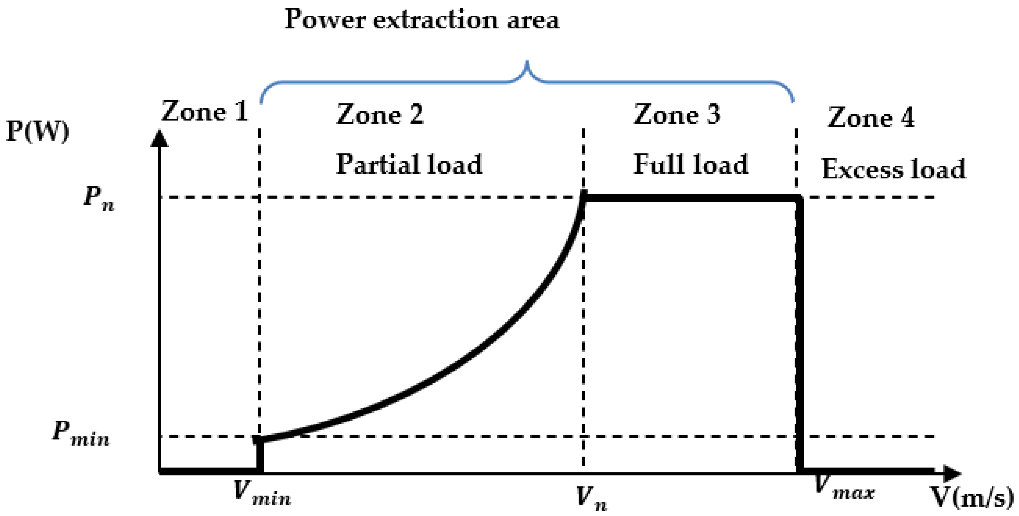
- For the MPPT controller to calculate the optimal generator speed that leads to the maximum power point as the wind speed changes.
- For the pitch angle controller to ensure that the captured mechanical power is below the generator nominal power.
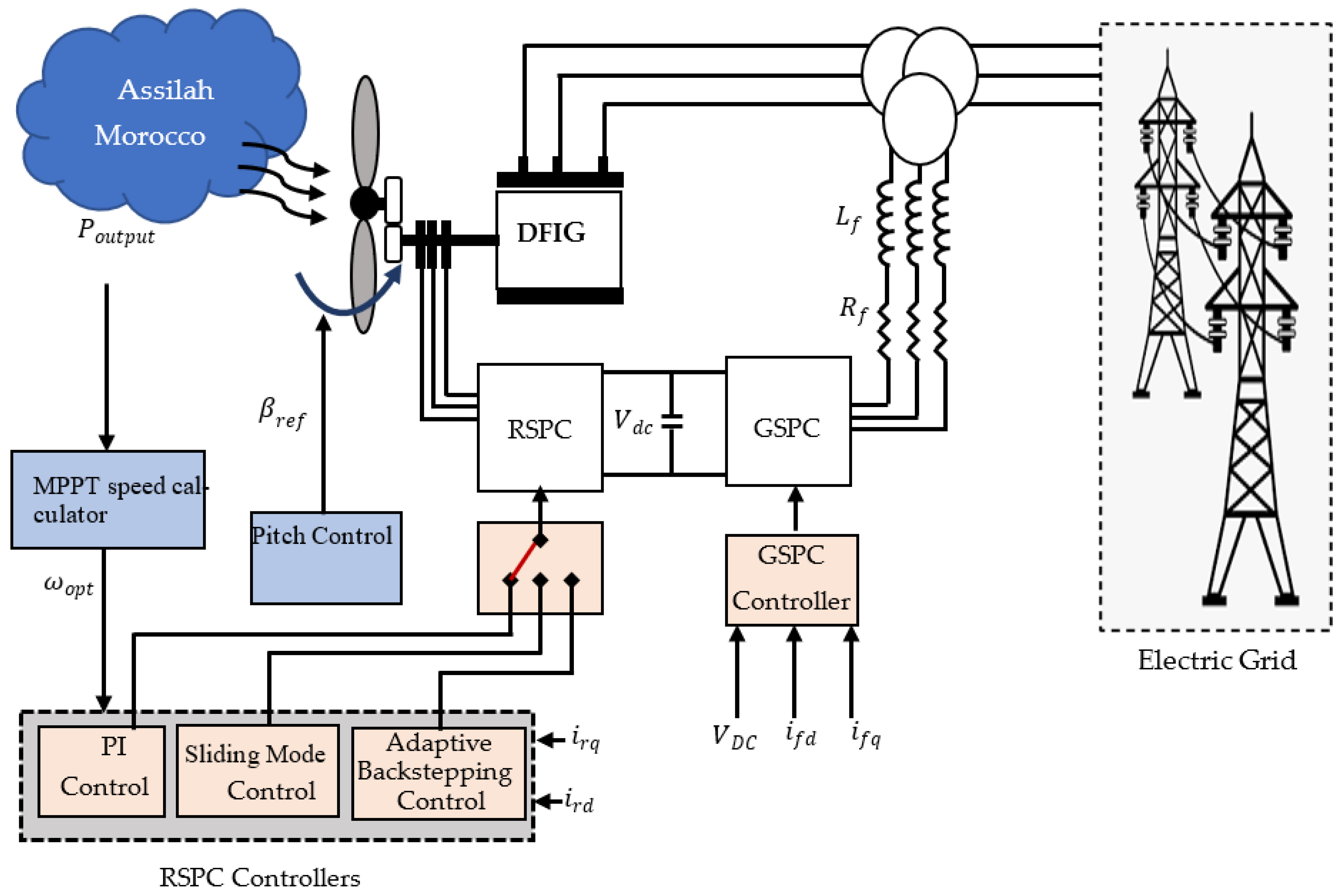
- For the RSPC controller to act on the inverters to track the optimum speed and desired stator reactive power.
- For the GSPC controller, the objectives were to keep the DC-bus voltage constant and annul the reactive power generated by the filter.
- To study the robustness of the proposed controller under parameter uncertainties through some changes in the DFIG parameters.
- To evaluate and compare the ABC designed to control the RSPC to PI and SMC in terms of precision, response time, robustness, and output power quality.
2. System Overview and Modeling
2.1. Turbine Modeling
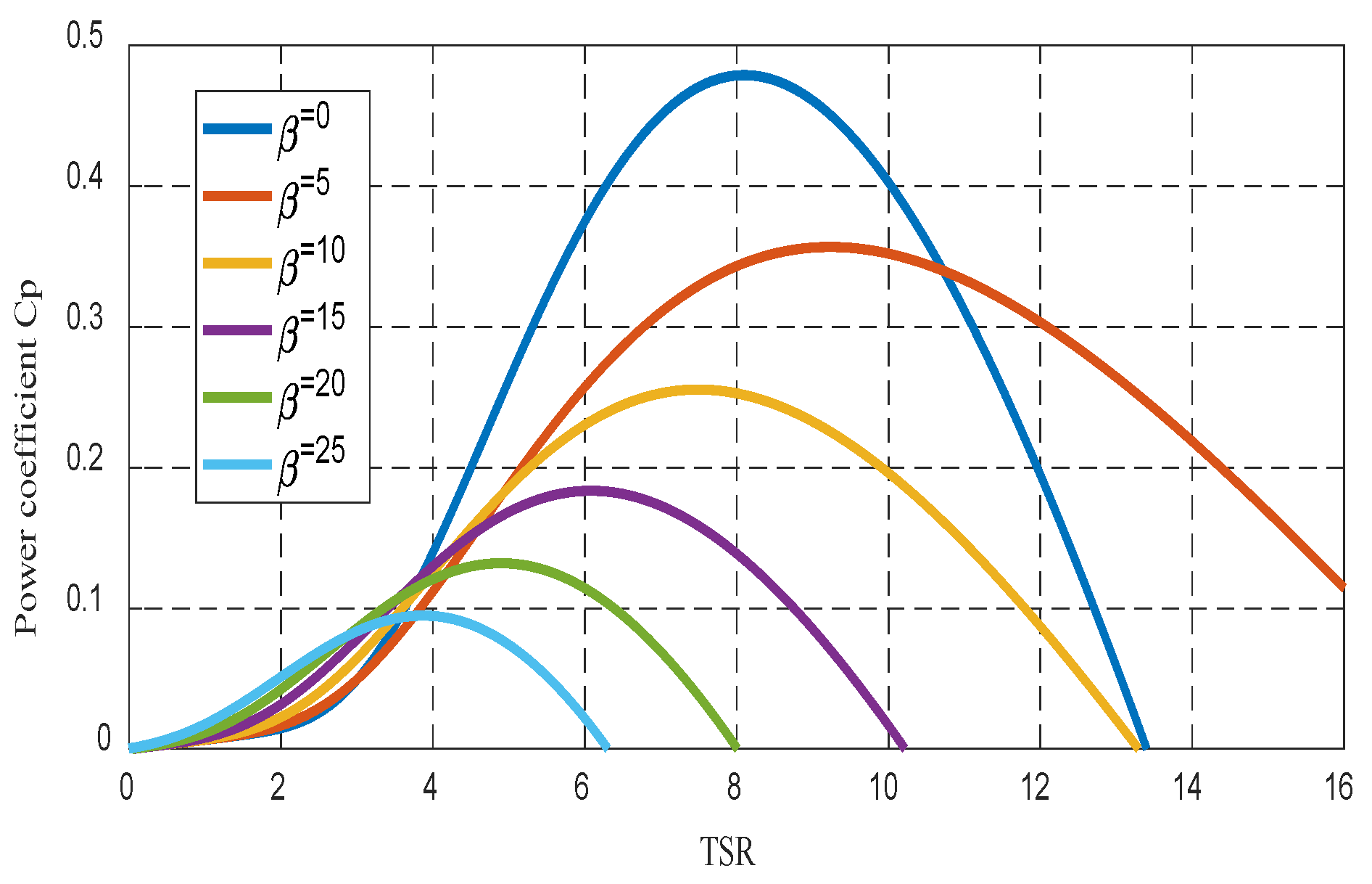
2.1.1. Aerodynamics
2.1.2. Dynamics
2.2. Model of the Rotor-Side Power Converter
2.3. Model of the Grid-Side Power Converter
3. Control Strategy
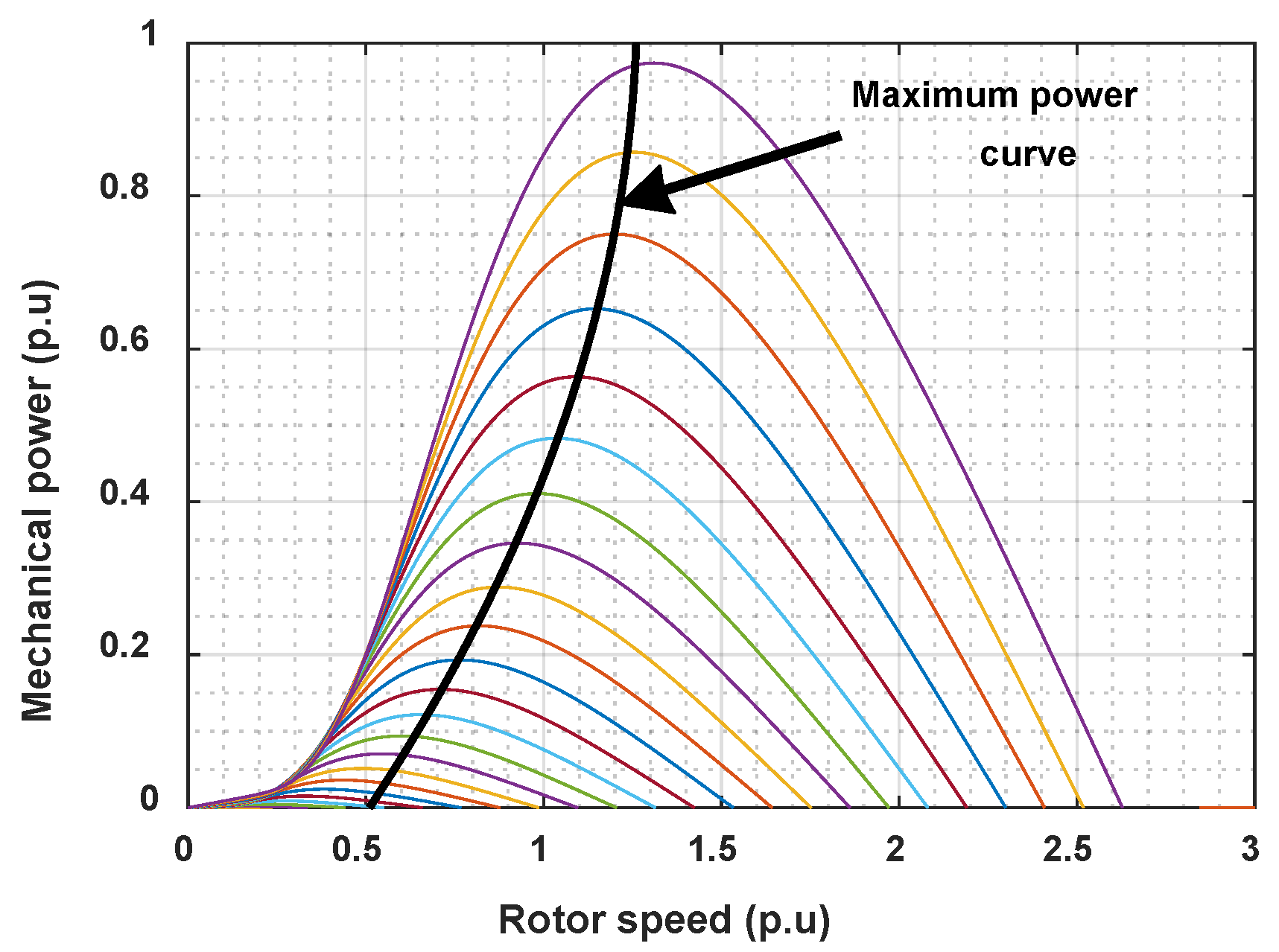
3.1. Curve Fitting MPPT Control (Optimum Speed Calculation)
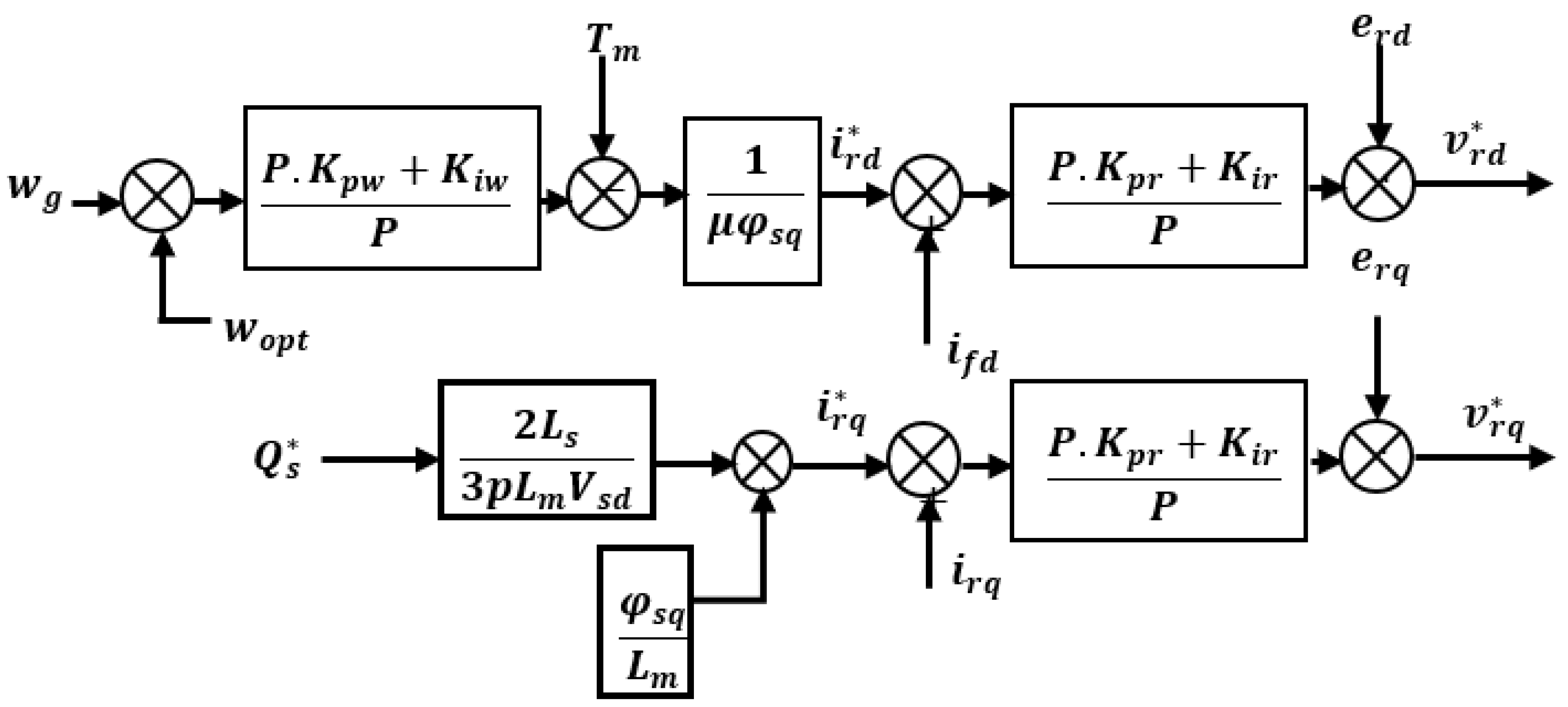
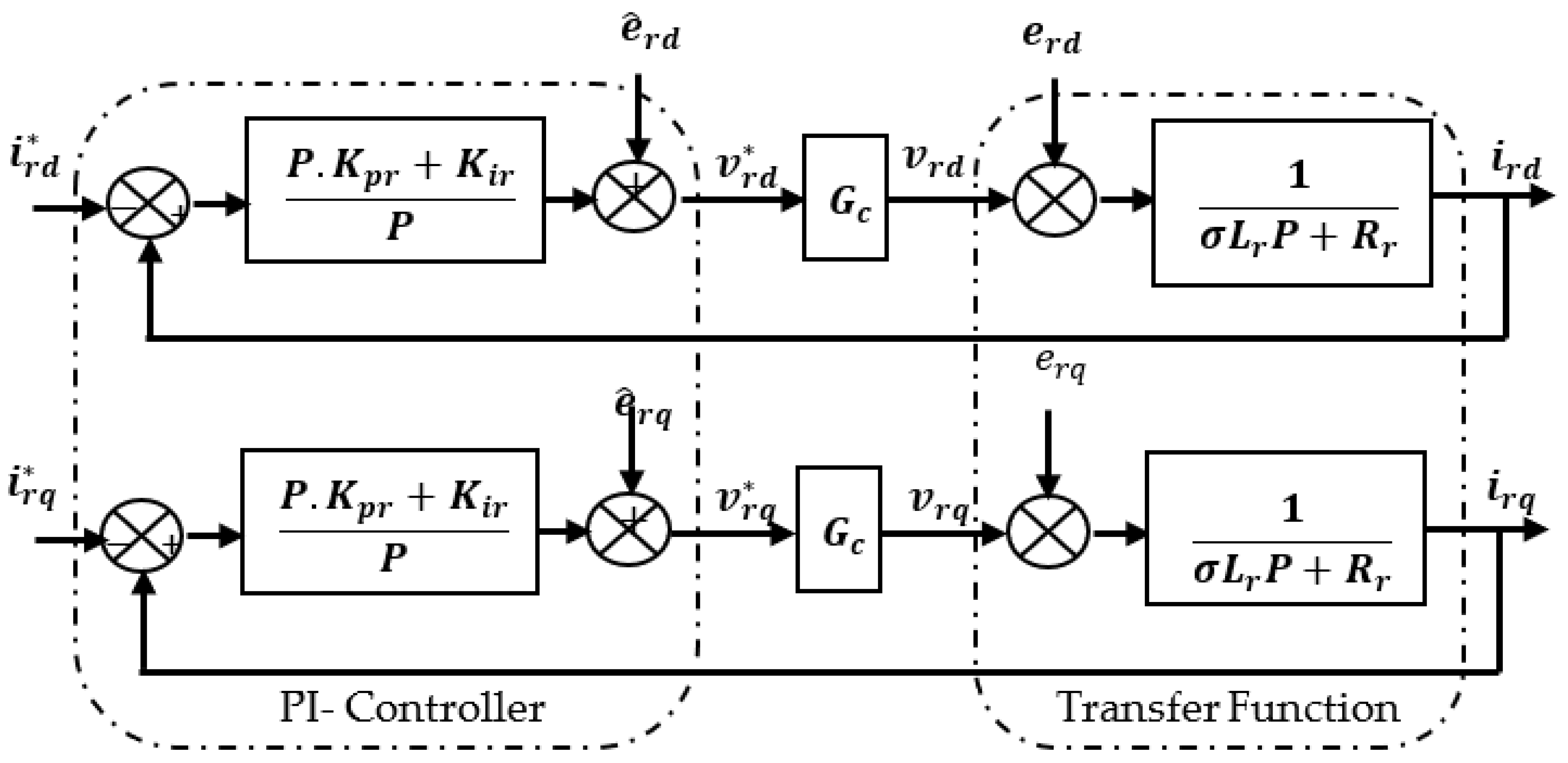
3.2. Rotor-Side Power Converter Control
3.2.1. PI Controller (PIC)
3.2.2. Design of Sliding-Mode Control (SMC)
3.2.3. Adaptive Backstepping Control (ABC)
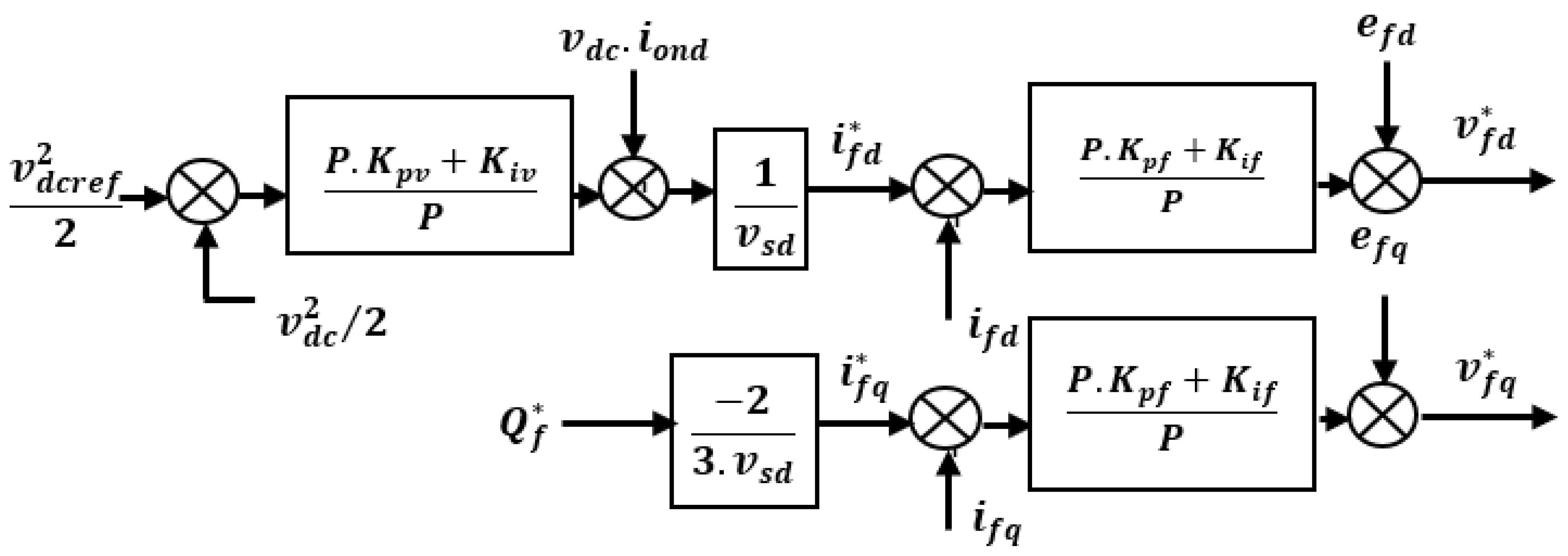
3.3. Filter Reactive Power and DC-Link Voltage Control
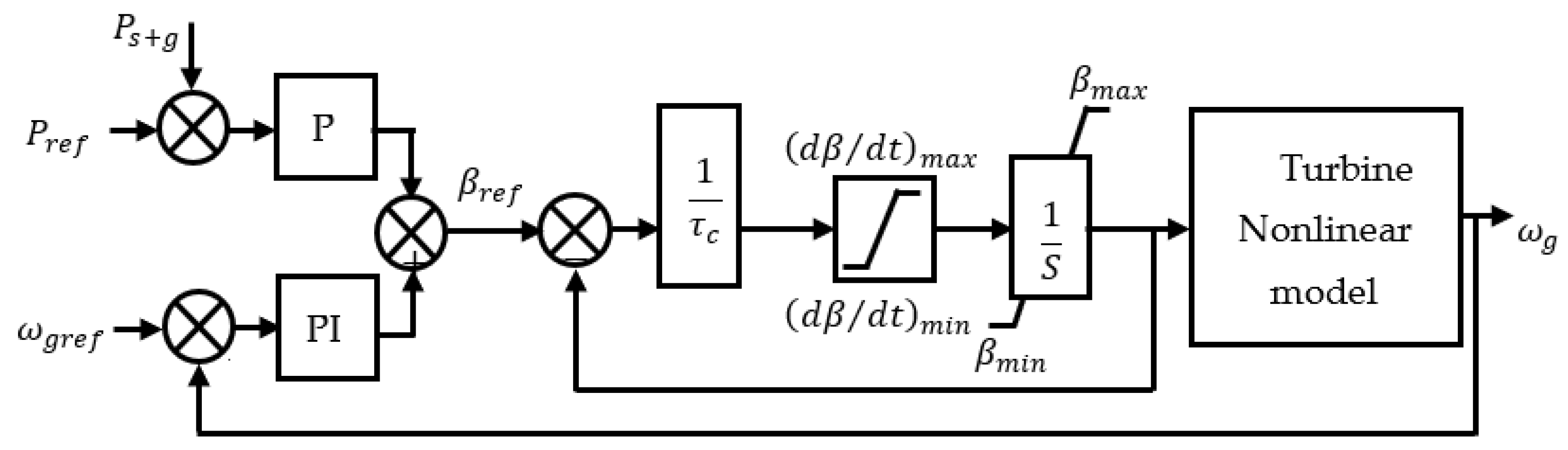
3.4. Pitch Angle Control
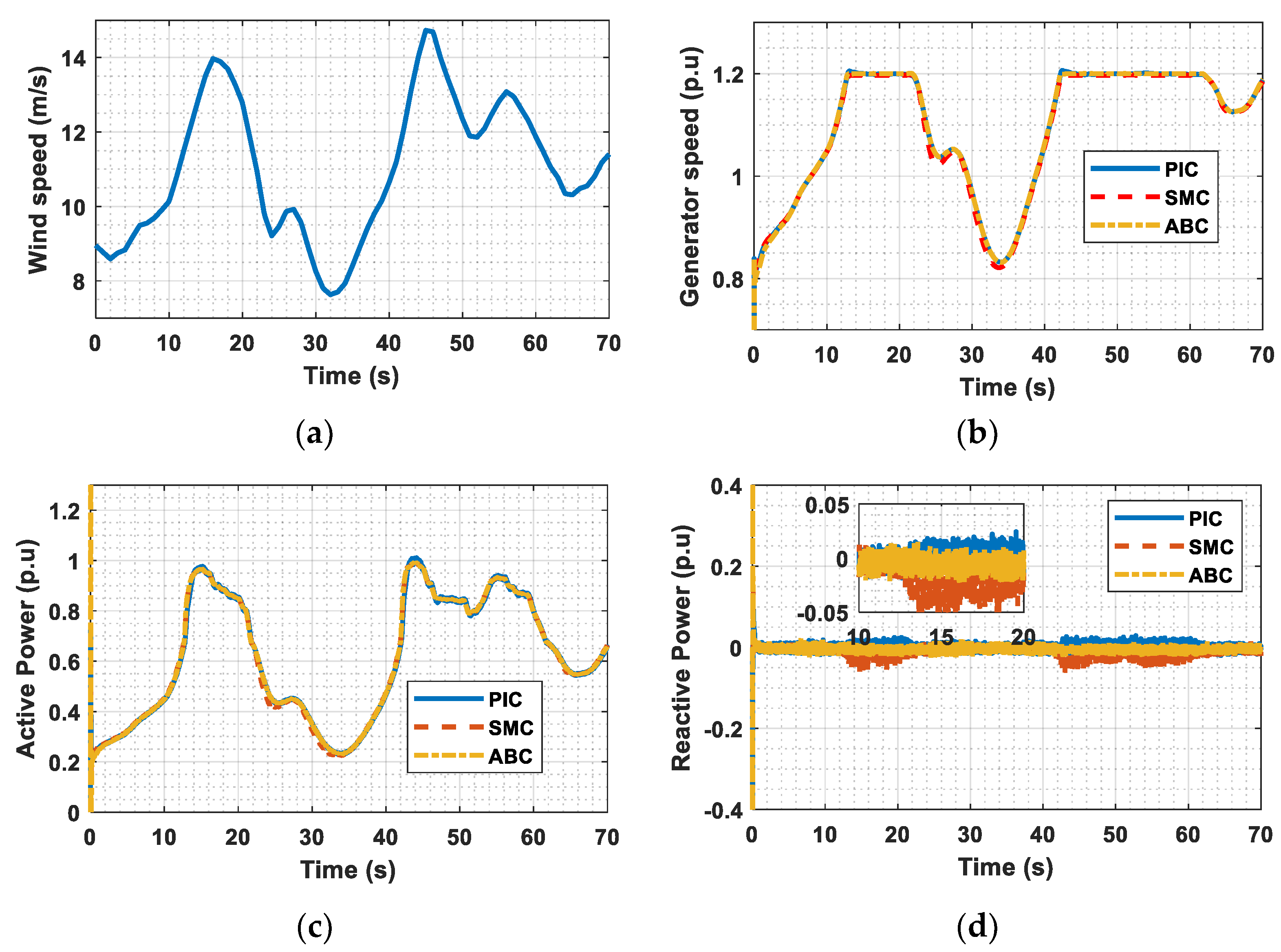
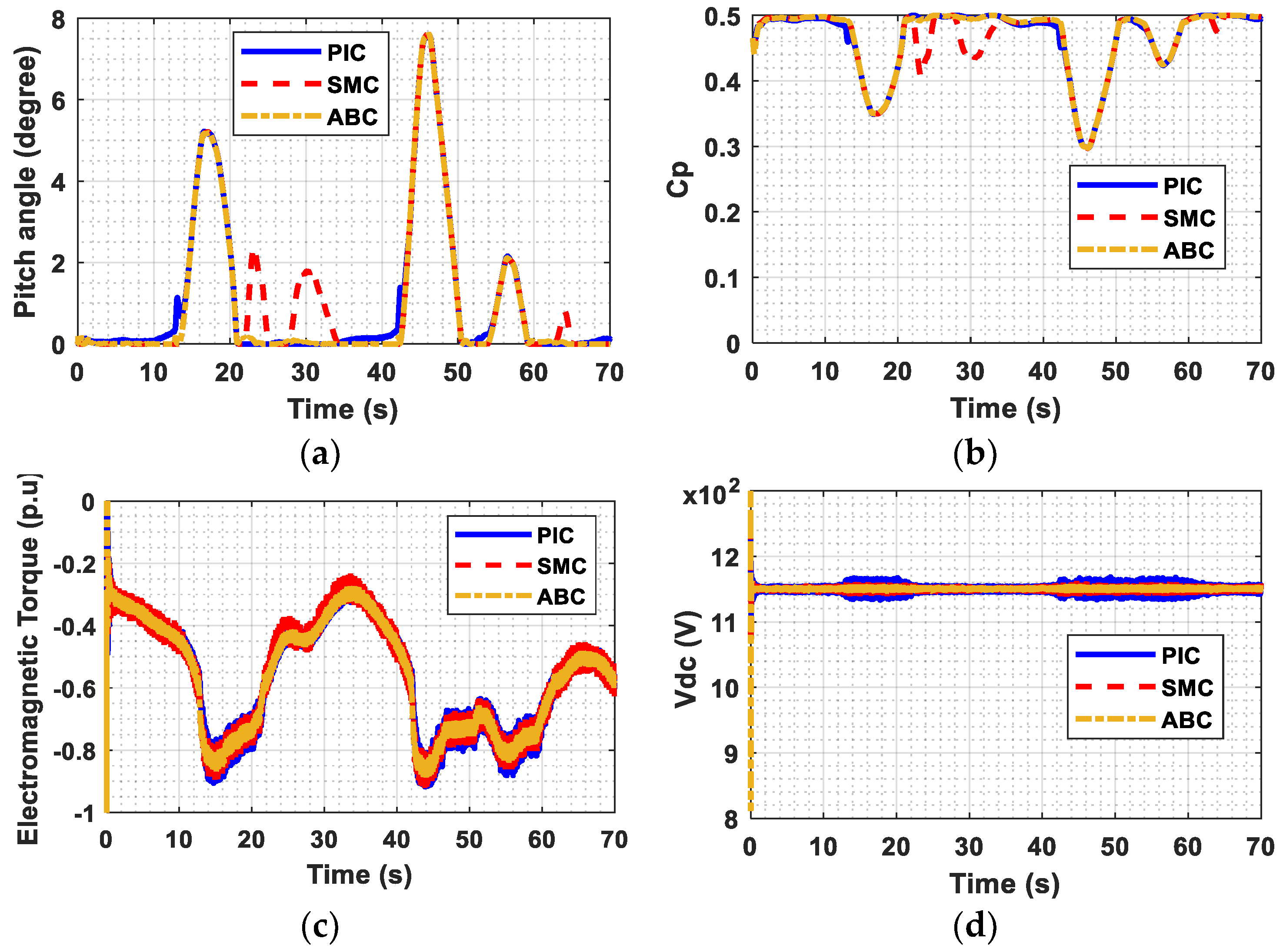
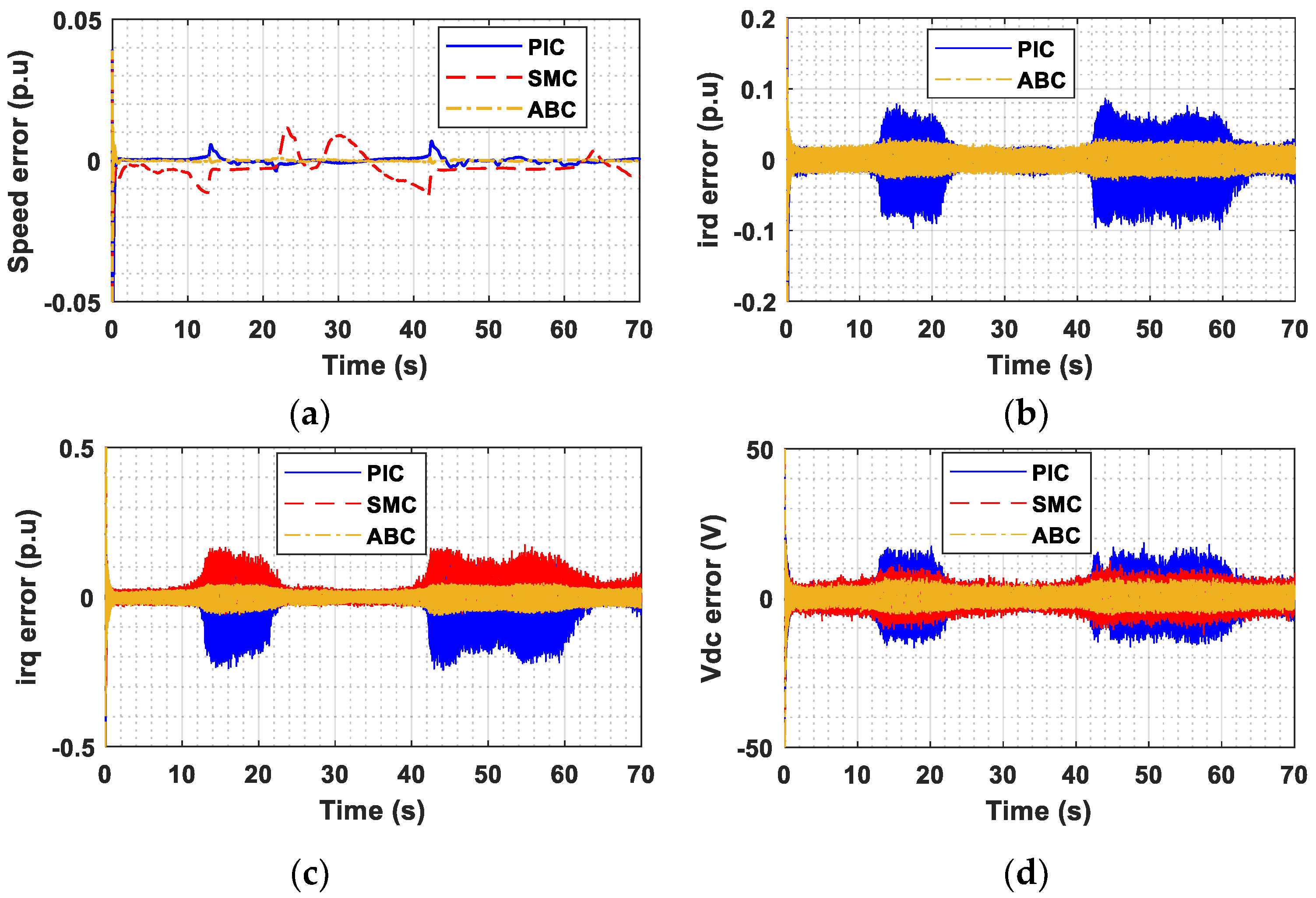
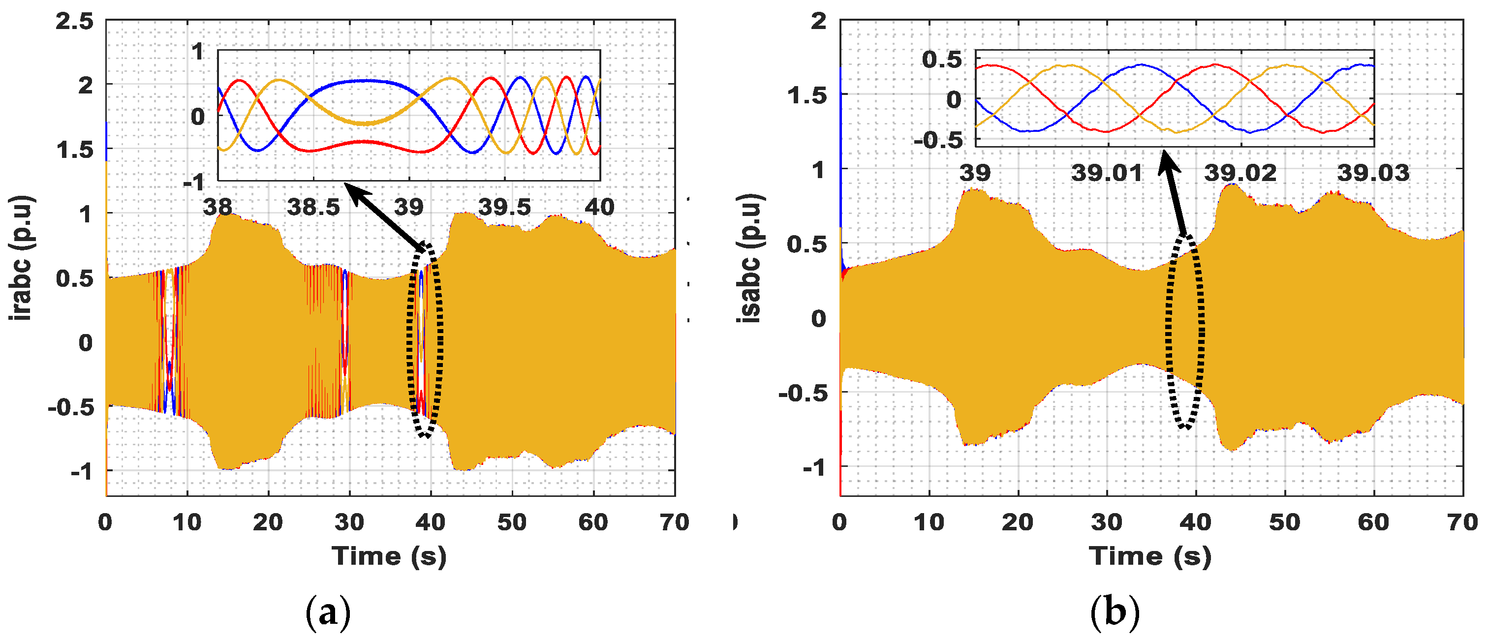
4. Simulation Results
5. Conclusions
Author Contributions
Funding
Institutional Review Board Statement
Informed Consent Statement
Data Availability Statement
Conflicts of Interest
Abbreviation
| Turbine Power | |
| , | Efficiency and maximum efficiency |
| , | Tip Speed Ratio (TSR) and best TSR |
| 𝛽 | Blade angle of inclination (pitch) |
| 𝜌 | Air Density |
| Area of circle created by rotating turbine blades | |
| 𝑣,𝑣𝑒𝑠𝑡 | Actual and estimated wind speeds |
| , | turbine and rotor speed |
| Length of turbine blade | |
| , | turbine torque |
| Gear ratio | |
| Mechanical Torque | |
| Electromagnetic Torque | |
| Shaft stiffness and damping constant | |
| number of machine pole pairs | |
| , | Stator current d and q components |
| , | Rotor current d and q components |
| , | Stator flux d and q components |
| , | Rotor flux d and q components |
| , | Slip speed and angular velocity of stator current |
| , | Controller constants |
| , | Inertials of turbine and generator |
| , | Stator voltage d and q components |
| , | Rotor voltage d and q components |
| , | Resistances of stator and rotor windings |
| , | Self-inductances of rotor and stator |
| Mutual inductance | |
| , | Stator Active and Reactive Power |
Appendix A

| Parameters and Values | |
|---|---|
| Wind turbine | Vmin = 3 (m.s−1), Vn = 12 (m.s−1), Vmax = 25 (m.s−1), Pn = 1.5 (MW) |
| Power coefficient | c1 = 0.6450; c2 = 116; c3 = 0.4; c4 = 5; c5 = 21; c6 = 0.00912; c7 = 0.08; c8 = 0.035 |
| DFIG | Rated power 1.5 (MW); Rotor leakage inductance 0.16 (p.u); Rated stator voltage 690 (V); Mutual inductance 2.9 (p.u); Lumped inertia constant 4.32 (s); DC-Link voltage 1150 (V) Friction factor 0.01 (p.u), Pole pairs 3; Stator leakage inductance 0.18 (p.u); Stator resistance 0.023 (p.u); Rotor resistance 0.016 (p.u) |
| PIC | ; ; ; ; ; ); Pitch power control k = 200 |
| SMC | ; ; |
| ABC | ; ; ; ; ; ; |
References
- Chojaa, H.; Derouich, A.; Chehaidia, S.E.; Zamzoum, O.; Taoussi, M.; Elouatouat, H. Integral sliding mode control for DFIG based WECS with MPPT based on artificial neural network under a real wind profile. Energy Rep. 2021, 7, 4809–4824. [Google Scholar] [CrossRef]
- Chehaidia, S.E.; Abderezzak, A.; Kherfane, H.; Boukhezzar, B.; Cherif, H. An improved machine learning techniques fusion algorithm for controls advanced research turbine (Cart) power coefficient estimation. UPB Sci. Bull. C 2020, 82, 279–292. [Google Scholar]
- El Mourabit, Y.; Derouich, A.; Allouhi, A.; El Ghzizal, A.; El Ouanjli, N.; Zamzoumyes, O. Sustainable production of wind energy in the main Morocco’s sites using permanent magnet synchronous generators. Int. Trans. Electr. Energy Syst. 2020, 30, e12390. [Google Scholar] [CrossRef]
- El-Naggar, M.F.; Mosaad, M.I.; Hasanien, H.M.; AbdulFattah, T.A.; Bendary, A.F. Elephant herding algorithm-based optimal PI controller for LVRT enhancement of wind energy conversion systems. Ain Shams Eng. J. 2021, 12, 599–608. [Google Scholar] [CrossRef]
- Mossad, M.I.; Sabiha, N.A.; Abu-Siada, A.; Taha, I.B.M. Application of Superconductors to Suppress Ferroresonance Overvoltage in DFIG-WECS. IEEE Trans. Energy Convers. 2021, 37, 766–777. [Google Scholar] [CrossRef]
- Hamane, B.; Doumbia, M.L.; Bouhamida, M.; Draou, A.; Chaoui, H.; Benghanem, M. Comparative study of PI, RST, sliding mode and fuzzy supervisory controllers for DFIG based wind energy conversion system. Int. J. Renew. Energy Res. 2015, 5, 1174–1185. [Google Scholar]
- Li, P.; Xiong, L.; Wu, F.; Ma, M.; Wang, J. Sliding mode controller based on feedback linearization for damping of sub-synchronous control interaction in DFIG-based wind power plants. Int. J. Electr. Power Energy Syst. 2019, 107, 239–250. [Google Scholar] [CrossRef]
- Kelkoul, B.; Boumediene, A. Stability analysis and study between classical sliding mode control (SMC) and super twisting algorithm (STA) for doubly fed induction generator (DFIG) under wind turbine. Energy 2021, 214, 118871. [Google Scholar] [CrossRef]
- Chojaa, H.; Derouich, A.; Bourkhime, Y.; Chetouani, E.; Meghni, B.; Chehaidia, S.E.; Yessef, M. Comparative Study of MPPT Controllers for a Wind Energy Conversion System. In Lecture Notes on Data Engineering and Communications Technologies; Springer: Singapore, 2022; pp. 300–310. [Google Scholar]
- Jia, C.; Longman, R.W. An adaptive smooth second-order sliding mode repetitive control method with application to a fast periodic stamping system. Syst. Control. Lett. 2021, 151, 104912. [Google Scholar] [CrossRef]
- Li, P.; Xiong, L.; Ma, M.; Huang, S.; Zhu, Z.; Wang, Z. Energy-shaping L2-gain controller for PMSG wind turbine to mitigate subsynchronous interaction. Int. J. Electr. Power Energy Syst. 2022, 135, 107571. [Google Scholar] [CrossRef]
- Ghafouri, M.; Karaagac, U.; Karimi, H.; Jensen, S.; Mahseredjian, J.; Faried, S.O. An LQR controller for damping of subsynchronous interaction in DFIG-based wind farms. IEEE Trans. Power Syst. 2017, 32, 4934–4942. [Google Scholar] [CrossRef]
- Mokhtari, M.; Khazaei, J.; Nazarpour, D. Sub-synchronous resonance damping via doubly fed induction generator. Int. J. Electr. Power Energy Syst. 2013, 53, 876–883. [Google Scholar] [CrossRef]
- Roy, T.K.; Mahmud, M.A. Active power control of three-phase grid-connected solar PV systems using a robust nonlinear adaptive backstepping approach. Sol. Energy 2017, 153, 64–76. [Google Scholar] [CrossRef]
- Adekanle, O.; Guisser, M.; Abdelmounim, E.; Aboulfatah, M. Integral Backstepping controller combined with High Gain Observer for the optimization of grid-connected Doubly-Fed Induction Generator. In Proceedings of the 2017 International Conference on Wireless Technologies, Embedded and Intelligent Systems (WITS), Fez, Morocco, 19–20 April 2017. [Google Scholar]
- Chehaidia, S.E.; Abderezzak, A.; Kherfane, H.; Guersi, N.; Cherif, H.; Boukhezzar, B. Fuzzy gain scheduling of PI torque controller to capture the maximum power from variable speed wind turbines. In Proceedings of the 2020 IEEE 2nd International Conference on Electronics Control, Optimization and Computer Science (ICECOCS), Kenitra, Morocco, 2–3 December 2020. [Google Scholar]
- Karad, S.; Thakur, R. Recent trends of control strategies for doubly fed induction generator based wind turbine systems: A comparative review. Arch. Comput. Methods Eng. 2021, 28, 15–29. [Google Scholar] [CrossRef]
- Yunus, A.M.S.; Abu-Siada, A.; Mosaad, M.I.; Albalawi, H.; Aljohani, M.; Jin, J.X. Application of SMES Technology in Improving the Performance of a DFIG-WECS Connected to a Weak Grid. IEEE Access 2021, 9, 124541–124548. [Google Scholar] [CrossRef]
- Hamid, C.; Derouich, A.; Hallabi, T.; Zamzoum, O.; Taoussi, M.; Rhaili, S.; Boulkhrachef, O. Performance improvement of the variable speed wind turbine driving a DFIG using nonlinear control strategies. Int. J. Power Electron. Drive Syst. 2021, 12, 2470. [Google Scholar] [CrossRef]
- Tiwari, R.; Babu, N.R. Recent developments of control strategies for wind energy conversion system. Renew. Sustain. Energy Rev. 2016, 66, 268–285. [Google Scholar] [CrossRef]
- Poller, M.A. Doubly-fed induction machine models for stability assessment of wind farms. In Proceedings of the Power Tech Conference Proceedings, Bologna, Italy, 23–26 June 2003. [Google Scholar]
- Chehaidia, S.E.; Kherfane, H.; Cherif, H.; Abderrezak, A.; Chojaa, H.; Kadi, L.; Boukhezzar, B.; Taoussi, M. An Improved Supervised Fuzzy PI Collective Pitch Angle Control for Wind Turbine Load Mitigation. In Digital Technologies and Applications; Springer International Publishing: Cham, Switzerland, 2022. [Google Scholar]
- Lan, J.; Patton, R.J.; Zhu, X. Fault-tolerant wind turbine pitch control using adaptive sliding mode estimation. Renew. Energy 2018, 116, 219–231. [Google Scholar] [CrossRef]
- van Solingen, E.; Fleming, P.A.; Scholbrock, A.; van Wingerden, J.W. Field testing of linear individual pitch control on the two-bladed controls advanced research turbine. Wind Energy 2016, 19, 421–436. [Google Scholar] [CrossRef]
- Abdullah, M.A.; Yatim, A.H.M.; Tan, C.W.; Saidur, R. A review of maximum power point tracking algorithms for wind energy systems. Renew. Sustain. Energy Rev. 2012, 16, 3220–3227. [Google Scholar] [CrossRef]
- Mousa, H.H.; Youssef, A.-R.; Mohamed, E.E. State of the art perturb and observe MPPT algorithms based wind energy conversion systems: A technology review. Int. J. Electr. Power Energy Syst. 2021, 126, 106598. [Google Scholar] [CrossRef]
- Gaillard, A. Système éolien basé sur une MADA: Contribution à l’étude de la qualité de l’énergie électrique et de la continuité de service. Ph.D. Thesis, Université Henri Poincaré-Nancy 1, Nancy, France, 2010. [Google Scholar]
- Kumar, D.; Chatterjee, K. A review of conventional and advanced MPPT algorithms for wind energy systems. Renew. Sustain. Energy Rev. 2016, 55, 957–970. [Google Scholar] [CrossRef]
- Yaakoubi, A.; Amhaimar, L.; Attari, K.; Harrak, M.; EL Halaoui, M.; Asselman, A. Non-linear and intelligent maximum power point tracking strategies for small size wind turbines: Performance analysis and comparison. Energy Rep. 2019, 5, 545–554. [Google Scholar] [CrossRef]
- Viveiros, C.; Melício, R.; Igreja, J.; Mendes, V. Supervisory control of a variable speed wind turbine with doubly fed induction generator. Energy Rep. 2015, 1, 89–95. [Google Scholar] [CrossRef]
- Mosaad, M.I.; Abu-Siada, A.; El-Naggar, M.F. Application of superconductors to improve the performance of DFIG-based WECS. IEEE Access 2019, 7, 103760–103769. [Google Scholar] [CrossRef]
- Pena, R.; Clare, J.; Asher, G. Vector control of a variable speed doubly-fed induction machine for wind generation systems. Epe J. 1996, 6, 60–67. [Google Scholar] [CrossRef]
- Shang, J.; Nian, X.; Liu, K. Air gap field-oriented vector control strategy for high-power electrically excited synchronous motor based on full-order flux linkage observer. Sci. Res. Essays 2014, 9, 367–373. [Google Scholar]
- Srirattanawichaikul, W.; Premrudeepreechacharn, S.; Kumsuwan, Y. A comparative study of vector control strategies for rotor-side converter of DFIG wind energy systems. In Proceedings of the 2016 13th International Conference on Electrical Engineering/Electronics, Computer, Telecommunications and Information Technology (ECTI-CON), Chiang Mai, Thailand, 28 June–1 July 2016. [Google Scholar]
- Ebrahimkhani, S. Robust fractional order sliding mode control of doubly-fed induction generator (DFIG)-based wind turbines. ISA Trans. 2016, 63, 343–354. [Google Scholar] [CrossRef]
- Hamid, C.; Derouich, A.; Taoussi, M.; Zamzoum, O.; Hanafi, A. An improved performance variable speed wind turbine driving a doubly fed induction generator using sliding mode strategy. In Proceedings of the 2020 IEEE 2nd International Conference on Electronics, Control, Optimization and Computer Science (ICECOCS), Kenitra, Morocco, 2–3 December 2020. [Google Scholar]
- Cai, G.; Liu, C.; Yang, D. Rotor current control for a doubly-fed induction generator using a novel nonlinear robust control approach based on extended state observer–backstepping. Trans. Inst. Meas. Control. 2015, 37, 494–504. [Google Scholar] [CrossRef]
- Belmokhtar, K.; Doumbia, M.L.; Agbossou, K. Novel fuzzy logic based sensorless maximum power point tracking strategy for wind turbine systems driven DFIG (doubly-fed induction generator). Energy 2014, 76, 679–693. [Google Scholar] [CrossRef]
- Adekanle, O.S.; Guisser, M.; Abdelmounim, E.; Aboulfatah, M. Robust integral backstepping control of doubly fed induction generator under parameter variation. Int. Rev. Autom. Control 2017, 10, 178–185. [Google Scholar] [CrossRef]
- Abo-Khalil, A.G.; Alyami, S.; Sayed, K.; Alhejji, A. Dynamic Modeling of Wind Turbines Based on Estimated Wind Speed under Turbulent Conditions. Energies 2019, 12, 1907. [Google Scholar] [CrossRef]
- Hung, Y.-H.; Chen, Y.-W.; Chuang, C.-H.; Hsu, Y.-Y. PSO Self-Tuning Power Controllers for Low Voltage Improvements of an Offshore Wind Farm in Taiwan. Energies 2021, 14, 6670. [Google Scholar] [CrossRef]
- Wu, Y.; Dong, J. Local Stabilization of Continuous-Time T–S Fuzzy Systems with Partly Measurable Premise Variables and Time-Varying Delay. IEEE Trans. Syst. Man Cybern. Syst. 2021, 51, 326–338. [Google Scholar] [CrossRef]
- Mi, Y.; Hao, X.; Liu, Y.; Fu, Y.; Wang, C.; Wang, P.; Loh, P.C. Sliding mode load frequency control for multi-area time-delay power system with wind power integration. IET Gener. Transm. Distrib. 2017, 11, 4644–4653. [Google Scholar] [CrossRef]


| Partial Load | Pitch Activated | |||||
|---|---|---|---|---|---|---|
| PIC | SMC | ABC | PIC | SMC | ABC | |
| Generator speed | 3.54.10−3 (p.u) | 0.012 (p.u) | 10−3 (p.u) | 2.10−3 (p.u) | 2.10−3 (p.u) | 2.10−4 (p.u) |
| DC-link voltage | 5.7 (V) | 7 (V) | 4 (V) | 17 (V) | 10 (V) | 5 (V) |
| Electromagnetic Torque | 0.0225 (p.u) | 0.0415 (p.u) | 0.02 (p.u) | 0.0525 (p.u) | 0.0475 (p.u) | 0.0225 (p.u) |
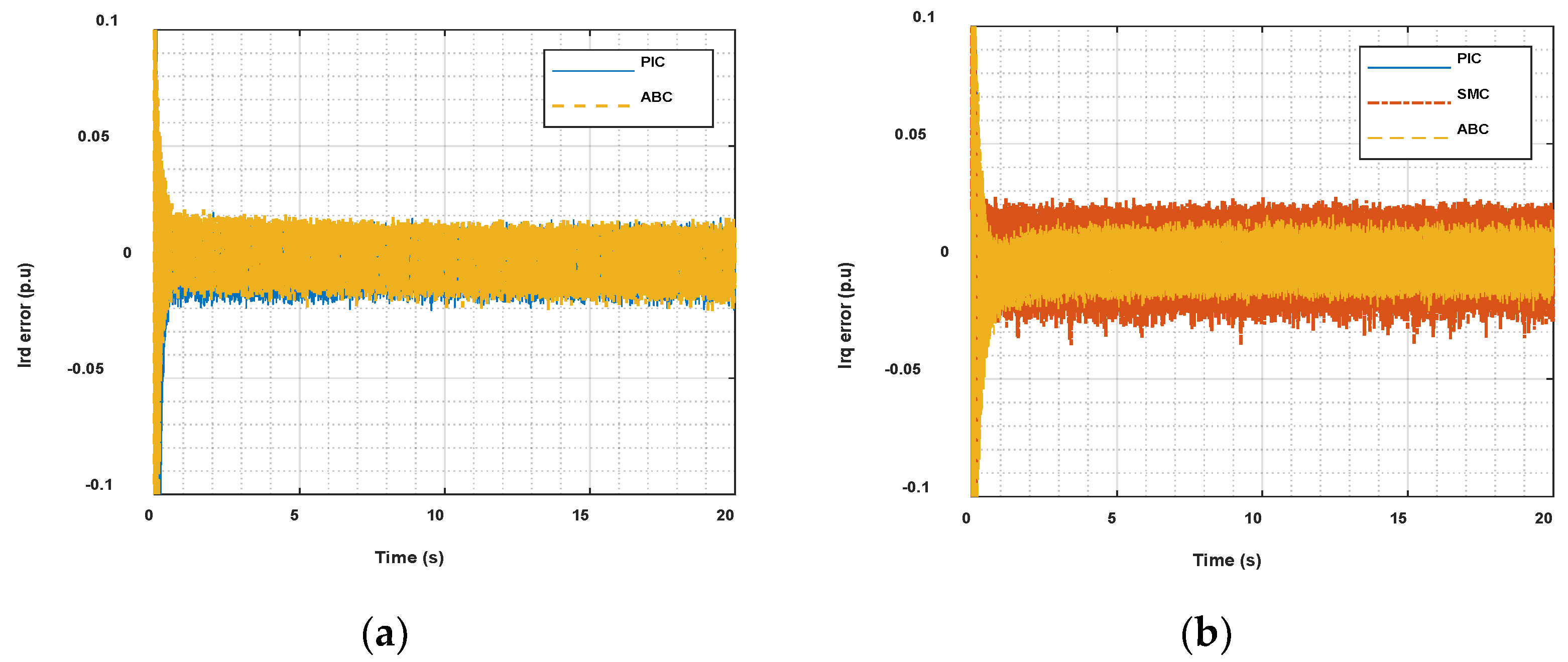
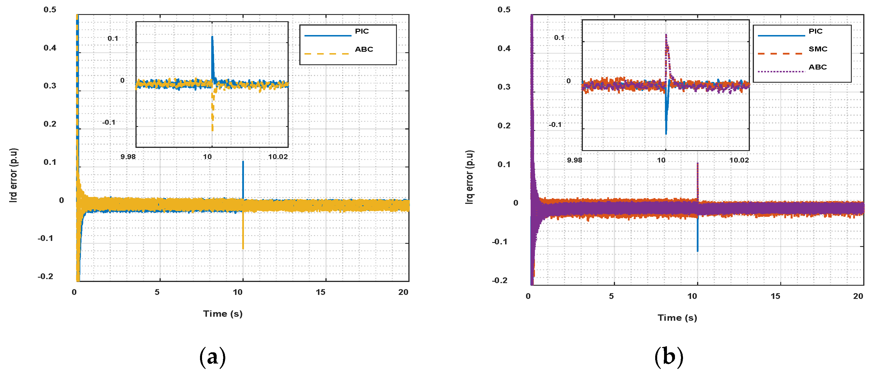
| D-axis rotor current | 0.001 (p.u) | 0.001 (p.u) | 0.09 (p.u) | 0.01 (p.u) | ||
| Q-axis rotor current | 0.015 (p.u) | 0.02 (p.u) | 0.019 (p.u) | 0.24 (p.u) | 0.16 (p.u) | 0.02 (p.u) |
| PIC | SMC | ABC | |
|---|---|---|---|
| Generator speed | 9.141 | 9.141 | 0.4194 |
| DC-link voltage | 6305 | 4403 | 3126 |
| D-axis rotor current | 32.34 | 12.64 | |
| Q-axis rotor current | 76.71 | 41.69 | 26.67 |
Publisher’s Note: MDPI stays neutral with regard to jurisdictional claims in published maps and institutional affiliations. |
© 2022 by the authors. Licensee MDPI, Basel, Switzerland. This article is an open access article distributed under the terms and conditions of the Creative Commons Attribution (CC BY) license (https://creativecommons.org/licenses/by/4.0/).
Share and Cite
Chojaa, H.; Derouich, A.; Taoussi, M.; Chehaidia, S.E.; Zamzoum, O.; Mosaad, M.I.; Alhejji, A.; Yessef, M. Nonlinear Control Strategies for Enhancing the Performance of DFIG-Based WECS under a Real Wind Profile. Energies 2022, 15, 6650. https://doi.org/10.3390/en15186650
Chojaa H, Derouich A, Taoussi M, Chehaidia SE, Zamzoum O, Mosaad MI, Alhejji A, Yessef M. Nonlinear Control Strategies for Enhancing the Performance of DFIG-Based WECS under a Real Wind Profile. Energies. 2022; 15(18):6650. https://doi.org/10.3390/en15186650
Chicago/Turabian StyleChojaa, Hamid, Aziz Derouich, Mohammed Taoussi, Seif Eddine Chehaidia, Othmane Zamzoum, Mohamed I. Mosaad, Ayman Alhejji, and Mourad Yessef. 2022. "Nonlinear Control Strategies for Enhancing the Performance of DFIG-Based WECS under a Real Wind Profile" Energies 15, no. 18: 6650. https://doi.org/10.3390/en15186650