Article

Energy Performance Assessment of a Novel Solar Poly-Generation System Using Various ORC Working Fluids in Residential Buildings

1
Department of Applied Mechanical Engineering, College of Applied Engineering, Muzahimiyah Branch, King Saud University, Riyadh 11421, Saudi Arabia
2
Department of Mechanical Engineering, Benha Faculty of Engineering, Benha University, Benha 13511, Egypt
3
Department of Mechanical and Materials Engineering, Faculty of Engineering, University of Jeddah, Jeddah 21589, Saudi Arabia
4
Department of Mechanical Power Engineering, Faculty of Engineering, Mansoura University, El-Mansoura 35516, Egypt
5
Mechanical Engineering Department, College of Engineering, Najran University, Najran 61441, Saudi Arabia
6
Department of Chemical Engineering, College of Engineering at Yanbu, Taibah University, Yanbu Al-Bahr 41911, Saudi Arabia
7
Department of Mechanical Engineering, Faculty of Engineering at Shoubra, Benha University, Cairo 11629, Egypt
8
Department of Mechanical Engineering, College of Engineering at Yanbu, Taibah University, Yanbu Al-Bahr 41911, Saudi Arabia
*
Authors to whom correspondence should be addressed.
Energies 2022, 15(21), 8286; https://doi.org/10.3390/en15218286
Submission received: 17 October 2022 / Revised: 28 October 2022 / Accepted: 3 November 2022 / Published: 6 November 2022

Abstract

:
Poly-generation systems are an exciting new technology that provide an alternative to separating existing energy production methods in buildings. A poly-generation system enables the efficient simultaneous production of heating, cooling, fresh water, and electricity, resulting in many technological, economic, energy recovery, and environmental advantages. This study numerically investigates three proposed novel solar-driven poly-generation systems (BS, IS-I, and IS-II) integrated with organic Rankine cycle (ORC), humidification-dehumidification desalination system (HDH), and desiccant cooling system (DCS) with different heat recovery system arrangements. The suggested systems supply residential structures with energy, space conditioning, domestic heating, and fresh water. The effects of system operating circumstances on productivity and performance characteristics and several organic working fluid types (n-octane, R245fa, R113, isopentane, and toluene) on optimum system performance have been investigated. The results show that (i) the average enhancement percentage of TGOR using integrated poly-generation systems over the separated ones is 68.5%, 68.5%, and 95.5% for BS, IS-I, and IS-II systems, respectively; (ii) when comparing the three systems, the IS-I system outperforms the other systems (BS & IS-II); and (iii) the maximum values of Wnet, mfresh, Qcooling, and Qheating, obtained for different proposed systems using n-octane are 102 kW (all systems), 214.7 kg/h (IS-II), 29.94 kW (IS-II), and 225.6 kW (IS-I); (iv) R113 has the highest TGOR of 0.6924 (IS-I) compared to other organic fluids. (v) The improvements in W n e t , m f r e s h , Q c o o l i n g and Q h e a t i n g with using toluene instead of R113 at tf1 = 40 °C are 177.5%, 105.8%, 389.25%, and 79%, respectively.

1. Introduction

Renewable poly-generation technology is a possible alternative to conventional energy production. It is useful for small- and medium-sized construction systems. It has economic, environmental, and energy recovery benefits. Increasing industrialization and population have underlined the need for adequate energy, freshwater, and cooling [1]. Renewable energy sources are a long-term solution for building energy, freshwater, and cooling/heating demands. Limited energy sources and global warming threaten the future sustainability of energy production. Therefore, creating more energy-efficient and environmentally friendly technology is crucial. Hybrid systems using renewable energy sources may reduce fossil fuel consumption and CO2 emissions [2,3]. Due to its nonpolluting nature and endless supply, solar energy has gained favor.

1.1. ORC Hybrid/Co-Generation Systems

Building co-generation systems that provide electricity and distilled water have been suggested. Additionally, renewable resources were prioritized. The ORC may use this option from several sources with a wide range of temperatures and renewable energy [4,5]. When a thermal desalination system is coupled to an ORC, it uses thermal energy from internal ORC flows or waste heat, increasing overall system efficiency [6,7]. In certain instances [8,9,10], ORC systems were combined with HDH water desalination systems to provide electricity and freshwater.
A desiccant air conditioner is used to battle rising temperatures without releasing chlorofluorocarbons. A hybrid system combining air cooling, desalination, and renewable energy reduced electricity. Other studies [11,12,13] connected air conditioning and refrigeration systems with HDH water desalination systems to offer a hybrid cooling and freshwater system. System configurations, operational factors, and geometric properties were studied.
Liu et al. [14] developed a hybrid energy supply system that combines GEHPs and ORCs to heat, cool, distribute hot water, and produce electricity for buildings. R245fa, R152a, and R123 are ORCs. According to the study, gas engine waste heat uses 55% of energy. R123 has the best ORC thermal and exergy efficiency (11.84% and 54.24%).

1.2. Tri-Generation/Poly-Generation Systems Integrated with ORC

Tri-generation/poly-generation approaches and technologies may boost global energy efficiency while increasing renewable energy sources, decreasing CO2 emissions, and minimizing electrical system overloads and blackouts [15,16]. Tri-generation is used in buildings, businesses, and manufacturing [17]. Few scholars have modelled renewable energy tri-generation systems that produce electricity, cooling/heating, and freshwater. Zhang et al. [18] explored a tri-generation system for hot water, electricity, and chilled water. They simulated and studied the tri-generation system’s performance to establish operational parameters. Maraver et al. [19] evaluated biomass energy, water, cooling, and heat systems. Their intended poly-generation system comprises an ORC engine, MED plant, and LBSE chiller. The heat released in the ORC condenser for desalination diminishes primary energy savings relative to earlier systems and electric efficiency with each fluid. With the aid of the EES program, Tzivanidis and Bellos [20] produced a mathematical model for the energetic and financial analysis of three alternative solar-driven tri-generation systems that can be used in buildings with high energy requirements (e.g., hospitals or commercial buildings). Different organic Rankine cycles (ORC) and heat pumps are practically combined in the configurations under examination. The energy efficiency of the three systems was 78.17%, 43.30%, and 37.45%, respectively, while the exergy efficiency was 15.94%, 13.08%, and 12.25%, respectively.
Calise et al. [21] explored a solar geothermal poly-generation plant to offer electric, thermal, cooling, and freshwater to a small settlement. The integrated system incorporates a geothermal ORC and a solar field. Geothermal fluid warms a desalination unit. V. Zare [22] examined thermodynamically two geothermal tri-generation systems (one using an ORC and the other using a Kalina cycle). ORC and Kalina cycles are connected to a LiBr/water absorption chiller and a water heater. Rostamzadeh et al. [23] presented two more efficient tri-generation systems for combined cooling, heating, and power (CCHP) based on the ORC and KC systems. The proposed systems were evaluated in terms of thermodynamics and exergoeconomics. The ORC- and KC-based micro-CCHP systems’ optimal thermal efficiencies were determined at 76.54% and 77.32%, respectively. By combining a waste heat-powered ORC with vapor compression–absorption cascade refrigeration, Patela et al. [24] introduced a tri-generation system. They also thermo-economically compared the hybrid unit to a standalone vapor compression system. The proposed system outperformed the standalone vapor compression, produced cooling at −20 °C, and processed heating at 84 °C and 10 KW of electricity while saving USD 12,078 annually.
Gholizadeh et al. [25] built a biogas-powered tri-generation system for electricity, cooling, and drinking water. The system incorporates ORC, ECC, HDH, and gas turbine (GT). The system’s optimization improves net power, cooling, TGOR, and energy efficiency by 2.58, 22.69, 14.04, and 13.26%. Ghorab et al. [26] improved a household hybrid renewable energy system’s annual energy performance. The multi-module hybrid system includes a ground-air heat exchanger, photovoltaic thermal panels, and an air-to-water heat pump (AWHP). The developed system met the building’s heating and cooling needs all year. During heating and cooling seasons, the ground source heat exchanger contributed 21.3% and 26.3% of the energy. Li et al. [27] describe a geothermal-driven tri-generation architecture with cascade power and CO2 cooling. The geothermal-powered cascade system incorporates an MKC, an ORC, and an LNG subsystem. The system has 451.8 kW net power, 297.8 kW cooling rate, and a 2.274 kg/h hydrogen rate. Recently, a tri-generation system for generating electricity, cooling, and desalinating water has been analyzed numerically by Fouda et al. [28]. The suggested system consists of different cycles; an ORC, a humidification and dehumidification (HDH) water desalination system, a desiccant cooling system (DCS), and a solar system (including evacuated tube collectors and a thermal energy storage unit). The proposed tri-generation system can offer 104.5 kW of electrical power, 72.37 kg/h of freshwater capacity, 25.48 kW of space cooling capacity, and a EUF of 0.2643.
The literature review revealed that several co-generation systems for power, fresh water, and cooling load were integrated with MED/SRC/ARS and HDH/ORC/ECC, as well as a few tri-generation systems for power, fresh water, and cooling load using CPVT (combining concentrating photovoltaic and thermal solar collectors) and biogas, biomass boilers, and geothermal wells. So far, however, multigenerational systems have received less attention. Therefore, a novel multigeneration setup based on an ORC, DCS, and HDH unit is designed for small- and medium-sized structures to provide electricity, space cooling/domestic heating, and potable water. ORC power production works well at low operating temperatures [29]. Traditional air conditioners release pollutants, such as chlorofluorocarbons into the air, whereas desiccant air conditioners do not. As a result, the authors are driven to investigate the design, operation, and performance evaluation of multigeneration systems that provide small- and medium-sized houses with solar-powered, continuously available electricity, fresh water, and space cooling/domestic heating.
As far as the authors know, no prior studies of such complex systems have been conducted. This study proposes and thermodynamically assesses three different poly-generation systems: ORC, HDH, and DCS. Thermodynamic and parametric analyses are used to examine the effect on the systems’ output and performance metrics. There is one “basic” system [28] and two “enhanced” systems with different heat recovery technologies, all of which are compared to the “basic” system to see which one is the most efficient. EES (engineering equation solver) is used for a thermodynamic analysis and simulation of the system’s cycles. The article will provide the following criteria for evaluating the proposed systems’ designs: (i) extensive energy mathematical modeling; (ii) how changing settings for the systems’ operations affect their efficiency and effectiveness; (iii) examining the strengths and weaknesses of the suggested systems concerning the original setup; (iv) how different kinds of organic fluids affect the system’s peak efficiency. Researchers, solar poly-generation developers, power plant designers, and investors should all benefit from the proposed integrated ORC, HDH, and DCS poly-generation systems’ findings due to the systems’ economic and environmental viability for producing electricity, space cooling, domestic heating, and freshwater for end users, especially in small- and medium-scale buildings.

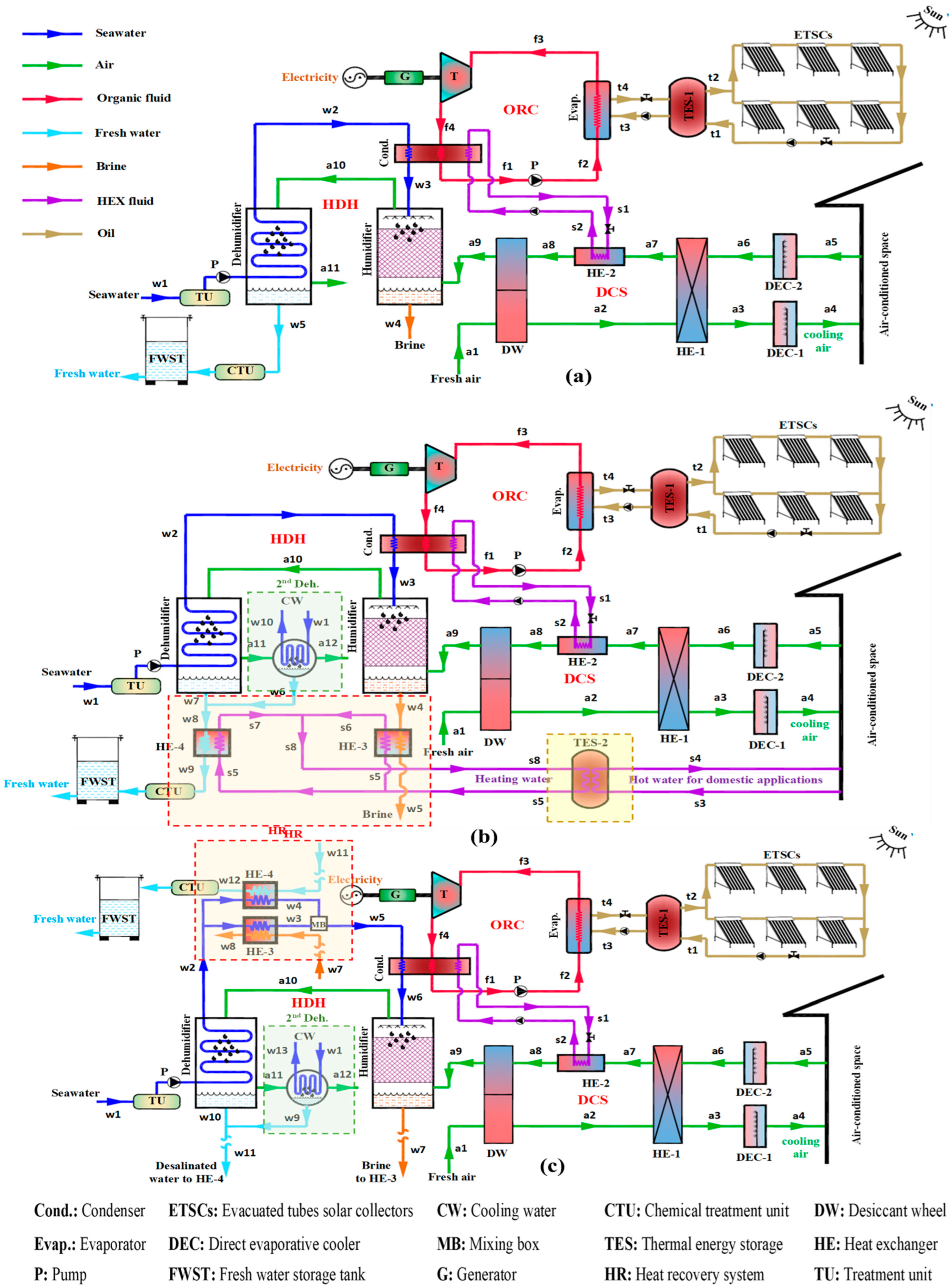
2. Systems Description

For an overview of the three planned solar-powered poly-generation systems, each with its heat recovery and energy storage components, see Figure 1.
The proposed systems couple solar ORC with a DCS and a HDH desalination unit to provide energy, space cooling/domestic heating, and potable water. An evacuated-tube solar collector and a thermal storage tank make up the solar system. A thermal oil (therminol-VP1) is used as the working fluid for the solar field loop due to its ability to remain in the liquid phase at temperatures up to 400 °C [30]. The three systems under consideration are the baseline “basic system” (BS), the “enhanced system-I” (IS-I), and the “improved system-II” (IS-II). As shown in Figure 1, the BS can produce power, space cooling, and potable water (a). Two of the cycles in the system are closed (the solar cycle and the ORC), while the other two are open (the air cycle and water cycle).
Solar collectors charge the TES-1 tank during the day (state points t1 and t2) and are then used to meet the system’s constant energy demand at night (state point t2) through the ORC evaporator (state points t3 and t4). The thermal oil is used to superheat the ORC fluid via the ORC cycle, evaporating and expanding through the turbine, all while powering a linked generator. By condensing the ORC fluid as it leaves the turbine at (f4), the waste heat from the DCS and HDH units may be recovered to maintain a constant temperature at state points (a8) and (w3). To finish the cycle, the ORC liquid is piped to (f2) before being sent back to the evaporator.
At (a1), process air is drawn into the desiccant wheel (DW), where it is heated to (a2) and dehumidified; after leaving the DW, the air is cooled to (a3) in the heat exchanger (HE-1). Then, at (a4), the process air is cooled and humidified in the direct evaporative cooler (DEC-1) before it is released into the conditioned area. At (a5), the air is drawn back from the conditioned environment and sent through the DEC-2, which is cooled and humidified before being released at (a6). Afterward, the recirculated air is heated utilizing a heat exchanger (HE-1) (a7). After reaching the required regeneration temperature (a8), the regeneration air is cooled and humidified in the DW (reactivation portion) by recovering some of the waste heat from the ORC condenser (a9). The HDH system concludes with a humidifier, which constantly draws in the regeneration air from the DW and chills it to (a10). Then, it sends it to the dehumidifier, where it is dehumidified at a higher temperature (a11).
Desalinated water is produced in the water cycle when seawater at (w1) is pumped through the water treatment unit (TU) to remove turbidity, bacterial content, and total dissolved solids, which cause fouling and scaling in the tubes. The water then travels through the dehumidifier coil to remove moisture from the humid air generated by the humidifier (w5). After going through a chemical treatment unit (CTU), the desalinated water is transformed into fresh/potable water with a salinity of 500 parts per thousand (ppm), which is the World Health Organization’s (WHO) recommended standard. The seawater from the DCS’s DW is warmed to provide moisture to the air (w2). After that, it passes through an ORC condenser, where part of the waste heat is recovered to raise the temperature to (w3), and last, it passes via a humidifier. The incoming air carries some of the clean water’s evaporation to the dehumidifier, while the remainder is released as brine from the humidifier’s outlet (w4).
Figure 1 depicts the enhanced system-I (IS-I) (b). Aside from providing power, the system can also produce potable water and cooling or heating air for residential use. Similar to the BS, this system comprises several interconnected parts that work together to accomplish its goals. Second-stage dehumidification, heat recovery, and a thermal energy storage unit to reuse the recovered heat in residential heating applications are also included in the system upgrade. At (a11) in IS-I, air passes from the first to the second dehumidifier, where its moisture content is reduced even more (a12). The total yield of desalinated water at (w6) is the sum of the desalinated water produced at (w7), and the desalinated water yielded after the first stage of dehumidification has concluded (w8). Then, to reuse most of the wasted heat, household heating water (TES-2) is produced by passing desalinated water (w8) through a brine water recovery system (HRS) to hot water. This contributes to better system optimization and smoother running.
Figure 1 displays the enhanced system-II (IS-II) (c). It can produce electricity, space conditioning, and potable water. This proposal’s heat recovery mechanism and second-stage dehumidifier are identical to those in the (BS) (HR). It is advised that the heat recovered from the brine (w7) and the desalinated water (w11) be used to warm the supply of salt water (w2) before entry into the humidifier. This will boost the HDH system’s ability to humidify the air (w2) effectively. Saltwater exits the IS-first II’s stage dehumidifier at w2, and from there, it is separated into two streams. One of these streams travels via heat exchangers HE-3 and HE-4 to recover heat energy from desalinated water (w11), and the other stream travels via heat exchangers HE-7 and HE-8 to recover heat energy from brine (w7) (mixing of w3 and w4).

3. Mathematical Model and Thermodynamics Analysis

Solar energy is used to study and deploy poly-generation systems for domestic applications, such as water desalination, air conditioning, electricity production, and hot water. The poly-generation system is separated into three subsystems to determine the thermodynamic parameters of subsystems and the overall system performance: ORC, HDH, and DCS. During the simulation model phase, the first and second laws of thermodynamics are applied to each system component.
The following assumptions have been considered in the present model:
  • All system processes are believed to be in a state of equilibrium.
  • The leakage of air/water in system components is disregarded.
  • The kinetic and gravitational energy is not considered.
  • The temperature of the air wet-bulb and the blowdown water exiting the humidifier is the same.
  • The mass flow rate of process air, return air, and water is the same.
  • The efficiency of HE-2 is taken by 100% (ta8 = tw3). The freshwater and air wet-bulb temperatures are the same at the dehumidifier’s outlet.
  • The states of the ORC fluid at the turbine intake are dry-saturated and superheated, depending on the tevap and degree of superheating.
  • The ORC fluid condition at the pump input is saturated liquid based on the condenser pressure.
  • The cold outlet streams from the ORC condenser are assumed to be the same (ts1= tw3) to distribute the condenser capacity on HDH and DCS cycles.
  • The specific power of auxiliary components (power used by fans) is neglected in DCS and HDH systems.
  • Because of its performance and thermodynamic qualities, organic fluid (n-octane) is chosen for the comparative research of the suggested systems [31].
  • Various organic fluids (n-octane, R245fa, R113, isopentane, and toluene) are investigated to determine which delivers the highest system performance (IS-I).
  • The relevant efficiencies for the system components are shown in Table 1 and Table 2.
System productivity is measured in terms of electricity production (Wnet), freshwater productivity (mfresh), space cooling capacity (Qcooling), and home heating capacity (Qheating) in the examined poly-generation systems. The effectiveness of the system is evaluated using several different variables, such as the total gained output ratio (TGOR), the specific total gained energy (STG), the specific total gained energy equivalent cost (STGP), the thermal efficiency of ORC (ORC), the gain output ratio (GORHDH), the coefficient of performance of DCS (COPDCS), the space supply air temperature and humidity ratio (t4 and w4), and the area of solar collectors. All of these variables are taken into consideration (Asolar). In the present poly-generation system, solar energy generates electricity, space cooling capacity, freshwater production, and hot water.

3.1. Organic Rankine Cycle (ORC)

Within the parameter range of the solar energy heat source, the organic working fluid (n-octane, R245fa, R113, isopentane, and toluene) is evaporated using solar energy because of its low boiling temperature and adequate operating pressure. The governing equations (Equations (1)–(11)) for evaporator, condenser, turbine, pump, and ORC thermal efficiency are given based on the energy and mass balance:
Evaporator energy balance
Q E v a p = m O R C ( h f 3 h f 2 )
m O R C ( h f 3 h f 2 ) = m o i l ( h t 3 h t 4 )
η s o l a r = Q E v a p I T , a v g , d a i l y A s o l a r
Here, we use the value I T , a v g , d a i l y = 800 W/m2 from [14] for the daily average total solar intensity. However, the thermal efficiency of an evacuated tube solar collector is, on average, 63.2% each year [34].
Condenser energy balance
Q C o n d = m O R C ( h f 4 h f 1 )
ε c o n d = ( m W ( h w 3 h w 2 ) + m R , a ( h a 8 h a 7 ) m O R C ( h f 4 h f 1 ) )
M R = m O R C m R , a + m w
Turbine power
W t = m O R C ( h f 3 h f 4 ) η t η g
Pump power
W p = m O R C v f 1 ( P f 2 P f 1 ) / η p
W p = m O R C ( h f 2 , a h f 1 )
ORC net power and thermal efficacy
W n e t = W t W p
η O R C = W n e t Q E v a p

3.2. Desiccant Cooling System (DCS)

In this research, the desiccant wheel, the DCS’s central component, is modelled using the framework developed by Panaras et al. [35]. The governing equations and accompanying energy balances for the DCS parts are as follows:
F 1 , i = [ 2865 ( t i + 273.15 ) 1.49 ] + 4.344 [ w i / 1000 ] 0.8624
F 2 , i = [ ( t i + 273.15 ) 1.49 6360 ] 1.127 [ w i / 1000 ] 0.07969
Desiccant wheel’s efficiency
η F 1 = F 1 , 2 F 1 , 1 F 1 , 8 F 1 , 1
η F 2 = F 2 , 2 F 2 , 1 F 2 , 8 F 2 , 1
The efficiencies of the desiccant wheel are at a high level of about η F 1 = 0.05 and η F 2 = 0.95 [36].
Energy and mass balances of the desiccant wheel
m P , a ( h a 2 h a 1 ) = m R , a ( h a 8 h a 9 )
m P , a ( w a 1 w a 2 ) = m R , a ( w a 9 w a 8 )
Heat exchanger
m P , a c p , m a ( t a 2 t a 3 ) = m R , a c p , m a ( t a 7 t a 6 )
ε H E 1 = m P , a c p , m a ( t a 2 t a 3 ) C m i n ( t a 2 t a 6 )
where C m i n = m i n { m P , a c p , m a , m R , a c p , m a } .
Direct evaporative coolers:
η D E C 1 = t a 3 t a 4 t a 3 t a 3 , w b
η D E C 1 = w a 4 w a 3 w a 4 , I d e a l w a 3
η D E C 2 = t a 5 t a 6 t a 5 t a 5 , w b
η D E C 2 = w a 6 w a 5 w a 6 , I d e a l w a 5
Regeneration energy, space cooling capacity, and coefficient of performance
Q i n , D C S = m R , a ( h a 8 h a 7 )
Q c o o l i n g = m P , a ( h a 5 h a 4 )
C O P D C S = Q c o o l i n g Q i n , D C S

3.3. Humidification-Dehumidification Water Desalination System (HDH)

The energy balance of the humidifier is given as
m R , a ( h a 10 h a 9 ) = m w h w 3 m b r i n e h w 4 ( f o r B S & I S I ) ,
m R , a ( h a 10 h a 9 ) = m w h w 6 m b r i n e h w 7 ( f o r I S I I )
where
m b r i n e = m w m m a k e u p
The mass flow rate of makeup water (sea or brackish water) supplied to the system is defined as
m m a k e u p = m R , a ( w a 10 w a 9 )
As indicated by the energy balance and freshwater productivity of the basic system, the principal dehumidifier is
m R , a ( h a 10 h a 11 ) = m w ( h w 2 h w 1 ) + m f r e s h   h w 5
ε d e h 1 = m w c p , w ( t w 2 t w 1 ) c m i n ( t a 10 t w 1 )
m f r e s h ( B S ) = m R , a ( w a 10 w a 11 )
where
h w 5 = c p , w t a 11
C m i n = m i n { m w c p , w , m R , a c p , m a }
Total freshwater production, freshwater productivity from the second dehumidifier, and energy balance for IS-I and IS-II systems are as follows:
m R , a ( h a 11 h a 12 ) = m w ( h w 10 h w 1 ) + m f r e s h I I   h w 6
m f r e s h , I I = m R , a ( w a 11 w a 12 )
m f r e s h ( I S I o r I S I I ) = m f r e s h   ( B S ) + m f r e s h , I I
The gain output ratio (GOR) for the basic and IS-I & IS-II systems is given by
G O R H D H ( B S ) = m f r e s h   ( B S ) h f g m w ( h w 3 h w 2 ) + m R , a ( h a 9 h a 1 )
G O R H D H ( I S I ) = m f r e s h   ( I S I ) h f g m w ( h w 3 h w 2 ) + m R , a ( h a 9 h a 1 )
G O R H D H ( I S I I ) = m f r e s h   ( I S I I ) h f g m w ( h w 6 h w 2 ) + m R , a ( h a 9 h a 1 )

3.4. Hot Water for Domestic Application in IS-I

The effectiveness of heat exchangers 3 & 4 and total domestic heating capacity for system (IS-I) can be calculated as follows:
ε H E 3 = Q h e a t i n g I m b r i n e c p , w ( t w 4 t s 5 )
ε H E 4 = Q h e a t i n g I I m f r e s h ( I S I ) c p , w ( t w 8 t s 5 )
Q h e a t i n g = Q h e a t i n g I + Q   h e a t i n g I I
m f r e s h ( I S I ) c p , w t w 8 = m f r e s h   ( B S ) c p , w t w 7 + m f r e s h , I I   c p , w t w 6

3.5. Air and Water Waste Heat Recovery IS-II

The effectiveness total heat recovery of of heat exchangers 3 & 4 for system (IS-II) can be calculated as follows:
ε H E 3 = m w , 2 c p , w ( t w 3 t w 2 ) m b r i n e c p , w ( t w 7 t w 2 )
ε H E 4 = m w , 1 c p , w ( t w 4 t w 2 ) m f r e s h ( I S I I ) c p , w ( t w 11 t w 2 )
m w c p , w t w 5 = m w , 1 c p , w t w 4 + m w , 2 c p , w t w 3

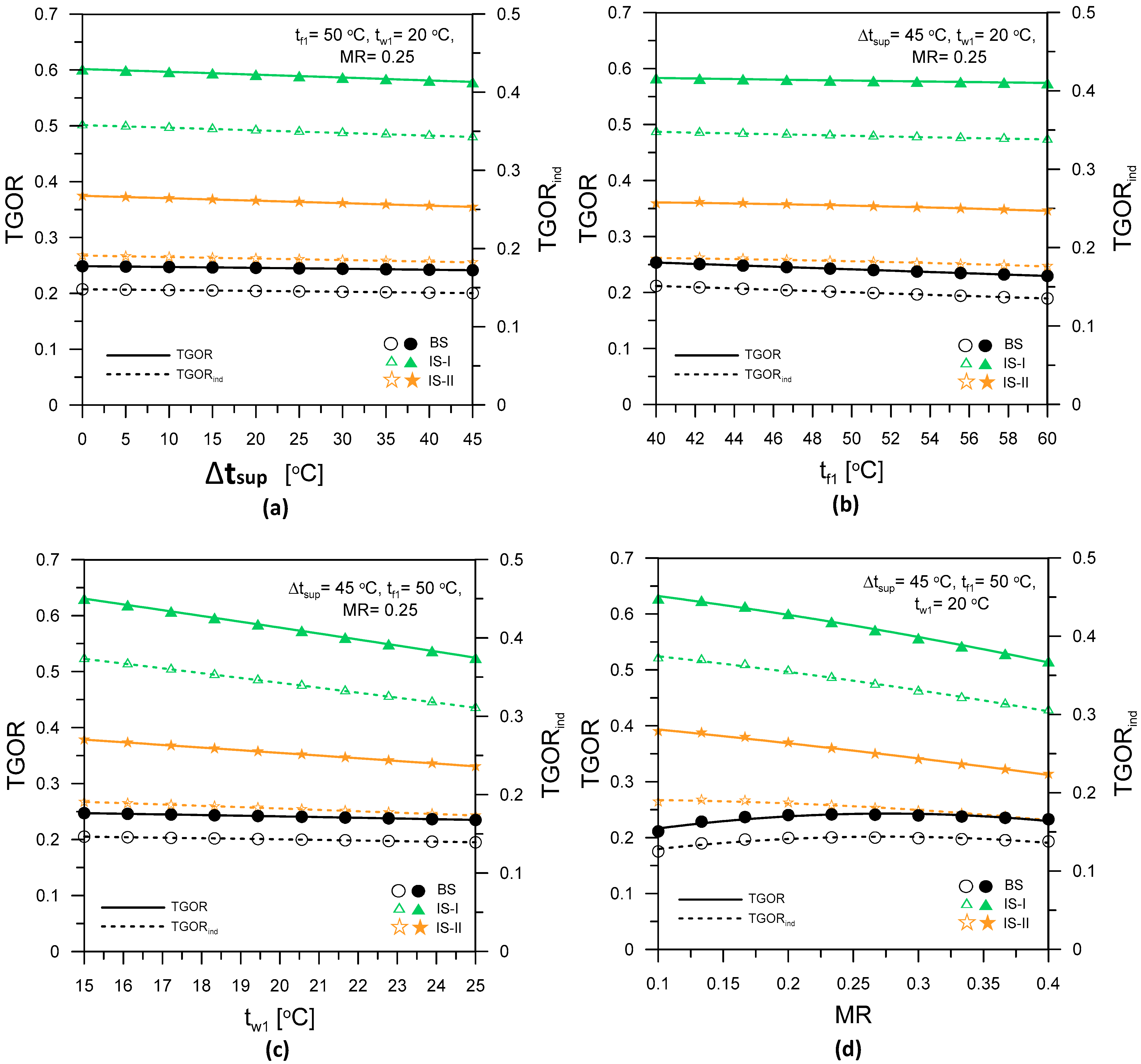
3.6. System Performance Parameters and Evaluation

The suggested basic, IS-I, and IS-II poly-generation systems have the following tri-generation total gained output ratios (TGOR), tri-generation gained output ratio for independent systems (TGORind), specific total gained energy (STG), and specific total gained energy equivalent price (STGP).
T G O R B S = m f r e s h ( B S ) h f g + Q c o o l i n g + W n e t Q E v a p
T G O R B S _ i n d = m f r e s h ( B S ) h f g + Q c o o l i n g + W n e t Q E v a p + m W ( h w 3 h w 2 ) + m R , a ( h a 8 h a 7 )
T G O R I S I = m f r e s h ( I S I ) h f g + Q D o m e s + Q c o o l i n g + W n e t Q E v a p
T G O R I S I _ i n d = m f r e s h ( I S I ) h f g + Q D o m e s + Q c o o l i n g + W n e t Q E v a p + m W ( h w 3 h w 2 ) + m R , a ( h a 8 h a 7 )
T G O R I S I I = m f r e s h ( I S I I ) h f g + Q c o o l i n g + W n e t Q E v a p
T G O R I S I I _ i n d = m f r e s h ( I S I I ) h f g + Q c o o l i n g + W n e t Q E v a p + m W ( h w 3 h w 2 ) + m R , a ( h a 8 h a 7 )
S T G B S = ( m f r e s h ( B S ) h f g + Q c o o l i n g + W n e t ) Δ τ A S C
S T G I S I = ( m f r e s h ( I S I ) h f g + Q h e a t i n g + Q c o o l i n g + W n e t ) Δ τ A S C
S T G I S I I = ( m f r e s h ( I S I I ) h f g + Q c o o l i n g + W n e t ) Δ τ A S C
S T G P B S = [ m f r e s h ( B S ) × W U R + ( Q c o o l i n g + W n e t ) × E U R ] Δ τ
S T G P I S I = [ m f r e s h ( I S I o r I S I I ) × W U R + ( Q D o m e s + Q c o o l i n g + W n e t ) × E U R ] Δ τ
S T G P I S I I = [ m f r e s h ( I S I I ) × W U R + ( Q c o o l i n g + W n e t ) × E U R ] Δ τ
where
Δ τ : daylight time (12 h);
WUR: water unit rate $/kg;
EUR: Energy unit rate $/kWh.
Prices for energy and freshwater units differ from city to city. The current analysis uses average Gulf city energy and water unit pricing of 0.05 $/kWh and 2.5 $/m3 [13,36].
To analyze system performance and conduct comparison studies between the three poly-systems and independent systems, we stated the tri-generation total acquired output ratio increases for basic system (BS), improved system-I (IS-I), and improved system-II (IS-II) as follows:
T G O R i m p = T G O R I S I o r I I T G O R B S T G O R B S
T G O R i m p _ B s _ i n d = T G O R B s T G O R B S _ i n d T G O R B S _ i n d
T G O R i m p _ I S I _ i n d = T G O R I S I T G O R I S I _ i n d T G O R I S I _ i n d
T G O R i m p _ I S I I _ i n d = T G O R I S I I T G O R I S I I _ i n d T G O R I S I I _ i n d
The system governing equations (Equations (1)–(61)) are simulated by using C++ and EES software based on energy and mass balances for all system components to calculate the system performance and productivity parameters for different ranges of design and operating conditions as given in Table 1.

4. Results and Discussion

The present research looks at the performance of three different suggested poly-generation systems (BS, IS-I, and IS-II). It combines solar ORC with DCS and HDH systems to create energy, space cooling, domestic heating, and freshwater for small-/medium-scale structures. The validation of the existing model and comparisons of the suggested systems with the independent, separated systems are described in the following sections. Moreover, the impacts of the controlling parameters (Δtsup, tf1, tw1, and MR) on the systems’ productivities (Wnet, mfresh, Qcooling/Qheating) and the systems’ performance indicators (ηORC, GORHDH, COPDCS, TGOR, STG, and STGP) are investigated, discussed, and evaluated using n-octane as an organic fluid. In addition, system assessment parameters (TGORimp, ta4, and wa4) are also presented. The results of these sections are used to compare the performances of the different systems for the sake of selecting the optimum system configuration. Finally, the impact of varying ORC fluids (n-octane, R245fa, R113, isopentane, and toluene) on the optimum system performance is also studied and discussed.

4.1. Model Validation

To validate the current thermodynamic models and establish their degree of accuracy, we compared the recent work’s results with those described in the literature. The validation of the current thermodynamic models with previously published data in [35,37,38] for the HDH, ORC, and DCS subsystems is shown in Table 3. As demonstrated in Table 3, there is good consistency between the results obtained in this investigation and those previously reported in the literature.

4.2. Systems Comparisons and Assessments

Figure 2 compares the proposed integrated poly-generation systems (BS, IS-I, and IS-II) with separable standalone ones. It displays the total gained output ratio as an overall performance metric for both integrated (TGOR) and independent (TGORind) systems for various ranges of researched parameters (tsup, tf1, tw1, and MR). As shown in Figure 2a–d, the system performance parameters (TGOR, TGORind) of the IS-I system are higher than those of the BS and IS-II systems, while the IS-II system is higher than that of the BS system. Such a trend is the same at any Δtsup, tf1, tw1, or MR. Moreover, the TGOR of the proposed integrated systems is higher than that of the separate independent ones. This observation is similar for all studied systems (BS, IS-I, and IS-II) and at any studied parameter values within the studied ranges. These findings are matched with those obtained and presented by [39]. This is attributed to using waste heat recovery in integrated poly-generation systems, leading to higher overall performance than the separate independent systems. Additionally, as shown in Figure 2a–d, the average enhancement percentage of TGOR using integrated poly-generation systems over the separated ones is 68.5%, 68.5%, and 95.5% for BS, IS-I, and IS-II systems, respectively, within the studied ranges of Δtsup, tf1, tw1, and MR.
Figure 3a–d shows the influence of controlling parameters (Δtsup, tf1, tw1, and MR) on TGORimp for both IS-I and IS-II systems. As shown in Figure 3a, Δtsup has little effect on TGORimp, whereas TGORimp parameter increases with increasing tf1, as shown in Figure 3b, but decreases with increasing tw1 and MR (Figure 3c,d). Additionally, the TGORimp of IS-I is higher than that of IS-II. Moreover, the trend is the same along all ranges of all studied parameters. This is attributed to the higher performance and TGOR of IS-I than IS-II due to the recovery system improvement of system IS-I. IS-I has a maximum TGORimp of 197.4% at Δtsup = 45 °C, tf1 = 50 °C, tw1 = 20 °C, and MR = 0.1.

4.3. Systems’ Productivity and Performance

The impacts of controlling parameters (Δtsup, tf1, tw1, and MR) on the systems’ productivities (Wnet, mfresh, Qcooling) and systems’ performance indicators (ηORC, GORHDH, COPDCS, TGOR, STG, STGP) of the three proposed poly-generation systems (BS, IS-I, and IS-II) are presented in Figure 4 and Figure 5 with different ORC fluids (n-octane, R245fa, R113, isopentane, toluene). Figure 4a–d and Figure 5a–d demonstrate the effect of the superheat degree, Δtsup, on the systems’ productivities and performance at tf1 = 50 °C, tw1 = 20 °C, and MR = 0.25. As shown in Figure 4a–d, the systems’ productivities improve with increasing Δtsup. Such a trend is the same for the three proposed systems with different ORC fluids. This is attributed to the increase in turbine work, solar energy needed, and the heat liberated at the ORC condenser as the turbine inlet temperature increases. This reflects the increase in the solar collectors’ needed area, the air humidification capacity inside the humidifier, and the space cooling capacity. By contrast, the systems’ performance indicators for the three proposed systems at operating conditions are slightly decreased with increasing Δtsup as shown in Figure 5a–d. The heat input to ORC, HDH, and DCS increases with increasing turbine inlet temperature, resulting in a drop in ηORC, GORHDH, and consequently lower TGOR, STG, and STGP. Moreover, increasing the Δtsup has a positive impact on the COPDCS of BS & IS-I systems and an adverse effect on the COPDCS of IS-II system. For all three proposed systems, the solar area, Asolar, increases as Δtsup increases. Increasing the amount of superheat at the turbine inlet requires increasing the solar input heat of the ORC.
Moreover, Figure 4e–h and Figure 5e–h display the effect of tf1 on the systems’ productivities and performance at Δtsup = 45 °C, tw1 = 20 °C and MR = 0.25. The condensing temperature of ORC has an adverse effect on the systems’ productivity and performance. This trend is similar for BS, IS-I, and IS-II with different ORC fluids.
Furthermore, Figure 4i–l and Figure 5i–l at Δtsup = 45 °C, tf1 = 50 °C, and MR = 0.25 show that increasing tw1 has an adverse effect on systems’ productivities (expect Qcooling) and performance. Decreasing mfresh is due to decreasing the air dehumidification capacity through the dehumidifier, which leads to a lower freshwater production rate. Qcooling increases due to increasing the DCS regeneration energy due to lowering the seawater heating energy part that is recovered from the ORC condenser at the same amount of total condenser heat recovered.
Finally, Figure 4m–p and Figure 5m–p show the effects of MR on the systems’ productivities and performance at Δtsup = 45 °C, tf1 = 50 °C, and tw1 = 20 °C. Increasing MR has adverse impacts on mfresh and Qheating due to the decrease in evaporation rate in the humidifier because of reducing the seawater flow rate with increasing MR. This results in a lower amount of freshwater yield. Figure 4o displays the increase int Qcooling with increasing MR until it attains a maximum value and then starts to drop with increasing MR. Increasing MR has two opposing effects: it reduces the air flow rate and increases the enthalpy difference across the conditioned space. In the first interval of MR, the increase in enthalpy difference across the space dominates the reduction in air mass flow rate, which leads to improved Qcooling and vice versa in the second interval of MR. Figure 4m shows that MR has no effect on Wnet and that this is because the ORC heat source and rejected heat are independent of MR.

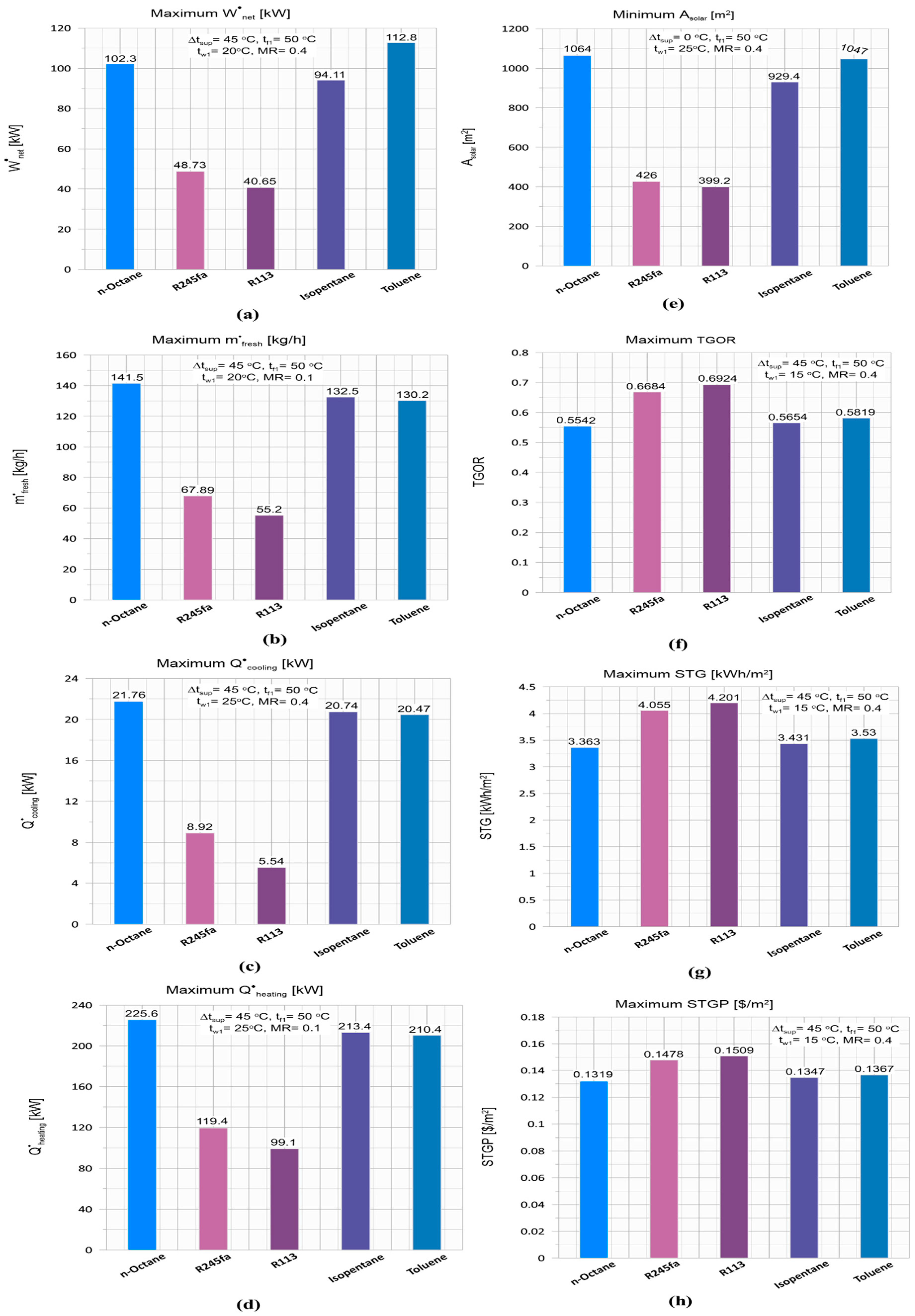
4.4. The Impact of Different ORC Fluids

The thermal performance of the proposed poly-generation systems is related to the type of working fluids. Therefore, the effect of organic working fluids on the system productivity and performance indicators is being studied and presented. Based on the results and analysis offered in the previous sections, the IS-I poly-generation system was selected for the application of the study of the impact of the working fluids as it has the highest performance indicators compared to the basic system and IS-II poly-generation. In the present work, five working fluids (n-octane, R245fa, R113, isopentane, and toluene) are selected to analyze the thermal performance of the proposed IS-I poly-generation system. The organic working fluid properties tested in the simulation considering ozone depletion potential (ODP), global warming potential (GWP), and suitable operation conditions are tabulated in Table 4. This section will present and discuss the effect of working fluids on the system’s productivity and performance indicators. At the same time, the impact of Δtsup, tf1, tw1, and MR on the system productivity and performance indicators were already presented and discussed in the previous sections.
A comprehensive parametric study was performed to examine the effects of working fluids on the proposed IS-I poly-generation system performance. For this purpose, a comparison of primary productivity and performance indicators, including electrical power generation, freshwater productivity ( m f r e s h ), space cooling capacity ( Q c o o l i n g ), domestic heating capacity ( Q h e a t i n g ), total gained output ratio (TGOR), specific total gained energy (STG), specific total earned energy equivalent cost (STGP), the thermal efficiency of ORC ( η O R C ), gain output ratio (GORHDH), coefficient of performance of DCS (COPDCS), and area of solar collectors (Asolar) for all the working fluids is presented in Figure 4 and Figure 5.
Figure 4a–d and Figure 5a–d show the effects of Δtsup on the system productivity and performance indicators of the proposed IS-I poly-generation system with different working fluids at tf1 = 50 °C, tw1 = 20 °C, and MR = 0.4. As shown in Figure 4a–d, the best-performing fluids are found to be those that show high performance for system productivity ( W n e t , m f r e s h , Q c o o l i n g and Q h e a t i n g ) specifically, n-octane, isopentane, and toluene. This is due to increased energy input and rejection in the evaporator and condenser of ORC, respectively. The mass flow rate of organic fluid is constant. Therefore, energy input and energy rejection are related to the enthalpy’s differences through the evaporator and condenser, which depend on the physical properties of the working fluids at the same evaporative and condenser temperatures. By contrast, working fluids, R113 and R245fa, have high performance for the system performance indicators (TGOR, STG, STGP, GORHDH, and COPDCS). This can be explained by comparing the decrease in the amount of energy input to the system, which was found to be less than the decrease in system productivity. Therefore, performance indicators have increased. Additionally, n-octane has the highest values of m f r e s h , Q c o o l i n g , Q h e a t i n g and Asolar, while toluene has the highest value of W n e t . At Δtsup = 30–45 °C, the m f r e s h , Q c o o l i n g and Q h e a t i n g for toluene and isopentane have almost the same values.
The maximum system productivity of W n e t , m f r e s h , Q c o o l i n g and Q h e a t i n g and solar collectors area (Asolar) for toluene and R113 at Δtsup = 45 °C are 99.74 and 35.68 kW, 107.2 and 51.41 kg/h, 19.65 and 3.717 kW, 139.1 and 76.84 kW, and 1202 and 478.6 m2, respectively. The maximum main system performance indicators of TGOR, STG, and STGP for toluene and R113 at Δtsup = 45 °C are 0.5423 and 0.6231, 3.29 and 3.781 kWh/m2, and 0.1318 and 0.1489 $/m2, respectively. The improvement in W n e t , m f r e s h , Q c o o l i n g and Q h e a t i n g , when using toluene instead of R113 at Δtsup = 45 °C, are 179.5%, 108.5%, 428.6%, and 81%, respectively.
Figure 4e–l and Figure 5e–l illustrate the effect of tf1 and tw1 on the productivity and performance indicators of the proposed IS-I poly-generation system with different working fluids at various operating indicators. The working fluids, n-octane, isopentane, and toluene, have the highest system productivity ( W n e t , m f r e s h , Q c o o l i n g and Q h e a t i n g ) and solar collector area (Asolar). Moreover, the fluids R113 and R245fa have high performance for the system performance indicators (TGOR, STG, STGP, GORHDH, and COPDCS). This is due to the same reasons that were explained and presented in the discussion of Figure 4a–d. As shown in Figure 4 and Figure 5, the maximum system productivity of W n e t , m f r e s h , Q c o o l i n g , and Q h e a t i n g and solar collectors area (Asolar) for toluene and R113 at tf1 = 40 °C are 112.8 and 40.65 kw, 107.9 and 52.43 kg/h, 19.81 and 4.049 kW, 139.8 and 78.09 kW, and 1237 and 497.3 m2, respectively. Furthermore, the maximum system performance indicators of TGOR, STG, and STGP for toluene and R113 at tf1 = 40 °C are 0.5499 and 0.6284, 3.336 and 3.812 kWh/m2, and 0.1348 and 0.1513 $/m2, respectively. Additionally, the improvements in W n e t , m f r e s h , Q c o o l i n g , and Q h e a t i n g using toluene instead of R113 at tf1 = 40 °C are 177.5%, 105.8%, 389.25%, and 79%, respectively.
Figure 4m–p and Figure 5m–p show the effects of MR on the system productivity and performance indicators of the proposed IS-I poly-generation system with different working fluids at Δtsup = 45 °C, tf1 = 50 °C, and tw1 = 20 °C. The working fluids, n-octane, isopentane, and toluene, have the highest system productivity ( W n e t , m f r e s h , Q c o o l i n g , and Q h e a t i n g ) and solar collector area (Asolar). This is because of the same reasons stated and provided in Figure 3 discussion. Additionally, as shown in Figure 5n–p, n-octane, isopentane, and toluene have the best performance for system performance indicators (TGOR, STG, STGP, GORHDH, and COPDCS) with MR 0.15 for n-octane and isopentane vs. R113 and R245fa, and MR 0.2 for toluene versus other working fluids. Moreover, the working fluids, R113 and R245fa, have high performance for the system performance indicators (TGOR, STG, STGP, GORHDH, and COPDCS) at MR ≥ 0.2 for R245fa and MR ≥ 0.25 for R113.
Figure 6 shows the maximum system productivity and performance indicators for different working fluids. The data displayed in Figure 6 were drawn based on the results presented in Figure 4 and Figure 5 to help researchers, solar poly-generation developers, power plant designers, and investors obtain the highest values of system productivity and performance indicators in a simplified and transparent form. Based on the data presented in Figure 6, researchers, solar poly-generation developers, power plant designers, and investors can choose the working fluid type according to the operating range values.

4.5. Comparisons with Other Reported Systems

According to the authors’ review, we compare our results with some integrated systems in the literature to prove the current proposed systems’ capability, reliability, applicability, and practical use. Co-generation and tri-generation systems for generating cooling, heating, power, and fresh water available in the literature are selected as they are comparable to the currently proposed systems. However, they differ in operating conditions from our chosen conditions, as shown in Table 5. The maximum TGOR and maximum freshwater productivity are chosen as performance and productivity indicators for comparison.
As shown in Table 5, the maximum TGOR of the current system (IS-I) does not differ significantly from those of the comparable systems. It is higher than that presented by [41,43,45] and closer to [40,47], while it is lower than [25,42,44,46,48,49,52]. Moreover, the maximum water productivity of the current system (IS-II) is higher than [11,12,50,53] and lower than [25,36,51]. The discrepancies are due to the differences in operating conditions, type, configuration, and prime mover of the comparable systems.

5. Conclusions and Recommendations

Theoretical investigations of three different and novel solar-driven poly-generation systems (BS, IS-I, IS-II) integrated with ORC, HDH, and DCS with other heat recovery systems have been carried out for producing electricity, space cooling/domestic heating, and freshwater production for small- and medium-scale buildings. The influence of different operating and design parameters on the systems’ productivity and performance indicators parameters were investigated. In addition, the impacts of various organic working fluid types (n-octane, R245fa, R113, isopentane, and toluene) on the best system performance were also carried out. The IS-I is selected to study the effects of organic working fluid on the systems’ productivity and performance indicators parameters where the obtained results show that it has higher system performance. The main concluding remarks that can be considered as design guidelines are listed briefly in the following points:
  • COPDCS, TGOR, STG, and STGP improve with an increase in MR until they reach peak values, and then they decrease considerably.
  • System IS-I has higher GORHDH, TGOR, STG, and STGP than the other systems (BS and IS-II systems), while the IS-II system has higher values than the BS system. In comparison, the IS-II system has better COPDCS than the IS-I and BS systems.
  • The average enhancement percentage of TGOR using integrated poly-generation systems over the separated ones is 68.5%, 68.5%, and 95.5% for BS, IS-I, and IS-II systems, respectively, within the studied ranges of Δtsup, tf1, tw1, and MR.
  • IS-I has a maximum TGORimp of 197.4% at Δtsup = 45 °C, tf1 = 50 °C, tw1 = 20 °C, and MR = 0.1.
  • The maximum main system performance indicators of TGOR, STG, and STGP for toluene and R113 at Δtsup = 45 °C are 0.5423 and 0.6231, 3.29 and 3.781 kWh/m2, and 0.1318 and 0.1489 $/m2, respectively.
  • n-Octane, isopentane, and toluene have the highest performance for system performance indicators at MR ≤ 0.15 for n-octane and isopentane compared to R113 and R245fa and MR ≤ 0.2 for toluene compared to all working fluids.
  • The working fluids, R113 and R245fa, have high performance for the system performance indicators at MR ≥ 0.2 for R245fa and MR ≥ 0.25 for R113.
  • The maximum system productivity of W n e t , m f r e s h , Q c o o l i n g , and Q h e a t i n g and solar collectors’ area (Asolar) for toluene and R113 at tf1= 40 °C are 112.8 and 40.65 kw, 107.9 and 52.43 kg/h, 19.81 and 4.049 kW, 139.8 and 78.09 kW, and 1237 and 497.3 m2, respectively.
  • The improvements in W n e t , m f r e s h , Q c o o l i n g , and Q h e a t i n g with using toluene instead of R113 at tf1 = 40 °C are 177.5%, 105.8%, 389.25%, and 79%, respectively.
  • n-Octane, isopentane, and toluene have higher systems productivity ( W n e t , m f r e s h , Q c o o l i n g , and Q h e a t i n g ) and higher solar collector area (Asolar). However, R113 and R245fa have higher performance for the system performance indicators (TGOR, STG, STGP, GORHDH, and COPDCS).
  • Finally, using different improvements of ORC, types of A/C (adsorption and absorption) and desalination (RO, MED) systems in addition to monthly transient analysis along the year are recommended as future work for poly-generation systems.

Author Contributions

Conceptualization, F.A.A., H.F.E., A.F., S.A., M.A.A. and H.A.R.; Data curation, H.F.E.; Formal analysis, H.F.E., A.F. and H.A.R.; Funding acquisition, F.A.A.; Investigation, H.F.E.; Methodology, H.F.E. and A.F.; Project administration, F.A.A.; Software, A.F., J.M. and S.A.; Supervision, S.A. and M.A.A.; Validation, H.F.E. and A.F.; Visualization, H.A.R.; Writing—original draft, H.F.E., A.F. and H.A.R.; Writing—review and editing, J.M., F.A.A., S.A., M.A.A. and H.A.R. All authors have read and agreed to the published version of the manuscript.

Funding

This research was funded by Researchers Supporting Project number (RSP2022R515), King Saud University, Riyadh, Saudi Arabia.

Institutional Review Board Statement

Not Applicable.

Informed Consent Statement

Not Applicable.

Data Availability Statement

Not Applicable.

Acknowledgments

The authors extend their appreciation to the Researchers Supporting Project number (RSP2022R515), King Saud University, Riyadh, Saudi Arabia for funding this research work.

Conflicts of Interest

The authors declare no conflict of interest.

Nomenclature

AArea, m2
CpSpecific heat, kJ/kg K
F1, F2Combined potential, --
hfgWater latent heat of evaporation, kJ/kg
hSpecific enthalpy, kJ/kg
ITTotal solar intensity, W/m2
mMass flow rate, kg/s
QHeat transfer rate, kW
tTemperature, °C
WHumidity ratio, gv/kga
WPower, kW
Greek symbols
ηEfficiency
ηF1, ηF2Efficiency of the desiccant wheel
εEffectiveness
ΔτTime, hours
Subscript
aAir/dry air/actual
atmAtmosphere
avgAverage
BSBasic system
condCondenser
EvapEvaporator
gGenerator
humHumidifier
HEHeat exchanger
i = 1,2,3Index referring to various positions of the desiccant system
impImprovement
inInput
indIndependent
maMoist air
vWater vapour
regRegeneration
R,aReturn air
P,aProcess air
PPump
tTurbine
wSeawater
1, 2, 3, ……State points
Abbreviations
BSBasic system
COPCoefficient of performance
DCSDesiccant cooling system
GORGain output ratio
HDHHumidification dehumidification
ICEInternal combustion engine
IS-IImproved system-I
IS-IIImproved system-II
KSAKingdom of Saudi Arabia
LBSElithium bromide–water simple effect
MRMass flow rate ratio
MEDMulti effect desalination
ORCOrganic Rankine cycle
ROReverse osmosis
SOFC Solid oxide fuel cell
STGSpecific total gained energy, kWh/m2
STGPSpecific total gained energy equivalent price, $/m2
TGORTotal gained output ratio

References

  1. Mehrpooya, M.; Sharifzadeh, M.M.M.; Rosen, M.A. Energy and exergy analyses of a novel power cycle using the cold of LNG (liquefied natural gas) and low-temperature solar energy. Energy 2016, 95, 324–345. [Google Scholar] [CrossRef]
  2. Karellas, S.; Braimakis, K. Energy–exergy analysis and economic investigation of a cogeneration and trigeneration ORC–VCC hybrid system utilizing biomass fuel and solar power. Energy Convers. Manag. 2016, 107, 103–113. [Google Scholar] [CrossRef]
  3. Sahoo, U.; Kumar, R.; Pant, P.C.; Chaudhury, R. Scope and sustainability of hybrid solarebiomass power plant with cooling, desalination in polygeneration process in India. Renew. Sustain. Energy Rev. 2015, 51, 304–316. [Google Scholar] [CrossRef]
  4. Khaliq, A.; Refaey, H.; Alharthi, M.A. Development and analysis of a novel CSP source driven cogeneration cycle for the production of electric power and low temperature refrigeration. Int. J. Refrig. 2021, 130, 330–346. [Google Scholar] [CrossRef]
  5. Meng, N.; Li, T.; Gao, X.; Liu, Q.; Li, X.; Gao, H. Thermodynamic and techno-economic performance comparison of two-stage series organic Rankine cycle and organic Rankine flash cycle for geothermal power generation from hot dry rock. Appl. Therm. Eng. 2022, 200, 117715. [Google Scholar] [CrossRef]
  6. Al-Sayyab, A.K.S.; Mota-Babiloni, A.; Barragán-Cervera, Á.; Navarro-Esbrí, J. Dual fluid trigeneration combined organic Rankine-compound ejector-multi evaporator vapour compression system. Energy Convers. Manag. 2022, 267, 115876. [Google Scholar] [CrossRef]
  7. Habka, M.; Ajib, S. Evaluation of mixtures performances in Organic Rankine Cycle when utilizing the geothermal water with and without cogeneration. Appl. Energy 2015, 154, 567–576. [Google Scholar] [CrossRef]
  8. Kumar, R.; Shukla, A.K.; Sharma, M.; Nandan, G. Thermodynamic investigation of water generating system through HDH desalination and RO powered by organic Rankine cycle. Mater. Today 2021, 46, 5256–5261. [Google Scholar] [CrossRef]
  9. Yari, M.; Ariyanfar, L.; Aghdam, E.A. Analysis and performance assessment of a novel ORC based multigeneration system for power, distilled water and heat. Renew. Energy 2018, 119, 262–281. [Google Scholar] [CrossRef]
  10. He, W.; Han, D.; Xu, L.; Yue, C.; Pu, W. Performance investigation of a novel water–power cogeneration plant (WPCP) based on humidification dehumidification (HDH) method. Energy Convers. Manag. 2016, 110, 184–191. [Google Scholar] [CrossRef]
  11. Nada, S.; Fouda, A.; Mahmoud, M.; Elattar, H. Experimental investigation of air-conditioning and HDH desalination hybrid system using new packing pad humidifier and strips-finned helical coil. Appl. Therm. Eng. 2021, 185, 116433. [Google Scholar] [CrossRef]
  12. Fouda, A.; Nada, S.; Elattar, H. An integrated A/C and HDH water desalination system assisted by solar energy: Transient analysis and economical study. Appl. Therm. Eng. 2016, 108, 1320–1335. [Google Scholar] [CrossRef]
  13. Elattar, H.F.; Nada, S.A.; Al-Zahrani, A.; Fouda, A. Humidification-dehumidification water desalination system integrated with multiple evaporators/condensers heat pump unit. Int. J. Energy Res. 2020, 44, 6396–6416. [Google Scholar] [CrossRef]
  14. Liu, H.; Zhou, Q.; Zhao, H.; Wang, P. Experiments and thermal modeling on hybrid energy supply system of gas engine heat pumps and organic Rankine cycle. Energy Build. 2015, 87, 226–232. [Google Scholar] [CrossRef]
  15. Sibilio, S.; Rosato, A.; Ciampi, G.; Scorpio, M.; Akisawa, A. Building-integrated trigeneration system: Energy, environmental and economic dynamic performance assessment for Italian residential applications. Renew. Sustain. Energy Rev. 2017, 68, 920–933. [Google Scholar] [CrossRef]
  16. Jradi, M.; Riffat, S. Tri-generation systems: Energy policies, prime movers, cooling technologies, configurations and operation strategies. Renew. Sustain. Energy Rev. 2014, 32, 396–415. [Google Scholar] [CrossRef]
  17. Leonzio, G. An innovative trigeneration system using biogas as renewable energy. Chin. J. Chem. Eng. 2018, 26, 1179–1191. [Google Scholar] [CrossRef]
  18. Zhang, X.; Li, H.; Liu, L.; Zeng, R.; Zhang, G. Analysis of a feasible trigeneration system taking solar energy and biomass as co-feeds. Energy Convers. Manag. 2016, 122, 74–84. [Google Scholar] [CrossRef]
  19. Maraver, D.; Uche, J.; Royo, J. Assessment of high temperature organic Rankine cycle engine for polygeneration with MED desalination: A preliminary approach. Energy Convers. Manag. 2012, 53, 108–117. [Google Scholar] [CrossRef]
  20. Tzivanidis, C.; Bellos, E. A comparative study of solar-driven trigeneration systems for the building sector. Energies 2020, 13, 2074. [Google Scholar] [CrossRef]
  21. Calise, F.; d’Accadia, M.D.; Macaluso, A.; Piacentino, A.; Vanoli, L. Exergetic and exergoeconomic analysis of a novel hybrid solar–geothermal polygeneration system producing energy and water. Energy Convers. Manag. 2016, 115, 200–220. [Google Scholar] [CrossRef]
  22. Zare, V. A comparative thermodynamic analysis of two tri-generation systems utilizing low-grade geothermal energy. Energy Convers. Manag. 2016, 118, 264–274. [Google Scholar] [CrossRef]
  23. Rostamzadeh, H.; Ebadollahi, M.; Ghaebi, H.; Shokri, A. Comparative study of two novel micro-CCHP systems based on organic Rankine cycle and Kalina cycle. Energy Convers. Manag. 2019, 183, 210–229. [Google Scholar] [CrossRef]
  24. Pang, K.-C.; Chen, S.-C.; Hung, T.-C.; Feng, Y.-Q.; Yang, S.-C.; Wong, K.-W.; Lin, J.-R. Experimental study on organic Rankine cycle utilizing R245fa, R123 and their mixtures to investigate the maximum power generation from low-grade heat. Energy 2017, 133, 636–651. [Google Scholar] [CrossRef]
  25. Gholizadeh, T.; Vajdi, M.; Rostamzadeh, H. Exergoeconomic optimization of a new trigeneration system driven by biogas for power, cooling, and freshwater production. Energy Convers. Manag. 2020, 205, 112417. [Google Scholar] [CrossRef]
  26. Ghorab, M.; Yang, L.; Entchev, E.; Lee, E.-J.; Kang, E.-C.; Kim, Y.-J.; Bae, S.; Nam, Y.; Kim, K. Multi-objective optimization of hybrid renewable Tri-generation system performance for buildings. Appl. Sci. 2022, 12, 888. [Google Scholar] [CrossRef]
  27. Li, J.; Zoghi, M.; Zhao, L. Thermo-economic assessment and optimization of a geothermal-driven tri-generation system for power, cooling, and hydrogen production. Energy 2022, 244, 123151. [Google Scholar] [CrossRef]
  28. Fouda, A.; Nada, S.; Elattar, H.; Rubaiee, S.; Al-Zahrani, A. Performance analysis of proposed solar HDH water desalination systems for hot and humid climate cities. Appl. Therm. Eng. 2018, 144, 81–95. [Google Scholar] [CrossRef]
  29. Dincer, I.; Demir, M.E. Steam and Organic Rankine Cycles. Compr. Energy Syst. 2018, 4, 264–311. [Google Scholar]
  30. Eldean, M.A.S.; Soliman, A.M. Study of using solar thermal power for the margarine melting heat process. J. Sol. Energy Eng. 2015, 137, 0210041–2100413. [Google Scholar]
  31. Walraven, D.; Laenen, B.; D’Haeseleer, W. Comparison of thermodynamic cycles for power production from low-temperature geothermal heat sources. Energy Convers. Manag. 2013, 66, 220–233. [Google Scholar] [CrossRef] [Green Version]
  32. Islam, S.; Dincer, I.; Yilbas, B.S. Development, analysis and assessment of solar energy based multi-generation system with thermoelectric generator. Energy Convers. Manag. 2018, 156, 746–756. [Google Scholar] [CrossRef]
  33. Azhar, M.S.; Rizvi, G.; Dincer, I. Integration of renewable energy based multigeneration system with desalination. Desalination 2017, 404, 72–78. [Google Scholar] [CrossRef]
  34. Wang, N.; Wang, D.; Dong, J.; Wang, H.; Wang, R.; Shao, L.; Zhu, Y. Performance assessment of PCM-based solar energy assisted desiccant air conditioning system combined with a humidification-dehumidification desalination unit. Desalination 2020, 496, 114705. [Google Scholar] [CrossRef]
  35. Panaras, G.; Mathioulakis, E.; Belessiotis, V.; Kyriakis, N. Theoretical and experimental investigation of the performance of a desiccant air-conditioning system. Renew. Energy 2010, 35, 1368–1375. [Google Scholar] [CrossRef]
  36. Nada, S.; Elattar, H.; Fouda, A. Performance analysis of proposed hybrid air conditioning and humidification–dehumidification systems for energy saving and water production in hot and dry climatic regions. Energy Convers. Manag. 2015, 96, 208–227. [Google Scholar] [CrossRef]
  37. Zubair, S.M.; Antar, M.A.; Elmutasim, S.; Lawal, D.U. Performance evaluation of humidification-dehumidification (HDH) desalination systems with and without heat recovery options: An experimental and theoretical investigation. Desalination 2018, 436, 161–175. [Google Scholar] [CrossRef]
  38. Galloni, E.; Fontana, G.; Staccone, S. Design and experimental analysis of a mini ORC (organic Rankine cycle) power plant based on R245fa working fluid. Energy 2015, 90, 768–775. [Google Scholar] [CrossRef]
  39. Mohammadi, S.H.; Ameri, M. Energy and exergy analysis of a tri-generation water-cooled air conditioning system. Energy Build. 2013, 67, 453–462. [Google Scholar] [CrossRef]
  40. Lian, Z.; Chua, K.; Chou, S. A thermoeconomic analysis of biomass energy for trigeneration. Appl. Energy 2010, 87, 84–95. [Google Scholar] [CrossRef]
  41. Tehrani, S.S.M.; Saffar-Avval, M.; Mansoori, Z.; Kalhori, S.B.; Abbassi, A.; Dabir, B.; Sharif, M. Development of a CHP/DH system for the new town of Parand: An opportunity to mitigate global warming in Middle East. Appl. Therm. Eng. 2013, 59, 298–308. [Google Scholar] [CrossRef]
  42. Ahmadi, P.; Dincer, I.; Rosen, M.A. Exergo-environmental analysis of an integrated organic Rankine cycle for trigeneration. Energy Convers. Manag. 2012, 64, 447–453. [Google Scholar] [CrossRef]
  43. Choi, J.H.; Ahn, J.H.; Kim, T.S. Performance of a triple power generation cycle combining gas/steam turbine combined cycle and solid oxide fuel cell and the influence of carbon capture. Appl. Therm. Eng. 2014, 71, 301–309. [Google Scholar] [CrossRef]
  44. do Espirito Santo, D.B. An energy and exergy analysis of a high-efficiency engine trigeneration system for a hospital: A case study methodology based on annual energy demand profiles. Energy Build. 2014, 76, 185–198. [Google Scholar] [CrossRef]
  45. Puig-Arnavat, M.; Bruno, J.C.; Coronas, A. Modeling of trigeneration configurations based on biomass gasification and comparison of performance. Appl. Energy 2014, 114, 845–856. [Google Scholar] [CrossRef]
  46. Al-Sulaiman, F.A.; Dincer, I.; Hamdullahpur, F. Energy analysis of a trigeneration plant based on solid oxide fuel cell and organic Rankine cycle. Int. J. Hydrogen Energy 2010, 35, 5104–5113. [Google Scholar] [CrossRef]
  47. Huang, Y.; Wang, Y.; Rezvani, S.; McIlveen-Wright, D.; Anderson, M.; Mondol, J.; Zacharopolous, A.; Hewitt, N. A techno-economic assessment of biomass fuelled trigeneration system integrated with organic Rankine cycle. Appl. Therm. Eng. 2013, 53, 325–331. [Google Scholar] [CrossRef]
  48. Fong, K.; Lee, C. Investigation on zero grid-electricity design strategies of solid oxide fuel cell trigeneration system for high-rise building in hot and humid climate. Appl. Energy 2014, 114, 426–433. [Google Scholar] [CrossRef]
  49. Chen, Y.; Zhao, D.; Xu, J.; Wang, J.; Lund, P.D. Performance analysis and exergo-economic optimization of a solar-driven adjustable tri-generation system. Energy Convers. Manag. 2021, 233, 113873. [Google Scholar] [CrossRef]
  50. Nada, S.; Elattar, H.; Fouda, A. Experimental study for hybrid humidification–dehumidification water desalination and air conditioning system. Desalination 2015, 363, 112–125. [Google Scholar] [CrossRef]
  51. Elattar, H.; Fouda, A.; Nada, S. Performance investigation of a novel solar hybrid air conditioning and humidification–dehumidification water desalination system. Desalination 2016, 382, 28–42. [Google Scholar] [CrossRef]
  52. Bellos, E.; Tzivanidis, C. Multi-objective optimization of a solar driven trigeneration system. Energy 2018, 149, 47–62. [Google Scholar] [CrossRef]
  53. Abdelhay, A.; Fath, H.S.; Nada, S.A. Solar driven polygeneration system for power, desalination and cooling. Energy 2020, 198, 117341. [Google Scholar] [CrossRef]
Figure 1. Schematic diagram of proposed multigeneration systems: (a) The basic system (BS), (b) the improved system-I (IS-I), and (c) the improved system-II (IS-II).
Energies 15 08286 g001
Figure 2. Comparisons of proposed systems with independent individual systems on TGOR & TGORind for different operating parameters: (a) Δtsup; (b) tf1; (c) tw1; (d) MR.
Energies 15 08286 g002
Figure 3. The impact of studied parameters on proposed total output improvements (systems evaluation): (a) Δtsup; (b) tf1; (c) tw1; (d) MR.
Energies 15 08286 g003
Figure 4. Variations of the systems’ productivity with various studied parameters: (ad) Δtsup; (eh) tf1; (il) tw1; (mp) MR.
Energies 15 08286 g004
Figure 5. Variations of the systems’ performance indicators with various studied parameters: (ad) Δtsup; (eh) tf1; (il) tw1; (mp) MR.
Energies 15 08286 g005
Figure 6. Comparisons of maximum proposed systems’ productivity and performance indicators for different ORC fluids: (a) W n e t ; (b) m f r e s h ; (c) Q c o o l i n g ; (d) Q h e a t i n g ; (e) Asolar; (f) TGOR; (g) STG; (h) STGP.
Energies 15 08286 g006
Table 1. Studied operating parameters, values, and ranges.
ParameterValue/Range
Superheat degree at turbine inlet, Δtsup0–45 °C
ORC evaporation temperature, tevap150 °C
ORC condensation temperature, tf140–60 °C
ORC fluid mass flow rate, mORC1 kg/s
Mass flow rate ratio, MR0.1–0.4
Ambient air inlet temperature, ta135 °C
Ambient air inlet humidity, wa115 gv/kga
Seawater inlet temperature, tw115–25 °C
Conditioned space air temperature, ta525 °C
Conditioned space air humidity, wa512 gv/kga
Average solar intensity, Iavg0.8 kW/m2 (Jeddah city)
Table 2. Efficiencies of the system’s components.
ParameterValue
Dehumidifier efficiency, ηDh [8].0.95
Efficiency of the desiccant wheel, ηF1 [19,21]0.05
Efficiency of the desiccant wheel, ηF2 [19,27]0.95
Efficiency of evaporative cooler-1, ηDEC-1 [19,27]0.9
Efficiency of evaporative cooler-2, ηDEC-2 [19,27]0.9
Efficiency of heat exchangers, ηHE-1, ηHE-2, ηHE-3, ηHE-4 [19,27]0.8
Efficiency of the evacuated tube solar collector, ηsolar [32]0.632
Efficiency of the electrical generator of ORC, ηg [33]0.95
ORC pump efficiency, ηpump [33]0.85
ORC turbine efficiency, ηturbine [33]0.85
Table 3. Validation of the current model with the published data for HDH, ORC, and DCS systems.
HDHORCDCS
mw/ma
(kgw/kga)
GORHDHPevap
[bar]
ηORCTreg
[°C]
COPDCS
Exp.
Zubair et al. [37]
Num. Current ModelRelative Error
[%]
Exp.
Galloni et al. [38]
Num. Current ModelRelative Error
[%]
Exp. Panaras et al. [35]Num. Current ModelRelative Error
[%]
1.360.3350.32536.1806.3135.8427.46500.3870.4023.8
6.8976.3476.350.05
1.890.3650.3752.77.9065.2416.9632600.4120.4314.6
8.8068.1507.4239
2.270.3750.3873.29.5878.9817.77713.4700.4430.4706.1
9.9558.8897.93110.8
Table 4. Properties of the selected working fluids.
Working FluidNormal
Boiling
Point (°C) at 1 Bar
Critical
Temperature
(°C)
Critical
Pressure
(MPa)
ODPGWP
n-Octane125.68296.22.4970Low
R245fa151543.701050
R113482143.40.804800
Isopentane27.78187.23.3700<10
Toluene111.7318.84.1230 3.30 3.3
Table 5. Comparison of the current systems with other reported systems.
Refs.System TypeSystem ProductivitiesPrime MoverApplicationStudy DescriptionMax. Fresh Water Productivity
(kg/h)
TGORmaxmax
Lian et al. [40]tri-generationCooling/Heating/PowerSteam turbine (Biomass)IndustrialModeling---72.8%
Tehrani et al. [41]co-generation Heating/PowerGas turbineIndustrialModeling---59.96%
Ahmadi et al. [42]tri-generationCooling/Heating/PowerGas turbineResidentialModeling---89%
Nada et al. [36]co-generationCooling/Fresh watervapor compression refrigeration cycleResidentialModeling375---
Choi et al. [43]tri-generation Cooling/Heating/Powercombined cycle gas turbineCommercialModeling---53.3%
Santo [44]tri-generation Cooling/Heating/PowerInternal combustion engineMedicalModeling---77%
Fouda et al. [12]co-generationCooling/Fresh watervapor compression refrigeration cycleResidentialModeling21.5 ---
Puig-Arnavat et al. [45]tri-generation Cooling/Heating/PowerInternal combustion engineCommercialModeling---64.2%
Al-Sulaiman et al. [46]tri-generation Cooling/Heating/PowerSOFC/ORC combinedCommercialModeling---74%
Huang et al. [47]tri-generation Cooling/Heating/PowerORC CommercialModeling---71.7%
Fong, C.K. Lee [48]tri-generation Cooling/Heating/PowerFuel cellResidentialModeling---76.7%
Nada et al. [11]co-generationCooling/Fresh watervapor compression refrigeration cycleResidentialExperimental17.42---
Chen et al. [49]tri-generation Cooling/Heating/PowerSolar/ORC combinedResidentialModeling---82.96%
Nada et al. [50]co-generation Cooling/Fresh watervapor compression refrigeration cycleResidentialExperimental9.05---
Elattar et al. [51]co-generationCooling/Fresh watervapor compression refrigeration cycleResidentialModeling534 ---
Bellos and Tzivanidis [52]tri-generation Cooling/Heating/PowerSolarResidentialModeling---87.39%
Gholizadeh et al. [25]tri-generation Power/Cooling/Fresh waterGeothermalIndustrialModeling5400 92.75%
Abdelhay et al. [53]tri-generation electricity, cooling, and potable waterSolar/Rankine cycleResidentialModeling22.9---
Current systems MultigenerationCooling/Heating/Power/Fresh waterSolar/ORC combinedResidentialModeling214.7 (IS-II)69.24% (IS-I)
Publisher’s Note: MDPI stays neutral with regard to jurisdictional claims in published maps and institutional affiliations.

