
Comparative Study of AVR Control Systems Considering a Novel Optimized PID-Based Model Reference Fractional Adaptive Controller


1
Engineering Physics and Mathematics Department, Faculty of Engineering, Ain Shams University, Cairo 11517, Egypt
2
Electrical Power and Machines Department, Faculty of Engineering, Ain Shams University, Cairo 11517, Egypt
*
Author to whom correspondence should be addressed.
Energies 2023, 16(2), 830; https://doi.org/10.3390/en16020830
Submission received: 13 December 2022
/
Revised: 2 January 2023
/
Accepted: 9 January 2023
/
Published: 11 January 2023
(This article belongs to the Special Issue Renewable Energy Management System and Power Electronic Converters)
Abstract
:Voltage regulation is a crucial task for electrical grids in the presence of high penetration levels of renewable energies. The regulation of generator excitation improves the stability of the power system. An essential tool for controlling the excitation of generators is the automatic voltage regulator (AVR). It is advised to use a controller to increase the reliability of an AVR. A survey about different types of controllers is proposed in this paper. Then, a novel optimized PID-Based model reference fractional adaptive controller is proposed, with detailed mathematical modeling. The novel controller was compared to the controllers in the survey. The novel proposed controller proved its superiority over the other controllers through its fast response and low rising and settling times. Moreover, the proposed controller smoothly and instantaneously tracked dynamic reference changes.
1. Introduction
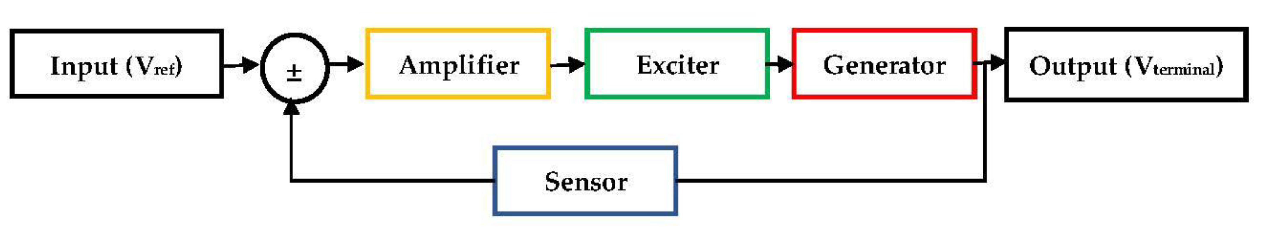
Voltage variation is one of the most serious issues for electrical grids, especially when renewable energies are heavily used. Under various generating or loading situations, an automatic voltage regulator (AVR) regulates the output voltage within its nominal value. To achieve this, it regulates the value of the exciter current [1]. The amplifier, exciter, generator, and sensor are the major parts of a simple AVR system with linearized mathematical models [2]. The output voltage of this model is the terminal voltage of the generator, which exhibits instability and delayed reaction because of high field winding inductance and load changes. Figure 1 shows the AVR system components, starting with the input reference voltage signal and ending with the output terminal voltage signal. Each system component has its own predefined time constant. For an AVR system with amplifier, exciter, generator, and sensor time constants, respectively, the mathematical modeling equation in the Laplace domain for the overall system, without considering any controller, can be given by [3]:
where is the amplifier gain and , , , and are the time constants of the amplifier, exciter, generator, and sensor, respectively. Using the inverse Laplace transform, the system-governing differential equation in the time domain can be obtained as follows:
From the previous equation, the AVR dynamic system, without a controller, can be fully described by a fourth-order linear ordinary differential equation, and the dynamic system stability can be studied using the following characteristic equation:
The system stability is maintained for specified time constant values for the negative real part of the roots of the characteristic equation.
The performance parameters that should be studied alongside system stability are the maximum overshoot and the rise and settling times as well as the steady-state error. To improve previous performance indicators, a controller is utilized in the AVR system. The proportional-integral-derivative (PID) [2], fractional-order-proportional-integral-derivative (FOPID) [3], fuzzy adaptive (FA) [4,5], proportional-integral-derivative-accelerator (PIDA) [6], and fuzzy-adaptive-proportional-integral-derivative (FAPID) [7] controllers have been used by different researchers to satisfy adequate performance indicators.
As each controller has its own set of design parameters that consider many factors of the system, such as the order, time delays, nonlinear loads, changeable operating points, and others, optimization techniques are utilized to fine-tune these controllers under different objective functions such as the integral of square error (ISE), the integral of absolute error (IAE), and the integral of time-weighted square error (ITSE).
In this paper, a brief survey of different AVR controllers is presented. Moreover, a new controller based on basic model reference adaptive control (MRA) is proposed to achieve a novel instant response AVR system under dynamic reference voltages. The proposed controller was examined and compared with several other types that were introduced in the literature to prove its superiority.
This article is prepared as follows: Section 2 presents a detailed review of different types of controllers used to enhance the AVR system’s performance, with detailed mathematical modeling equations as well as optimization algorithms used with each one. Section 3 introduces the required mathematical preliminaries of the proposed new adaptive controller and the mathematical model of the AVR system using such a controller. In Section 4, the dynamic response of the proposed controller for the AVR system, compared to other techniques with specified optimized design parameters, is studied and analyzed under different reference signals with the same objective function. The paper is concluded in Section 5.
2. Literature Review
This survey illustrates various types of control systems used for AVR systems, along with their mathematical models, to demonstrate their improved terminal voltage responses. Several studies on each type are also conducted and compared with those of other controllers, with a focus on four different controller types (PID, PIDA, FOPID, and FAPID) that are adaptively tuned using various optimization techniques.
2.1. PID-Based AVR Dynamic System Model
The proportional-integral-derivative (PID) controller is the most commonly used controller in AVR circuits, and it mainly consists of three main components: constant gain (), constant integrator gain , and constant differentiator gain . This controller Laplace domain model is completely described in [8,9,10,11].
where and are the controller input and output, respectively. The controller time-domain dynamic equation is defined by:
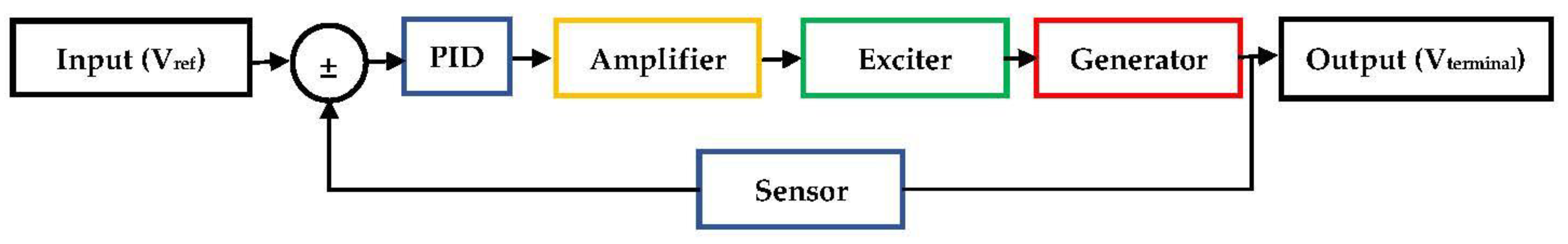
Using the PID controller, as connected in Figure 2, results in extracting the AVR system model in Equation (1) to consider the controller effect, which is fully described by:
The AVR dynamic system-governing differential equation in the time domain takes the form:
During the system design process, the PID-AVR system stability can be studied using the following system characteristic equation:
The main concern when designing a PID controller for the AVR system with predefined time constants is how to select the controller gains to keep the system stability under the optimal tracking of the input reference voltage. An AVR system that employs a genetic algorithm (GA) [8,9] to tune the PID controller was presented in [10,11]. It was concluded that the system has superior stability and response. In [12], the authors demonstrated that the use of tabu search (TS) [13,14,15] for adjusting the parameters of a PID-based AVR system outperformed Ziegler and Nichols’ technique (ZN). The multipath adaptive tabu search (MATS) is utilized to fine-tune the PID controller used for the AVR system [16,17]. It was concluded from the results that the MATS performs better than adaptive tabu search (ATS) [18] and classical tabu search (TS) utilizing a PID controller. According to [19], the AVR based on PID tuned by the intensified current search (ICS) provides superior efficiency and performance compared to the default current search (CS). The authors of [20] suggested the BAT algorithm [21,22,23,24] to tune the parameters of a PID-based AVR system. The provided results showed that the BAT method outperformed the PSO and ZN techniques [20].
The authors of [25] proposed using particle swarm optimization (PSO) [26,27] for tuning the PID-based AVR system. The authors also compared the results with PID being tuned with a GA to demonstrate the improved performance and response when PSO was used compared to a GA [25]. The superiority of reinforcement learning automata (RLA) [compared to the PSO and GA techniques was proven for adapting the AVR system [28,29,30]. Moreover, the modified RLA-based PID tuning parameters were superior to the PSO and ZN techniques [31]. However, the Taguchi combined genetic algorithm (TCGA) [32] used to tune the AVR-PID gains surpassed the PSO and GA techniques [33]. The authors of [34] proposed anarchic society optimization (ASO) [35] to tune the AVR-PID gains, which showed a more efficient response than velocity-relaxed PSO (VRPSO) and craziness-based PSO (CRPSO) [34]. Artificial bee colony (ABC) ] was utilized to tune AVR-based PID parameters, which offered superior performance compared to PSO [36,37,38,39] and the evolution algorithm (DE).
The gravitational search (GSA) [40] surpassed the default GSA and PSO in improving AVR system performance to tune the system PID controller [41]. In addition, the superiority of the GSA compared to the ABC, PSO, and DE algorithms for tuning PID-based AVR was demonstrated in [42]. The authors of [43] used the many optimizing liaisons (MOL) method to tune PID [44], which outperformed ABC, PSO, and DE for improving the performance of the AVR system. The adaptive particle swarm optimization (APSO) [45] outperformed the MOL and PSO algorithms for tuning PID-based AVR controller parameters [46]. The authors of [47] presented the local unimodal sampling (LUS) algorithm [48] and showed its superior performance over the ABC algorithm for tuning PID-based AVR. In [47], four objective functions, IAE, ISE, ITEA, and ITSE, were compared, and the results showed the outperformance of the ISE in terms of reduced overshoot and rise times.
The authors of [49] presented the harmony search algorithm (HSA) [50,51,52] for PID tuning and compared the results with the PSO technique. The results revealed the improved performance of the has-based AVR system compared to the PSO technique. The WCA was used to tune the PID-based AVR parameters and was proven to be superior to the ABC [53]. The authors of [54] presented the HCO to tune PID, and the results showed the enhanced performance of the AVR system in terms of diminished oscillations and the rising time compared to several optimization techniques. The teaching–learning-based optimization (TLBO) [55] was proposed to tune PID parameters using the ITAE objective function [56]. The AVR system was kept robust against changes on the order of ±50% in the time constants. The authors of [57] showed the superior performance of the TLBO algorithm in tuning PID-based AVR compared to the LUS, MOL, ABC, GA, and DE techniques. The AVR system based on the TLBO withstood changes in generator gains and time constants.
A hybrid technique based on the GA and the PSO algorithms [58] was proposed to tune the PID-based AVR parameters, where the performance was improved over using only the GA or the PSO [59]. The authors of [60] presented a hybrid GA and bacterial foraging (BF) algorithm [61,62] and proved its superiority in comparison to the hybrid PSO and GA technique. The outperformance of the hybrid PSO-GSA was demonstrated against the ZN, PSO, and MOL techniques used for tuning the PID-based AVR with the ITAE objective [63,64].
2.2. PIDA-Based AVR Dynamic System Model
The PIDA controller is one of most recent controllers studied by many researchers, especially for AVR system control. The generalized transfer function of an n-order-type PIDA controller can be written as:
where are the controller design parameters.
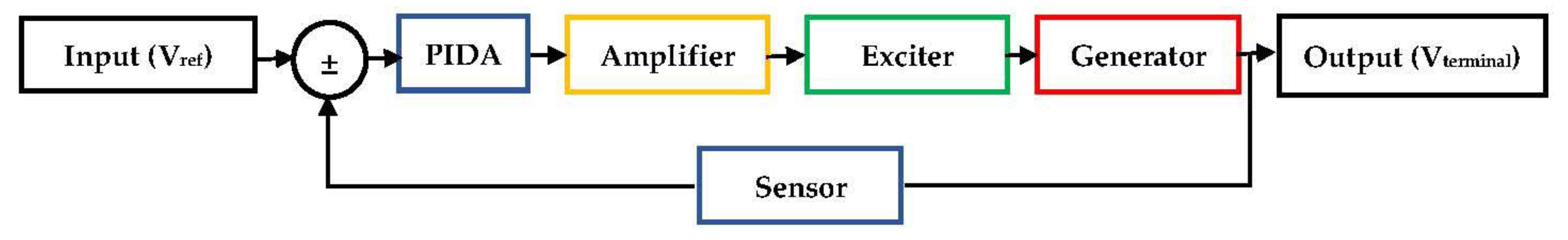
Selecting the controllers’ parameters for an optimal control system is the main concern of many studies where different types of metaheuristic optimization techniques are employed. The AVR system modeling equation under this controller, which is connected as in Figure 3, in the Laplace domain is defined as:
To investigate how the system complexity increased when this controller was used, we can first obtain the system-governing differential equation of the second-order PIDA type with n = 2. After taking the inverse Laplace transform to Equation (10), with n = 2, and making all possible simplifications, the dynamic system differential equation is written as:
which is a sixth-order linear ordinary differential equation. The stability of the PIDA-based AVR system can be studied using the system characteristic equation defined by:
For the optimal selection of PIDA design parameters, the authors of [65] presented the doctor and patient optimization (DPO) algorithm to tune the PIDA controller [66]. The superiority of the DPO algorithm was demonstrated through comparisons with control schemes based on the PSO, the grasshopper optimization (GOZ) algorithm, and the socio-evolution and learning optimization (SELO) algorithm. In [67], the hybrid flower pollinated algorithm (FPA) [68] and the pathfinder algorithm (PFA) [69] were presented to tune the PIDA-based AVR parameters. The results revealed that the proposed method outperformed several techniques for enhancing the performance of the system under different disturbances. The authors of [70] showed that current search (CS) [71] is superior to the GA and TS techniques for tuning PIDA-based AVR. However, the BAT algorithm outperformed the GA, TS, and CS algorithms when using ISE, IAE, and ITAE objectives to tune the PIDA parameters [72]. The authors of [73] proposed the HSA to tune the PIDA and proved its superiority through comparisons with the GA, TS, and CS algorithms.
2.3. FOPID-Based AVR Dynamic System Model
The FOPID controller is a generalized form for the classical PID controller where fractional derivatives are used. The FOPID controller modeling equation is:
where and are positive real numbers representing the fractional-order integrator and differentiator parts, respectively. With zero initial states, the s-domain form of Equation (13) is written as follows:
The AVR system modeling equation under this controller has the following form:
In turn, the dynamic system-governing differential equation using the inverse Laplace transform is given by:
The FOPID-based AVR system stability is sustained during design under the negative real part of the system roots calculated from the system characteristic equation defined by:
The superiority of FOPID compared to the classical PID controllers used for AVR systems was proven in [74]. In addition, the reference model with the IAE objective outperformed the classical PID controller [75]. Moreover, using PSO to tune the FOPID led to superior performance compared to the DE and CRPSO algorithms [75]. The authors of [76] presented the ant colony optimization (ACO) algorithm [77] to tune FOPID-based AVR parameters. The ACO algorithm enhanced the AVR performance more than the genetic algorithm (GA). In [78], the yellow saddle goatfish algorithm (YSGA) was introduced to tune the FOPID-based AVR parameters, and the results showed superior performance compared to the PSO, GA, and CS algorithms. In addition, the AVR system was robust against changes in the parameters. The authors of [79] presented the non-dominated sorted GA-based FOPID-based AVR, which outperformed the PID controller. The Rao algorithm (RA) was proposed to tune the FOPID used for the AVR system [80]. The superiority of the FOPID was proven through comparisons with PID and PIDA. The authors of [81] tuned FOPID-based AVR using modified grey wolf optimization (GWO) and demonstrated its improved performance in comparison to the ZN method.
2.4. FAPID-Based AVR Dynamic System Model
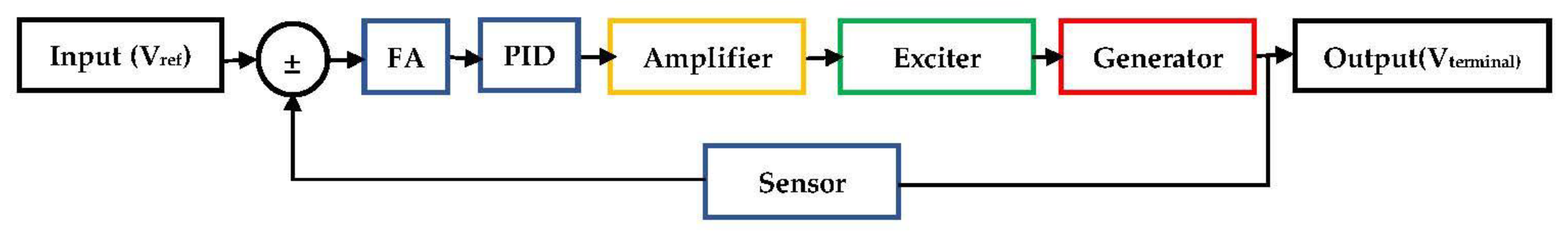
The fuzzy-adaptive-proportional-integral-derivative (FAPID)-based AVR was established by adding the fuzzy adaptive circuit (FA) in series with the traditional PID controller, as shown in Figure 4. As the standard PID is given to the output of the fuzzy controller as an input, the differences between the generator’s actual and reference terminal voltages as well as their derivatives serve as the FA’s two inputs. Accordingly, the input to the PID is continuously changed based on the rules of the FA, producing an online auto-tuned signal to the PID to deal with any change in the AVR and improve dynamic and steady-state performance. Table 1 shows an example of membership function rules used for fuzzy output based on the input error and changes in error signals [82]. The entire controller is referred to as a fuzzy adaptive optimized proportional-integral-derivative controller (FAOPID) when the FA is utilized with an optimized PID controller.
The authors of [83] improved the AVR transient response by using FA control. In [84], a FAPID filter initialized by the TLBO algorithm was presented to the AVR control system. Comparison studies were conducted with the FAPID and the classical PID to show the improvement gained from using the TLBO algorithm. In [85], the FA was used to improve the load frequency control with AVR for single- and two-area systems. The authors of [86] used TLBO to tune the FAPID and proved its superiority through comparisons with the PSO and firefly algorithms. The FAPID-based AVR was robust against changes in the model time constant. The hybrid GA-PSO technique was introduced to tune fuzzy-P-, fuzzy-I-, and fuzzy-D-based AVRs in [87]. This hybrid method outperformed FAPID and classical PID controllers. The auto-tuned FAPID AVR system with PID gains optimized by equilibrium optimization (EO) [88] outperformed the classical PID with optimized gains using whale optimization (WO), the PIDA with gains optimized by WO [89], the PIDA optimized by TLBO [90], and the PI with gains optimized by EO [91].
This detailed review has shown that all researchers worked on enhancing AVR system performance and stability indicators such as the maximum overshoot and the rise and settling times as well as the steady-state error under certain objective functions. Nevertheless, the instant response of the AVR control system to dynamic changes without affecting system stability indicators was not tackled, and this is one of the objectives of this paper.
3. Mathematical Modeling
3.1. Mathematical Background
Since the fractional-order system response eventually converges to the integer-order response of the system, the fractional differential equations have recently attracted a lot of attention. Fractional derivatives have benefits of being more flexible in the model and being a great tool for describing transient responses of real-world systems. Assuming that ϕ > 0, t > a, α, a, t ∈ R, the fractional operator (Dtϕ) is defined as [92,93]:
where Dtϕ is called the Caputo fractional derivative or Caputo fractional differential operator of order ϕ and NR is the set of positive integer numbers. Let us assume the following nonlinear dynamical system driven by the Caputo fractional derivative and order ϕ ∈ (n−1, n]:
where f and λ: are functions satisfying the Lipschitz condition by f(t, x), λ(x) referred to x(t), and a unique solution for Equation (19) on interval exists. To find the general solution of this dynamic system, a Laplace transform is applied to Equation (19) as:
In the case of ϕ∈ (0, 1], the equation is simplified into:
If we take the inverse Laplace transform and apply convolution theory, Equation (21) becomes:
where Γ is the gamma function. Moreover, an approximated solution for Equation (21) can be interpreted by using continued fraction expansion approximations [94] for the term ( as:
To control the dynamical system in Equation (19) using the control function u(t), the system takes the following form:
with a general solution:
3.2. OPIDMR-FA-Based AVR Dynamic System Model
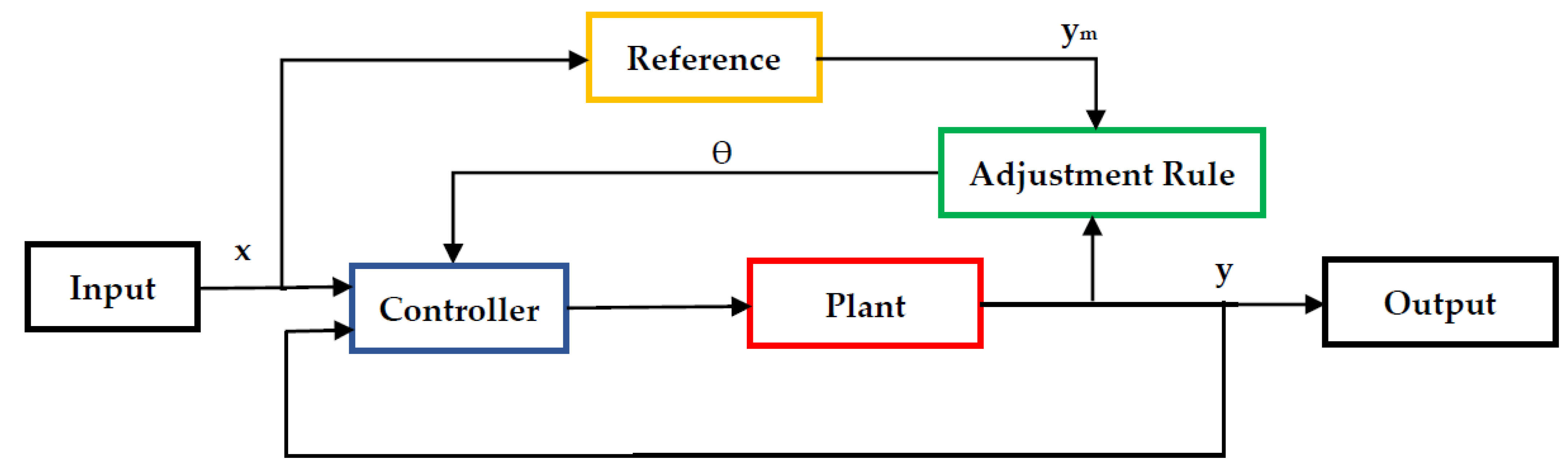
One of the primary methods for adaptive control is the model reference adaptive system (MRA), in which the desired performance is expressed in terms of a reference model. The reference model describes the desired input–output characteristics of the closed-loop system. Consequently, the controller parameters are updated in response to the difference between the output of the reference model and the output of the system [95]. Figure 5 illustrates the MRA control system, where two loops are used: an inner loop that gives the typical control feedback and an outer loop that modifies the inner loop’s parameters.
The gradient method of MRA was utilized for this study to handle the computation of sensitive derivatives. The main idea of the MRA is based on quasi-stationary treatment analysis, and the system behaves to minimize a certain objective function (J). If J is defined by:
where e is the tracking error, y is the output from the system, and ym is the reference, the rate of change in the updated parameter (θ) is adjusted in the direction of the negative gradient of J with a designing gain (𝜆) as follows:
The derivative ∂e/∂θ is evaluated by considering θ as a fixed value.
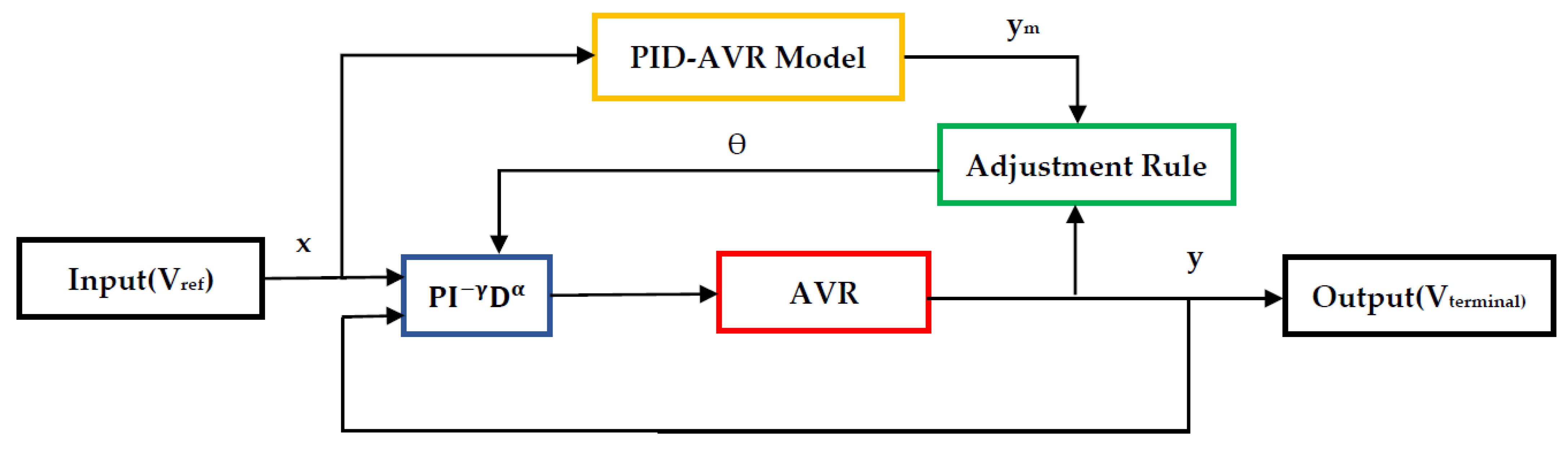
We applied the MRA to the AVR system, as indicated in Figure 6. The PID-based AVR model was utilized as a reference model, and the PID design parameters and were selected using a suitable optimizer. Then, a FOPID controller was employed for the inner loop with design parameters . The resulting system can be called optimized proportional-integral-derivative model reference fractional adaptive (OPIMR-FA)-based AVR. We generated the mathematical model of the system in the Laplace domain after making all possible simplifications to take the form:
where x(s) and y(s) are the per-unit (p.u.) reference and terminal voltages, respectively.
The novel adaptive controller used in Equations (28) and (29) converts the AVR system from a linear system, as indicated in Equation (2), to a nonlinear control system, with the system-governing differential equation using the inverse Laplace transform and proper mathematical simplifications written as:
where , and are the controller design parameters to minimize the objective function (J). At a steady state, all terms containing the error (e) tend to zero and the system stability is satisfied. The OPIDMR-FA-based AVR system stability is sustained during design under the negative real part of the system roots calculated from the system characteristic equation defined by:
4. Results and Discussion
The dynamic response of the proposed OPIDMR-FA-controller-based AVR system was evaluated and compared with recently presented controllers, PID, PIDA, and FAOPID, under different input reference voltage signals. The integral of square error (ISE) was used as an objective function for all optimizers due to having a minimal maximum overshoot and the least difficult analytical formula. All systems governing differential equations were solved numerically using the Runge–Kutta method, implemented in MATLAB SIMULINK, with a variable time-step for efficient computation, where the standard solver ODE45 was employed. The OPIDMR-FA controller design parameters were selected using trial-and-error estimations, while its PID gains were selected by using the whale optimization algorithm (WO).
In the case of a PID controller, the CSO, MFO, WCA, TLBO, HCO, and WO optimizers [54] were used for tuning, while the WO and TLBO algorithms were used to tune the PIDA controller [89,90]. Moreover, the FAOPID-based AVR system employed the EO algorithm for setting its PID gain values [88]. The time constants and gain of the main components of the AVR system under study are indicated in Table 2. Four cases were studied. The first case used a 1 p.u. step-change on the voltage reference, the second case used a 1.1 p.u. step-change on the voltage reference, while the third case used a 0.9 p.u. step-change on the voltage reference. Finally, a dynamic voltage reference signal was used in the fourth case.
4.1. Case Study 1
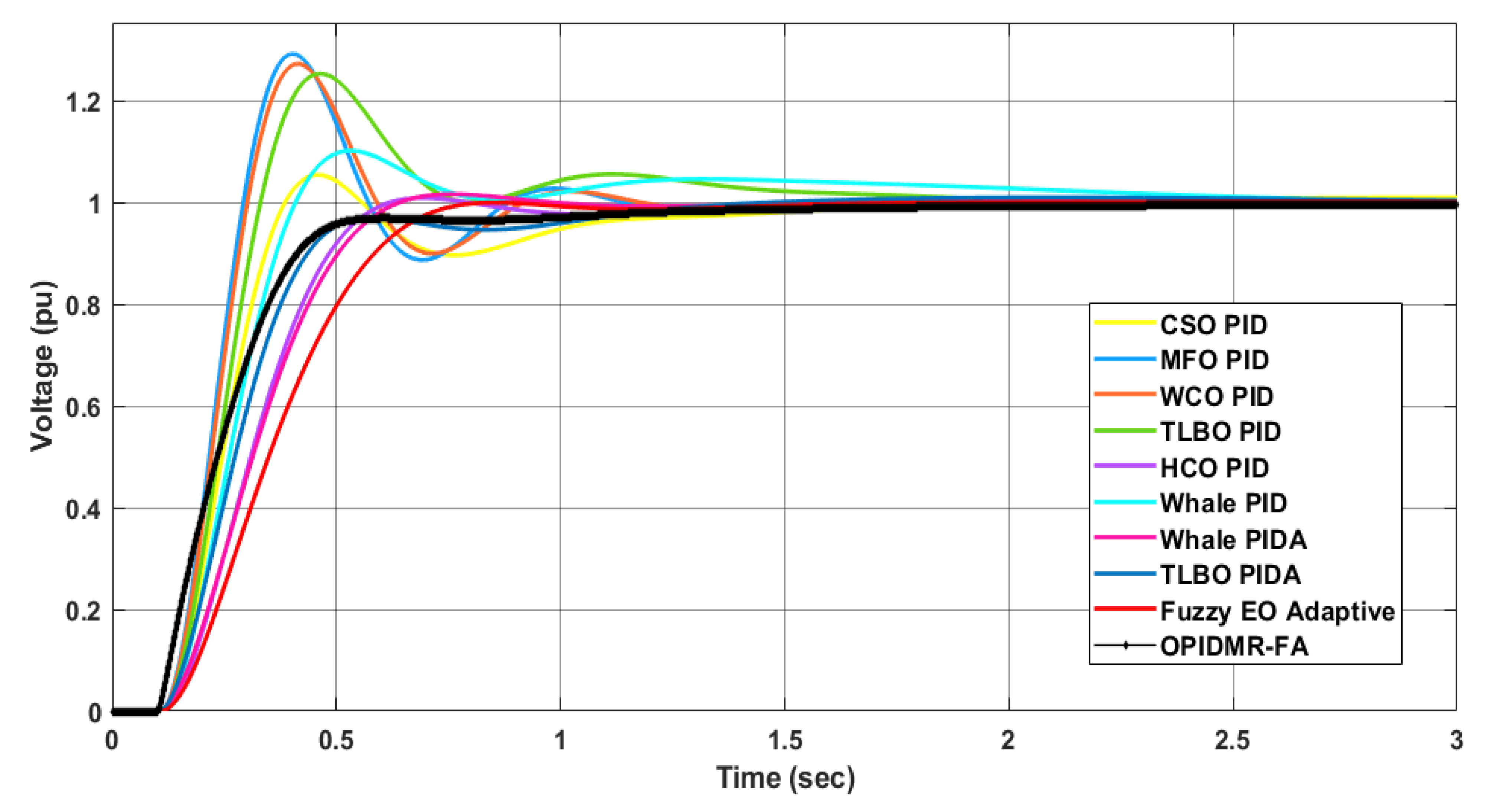
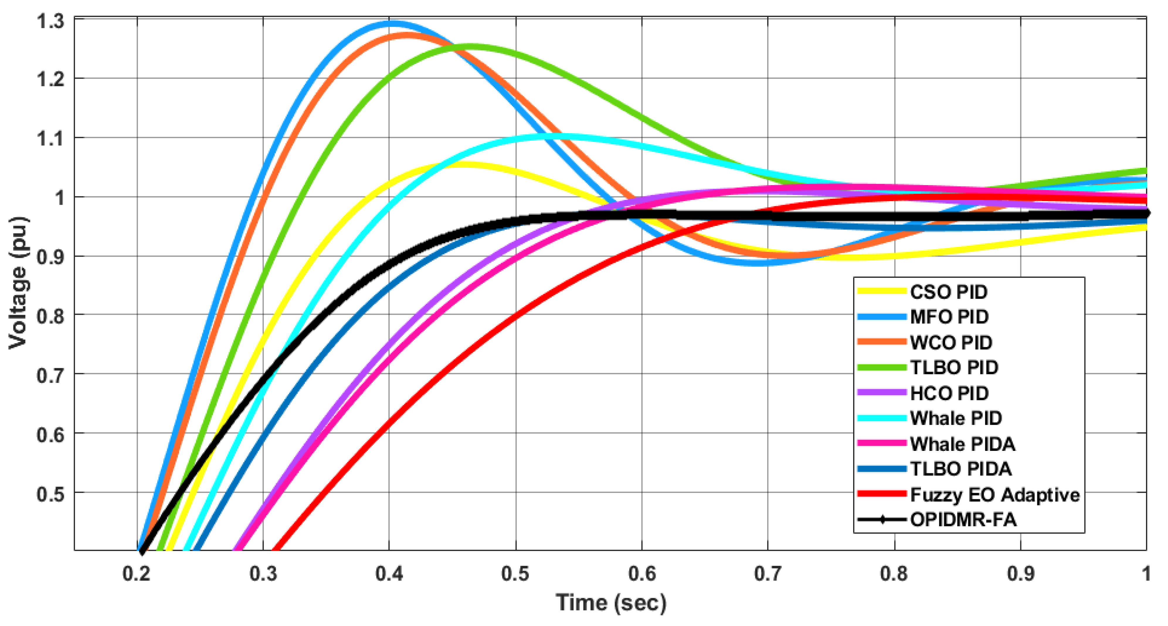
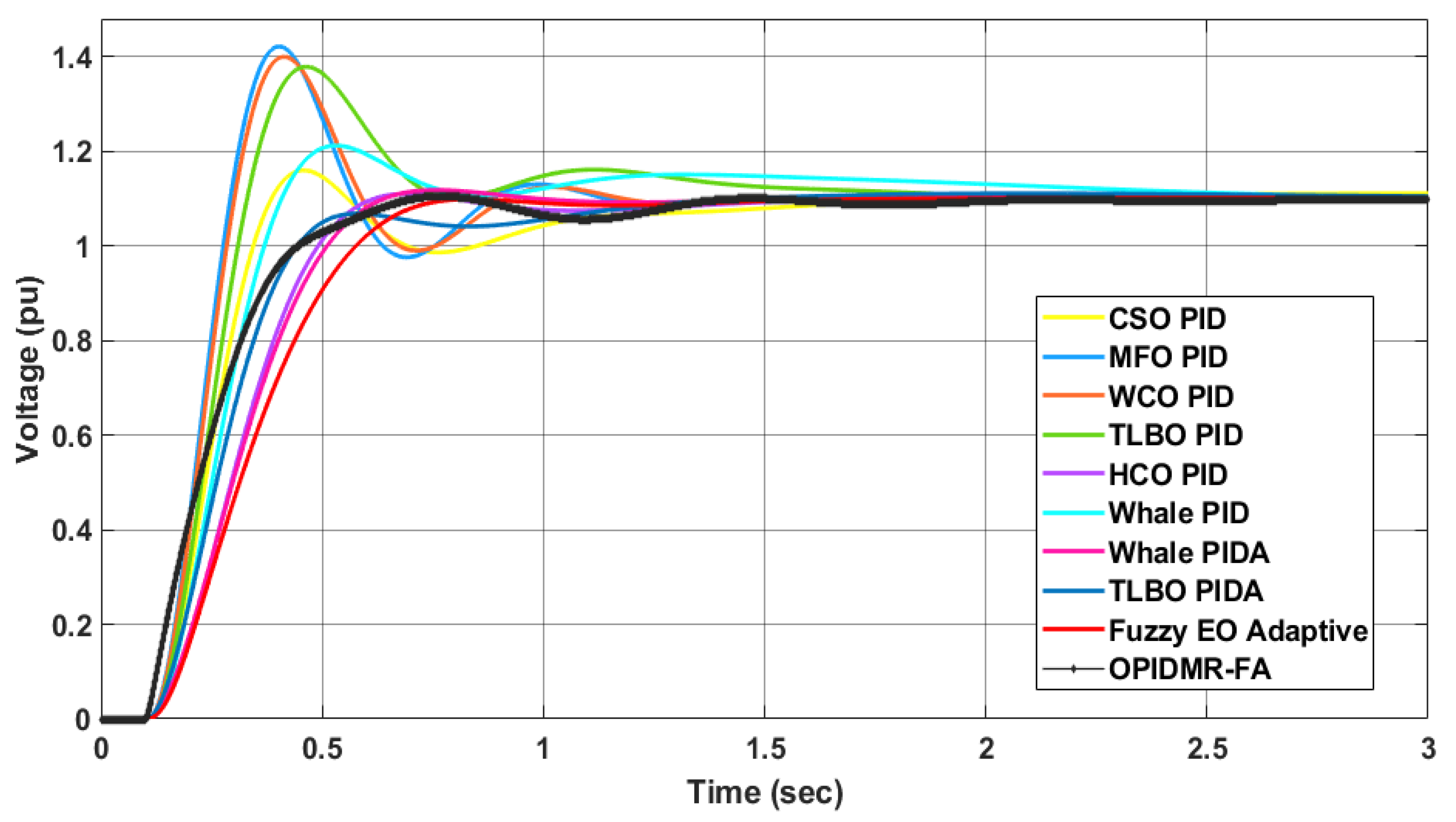
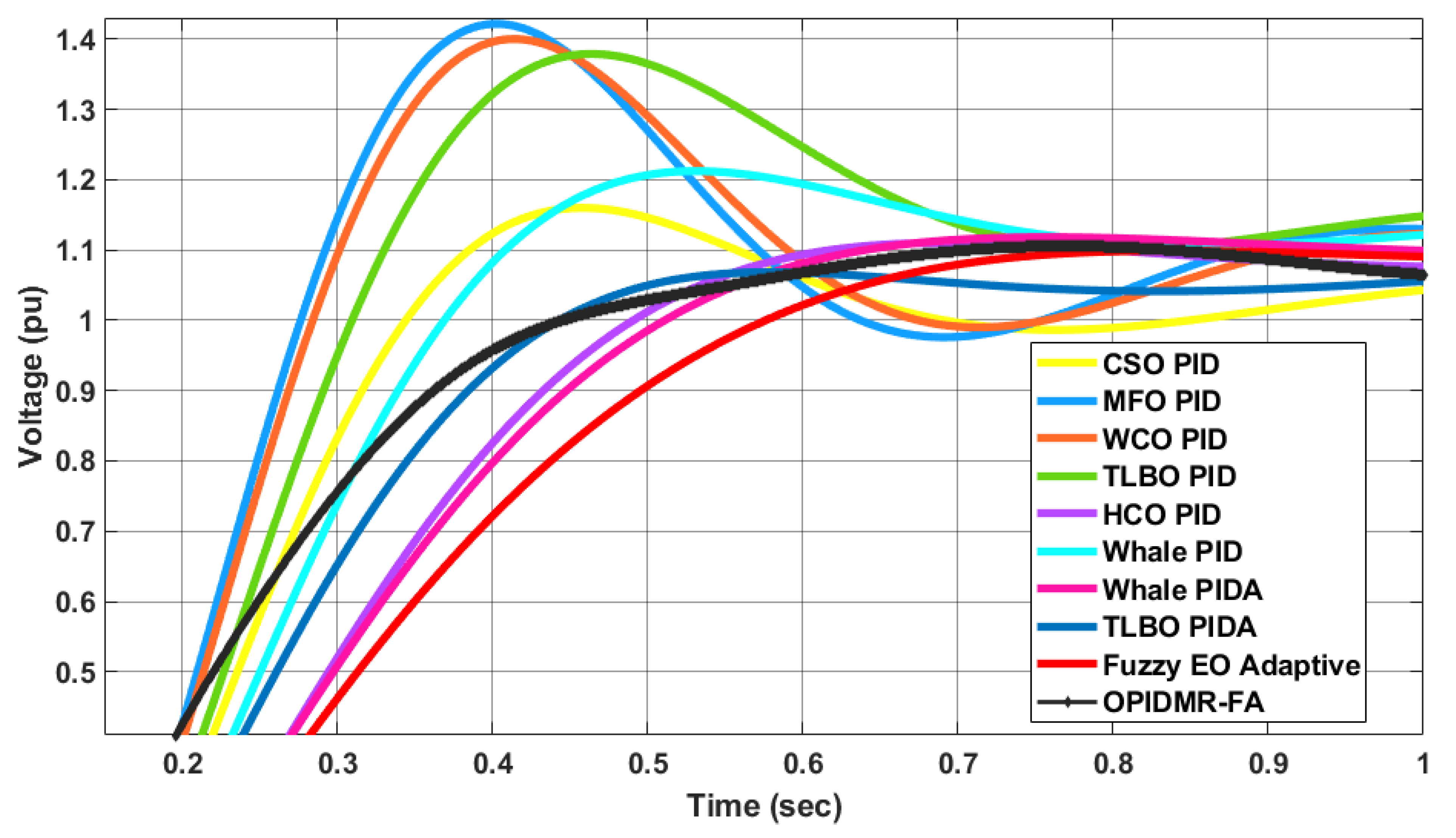
As mentioned before, in this case a 1 p.u. step-change on the voltage reference was used. Figure 7 and Figure 8 show the transient response of the AVR system using different control systems. Table 3 indicates the rise time, settling time, and maximum overshoot of each controller.
It is obvious that the proposed OPIDMR-FA controller gave a very smooth response without an overshoot or oscillations. In addition, the average response speed of the OPIDMR-FA controller was between the optimized PID and optimized PIDA controllers. The OPIDMR-FA offered an intermediate value for the rise time, which was equal to 0.4049 s and came after the HCO PID controller, as indicated in Table 3 and Figure 8. Therefore, the overall dynamic response of the AVR system utilizing the proposed OPIDMR-FA controller was superior to the other controllers in the case of a 1 p.u. step reference.
4.2. Case Study 2
In this case, a 1.1 p.u. step-change on the voltage reference was used. Figure 9 and Figure 10 illustrate all controllers’ responses in this case.
It is shown that the dynamic response of the proposed OPIDMR-FA had a maximum overshoot that was 9.5% lower than the CSO PID, 38% lower than the MFO PID, 33.33% lower than the WCO PID, 31.4% lower than the TLBO PID, 4.76% lower than the HCO PID, 15.24% lower than the whale PID, and slightly better than the Whale PIDA, TLBO PIDA, and Fuzzy EO PID.
4.3. Case Study 3
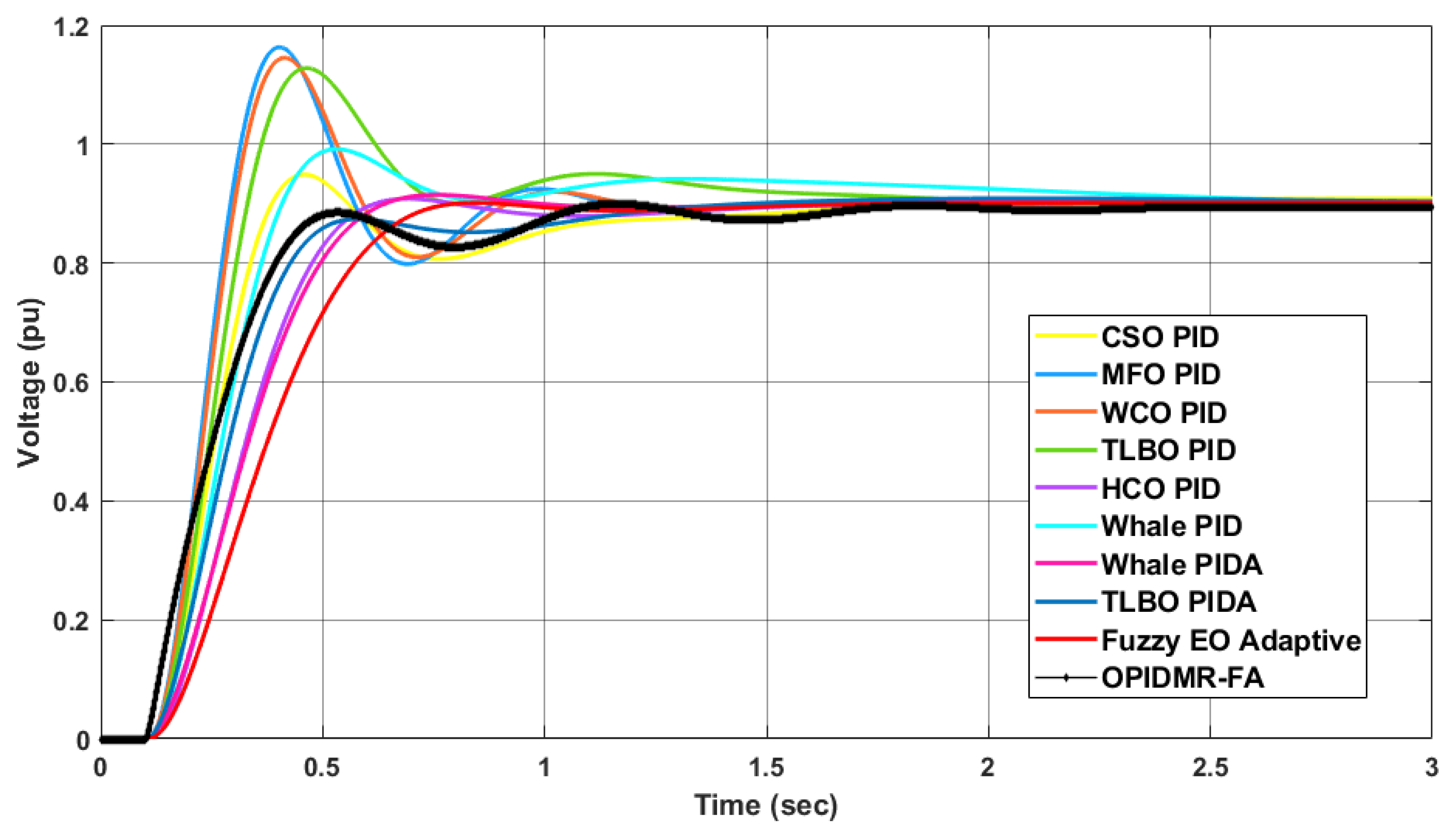
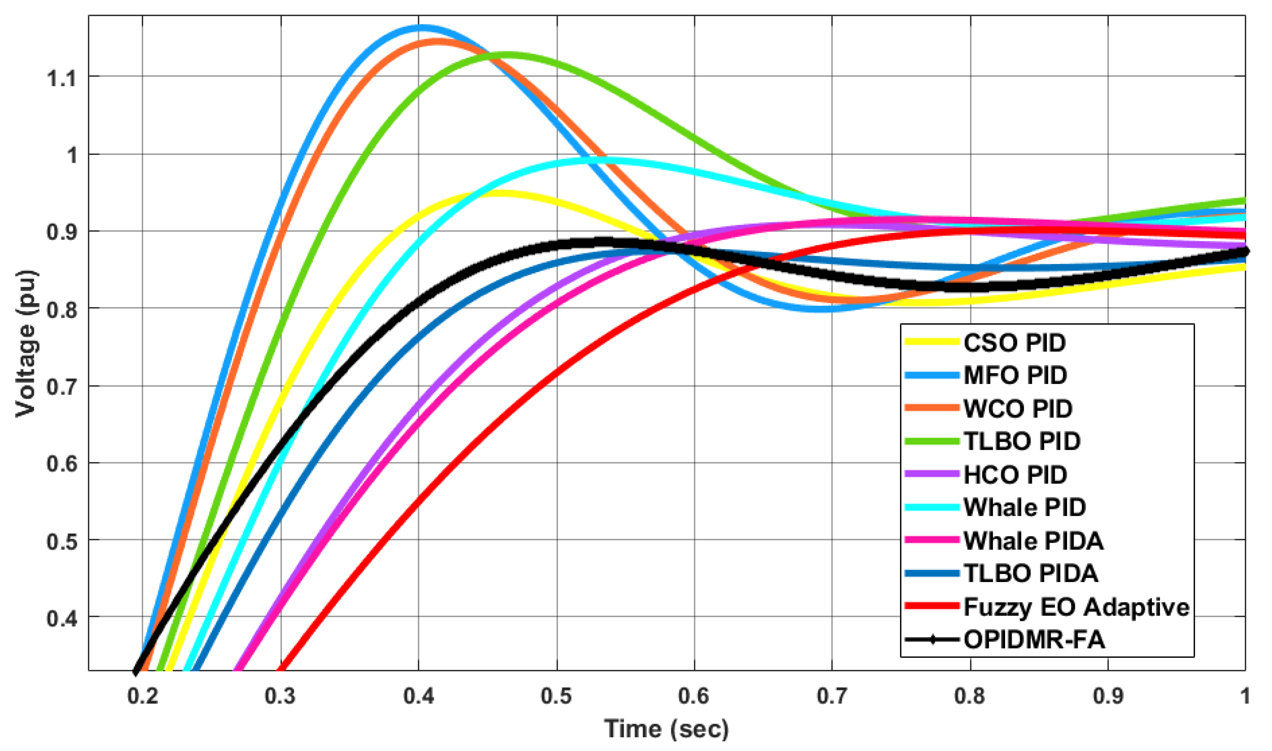
In this case, a 0.9 p.u. step-change on the voltage reference was used. Figure 11 and Figure 12 demonstrate the transient responses of all controllers in this case.
Again, the proposed OPIDMR-FA had a maximum overshoot that was 5.5% lower than the CSO PID, 32.2% lower than the MFO PID, 27.7% lower that the WCO PID, 26.6% lower than the TLBO PID, 3.3% lower than the HCO PID, and 11.11% lower than the whale PID. In addition, the dynamic response of the OPIDMR-FA was slightly better than the whale PIDA, TLBO PIDA, and fuzzy EO PID.
4.4. Case Study 4
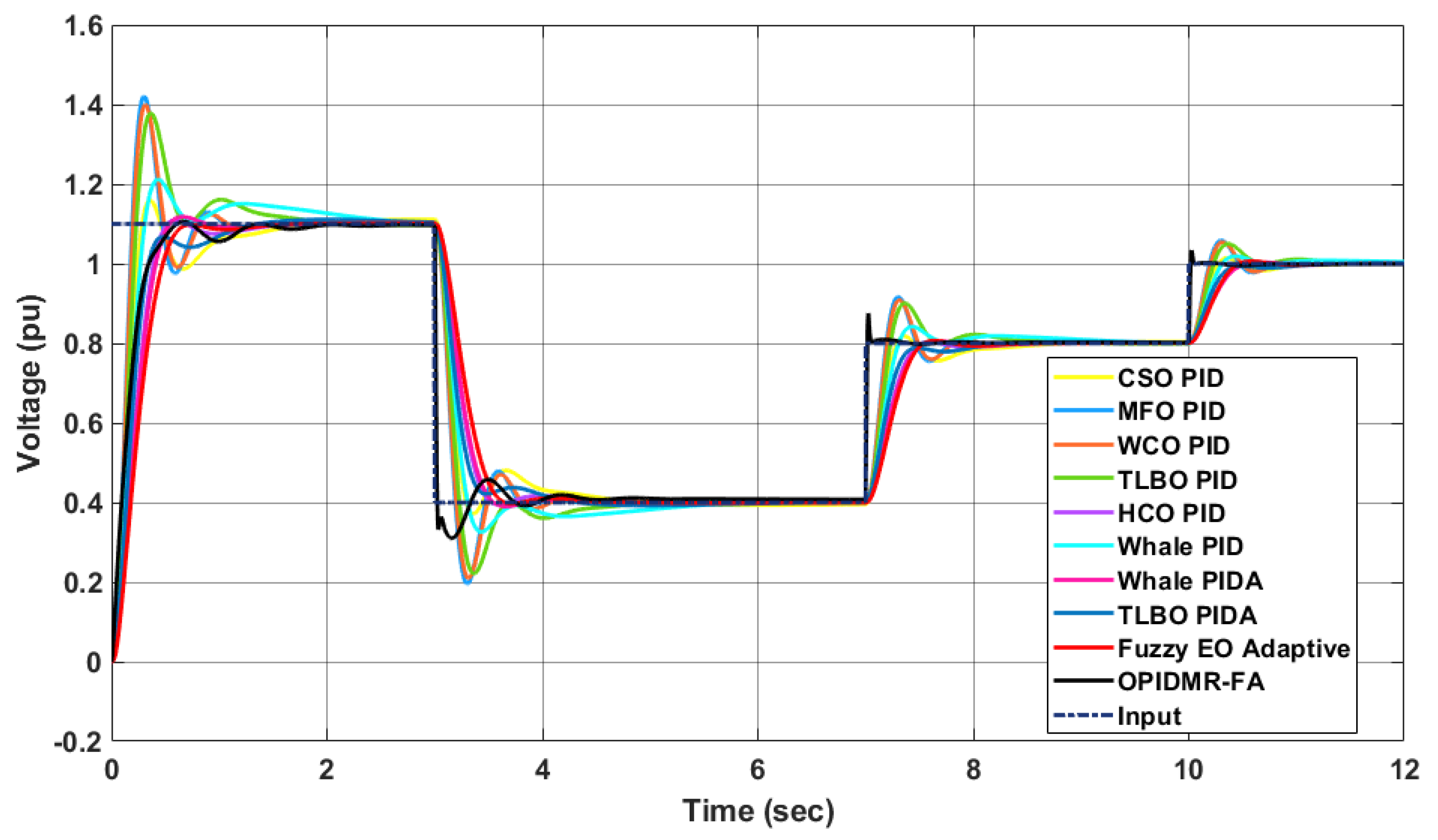
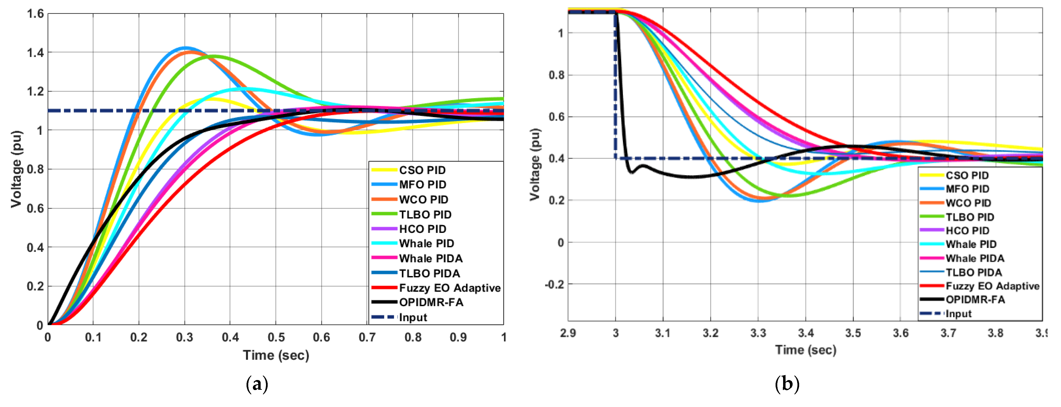
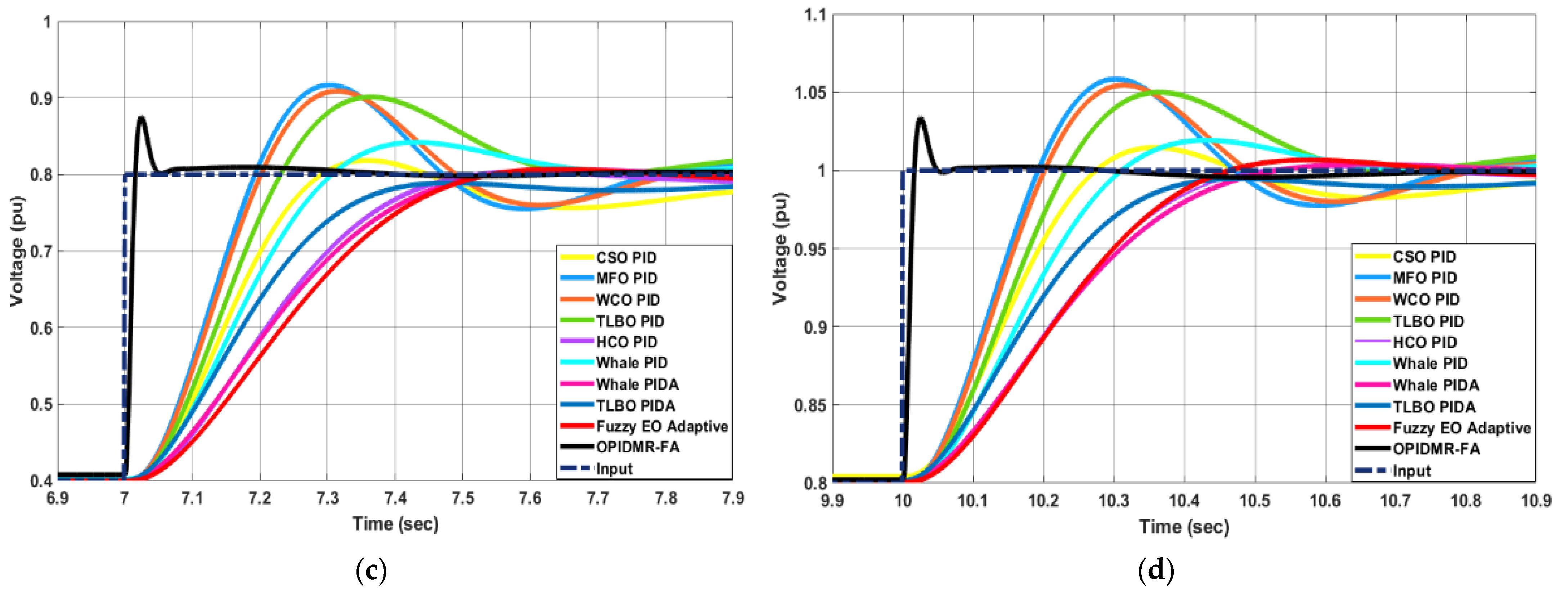
In this case, a dynamic change in the voltage reference was used. Figure 13 and Figure 14 demonstrate the transient responses of all controllers in this case.
These results show that the proposed OPIDMR-FA controller succeeded in tracking the first step-change with an average speed between the other controllers, while during the other three step-changes of the reference voltage, the OPIDMR-FA controller instantly tracked the reference signal faster than the other controllers in terms of rise and settling times.
Therefore, the proposed OPID-MRFA controller is sensitive to dynamic step-changes in the reference voltage of the AVR.
5. Conclusions
In this paper, a survey of various AVR control systems was presented. Afterward, a novel OPIDMR-FA was suggested and evaluated against other controllers that were recently presented in the literature. The OPIDMR-FA controller succeeded in tracking the input signal smoothly without overshooting and reacted instantly to changes in the reference voltage signal for the AVR system compared to the other controllers. Moreover, the dynamic response of the proposed OPIDMR-FA was characterized by a maximum overshoot that was lower than the overshoots of the CSO PID, MFO PID, WCO PID, TLBO PID, and HCO PID by 5–9%, 32–38%, 27–33%, 26–31%, and 3–4%, respectively. Furthermore, the maximum overshoot observed when the proposed OPIDMR-FA was utilized for AVR was lower than the whale PID by 11–15%, which was slightly better than the whale PIDA, TLBO PIDA, and Fuzzy EO PID. As a result, the suggested controller offers an immediate response and can follow quick changes in the set point. For future work, the proposed controller will be applied to a nonlinear model of an AVR system. In addition, system parameter uncertainties should be considered.
Funding
This research received no external funding.
Data Availability Statement
Not applicable.
Conflicts of Interest
The authors declare no conflict of interest.
References
- Ula, A.; Hasan, A. Design and implementation of a personal computer based automatic voltage regulator for a synchronous generator. IEEE Trans. Energy Convers. 1992, 7, 125–131. [Google Scholar] [CrossRef]
- Kiam, A.H.; Chong, G.; Yun, L. PID control system analysis, design, and technology. IEEE Trans. Control Syst. Technol. 2005, 13, 559–576. [Google Scholar] [CrossRef] [Green Version]
- Petras, I. The fractional—Order controllers: Methods for their synthesis and application. Electr. Eng. J. 1999, 50, 284–288. [Google Scholar]
- Godjevac, J. Comparison between PID and fuzzy control. In Ecole Polytechnique Fédérale de Lausanne, Département d’Informatique, Laboratoire de Microinformatique, Internal Report 93; Ecole Polytechnique Fédérale de Lausanne: Lausanne, Switzerland, 1997. [Google Scholar]
- Mallesham, G.; Rajani, A. Automatictuning of PID controller using fuzzy logic. In Proceedings of the 8th International Conference on Development and Application Systems, Suceava, Romania, 25–27 May 2006. [Google Scholar]
- Jung, S.; Dorf, R. Analytic PIDA Controller Design Technique for A Third Order System. In Proceedings of the 35th Conference on Decision and Control Kobe, Kobe, Japan, 13 December 1996; Volume 3, pp. 2513–2518. [Google Scholar]
- Kumar, V.; Mittal, A.P. Parallel fuzzy P + fuzzy I + fuzzy D controller: Design and performance evaluation. Int. J. Autom. Comput. 2010, 7, 463–471. [Google Scholar] [CrossRef]
- Holland, J.H. Adaptation in Natural and Artificial Systems; University Michigan Press: Ann Arbor, MI, USA, 1975. [Google Scholar]
- Goldberg, D.E. Genetic Algorithms in Search Optimization and Machine Learning; Addison Wesley Publishers: Edmonton, AB, Canada, 1989. [Google Scholar]
- Bhati, S.; Nitnawwre, D. Genetic Optimization Tuning of an Automatic Voltage Regulator System. Int. J. Sci. Eng. Technol. 2012, 1, 120–124. [Google Scholar]
- Divya, K.; Seshadri, G. GA-PID tuned Stabilizer AVR system for Synchronous Generators. Int. J. Innov. Technol. 2015, 3, 438–442. [Google Scholar]
- Oonsivilai, A.; Pao-La-Or, P. Application of Adaptive Tabu Search for Optimum PID Controller Tuning AVR System. WSEAS Trans. Power Syst. 2008, 6, 495–506. [Google Scholar]
- Puangdownreong, D.; Sujitjorn, S.; Kulworawanichpong, T. Convergence Analysis of Adaptive Tabu Search. Int. J. Sci. Asia 2004, 38, 183–190. [Google Scholar] [CrossRef]
- Chaiyaratana, C.; Zalzala, A.M.S. Recent Developments in Evolutionary and Genetic Algorithms: Theory and Applications. In Proceedings of the 2nd International Conference on Genetic Algorithms in Engineering System: Innovations and Applications, Glasgow, UK, 2–4 September 1997; Volume 2, pp. 270–277. [Google Scholar]
- Puangdownreong, D.; Areerak, K.-N.; Srikaew, A.; Sujitjorn, S.; Totarong, P. System Identification via Adaptive Tabu Search. In Proceedings of the 2002 IEEE International Conference on Industrial Technology, Bankok, Thailand, 11–14 December 2002; Volume 2, pp. 915–920. [Google Scholar]
- Puangdownreong, D. Multiobjective Multipath Adaptive Tabu Search for Optimal PID Controller Design. Int. J. Intell. Syst. Appl. 2015, 7, 51–58. [Google Scholar] [CrossRef] [Green Version]
- Sujitjorn, S.; Kulworawanichpong, T. Adaptive Tabu Search and Applications in Engineering Design. In Artificial Intelligent and Applications; IOS Press: Amsterdam, The Netherlands, 2006. [Google Scholar]
- Deacha, P.; Jukkrit, K.; Sarawut, S. Multipath adaptive Tabu search: Its convergence and application to identification problem. J. Phys. Sci. 2012, 7, 5288–5296. [Google Scholar]
- Auttarat, N.; Tunyasrirut, S.; Puangdownreong, D. Application of intensified current search to optimum PID controller design in AVR system. In Asian Simulation Conference; Springer: Berlin/Heidelberg, Germany, 2014; pp. 255–266. [Google Scholar]
- Madasamy, G.; Ravichandran, C. Optimal Tuning of PID controller by Bat Algorithm in an Automatic Voltage Regulator System. Int. J. Innov. Sci. Eng. Technol. 2015, 2, 336–339. [Google Scholar]
- Yang, X. A New Meta-Heuristic Bat-Inspired Algorithm; González, J.R., et Pelta, D.A., Cruz, C., Terrazas, G., Krasnogor, N., Eds.; NICSO 2010: Granada, Spain, 2010; pp. 65–74. [Google Scholar]
- Sambariya, D.; Gupta, R.; Prasad, R. Design of optimal input-output scaling factors based fuzzy PSS using bat algorithm. Eng. Sci. Technol. Int. J. 2016, 19, 991–1002. [Google Scholar] [CrossRef] [Green Version]
- Fister, I., Jr.; Fong, S.; Brest, J. A novel hybrid self-adaptive bat algorithm. Sci. World J. 2014, 2014, 12. [Google Scholar] [CrossRef] [PubMed] [Green Version]
- Sambariya, D.K.; Manohar, H. Model order reduction by integral squared error minimization using bat algorithm. In Proceedings of the IEEE 2015 RAECS UIET Panjab University Chandigarh, Chandigarh, India, 21–22 December 2015; pp. 1–7. [Google Scholar]
- Gaing, Z.L. A particle swarm optimization approach for optimum design of PID controller in AVR system. IEEE Trans. Energy Convers. 2004, 19, 384–391. [Google Scholar] [CrossRef] [Green Version]
- Kennedy, J.; Eberhart, R. Particle swarm optimization. In Proceedings of the IEEE International Conference on Neural Network, Perth, WA, Australia, 27 November–1 December 1995; pp. 1942–1948. [Google Scholar]
- Shi, Y.; Eberhart, R. A modified particle swarm optimizer. In Proceedings of the Congress on Evolutionary Computation, Anchorage, AK, USA, 4–9 May 1998; pp. 69–73. [Google Scholar]
- Kashki, M.; Abdel-Magid, Y.L.; Abido, M.A. A reinforcement learning automata optimization approach for optimum tuning of PID controller in AVR system. In International Conference on Intelligent Computing; Springer: Berlin/Heidelberg, Germany, 2008; pp. 684–692. [Google Scholar]
- Howell, M.; Best, M. On-Line PID Tuning for Engine Idle-Speed Control Using Continuous Action Reinforcement Learning Automata. Control Eng. Pract. 2000, 8, 147–154. [Google Scholar] [CrossRef] [Green Version]
- Howell, M.; Gordon, T. Continuous Action Reinforcement Learning Automata and their Application to Adaptive Digital Filter Design. Eng. Appl. Artif. Intell. 2001, 14, 549–562. [Google Scholar] [CrossRef]
- Kashki, M.; Abdel-Magid, Y.; Abido, M. Application of novel reinforcement learning automata approach in power system regulator. J. Circuits Syst. Comput. 2009, 18, 1609–1625. [Google Scholar] [CrossRef]
- Hwang, C.C.; Lyu, L.Y.; Liu, C.T.; Li, P.L. Optimal design of an SPM motor using genetic algorithms and Taguchi method. IEEE Trans. Magn. 2008, 44, 4325–4328. [Google Scholar] [CrossRef]
- Hasanien, H.M. Design Optimization of PID Controller in Automatic Voltage Regulator System Using Taguchi Combined Genetic Algorithm Method. IEEE Trans. 2012, 7, 825–831. [Google Scholar] [CrossRef]
- Shayeghi, H.; Dadashpour, J. Anarchic Society Optimization Based PID Control of an Automatic Voltage Regulator (AVR) System. Electr. Electron. Eng. 2012, 2, 199–207. [Google Scholar] [CrossRef] [Green Version]
- Ahmadi-Javid, A. Anarchic society optimization: A human-inspired method, Applied Soft Computing. In Proceedings of the IEEE Congress on Evolutionary Computation, New Orleans, LA, USA, 5–8 June 2011; pp. 2586–2592. [Google Scholar]
- Gozde, H.; Taplamacioglu, M.; Kocaarslan, I. Application of Artificial Bees Colony algorithm in an Automatic Voltage Regulator (AVR) system. Int. J. Tech. Phys. Probl. Eng. 2010, 2, 88–92. [Google Scholar]
- Karaboga, D. An Idea Based on Honey Bee Swarm for Numerical Optimization; Technical Report-TR06; Erciyes University of Engineering, Faculty of Computer Engineering Department: Kayseri, Turkey, 2005. [Google Scholar]
- Karaboga, D.; Basturk, B. A powerful and efficient algorithm for numeric optimization: Artificial bee colony (ABC) algorithm. J. Glob. Optim. 2007, 3, 459–471. [Google Scholar] [CrossRef]
- Gozde, H.; Taplamacioglu, M. Comparative performance analysis of artificial bee colony algorithm for automatic voltage regulator (AVR) system. J. Frankl. Inst. 2011, 348, 1927–1946. [Google Scholar] [CrossRef]
- Li, C.; Li, H.; Kou, P. Piecewise function based gravitational search algorithm and its application on parameter identification of AVR system. Neurocomputing 2014, 124, 139–148. [Google Scholar] [CrossRef]
- Rashedi, E.; Nezamabadi-Pour, H.; Saryazdi, S. GSA: A gravitational search algorithm. Inf. Sci. 2009, 179, 2232–2248. [Google Scholar] [CrossRef]
- Duman, S.; Yörükeren, N.; Altaş, İ.H. Gravitational search algorithm for determining controller parameters in an automatic voltage regulator system. Turk. J. Electr. Eng. Comput. Sci. 2016, 24, 2387–2400. [Google Scholar] [CrossRef] [Green Version]
- Panda, S.; Sahu, B.; Mohanty, P. Design and performance analysis of PID controller for an automatic voltage regulator system using simplified particle swarm optimization. J. Frankl. Inst. 2012, 349, 2609–2625. [Google Scholar] [CrossRef]
- Pedersen, M.; Chipperfield, A. Simplifying particle swarm optimization. Appl. Soft Comput. 2010, 10, 618–628. [Google Scholar] [CrossRef]
- Alfi, A.; Modares, H. System identification and control using adaptive particle swarm optimization. Appl. Math. Model. 2011, 35, 1210–1221. [Google Scholar] [CrossRef]
- Nirmal, J.F.; Auxillia, D.J. Adaptive PSO based Tuning of PID Controller for an Automatic Voltage Regulator System. In Proceedings of the 2013 International Conference on Circuits, Power and Computing Technologies (ICCPCT), Nagercoil, India, 20–21 March 2013. [Google Scholar]
- Mohanty, P.K.; Sahu, B.K.; Panda, S.; Kar, S.K.; Mishra, N. Performance Analysis and Design of Proportional Integral Derivative Controlled Automatic Voltage Regulator System Using Local Unimodal Sampling Optimization Technique. In International Conference on Swarm, Evolutionary, and Memetic Computing; Springer: Berlin/Heidelberg, Germany, 2012; pp. 566–576. [Google Scholar]
- Pedersen, M.E.H.; Field, A.J.C. Local Unimodal Sampling; Technical Report number HL0801; Hvass Laboratories, 2008. [Google Scholar]
- Bendjeghaba, O.; Boushaki, S. Optimal Tuning of PID Controller in Automatic Voltage Regulator System using Improved Harmony Search Algorithm. In Proceedings of the 7th Global Conference on Power Control and Optimization, Prague, Czech, 25 August 2013. [Google Scholar]
- Geem, Z.W.; Kim, J.H.; Loganathan, G.V. A new heuristic optimization algorithm: Harmony search. Simulation 2001, 76, 60–68. [Google Scholar] [CrossRef]
- Yadav, P.; Kumar, R.; Panda, S.; Chang, C. An intelligent tuned harmony search algorithm for optimization. Inf. Sci. 2012, 196, 47–72. [Google Scholar] [CrossRef]
- Fourie, J.; Mills, S.; Green, R. Harmony filter: A robust visual tracking system using the improved harmony search algorithm. Image Vis. Comput. 2010, 28, 1702–1716. [Google Scholar] [CrossRef]
- Pachauri, N. Water cycle algorithm-based PID controller for AVR. COMPEL-Int. J. Comput. Math. Electr. Electron. Eng. 2020, 39, 551–567. [Google Scholar] [CrossRef]
- Rais, M.C.; Dekhandji, F.Z.; Recioui, A.; Rechid, M.S.; Djedi, L. Comparative Study of Optimization Techniques Based PID Tuning for Automatic Voltage Regulator System. Eng. Proc. 2022, 14, 21. [Google Scholar]
- Rao, R.; Savsani, V.; Vakharia, D. Teaching-learning based optimization: A novel optimization method for continuous non-linear large scale problems. Inf. Sci. J. 2012, 183, 1–15. [Google Scholar] [CrossRef]
- Priyambada, S.; Mohanty, P.; Sahu, B. Automatic Voltage Regulator using TLBO algorithm optimized PID controller. In Proceedings of the 9th International Conference on Industrial and Information Systems, Gwalior, India, 15–17 December 2014. [Google Scholar]
- Chatterjee, S.; Mukherjee, V. PID controller for automatic voltage regulator using teaching–learning based optimization technique. Electr. Power Energy Syst. 2016, 77, 418–429. [Google Scholar] [CrossRef]
- Juang, C.F. A hybrid of genetic algorithm and particle swarm optimization for recurrent network design. IEEE Trans. Syst. Man Cybern. Part B 2004, 34, 997–1006. [Google Scholar] [CrossRef]
- Kim, D.H.; Park, J.I. Intelligent PID Controller Tuning of AVR System Using GA and PSO. In International Conference on Intelligent Computing; Springer: Berlin/Heidelberg, Germany, 2005. [Google Scholar]
- Kim, D.; Cho, J. A Biologically Inspired Intelligent PID Controller Tuning for AVR Systems. Int. J. Control Autom. Syst. 2006, 4, 624–636. [Google Scholar] [CrossRef]
- Passino, K.M. Biomimicry of Bacterial Foraging for Distributed Optimization; University Press: Princeton, NJ, USA, 2001. [Google Scholar]
- Kim, D.H.; Cho, J.H. Intelligent control of AVR system using GA-BF. In Lecture Notes in Computer Science Proceeding of Springer Melbourne; Springer: Berlin/Heidelberg, Germany, 2005. [Google Scholar]
- Kansit, S.; Assawinchaichote, W. Optimization of PID Controller based on PSOGSA for an Automatic Voltage Regulator System. Procedia Comput. Sci. 2016, 86, 87–90. [Google Scholar] [CrossRef] [Green Version]
- Mirjalili, S.; Hashim, S.Z.M. A New Hybrid PSOGSA Algorithm for Function Optimization. In Proceedings of the Computer and Information Application (ICCIA), Tianjin, China, 3–5 December 2010; pp. 374–377. [Google Scholar]
- Fayek, H.H.; Rusu, E. Novel Combined Load Frequency Control and Automatic Voltage Regulation of a 100% Sustainable Energy Interconnected Microgrids. Sustainability 2022, 14, 9428. [Google Scholar] [CrossRef]
- Dehghani, M.; Mardaneh, M.; Guerrero, J.M.; Malik, O.P.; Ramirez-Mendoza, R.A.; Matas, J.; Vasquez, J.C.; Parra-Arroyo, L. A new “Doctor and Patient” optimization algorithm: An application to energy commitment problem. Appl. Sci. 2020, 10, 5791. [Google Scholar] [CrossRef]
- Oladipo, S.; Sun, Y.; Wang, Z. An effective hFPAPFA for a PIDA-based hybrid loop of load frequency and terminal voltage regulation system. In Proceedings of the 2021 IEEE PES/IAS PowerAfrica, Nairobi, Kenya, 23–27 August 2021; pp. 1–5. [Google Scholar]
- Abdel-Basset, M.; Shawky, L.A. Flower pollination algorithm: A comprehensive review. Artif. Intell. Rev. 2019, 52, 2533–2557. [Google Scholar] [CrossRef]
- Yapici, H.; Cetinkaya, N. A new meta-heuristic optimizer: Pathfinder algorithm. Appl. Soft Comput. 2019, 78, 545–568. [Google Scholar] [CrossRef]
- Puangdownreong, D. Application of Current Search to Optimum PIDA Controller Design. Intell. Control Autom. 2012, 03, 303–312. [Google Scholar] [CrossRef] [Green Version]
- Sakulin, A.; Puangdownreong, D. A Novel Meta- Heuristic Optimization Algorithm: Current Search. In Proceedings of the 11th WSEAS International Conference on Artificial Intelligence, Knowledge Engineering and Data Bases (AIKED’ 12), Cambridge, UK, 22–24 February 2012; pp. 125–130. [Google Scholar]
- Sambariya, D.; Paliwal, D. Design of PIDA Controller Using Bat Algorithm for AVR Power System. Adv. Energy Power 2016, 4, 1–6. [Google Scholar] [CrossRef]
- Sambariya, D.; Paliwal, D. Optimal design of PIDA controller using harmony search algorithm for AVR power system. In Proceedings of the 6th IEEE International Conference on Power Systems, New Delhi, India, 4–6 March 2016. [Google Scholar]
- Zamani, M.; Karimi-Ghartemani, M.; Sadati, N.; Parniani, M. Design of a fractional order PID controller for an AVR using particle swarm optimization. Control Eng. Pract. 2009, 17, 1380–1387. [Google Scholar] [CrossRef]
- Li, X.; Wang, Y.; Li, N.; Han, M.; Tang, Y.; Liu, F. Optimal fractional order PID controller design for automatic voltage regulator system based on reference model using particle swarm optimization. Int. J. Mach. Learn. Cybern. 2016, 8, 1595–1605. [Google Scholar] [CrossRef]
- Babu, G.S.; Dinesh, K. Implementation of Fractional Order PID Controller for an AVR System. In Proceedings of the 2015 International Conference on Energy, Power and Environment: Towards Sustainable Growth (ICEPE), Shillong, India, 12–13 June 2015. [Google Scholar]
- Colorni, A.; Dorigo, M.; Maniezzo, V. Distributed optimization by ant colonies. In Proceedings of the First European Conference on Artificial Life, Milano, Italy, 11 December 1991; pp. 134–142. [Google Scholar]
- Micev, M.; Ćalasan, M.; Oliva, D. Fractional order PID controller design for an AVR system using Chaotic Yellow Saddle Goatfish Algorithm. Mathematics 2020, 8, 1182. [Google Scholar] [CrossRef]
- Coelho, L.D.S. Tuning of PID controller for an automatic regulator voltage system using chaotic optimization approach. Chaos Solitons Fractals 2009, 39, 1504–1514. [Google Scholar] [CrossRef]
- Paliwal, N.; Srivastava, L.; Pandit, M. Rao algorithm based optimal Multi-term FOPID controller for automatic voltage regulator system. Optim. Control Appl. Methods 2022, 43, 1707–1734. [Google Scholar] [CrossRef]
- Verma, S.K.; Devarapalli, R. Fractional order PIλDμ controller with optimal parameters using Modified Grey Wolf Optimizer for AVR system. Arch. Control Sci. 2022, 32, 429–450. [Google Scholar]
- Mansour, S.; Badr, A.O.; Attia, M.A.; Sameh, M.A.; Kotb, H.; Elgamli, E.; Shouran, M. Fuzzy Logic Controller Equilibrium Base to Enhance AGC System Performance with Renewable Energy Disturbances. Energies 2022, 15, 6709. [Google Scholar] [CrossRef]
- Mazibukol, N.; Akindejil, K.T.; Sharma, G. Implementation of a FUZZY logic controller (FLC) for improvement of an Automated Voltage Regulators (AVR) dynamic performance. In Proceedings of the 2022 IEEE PES/IAS PowerAfrica, Kigali, Rwanda, 22–26 August 2022; pp. 1–5. [Google Scholar]
- Eltag, K.; Zhang, B. Design robust self-tuning FPIDF controller for AVR system. Int. J. Control Autom. Syst. 2021, 19, 910–920. [Google Scholar] [CrossRef]
- Sambariya, D.K.; Nath, V. Optimal Control of Automatic Generation with Automatic Voltage Regulator Using Particle Swarm Optimization. Univers. J. Control. Autom. 2015, 3, 63–71. [Google Scholar] [CrossRef] [Green Version]
- Priyambada, S.; Mohanty, P.; Sahu, B. Fuzzy-PID Controller optimized TLBO Approach ON Automatic Voltage Regulator. In Proceedings of the International Conference on Energy, Power and Environment: Towards Sustainable Growth (ICEPE), Shillong, Meghalaya, 12–13 June 2015. [Google Scholar]
- Shayeghi, H.; Younesi, A.; Hashemi, Y. Optimal design of a robust discrete parallel FP + FI + FD controller for the Automatic Voltage Regulator system. Electr. Power Energy Syst. 2015, 67, 66–75. [Google Scholar] [CrossRef]
- Badr, A.O.; Mansour, S.; Sameh, M.A.; Attia, M.A. Seamless Transition and Fault-Ride-Through by Using a Fuzzy EO PID Controller in AVR System. Energies 2022, 15, 8475. [Google Scholar] [CrossRef]
- Mosaad, A.M.; Attia, M.A.; Abdelaziz, A.Y. Whale optimization algorithm to tune PID and PIDA controllers on AVR system. Ain Shams Eng. J. 2019, 10, 755–767. [Google Scholar] [CrossRef]
- Mosaad, A.M.; Attia, M.A.; Abdelaziz, A.Y. Comparative Performance Analysis of AVR Controllers Using Modern Optimization Techniques. Electr. Power Compon. Syst. 2018, 46, 2117–2130. [Google Scholar] [CrossRef]
- Attia, M.A.; Abdelaziz, A.Y.; Sarita, K.; Vardhan, A.S.S.; Vardhan, A.S.S.; Singh, S.; Saket, R.K. AVR Performance Enhancement by Using Adaptive PI Controller. In Proceedings of the Third International Conference on Intelligent Computing, Information and Control Systems, Trichy, India, 2–3 July 2021; Springer: Singapore, 2022; pp. 249–260. [Google Scholar]
- Kilbas, A.A.; Marichev, O.I.; Samko, S.G. Fractional Integrals and Derivatives (Theory and Applications); Gordon and Breach: Montreux, Switzerland, 1993. [Google Scholar]
- Omar, O.A.; Alnafisah, Y.; Elbarkouky, R.A.; Ahmed, H.M. COVID-19 deterministic and stochastic modelling with optimized daily vaccinations in Saudi Arabia. Results Phys. 2021, 28, 104629. [Google Scholar] [CrossRef]
- Tsirimokou, G.; Psychalinos, C.; Elwakil, A. Design of CMOS Analog Integrated Fractional-Order Circuits; Springer: Cham, Switzerland, 2017. [Google Scholar]
- Monje, C.A.; Chen, Y.Q.; Vinagre, B.M.; Xue, D.; Feliu, V. Fractional-Order Systems and Controls; Springer: London, UK, 2010. [Google Scholar]
Figure 1.
Block diagram of an AVR system.

Figure 2.
Block diagram of PID-AVR system.

Figure 3.
Block diagram of PIDA-AVR system.

Figure 4.
Block diagram of the FAPID-based AVR system.

Figure 5.
Basic principles of the MRA control system.

Figure 6.
Basic principles of the proposed OPIDMR-FA control system.

Figure 7.
Step-change of 1 p.u. on the voltage reference of the AVR model.

Figure 8.
Magnified view of Figure 7.
Figure 8.
Magnified view of Figure 7.

Figure 9.
Step-change of 1.1 p.u. on the voltage reference of the AVR model.

Figure 10.
Magnified view of Figure 9.
Figure 10.
Magnified view of Figure 9.

Figure 11.
Step-change of 0.9 p.u. on the voltage reference of the AVR model.

Figure 12.
Magnified view of Figure 11.
Figure 12.
Magnified view of Figure 11.

Figure 13.
AVR system response under dynamic input voltage.

Figure 14.
Magnified views of Figure 13: (a) the first change, (b) the second change, (c) the third change, and (d) at the fourth change.
Figure 14.
Magnified views of Figure 13: (a) the first change, (b) the second change, (c) the third change, and (d) at the fourth change.


Table 1.
An example of fuzzy rules.
| Error | ||||||
|---|---|---|---|---|---|---|
| Change in Error | Negative Big (NB) | Negative (N) | Zero (Z) | Positive (P) | Positive Big (PB) | |
| NB | NB | NB | NB | N | Z | |
| N | NB | NB | N | Z | P | |
| Z | NB | N | Z | P | PB | |
| P | N | Z | P | PB | PB | |
| PB | Z | P | PB | PB | PB | |
Table 2.
Parameters of the AVR system under study.
| Model | System Parameter Range | Values Used |
|---|---|---|
| Amplifier | ||
| Exciter | ||
| Generator | ||
| Sensor |
Table 3.
Transient response parameters.
| Controller | Rise Time (s) | Maximum Overshoot (p.u.) | Settling Time (s) |
|---|---|---|---|
| CSO-PID | 0.3422 | 1.05413 | 1.475 |
| MFO-PID | 0.2745 | 1.2907 | 1.0507 |
| WCA-PID | 0.2835 | 1.2725 | 1.0552 |
| TLBO-PID | 0.3083 | 1.2524 | 1.5459 |
| HCO-PID | 0.4821 | 1.01 | 0.5723 |
| Whale-PID | 0.367 | 1.102 | 2.197 |
| Whale-PIDA | 0.5046 | 1.02 | 0.5949 |
| TLBO-PIDA | 0.4369 | - | 1.143 |
| FAOPID | 0.5836 | - | 0.6964 |
| OPIDMR-FA | 0.4094 | - | 0.6068 |
Disclaimer/Publisher’s Note: The statements, opinions and data contained in all publications are solely those of the individual author(s) and contributor(s) and not of MDPI and/or the editor(s). MDPI and/or the editor(s) disclaim responsibility for any injury to people or property resulting from any ideas, methods, instructions or products referred to in the content. |
© 2023 by the authors. Licensee MDPI, Basel, Switzerland. This article is an open access article distributed under the terms and conditions of the Creative Commons Attribution (CC BY) license (https://creativecommons.org/licenses/by/4.0/).
Share and Cite
MDPI and ACS Style
Omar, O.A.M.; Marei, M.I.; Attia, M.A. Comparative Study of AVR Control Systems Considering a Novel Optimized PID-Based Model Reference Fractional Adaptive Controller. Energies 2023, 16, 830. https://doi.org/10.3390/en16020830
AMA Style
Omar OAM, Marei MI, Attia MA. Comparative Study of AVR Control Systems Considering a Novel Optimized PID-Based Model Reference Fractional Adaptive Controller. Energies. 2023; 16(2):830. https://doi.org/10.3390/en16020830
Chicago/Turabian StyleOmar, Othman A. M., Mostafa I. Marei, and Mahmoud A. Attia. 2023. "Comparative Study of AVR Control Systems Considering a Novel Optimized PID-Based Model Reference Fractional Adaptive Controller" Energies 16, no. 2: 830. https://doi.org/10.3390/en16020830
Note that from the first issue of 2016, this journal uses article numbers instead of page numbers. See further details here.