
Design for Reducing Bearing Force Ripple and Torque Ripple of Integrated Magnetic Bearing Motor through Halbach Array


1
Department of Electrical Engineering, Hanyang University, Seoul 04763, Republic of Korea
2
Department of Electrical Engineering, Gachon University, Seongnam 13120, Republic of Korea
3
Department of Mechanical, Automotive and Robot Engineering, Halla University, Wonju 26404, Republic of Korea
*
Author to whom correspondence should be addressed.
Energies 2023, 16(3), 1249; https://doi.org/10.3390/en16031249
Submission received: 3 December 2022
/
Revised: 5 January 2023
/
Accepted: 20 January 2023
/
Published: 24 January 2023
(This article belongs to the Special Issue Advanced Electromagnetic Analysis and Modeling of Conventional and Special Electrical Machines II)
Abstract
:When a magnetic bearing is used in the design of a high-speed motor, no friction and wear occur because of the principle of magnetic levitation; however, the size of the entire system increases. An integrated magnetic bearing motor is a motor with a magnetic bearing inserted inside the rotor that can minimize the increase in the size of the entire system. In this study, a method to reduce the bearing force ripple and torque ripple of an integrated magnetic bearing motor through parameters for a Halbach array and permanent magnet tapering is proposed. When designing an integrated magnetic bearing motor, because the magnetic bearing is located inside the rotor, the influence of the magnetic flux of the rotor and stator on the magnetic flux of the magnetic bearing should be minimized. By combining the magnetic fluxes of the magnetic bearing, rotor, and stator at the rotor back yoke, magnetic saturation occurs, and the performance of the bearing force and torque ripples decreases. The bearing force and torque according to the Halbach array and permanent magnet tapering were analyzed using finite element analysis. The average bearing force and torque were maximized, and the ripple was minimized through the rotor parameters. Thus, the validity of the main design variables selected to improve the output characteristics was confirmed.
1. Introduction
As the electrification of systems progresses in various industrial fields, the technical requirements for high-power, ultra-high-speed, and miniaturized electric motors also increase. Ultra-high-speed permanent magnet (PM) motors have the potential to satisfy advanced technological requirements [1,2,3,4,5,6,7,8]. To increase the speed of motors, both electromagnetic design technology and structural stability must be secured. Bearings support the rotating shaft and must be designed to reduce friction. Therefore, they are essential for increasing the speed of motors. High-speed bearings require high precision, minimum displacement, and low friction. Magnetic bearings are a type of widely used high-speed bearing [9,10,11,12,13,14,15,16,17]. Based on the principle of magnetic levitation, they are non-contact bearings that exhibit no friction or wear. Compared to conventional contact bearings, magnetic bearings enable motors to operate at considerably higher speeds and can increase motor life [9,10,11,12,13,14,15,16,17].
Recently, various studies on magnetic bearings have been conducted [18,19,20,21,22,23,24,25,26]. Despite the advantages of magnetic bearings, they are difficult to commercialize. A conventional magnetic bearing is a structure that controls the shaft outside the rotor and dramatically increases the size of the entire system, which hinders its commercialization. As the overall system size increases, issues related to mechanical limitations and manufacturing costs arise. Therefore, commercially available magnetic bearings can only be used in limited fields.
Integrated magnetic bearing motors have a magnetic bearing inserted inside the rotor that can overcome the limitations related to the increase in size. In the design of an integrated magnetic bearing motor, the larger the volume of the magnetic bearing entering the space inside the rotor, the larger the magnetomotive force that can be created in the magnetic bearing. Therefore, the internal space of the rotor should be secured to maximize the magnetic levitation force as the thickness of the back yoke of the rotor is reduced; however, this negatively affects magnetic saturation.
In an integrated magnetic bearing motor, the magnetic saturation of the rotor back yoke is reduced through a Halbach array, and the internal space is maximized. The Halbach arrangement is a structure in which PMs with different magnetization directions are combined [27]. The principle of the Halbach array is shown in Figure 1, where PMs can be divided according to their magnetization direction into radial and tangential PMs. The tangential PM is located on either side of the radial PM. If the N pole is located between the tangential PMs, then these PMs have a magnetization direction facing the N poles. If the S pole is located between the tangential PMs, the tangential PMs have a direction of magnetization opposite to that of the S poles. The Halbach arrangement enhances the magnetic field on one side and eliminates it on the other side. In Figure 1, the path of the magnetic flux of the PM is represented by a dotted line. In the air gap, the magnetic fluxes of the radial and tangential PMs are directed in the same direction and add up to each other. In contrast, these magnetic fluxes cancel each other out in the rotor back yoke because they are directed in opposite directions. The phenomenon in which magnetic saturation on one side is removed through the Halbach array was confirmed in [28,29]. When the magnetic flux of the back yoke is removed, the magnetic saturation of the shaft is reduced, and the thickness of the back yoke of the rotor can also be reduced.
Figure 2 shows the three-dimensional (3D) shape of the integrated magnetic bearing motor. A magnetic bearing, located inside the rotor, is composed of a radial magnetic bearing (RMB) with four poles. A magnetic bearing does not rotate like a rotor and maintains a stationary state. An integrated magnetic bearing motor has a structure in which two magnetic bearings, generally located at both ends in the axial direction of the motor, are inserted into the rotor. Therefore, the magnetic bearing is composed of two-stage RMB in the axial direction, which increases the stability.
When current is applied to the field winding of the magnetic bearing, magnetomotive force and magnetic flux are generated. The magnetic force of a magnetic bearing can be considered as equivalent to that of a PM. In Figure 3, the operating principle of the magnetic bearing is explained. When the center of the rotor moves in the x-axis direction from the origin, current is applied to the winding wire wound around the teeth of the x-axis. Then, the teeth are equalized to the PMs and serve to pull the rotor. Therefore, the center of the rotor can be moved to its original point.
In this study, a method to reduce the bearing force and torque ripples of an integrated magnetic bearing motor through parameters for a Halbach array and PM tapering is proposed. When designing an integrated magnetic bearing motor, because the magnetic bearing is located inside the rotor, the magnetic flux of the rotor and stator must minimally affect the magnetic flux of the magnetic bearing. When the magnetic fluxes of the magnetic bearing, rotor, and stator at the rotor back yoke are combined, magnetic saturation occurs, and the performance of the bearing force and torque ripples decreases. The bearing force ripple must be reduced in integrated magnetic bearing motors because it hinders the control of the magnetic levitation according to the position of the rotor. In addition, torque ripple should be reduced because it causes vibration of the motor.
The torque corresponding to the performance of the motor and the bearing force corresponding to the performance of the magnetic bearing have a tradeoff relationship depending on the magnetic force of the rotor and magnetic bearing. Therefore, four target functions that require design to consider the performance of the motor and magnetic bearing were set: torque, torque ripple, bearing force, and bearing force ripple. The analysis model was selected as a 5 kW 8-pole 12-slot semiconductor chemical vapor deposition (CVD) process motor. The design was performed through finite element analysis (FEA), and parametric analysis was performed according to the target function by selecting the rotor variables that affect the Halbach array. Finally, the model that satisfied the target value of the objective function was selected as the proposed model. The average bearing force and torque were maximized, and the ripple was minimized through the rotor parameters. The validity of the main design variables selected to improve the output characteristics was confirmed.
2. Ripple of Bearing Force
In the shape of an integrated magnetic bearing motor, the bearing force has a ripple owing to mutual interference between the magnetic flux of the motor and the magnetic bearing. This implies that the output and control of the bearing according to the rotor position are unstable. Therefore, the ripple in the bearing force must be eliminated. To determine the exact cause of the bearing force ripple, the bearing force was analyzed according to the magnetomotive force using FEA. The analysis model was based on an 8-pole, 12-slot model.
The bearing force waveform according to the magnetomotive force of the integrated magnetic bearing components is shown in Figure 4. When considering only the effect of the magnetic bearing on the magnetomotive force, the stator current was not applied, the PM material was placed in vacuum, and the current was applied only to the magnetic bearing. In addition, when considering only the magnetic bearing and its effect on the magnetomotive force of the magnet, the stator current was not applied, PM material data were included, and the current was applied to the magnetic bearing. When considering the magnetomotive force of all the components, the stator current, PM material data, and magnetic bearing current were applied.
In Figure 4, the bearing force owing to the magnetic force of the magnetic bearing appears to be a very constant value according to the rotation angle. The magnitude of the bearing force waveforms shown in Figure 4 are almost similar. However, the bearing force ripple owing to the magnetomotive force of the bearing and magnet increased by 12.4% compared to the value due to the bearing. The bearing force ripple owing to the magnetomotive force of the bearing, magnet, and stator increases by 2.2% more than the value owing to the bearing and magnet.
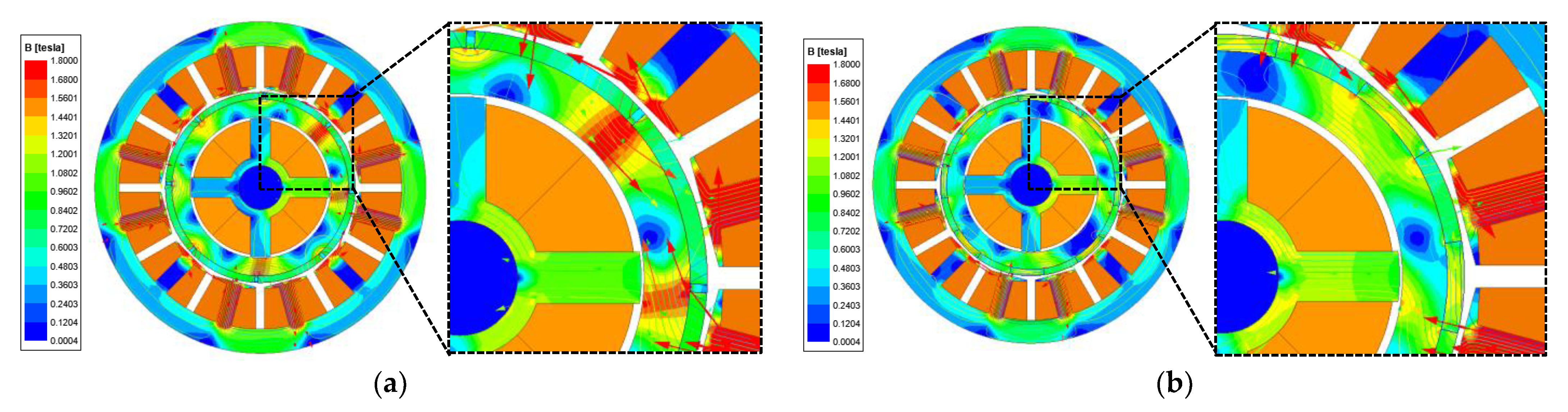
In Figure 4, the bearing force waveform by the magnetomotive force of the bearing, magnet, and stator has a low value at 248° electric and maximum value at 178° electric. Therefore, to determine the corresponding causes, the magnetic flux density and flux lines for each rotation angle should be analyzed. Figure 5 shows the flux lines based on the magnetomotive force at a rotation angle of 248° electric. The flux lines for each magnetomotive force are combined or offset to create the flux line shown in Figure 5e. The flux line based on the magnetomotive force at a rotation angle of 178° electric is shown in Figure 6. Similarly, the flux lines for each magnetomotive force are also combined or offset to create the flux line shown in Figure 6e.
The magnetic flux density plots in Figure 5e and Figure 6e are represented in Figure 7a,b, respectively. In Figure 7, the partial magnetic saturation of the rotor back yoke is lower at a rotation angle of 178° electric compared to that at a rotation angle of 248° electric. The magnetic saturation of the shaft results in reluctance in the magnetic circuit of a magnetic bearing. The magnetic circuit for the magnetomotive force of the magnetic bearing is illustrated in Figure 5d and Figure 6d. Therefore, the bearing force increased at a rotational angle of 178° electric, where the magnetic saturation of the shaft was low compared to that with the rotational angle of 248° electric.
In conclusion, the magnetomotive forces of the stator, PM, and magnetic bearing were combined in the rotor back yoke to create partial magnetic saturation. In addition, the magnetic saturation of the shaft also changed because the flux line due to the magnetomotive force of the stator and magnet changed depending on the rotor position. Therefore, as shown in Figure 4, the bearing force appears as a waveform with ripples, depending on the position of the rotor.
3. Methodology to Reduce Bearing Force Ripple and Torque Ripple
The rotor parameters for reducing the bearing force and torque ripples are shown in Figure 8. As mentioned in Section 3, reducing the magnetic saturation of the rotor back yoke is essential in the design of an integrated magnetic bearing motor. The magnetic saturation of the rotor back yoke considerably affects the torque and bearing force. Therefore, a design that reduces magnetic saturation is necessary for the performance of both the magnetic bearing and motor itself. The Halbach array can reduce the magnetic saturation of the rotor back yoke, and variables that can increase its effect on the Halbach array must be selected, such as the angle of the tangential PM.
As the angle of the tangential PM increases, the amount of radial PM used inevitably decreases. When the amount of tangential PM increases, the magnetic saturation of the rotor back yoke can be removed, but the size of the air-gap flux density decreases. As the air-gap flux density decreases, the torque and output of the motor decrease. This can be compensated by varying the thickness of the PM.
Two variables taper the PM: radial and tangential PM tapering. The tapering parameter for the PM represents the distance from the center of the coordinate system, which causes the PM to move to the center of the rotor. Therefore, as the variable value increases, the size of the tapering applied to the PM increases. In addition, the tapering of PMs can reduce the cogging torque and torque ripple by reducing the change in the reluctance of the air gap. Because the effect of the PM on the air-gap side is reduced, the magnetic saturation of the rotor back yoke is reduced, as well as the bearing force.
Figure 9 shows a flow chart for the design of the integrated magnetic-bearing motor. Through FEA, the rotor parameters are selected by targeting the maximum bearing force and torque and the minimum bearing force ripple and torque ripple.
4. Specifications and Target Function of Basic Model
The two-dimensional (2D) shape of the basic model is shown in Figure 10. The design model was selected as a motor for a 5-kW vacuum pump used in the semiconductor CVD process. The pole slots of the design model were 8 poles and 12 slots, and concentrated windings were used. The rated speed was 6000 rpm and the direct current link voltage was 311 V peak, designed considering a control margin of 10%. The basic specifications of the motor parts in the design model are listed in Table 1. The specifications of the magnetic bearing inside the rotor of the design model are listed in Table 2.
The four design target functions, torque, torque ripple, bearing force, and bearing force ripple, are presented in Table 3. The target values were: 8 N∙m or more for the torque, 8% or less for the torque ripple, 70 N or more for the bearing force, and 3% or less for the bearing force ripple. The target specification for the bearing force was calculated by multiplying the rotor weight of approximately 1.42 kg, gravitational acceleration of 9.8 m/s2, and a safety factor of 5.
5. Selection of Design Variables and Proposed Model
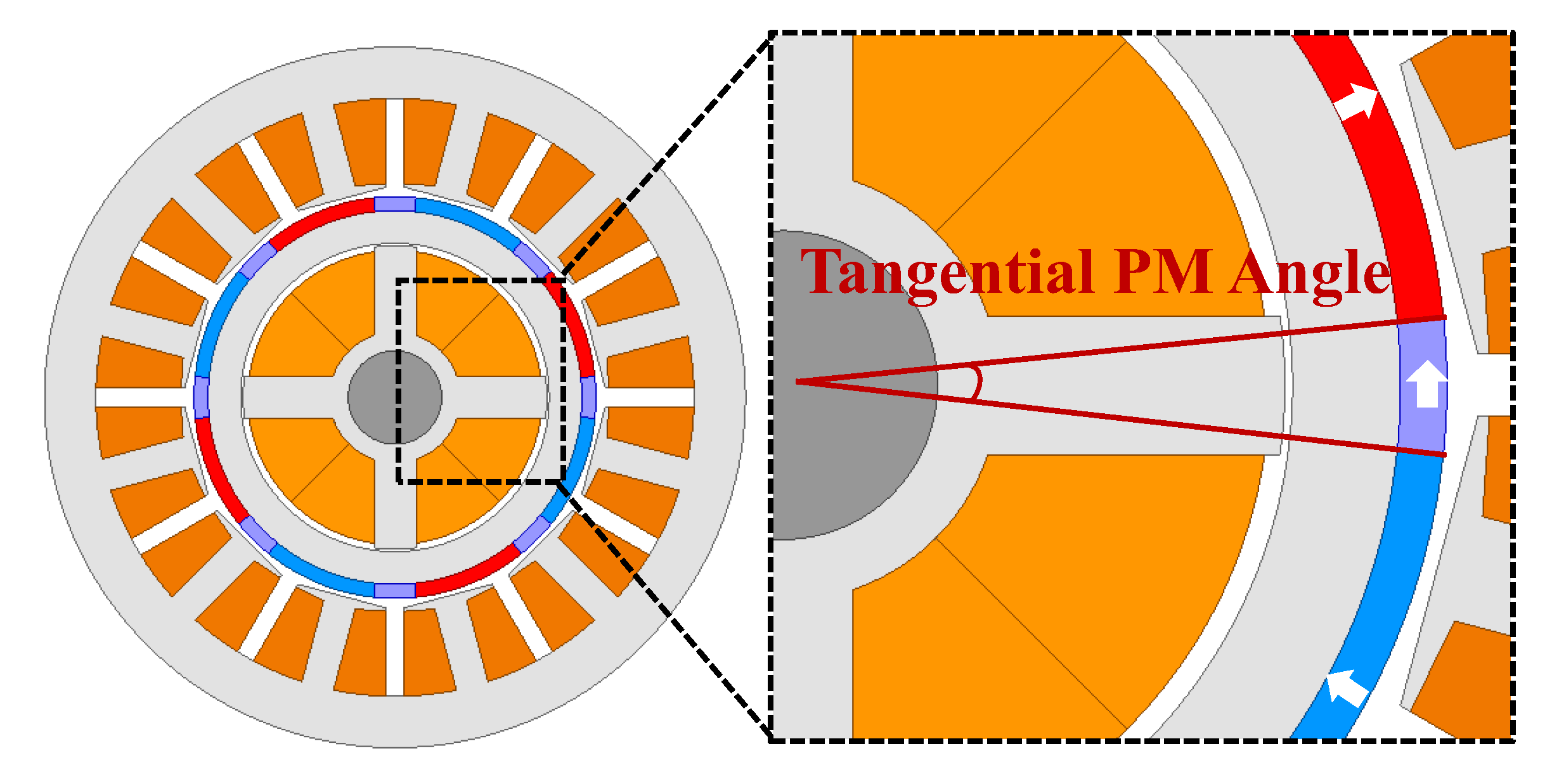
Figure 11 shows the rotor parameters for the tangential PM angle. The torque and torque ripples for the tangential PM angle are shown in Figure 12. The torque value tended to decrease linearly as the tangential PM angle increased. Moreover, the torque ripple did not change linearly with respect to the tangential PM angle, and the torque ripple reached a minimum at 22° mechanical. The bearing force and bearing force ripple based on the angle of the tangential PM are shown in Figure 13. The magnitude of the bearing force increased linearly as the angle of the tangential PM increased, but the value did not considerably change beyond 16° mechanical. The bearing force ripple was considerably affected by the angle of the tangential PM. As the angle increased, the bearing force ripple decreased and exhibited similar value for angles above 22° mechanical. Figure 14 shows the causes of the analysis results for the rotor variables, where the rotor magnetic flux density is considerably smaller when the rotor variable value is 22° mechanical than when it is 2° mechanical.
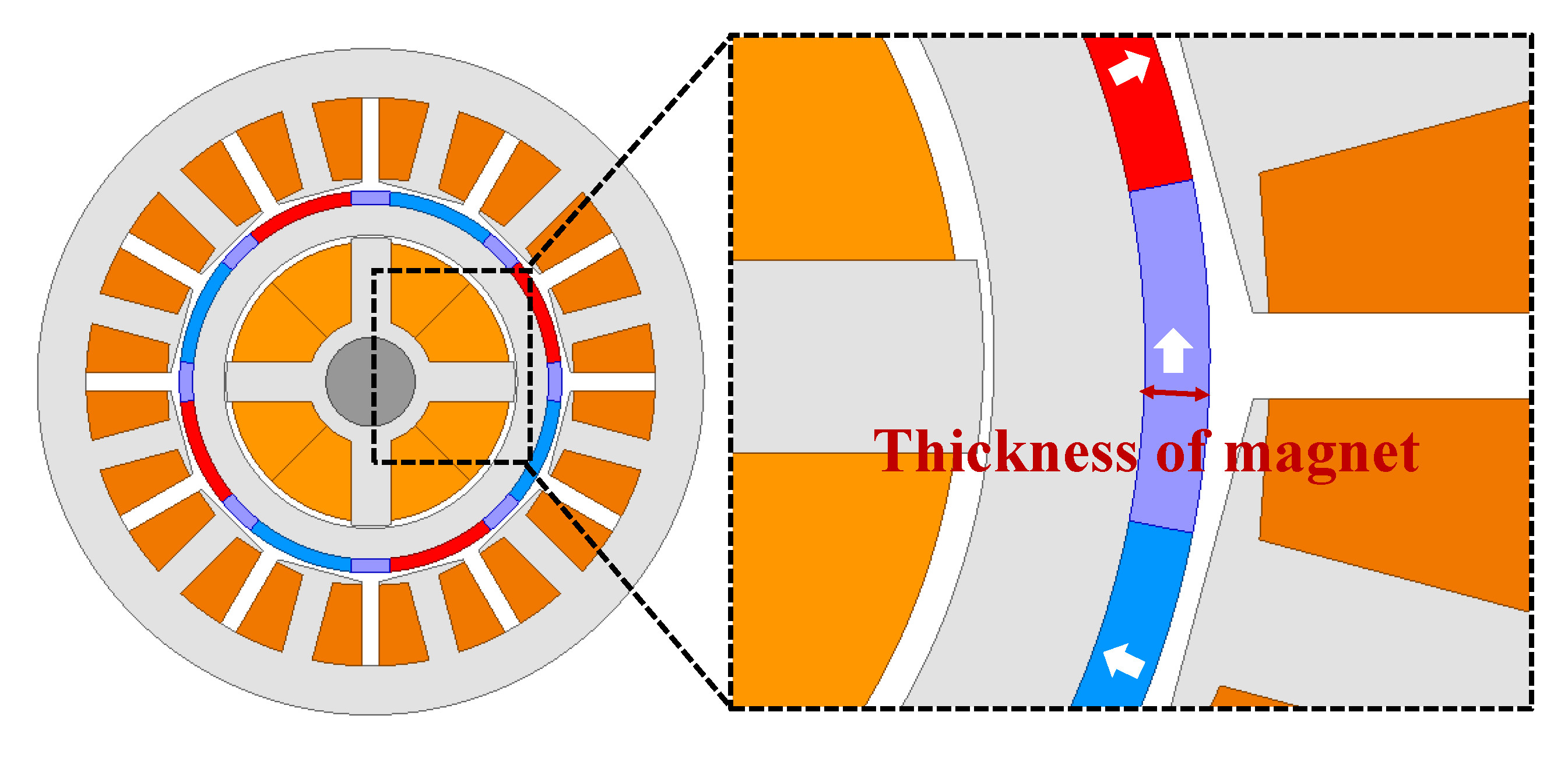
In Figure 15, the rotor parameters for the magnet thickness are shown. The torque and torque ripples with respect to the tangential PM angle are shown in Figure 16. As the thickness of the PM increases, the magnetic flux of the PM increases; thus, the torque increases linearly. The torque ripple continued to increase as the thickness of the PM increased. The bearing force and bearing force ripple according to the PM thickness are shown in Figure 17. The magnitude of the bearing force decreased linearly as the thickness of the PM increased. This is because the number of coils and magnetomotive force of the magnetic bearing decreased as the thickness of the PM increased. The bearing force ripple continued to increase as the thickness of the PM increased. From the results of Figure 16 and Figure 17, the optimum value for the thickness of the PM is 3 mm; however, the rotor variable was selected as 3.5 mm. In Table 3, the target torque is 8 N∙m, and the design was performed considering the torque margin.
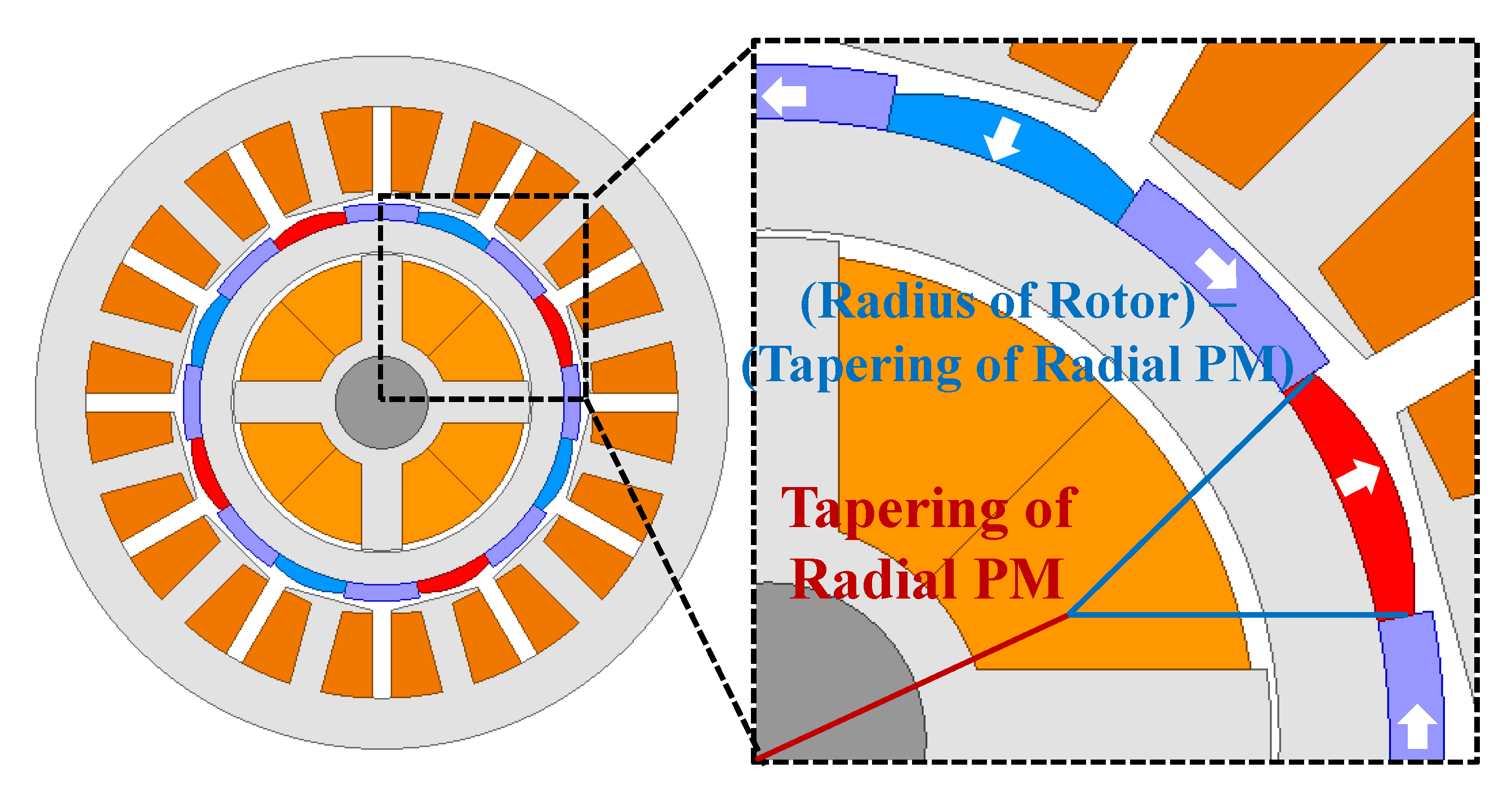
Figure 18 shows the rotor parameters for tapering the radial PM. The torque and torque ripple for tapering the radial PM are shown in Figure 19. The value of the torque decreased as the value of the tapering of the radial PM increased. This is because as the value of tapering increased, the amount of PM used decreased, and the size of the air gap magnetic flux density decreased. The torque ripple continued to decrease until the value of the rotor variable was 15 mm, and increased again at values above 15 mm. The bearing force and bearing force ripple for tapering of the radial PM are shown in Figure 20. As observed, the magnitude of the bearing force was almost constant as the value of the rotor variable increased. The bearing force ripple continued to decrease according to the rotor parameter value. This is because the magnetic saturation of the rotor back yoke was reduced owing to the reduction of the number of radial PMs. Therefore, a rotor variable of 15 mm was selected, which can reduce the size of the torque ripple and ripple of the radial force.
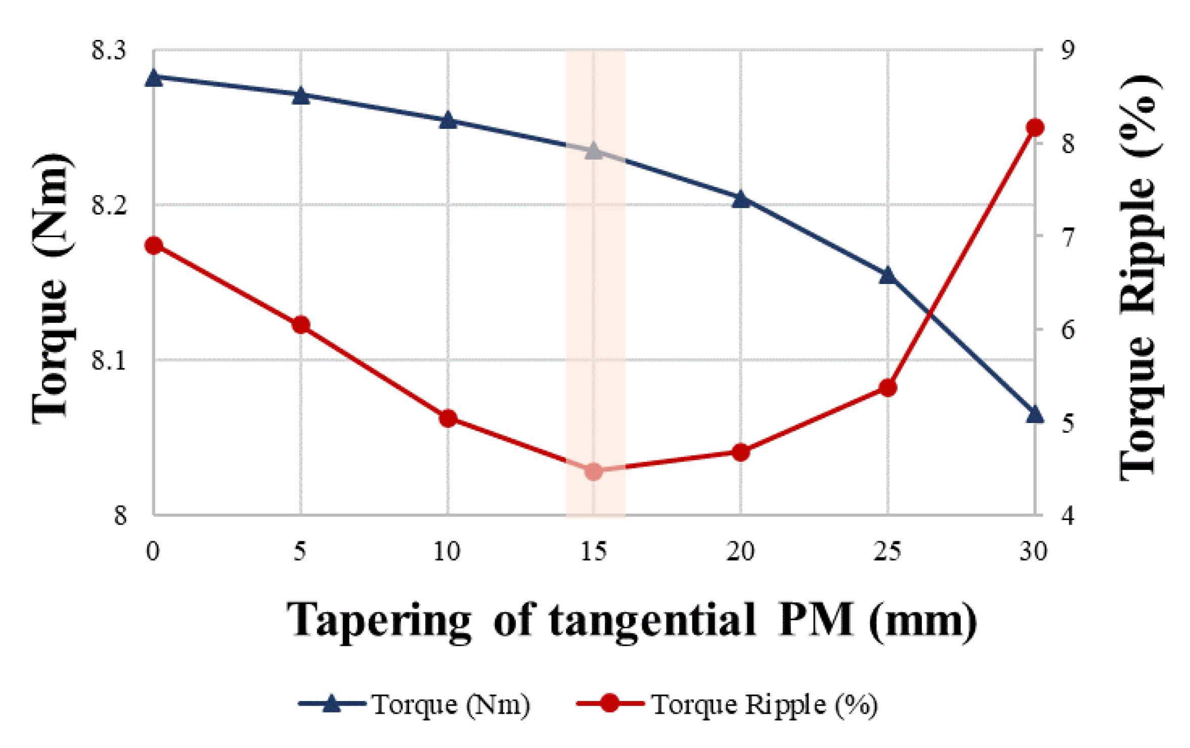
Figure 21 shows the rotor parameters for tapering the tangential PM. The torque and torque ripple for the tangential PM tapering are shown in Figure 22. The results for torque and torque ripple are the same as the tendencies of the results according to the tapering of the radial PM discussed earlier. The value of the torque decreased as the value of the tapering of the tangential PM increased. The torque ripple continued to decrease until the rotor variable value was 15 mm and increased again at a variable value of 15 mm or more. The results for the bearing force are also the same as the tendency of results according to the tapering of the radial PM discussed earlier. The bearing force and bearing force ripple for tapering of the tangential PM are shown in Figure 23. As observed, the magnitude of the bearing force was almost constant as the value of the rotor variable increased. The bearing force ripple continued to decrease according to the rotor parameter value. Therefore, a rotor variable of 15 mm was selected, which can reduce the size of the torque ripple and ripple of the radial force.
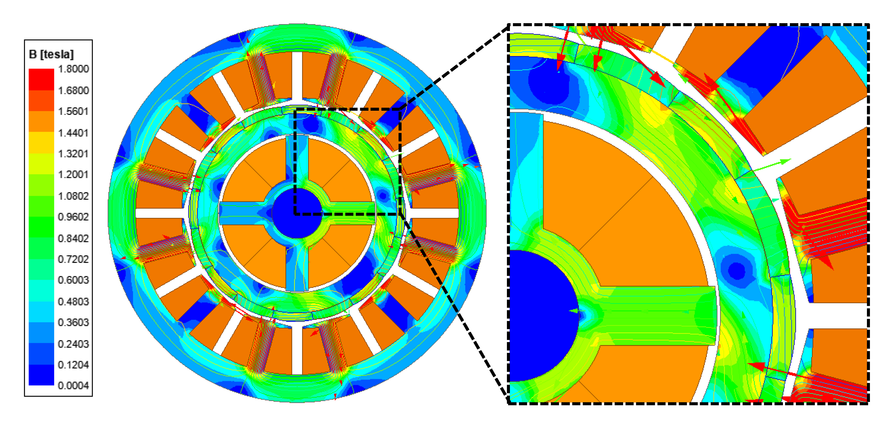
Finally, the proposed model was derived using the rotor design described above. The 2D cross sections of the basic and proposed models of the integrated magnetic-bearing motor are shown in Figure 24, and the corresponding parameters are listed in Table 4. In addition, the magnetic flux density plots of the basic and proposed models are shown in Figure 25 and Figure 26, where the maximum values of the rotor flux density were approximately 1.68 T and 1.44 T, respectively. In the case of the proposed model, because the angle to the tangential PM was 22° mechanical, considerably larger than the 12° mechanical angle of the basic model, the performance of the Halbach array was improved. Therefore, the proposed model is advantageous in terms of magnetic saturation of the rotor back yoke, increases in the size of the bearing force, and performance considering the ripple.
The torque waveforms of the basic and proposed models at a rotational speed of 6000 rpm are shown in Figure 27. The waveforms for the bearing force of the two models under the same conditions are shown in Figure 28. The resulting values for the waveforms in Figure 27 and Figure 28 are listed in Table 5. Compared to the basic model, the torque decreased by approximately 0.61 N∙m in the proposed model, whereas the torque ripple considerably decreased by approximately 38.11%. In addition, the sizes of the bearing force and bearing force ripple of the proposed model were reduced by 4.1 N and 11.79%, respectively, compared with those in the basic model. Compared with the basic model, the proposed model was advantageous in terms of torque ripple and bearing force ripple, and all target values of the objective function were satisfied.
6. Conclusions
In this study, a method to reduce the bearing force and torque ripples of an integrated magnetic bearing motor through parameters for a Halbach array and PM tapering was proposed. First, the causes of the bearing force ripple in the integrated magnetic bearing motors were analyzed in detail. The bearing force ripple was caused by the magnetic saturation of the rotor-back yoke. This magnetic saturation occurred when the magnetic fluxes of the rotor, stator, and magnetic bearing were combined at the back yoke of the rotor. The magnetic saturation of the rotor-back yoke could be effectively removed using a Halbach array. The bearing force and torque were analyzed using the variables for the Halbach array and for the tapering of the PM. The average bearing force and torque were maximized, and the ripple was minimized through the rotor parameters. Based on the design of an integrated magnetic bearing motor, this size increase can be minimized by using a magnetic bearing. Through an integrated magnetic bearing motor structure, magnetic bearings are expected to be used in a wide range of fields. In the future, research will be conducted on equalizing the integrated magnetic bearing motor with a magnetic circuit and predicting the force.
Author Contributions
Conceptualization, I.-J.Y. and D.-H.J.; methodology, I.-J.Y.; software, I.-J.Y. and M.-K.H.; validation, I.-J.Y. and M.-K.H.; formal analysis, I.-J.Y.; investigation, I.-J.Y.; resources, I.-J.Y.; data curation, I.-J.Y.; writing—original draft preparation, I.-J.Y.; writing—review and editing, J.L., W.-H.K. and D.-H.J.; visualization, I.-J.Y. and M.-K.H.; supervision, J.L., W.-H.K., and D.-H.J.; project administration, J.L., W.-H.K., and D.-H.J. All authors have read and agreed to the published version of the manuscript.
Funding
This work was supported by a National Research Foundation of Korea (NRF) grant funded by the Korean government (MSIT) (No. 2020R1F1A1075209) and in part by a NRF grant funded by the Korean government (MSIT) (No. 2020R1A2C1013724).
Data Availability Statement
Not applicable.
Conflicts of Interest
The authors declare no conflict of interest.
References
- Zhang, Z.; Yu, S.; Zhang, F.; Jin, S.; Wang, X. Electromagnetic and Structural Design of a Novel Low-Speed High-Torque Motor with Dual-Stator and PM-Reluctance Rotor. IEEE Trans. Appl. Supercond. 2020, 30, 1–5. [Google Scholar] [CrossRef]
- Dong, B.; Wang, K.; Han, B.; Zheng, S. Thermal Analysis and Experimental Validation of a 30 kW 60000 r/min High-Speed Permanent Magnet Motor with Magnetic Bearings. IEEE Access 2019, 7, 92184–92192. [Google Scholar] [CrossRef]
- Kim, J.-H.; Kim, D.-M.; Jung, Y.-H.; Lim, M.-S. Design of Ultra-High-Speed Motor for FCEV Air Compressor Considering Mechanical Properties of Rotor Materials. IEEE Trans. Energy Convers. 2021, 36, 2850–2860. [Google Scholar] [CrossRef]
- Islam, M.K.; Tasnim, K.N.; Choi, S.; Kwak, S.; Arafat, A. Designing High-Power Ultra-High-Speed Motor Using a New Multiphysics Multi-Objective Optimization Method for Mechanical Antenna Applications. IEEE Access 2022, 10, 106305–106323. [Google Scholar] [CrossRef]
- Lim, M.-S.; Kim, J.-M.; Hwang, Y.-S.; Hong, J.-P. Design of an Ultra-High-Speed Permanent-Magnet Motor for an Electric Turbocharger Considering Speed Response Characteristics. IEEE/ASME Trans. Mechatron. 2017, 22, 774–784. [Google Scholar] [CrossRef]
- Jang, G.-H.; Ahn, J.-H.; Kim, B.-O.; Lee, D.-H.; Bang, J.-S.; Choi, J.-Y. Design and Characteristic Analysis of a High-Speed Permanent Magnet Synchronous Motor Considering the Mechanical Structure for High-Speed and High-Head Centrifugal Pumps. IEEE Trans. Magn. 2018, 54, 1–6. [Google Scholar] [CrossRef]
- Jiwei, C.; Zhengnan, H.; Yuchen, S.; Liyi, L. Design and Test of a High-Speed Double-Winding High Temperature Superconducting Synchronous Motor. IEEE Access 2020, 8, 77470–77481. [Google Scholar] [CrossRef]
- Smirnov, A.; Uzhegov, N.; Sillanpää, T.; Pyrhönen, J.; Pyrhönen, O. High-Speed Electrical Machine with Active Magnetic Bearing System Optimization. IEEE Trans. Ind. Electron. 2017, 64, 9876–9885. [Google Scholar] [CrossRef] [Green Version]
- Looser, A.; Kolar, J.W. An Active Magnetic Damper Concept for Stabilization of Gas Bearings in High-Speed Permanent-Magnet Machines. IEEE Trans. Ind. Electron. 2014, 61, 3089–3098. [Google Scholar] [CrossRef]
- Hirose, K.; Komori, M.; Asami, K.; Sakai, N. Application of One-Axis-Controlled Magnetic Bearing with a Hollow Shaft to Noncontact Rotation Drive. IEEE Trans. Magn. 2015, 51, 1–4. [Google Scholar] [CrossRef]
- Uzhegov, N.; Smirnov, A.; Park, C.H.; Ahn, J.H.; Heikkinen, J.; Pyrhönen, J. Design Aspects of High-Speed Electrical Machines With Active Magnetic Bearings for Compressor Applications. IEEE Trans. Ind. Electron. 2017, 64, 8427–8436. [Google Scholar] [CrossRef]
- Bangcheng, H.; Shiqiang, Z.; Xi, W.; Qian, Y. Integral Design and Analysis of Passive Magnetic Bearing and Active Radial Magnetic Bearing for Agile Satellite Application. IEEE Trans. Magn. 2012, 48, 1959–1966. [Google Scholar] [CrossRef]
- Huang, Z.; Fang, J.; Liu, X.; Han, B. Loss Calculation and Thermal Analysis of Rotors Supported by Active Magnetic Bearings for High-Speed Permanent-Magnet Electrical Machines. IEEE Trans. Ind. Electron. 2016, 63, 2027–2035. [Google Scholar] [CrossRef]
- Zheng, S.; Han, B.; Feng, R.; Jiang, Y. Vibration Suppression Control for AMB-supported motor driveline system using synchronous rotating frame transformation. IEEE Trans. Ind. Electron. 2015, 62, 5700–5708. [Google Scholar] [CrossRef]
- Sun, J.; Ju, Z.; Peng, C.; Le, Y.; Ren, H. A Novel 4-DOF Hybrid Magnetic Bearing for DGMSCMG. IEEE Trans. Ind. Electron. 2017, 64, 2196–2204. [Google Scholar] [CrossRef]
- Le, Y.; Sun, J.; Han, B. Modeling and Design of 3-DOF Magnetic Bearing for High-Speed Motor Including Eddy-Current Effects and Leakage Effects. IEEE Trans. Ind. Electron. 2016, 63, 3656–3665. [Google Scholar] [CrossRef]
- Han, B.; Xu, Q.; Yuan, Q. Multiobjective Optimization of a Combined Radial-Axial Magnetic Bearing for Magnetically Suspended Compressor. IEEE Trans. Ind. Electron. 2016, 63, 2284–2293. [Google Scholar]
- Ye, X.; Le, Q.; Zhou, Z. A Novel Homopolar Four Degrees of Freedom Hybrid Magnetic Bearing. IEEE Trans. Magn. 2020, 56, 1–4. [Google Scholar] [CrossRef]
- Jiang, H.; Su, Z.; Wang, D. Analytical Calculation of Active Magnetic Bearing Based on Distributed Magnetic Circuit Method. IEEE Trans. Energy Convers. 2021, 36, 1841–1851. [Google Scholar] [CrossRef]
- Wang, H.; Liu, K.; Wei, J.; Hu, H. Analytical Modeling of Air Gap Magnetic Fields and Bearing Force of a Novel Hybrid Magnetic Thrust Bearing. IEEE Trans. Magn. 2021, 10, 1–7. [Google Scholar] [CrossRef]
- Ren, X.; Feng, M.; Chen, S. Design Method Based on Asymmetry Factor of a Novel Three-Pole Magnetic Bearing. IEEE Trans. Appl. Supercond. 2021, 31, 1–4. [Google Scholar] [CrossRef]
- Zhang, T.; Ye, X.; Mo, L.; Liu, X. Modeling and Performance Analysis on the Slice Hybrid Magnetic Bearing with Two Radial Air-Gaps. IEEE Trans. Appl. Supercond. 2019, 29, 1–5. [Google Scholar] [CrossRef]
- Zhang, T. Modeling and Performance Analysis on the Five Degrees of Freedom Slice Hybrid Magnetic Bearing. IEEE Trans. Appl. Supercond. 2019, 29, 1–5. [Google Scholar] [CrossRef]
- Zhang, W.; Yang, H.; Cheng, L.; Zhu, H. Modeling Based on Exact Segmentation of Magnetic Field for a Centripetal Force Type-Magnetic Bearing. IEEE Trans. Ind. Electron. 2020, 67, 7691–7701. [Google Scholar] [CrossRef]
- Jiang, D.; Li, T.; Ji, Z.; Sun, H. Novel Topologies of Power Electronics Converter as Active Magnetic Bearing Drive. IEEE Trans. Ind. Electron. 2020, 67, 950–959. [Google Scholar] [CrossRef]
- Wang, Z.; Zhang, T.; Wu, S. Suspension Force Analysis of Four-Pole Hybrid Magnetic Bearing with Large Radial Bearing Capacity. IEEE Trans. Magn. 2020, 56, 1–4. [Google Scholar] [CrossRef]
- Zhang, T.; Ye, X.; Mo, L.; Lu, Q. Electromagnetic performance analysis on the bearingless permanent magnet synchronous motor with Halbach magnetized rotor. IEEE Access 2019, 7, 121265–121274. [Google Scholar] [CrossRef]
- Liu, K.; Yin, M.; Hua, W.; Ma, Z.; Lin, M.; Kong, Y. Design and analysis of Halbach ironless flywheel BLDC motor/generators. IEEE Trans. Magn. 2018, 54, 1–5. [Google Scholar] [CrossRef]
- Jun, H.-W.; Seol, H.-S.; Lee, J. Design of high power density TVC driving motor for space launch vehicle using Halbach Magnet Array Structure. IEEE Trans. Appl. Supercond. 2018, 28, 1–5. [Google Scholar] [CrossRef]
Figure 1.
Halbach array principle.

Figure 2.
Structure of integrated magnetic bearing motor.

Figure 3.
Principle of magnetic bearing.

Figure 4.
Bearing force waveform according to magnetomotive force.

Figure 5.
Flux line according to magnetomotive force at rotation angle 248° electric: (a) Magnet; (b) stator; (c) magnet, stator; (d) bearings; (e) bearings, magnets, and stators.
Figure 5.
Flux line according to magnetomotive force at rotation angle 248° electric: (a) Magnet; (b) stator; (c) magnet, stator; (d) bearings; (e) bearings, magnets, and stators.

Figure 6.
Flux line according to magnetomotive force at rotation angle 178° electric: (a) Magnet; (b) stator; (c) magnet, stator; (d) bearings; (e) bearings, magnets, and stators.
Figure 6.
Flux line according to magnetomotive force at rotation angle 178° electric: (a) Magnet; (b) stator; (c) magnet, stator; (d) bearings; (e) bearings, magnets, and stators.

Figure 7.
Magnetic saturation plot of shaft according to rotating angle of rotor: Rotating angle: (a) 248° electric; (b) 178° electric.
Figure 7.
Magnetic saturation plot of shaft according to rotating angle of rotor: Rotating angle: (a) 248° electric; (b) 178° electric.

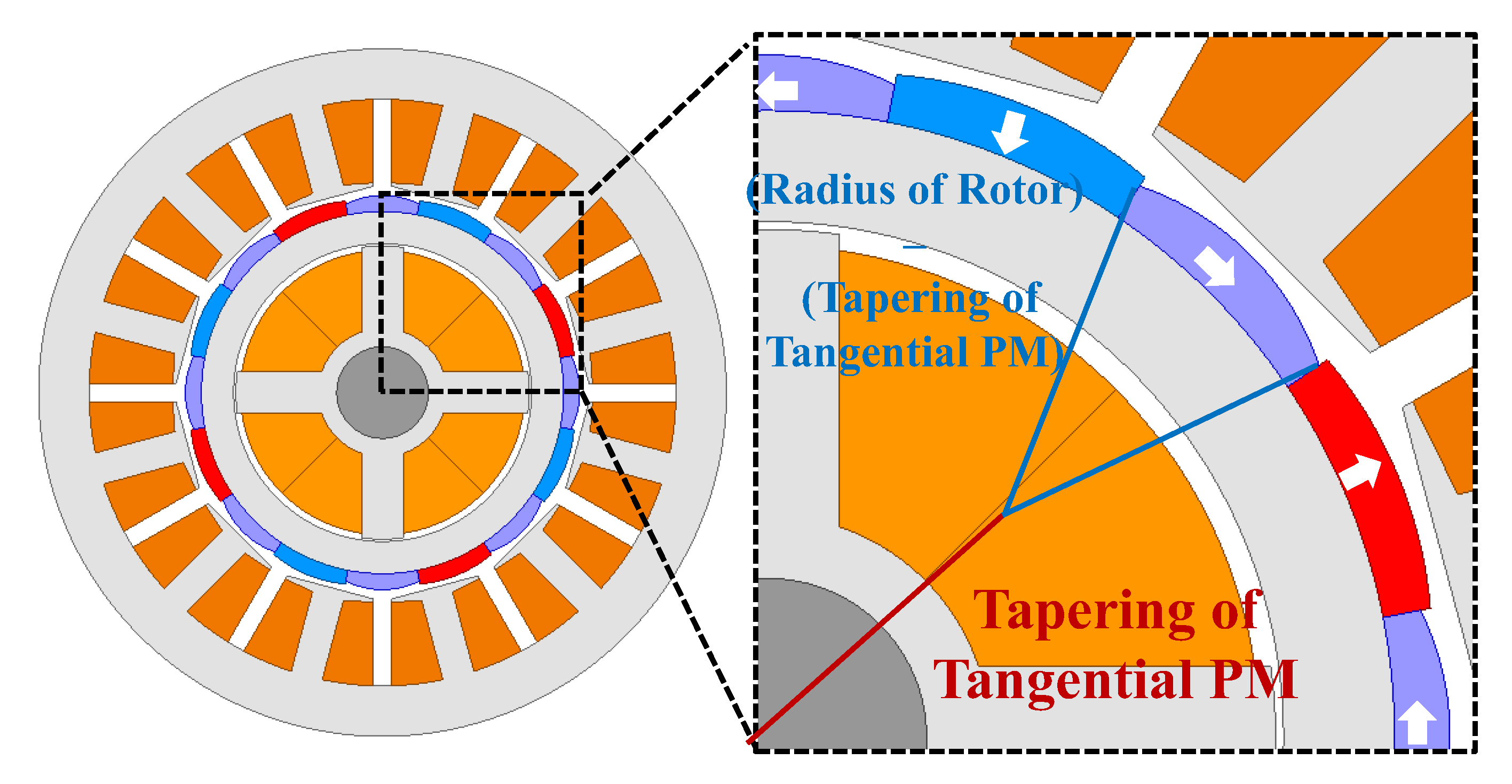
Figure 8.
Geometric parameters of integrated magnetic bearing motor.

Figure 9.
Flow chart for designing an integrated magnetic bearing motor.

Figure 10.
2D cross section of basic model.

Figure 11.
Rotor variable for tangential PM angle.

Figure 12.
Torque and ripple according to tangential PM angle.

Figure 13.
Bearing force and ripple according to tangential PM angle.

Figure 14.
Rotor magnetic flux density plot: Tangential PM angle: (a) 2° mechanical; (b) 22° mechanical.
Figure 14.
Rotor magnetic flux density plot: Tangential PM angle: (a) 2° mechanical; (b) 22° mechanical.

Figure 15.
Rotor variable for the thickness of the magnet.

Figure 16.
Torque and ripple according to the thickness of the magnet.

Figure 17.
Bearing force and ripple according to the thickness of the magnet.

Figure 18.
Rotor variable for tapering of radial PM.

Figure 19.
Torque and ripple according to tapering of radial PM.

Figure 20.
Bearing force and ripple according to tapering of radial PM.

Figure 21.
Rotor variable for tapering of tangential PM.

Figure 22.
Torque and ripple according to tapering of tangential PM.

Figure 23.
Bearing force and ripple according to tapering of tangential PM.

Figure 24.
2D cross section of integrated magnetic bearing: (a) Basic model; (b) proposed model.

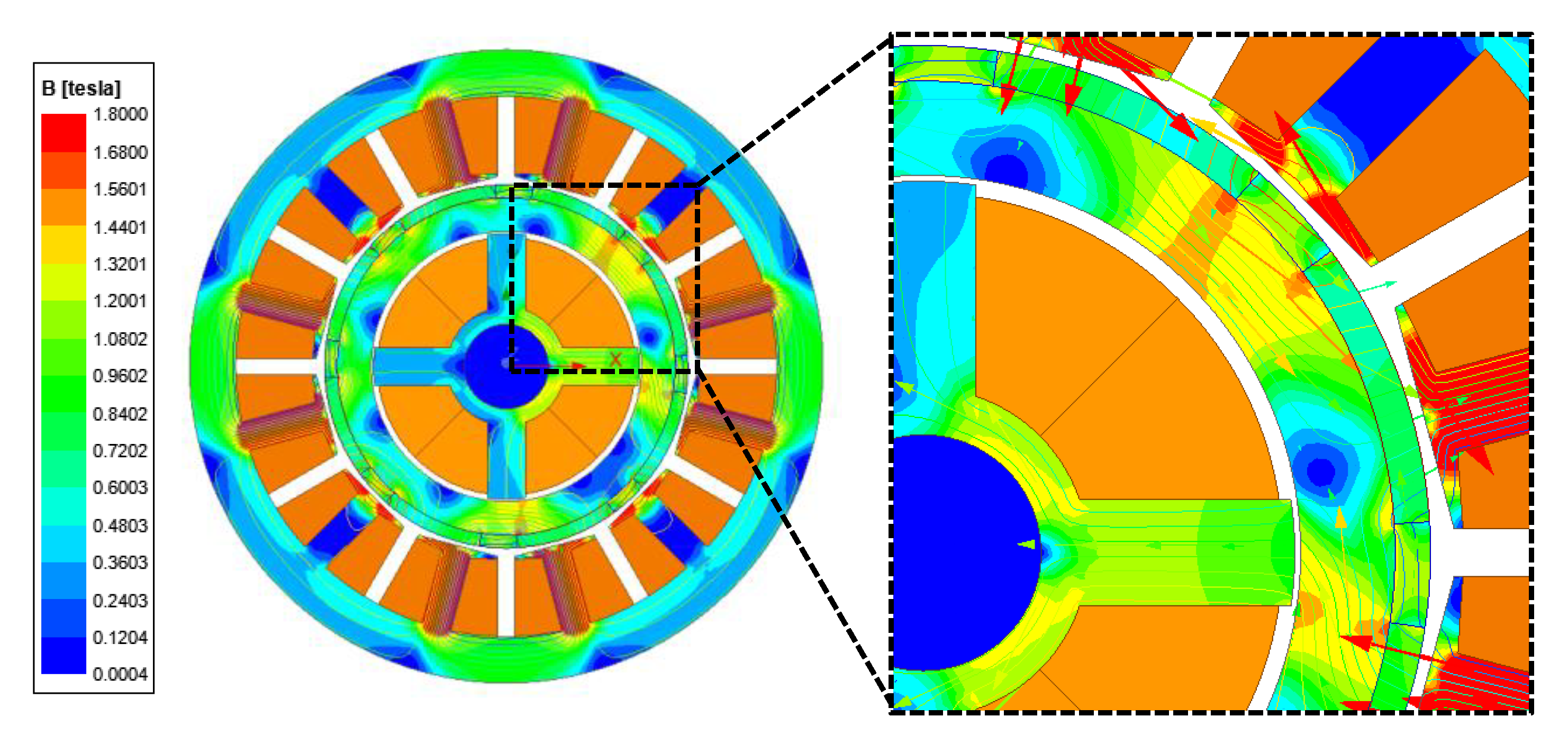
Figure 25.
Rotor flux density plot of basic model.

Figure 26.
Rotor flux density plot of proposed model.

Figure 27.
Torque waveform of basic and proposed models.

Figure 28.
Bearing force waveform of basic and proposed models.


Table 1.
Specifications for the integrated magnetic bearing motor.
| Parameter | Value | Unit |
|---|---|---|
| Pole/slot | 8/12 | – |
| Length of airgap | 1 | mm |
| Power | 5 | kW |
| Speed | 6000 | rpm |
| Current | 17 | Arms |
| Voltage | 311 | Vpeak |
| Outer/inner diameter of stator | 150/88 | mm |
| Outer/inner diameter of rotor | 86/62 | mm |
| Material of core | 35PN230 | – |
| Length of stacking | 57.2 | mm |
| Number of turns | 77 | – |
| Number of parallel branches | 4 | – |
| Diameter of coil | 1 | mm |
| Depth of magnet | 4 | mm |
| Material of magnet | N42UH | - |
Table 2.
Specifications for the magnetic bearing in an integrated magnetic bearing motor.
| Parameter | Value | Unit |
|---|---|---|
| Pole | 4 | – |
| Length of airgap | 0.5 | mm |
| Current | 5 | Apeak |
| Outer/inner diameter of core | 61/20 | mm |
| Length of stacking | 57.2 | mm |
| Material of core | 35PN230 | – |
| Number of turns | 92 | – |
| Diameter of coil | 1 | mm |
Table 3.
Objective function of design.
| Parameter | Value | Unit |
|---|---|---|
| Torque | 8 | N·m |
| Torque ripple | 8 | % |
| Bearing force | 70 | Newton |
| Bearing force ripple | 3 | % |
Table 4.
Rotor parameters of basic and proposed models.
| Parameter | Basic Model | Proposed Model | Unit |
|---|---|---|---|
| Tangential PM angle | 12 | 22 | ° mechanical |
| Thickness of magnet | 3 | 3.5 | mm |
| Tapering of radial PM | 0 | 15 | mm |
| Tapering oftangential PM | 0 | 15 | mm |
Table 5.
Values for the target function of basic and proposed models.
| Parameter | Target Value | Basic Model | Proposed Model | Unit |
|---|---|---|---|---|
| Torque | 8 | 8.85 | 8.24 | N∙m |
| Torque ripple | 8 | 42.58 | 4.47 | % |
| Bearing force | 70 | 154.11 | 150.01 | N |
| Bearing force ripple | 3 | 14.77 | 2.98 | % |
Disclaimer/Publisher’s Note: The statements, opinions and data contained in all publications are solely those of the individual author(s) and contributor(s) and not of MDPI and/or the editor(s). MDPI and/or the editor(s) disclaim responsibility for any injury to people or property resulting from any ideas, methods, instructions or products referred to in the content. |
© 2023 by the authors. Licensee MDPI, Basel, Switzerland. This article is an open access article distributed under the terms and conditions of the Creative Commons Attribution (CC BY) license (https://creativecommons.org/licenses/by/4.0/).
Share and Cite
MDPI and ACS Style
Yang, I.-J.; Hong, M.-K.; Lee, J.; Kim, W.-H.; Jung, D.-H. Design for Reducing Bearing Force Ripple and Torque Ripple of Integrated Magnetic Bearing Motor through Halbach Array. Energies 2023, 16, 1249. https://doi.org/10.3390/en16031249
AMA Style
Yang I-J, Hong M-K, Lee J, Kim W-H, Jung D-H. Design for Reducing Bearing Force Ripple and Torque Ripple of Integrated Magnetic Bearing Motor through Halbach Array. Energies. 2023; 16(3):1249. https://doi.org/10.3390/en16031249
Chicago/Turabian StyleYang, In-Jun, Min-Ki Hong, Ju Lee, Won-Ho Kim, and Dong-Hoon Jung. 2023. "Design for Reducing Bearing Force Ripple and Torque Ripple of Integrated Magnetic Bearing Motor through Halbach Array" Energies 16, no. 3: 1249. https://doi.org/10.3390/en16031249
Note that from the first issue of 2016, this journal uses article numbers instead of page numbers. See further details here.