
An Alternative to Conventional Rock Fragmentation Methods Using SCDA: A Review


Abstract
:1. Introduction
1.1. Explosive Blasting
1.2. Hydraulic Fracturing
1.3. Electrical Disintegration
2. Is There a More Effective Method for Rock Fragmentation?
2.1. Commercially Available SCDA
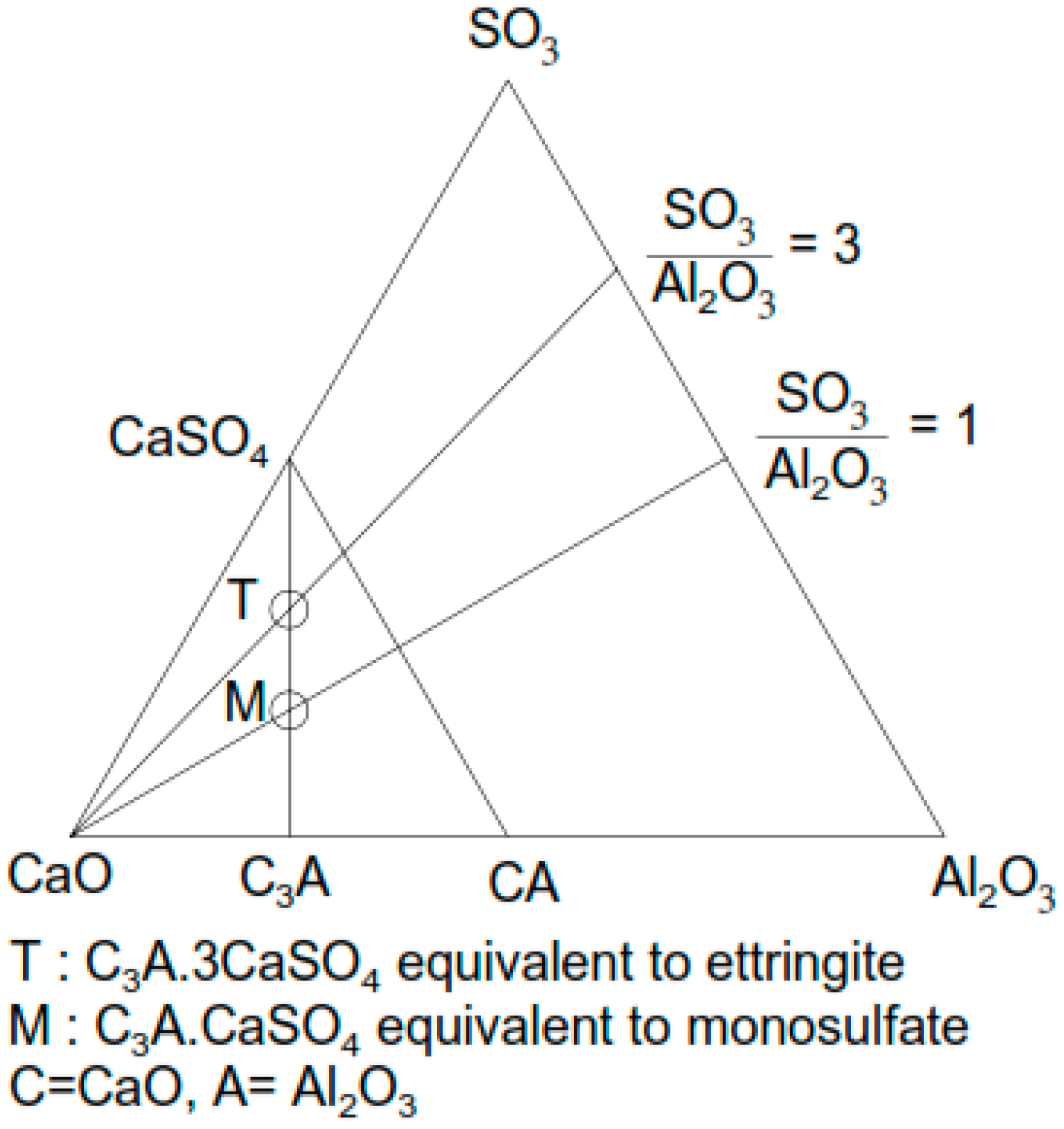
2.2. Chemical Composition of SCDA
- Type K: Anhydrous calcium sulfoaluminate (4CaO·3Al2O3·SO3), calcium sulfate (CaSO4), and calcium oxide (CaO);
- Type M: Calcium aluminate (CaO·Al2O3) and CaSO4;
- Type S: Tricalcium aluminate (CaO·Al2O3) and CaSO4.
2.3. Quantification of Expansive Pressure Generation
3. Factors Influencing the Performance of SCDA
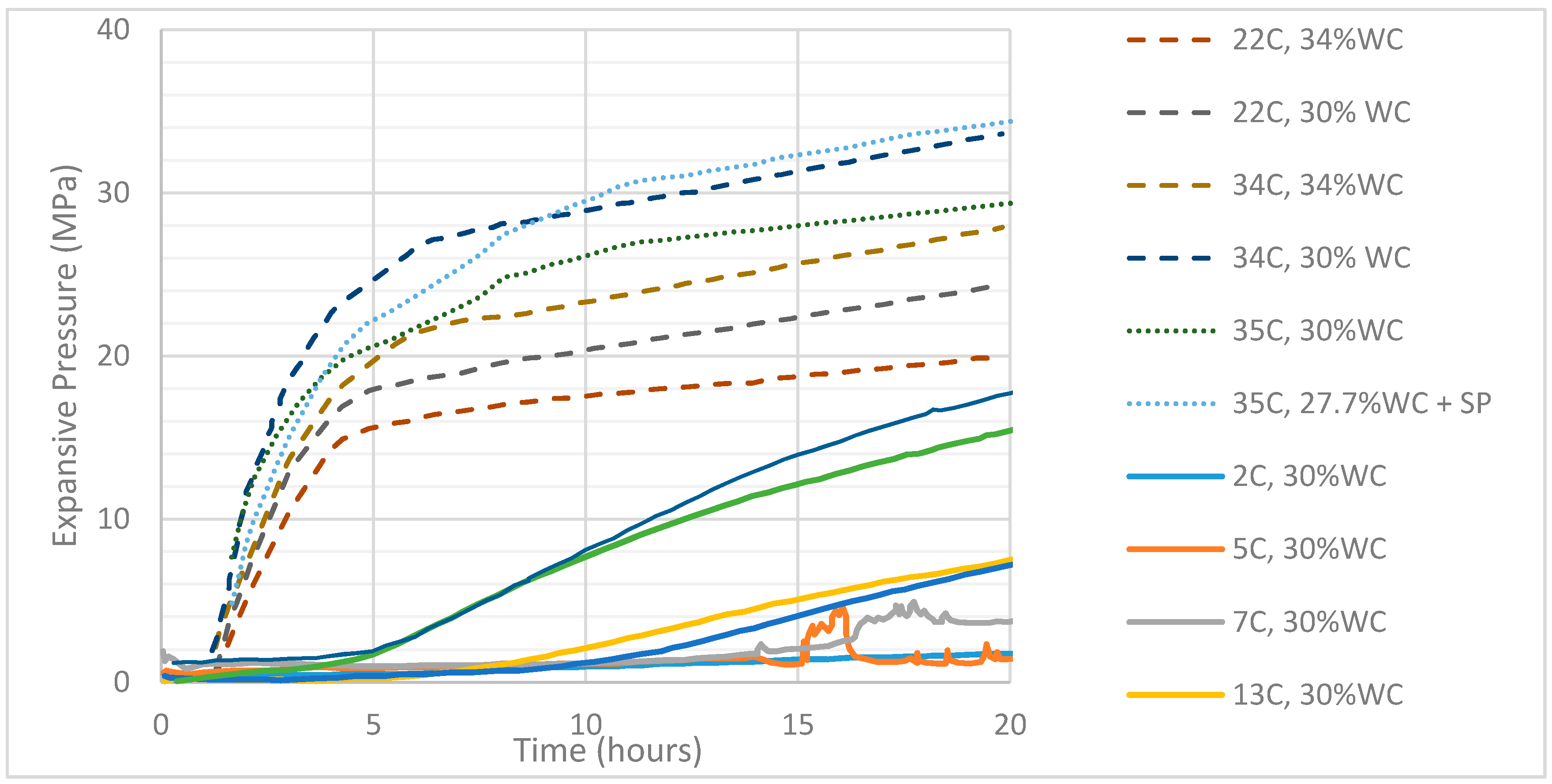
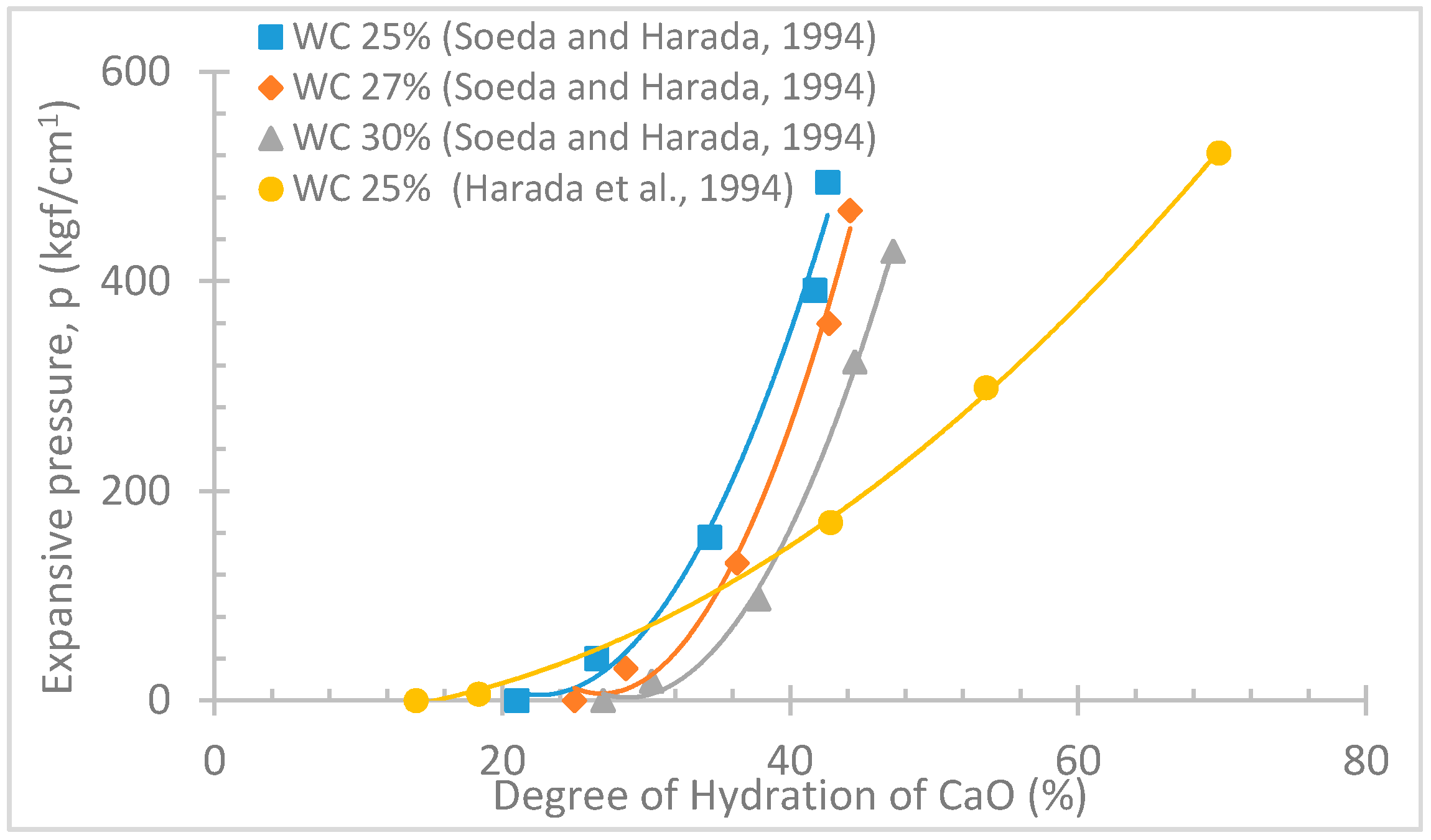
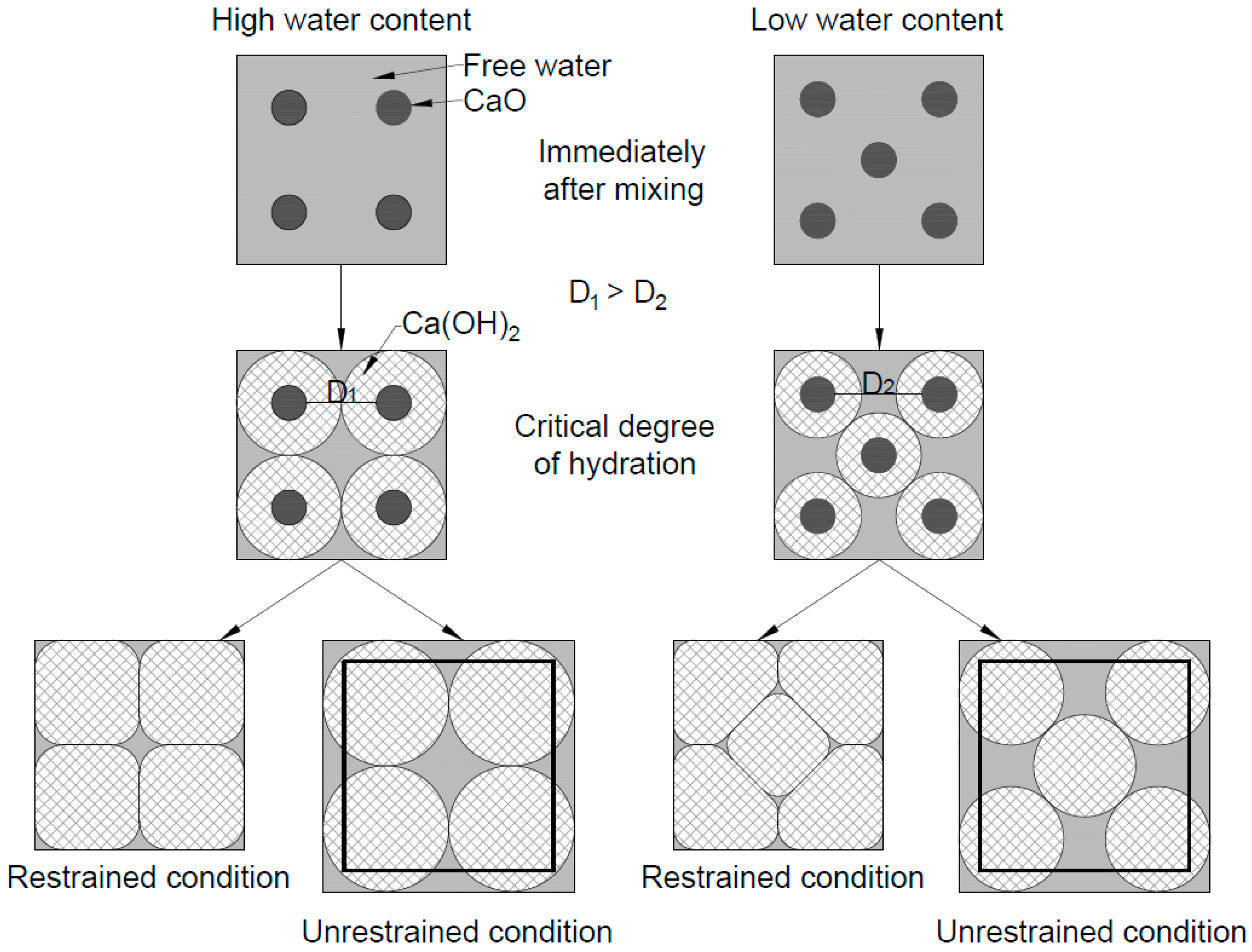
3.1. Influence of Water Content and Degree of Hydration
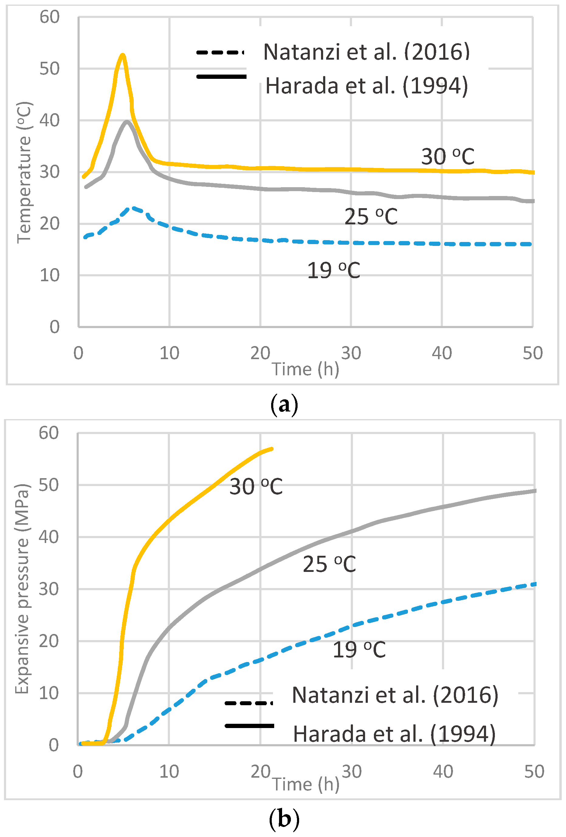
3.2. Influence of Ambient Temperature
3.3. Influence of Borehole Diameter
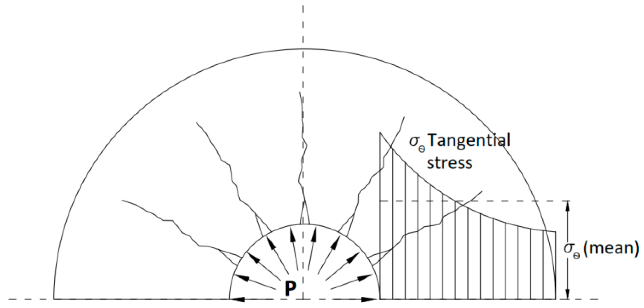
4. Volume Expansion Mechanism
5. Soundless Chemical Demolition Agent Generated Crack Propagation
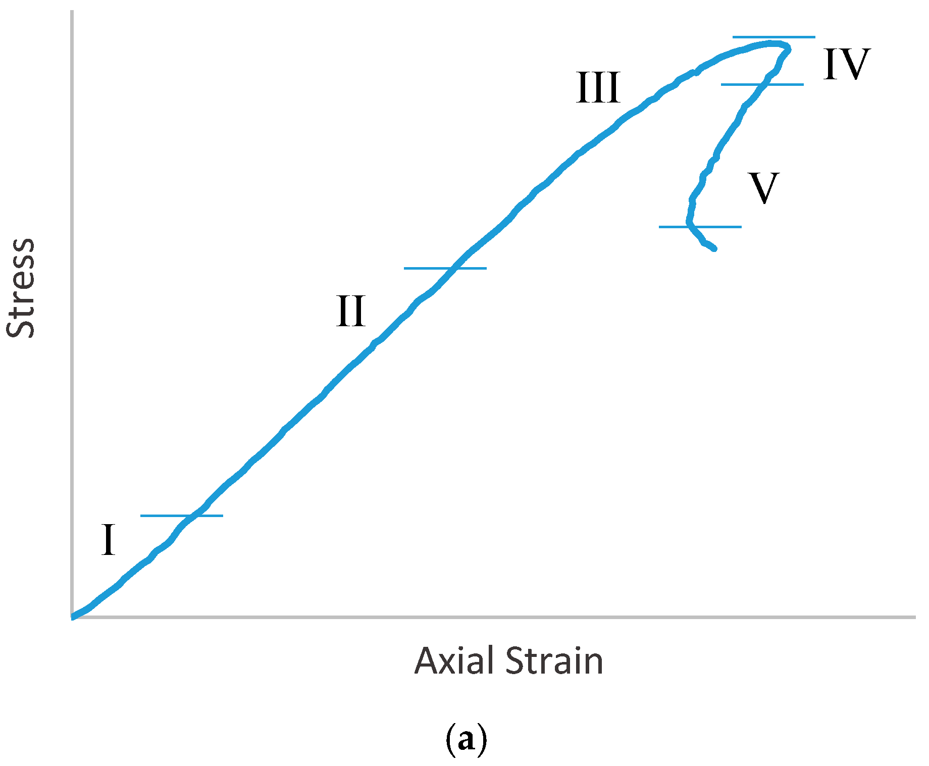
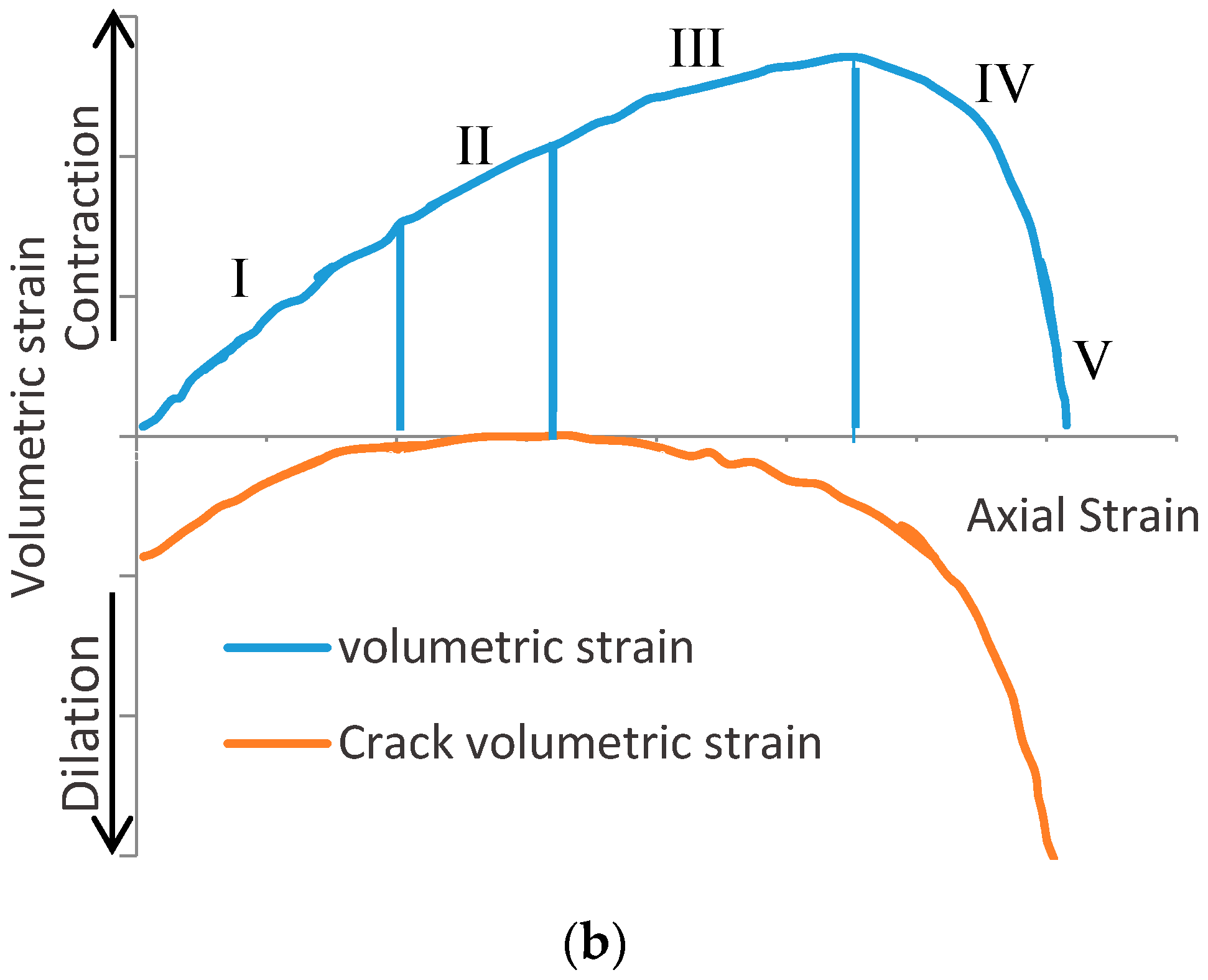
5.1. Brittle Failure of Rock
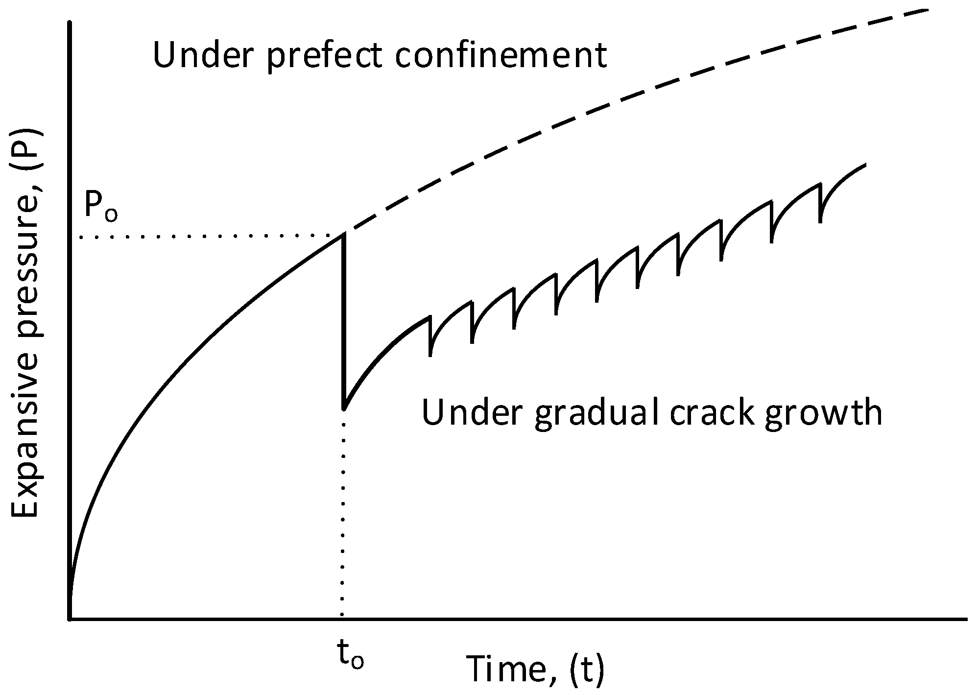
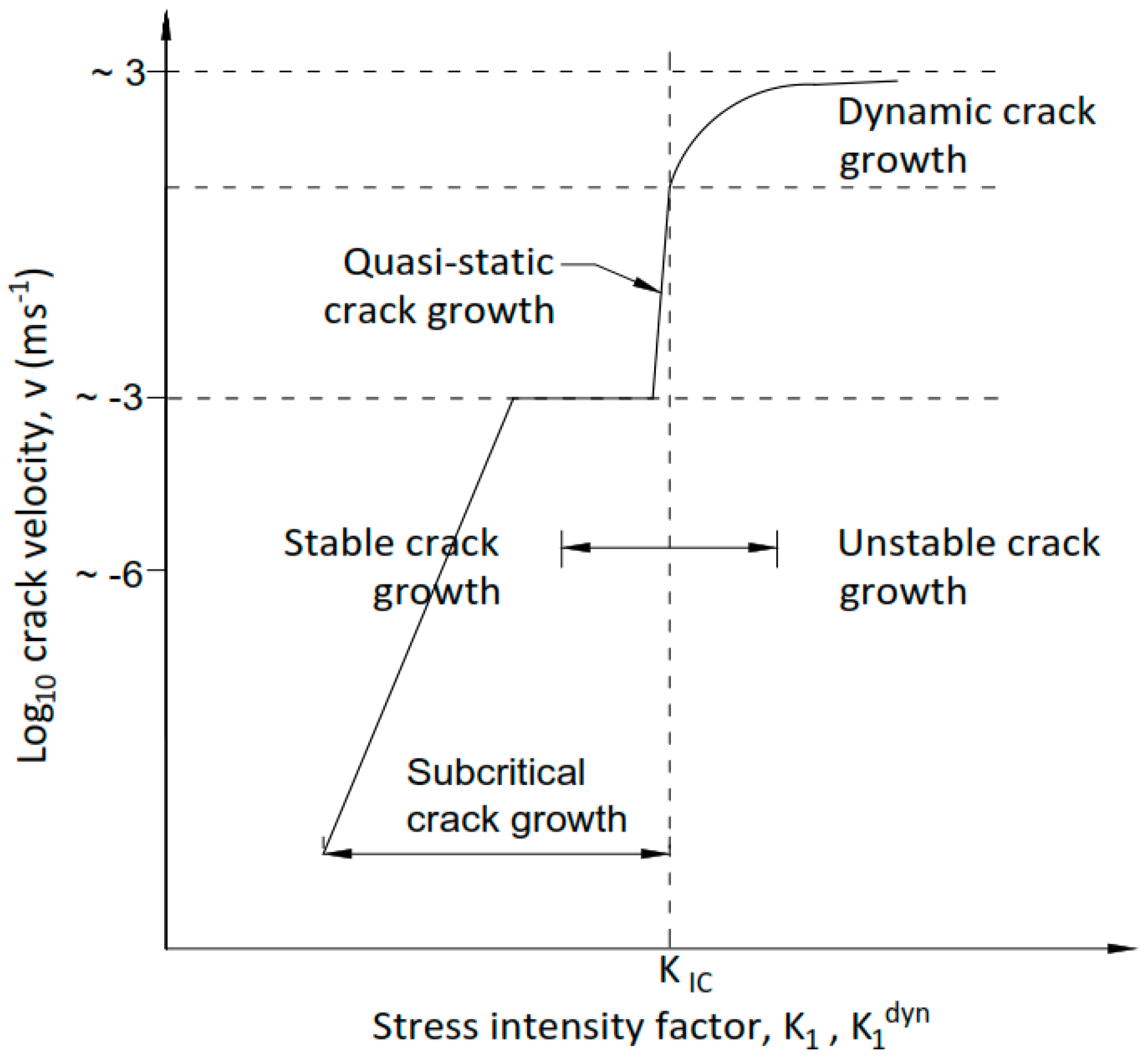
Quasi-Static Fracture Propagation
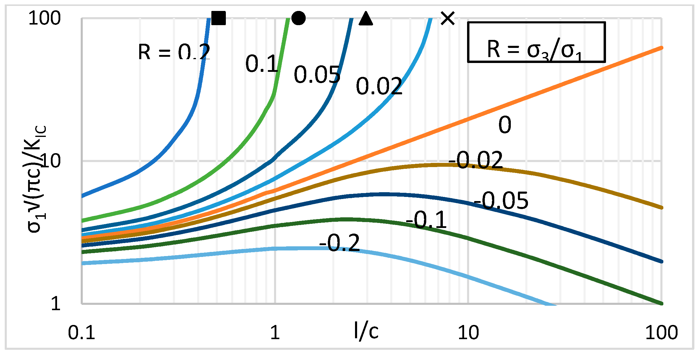
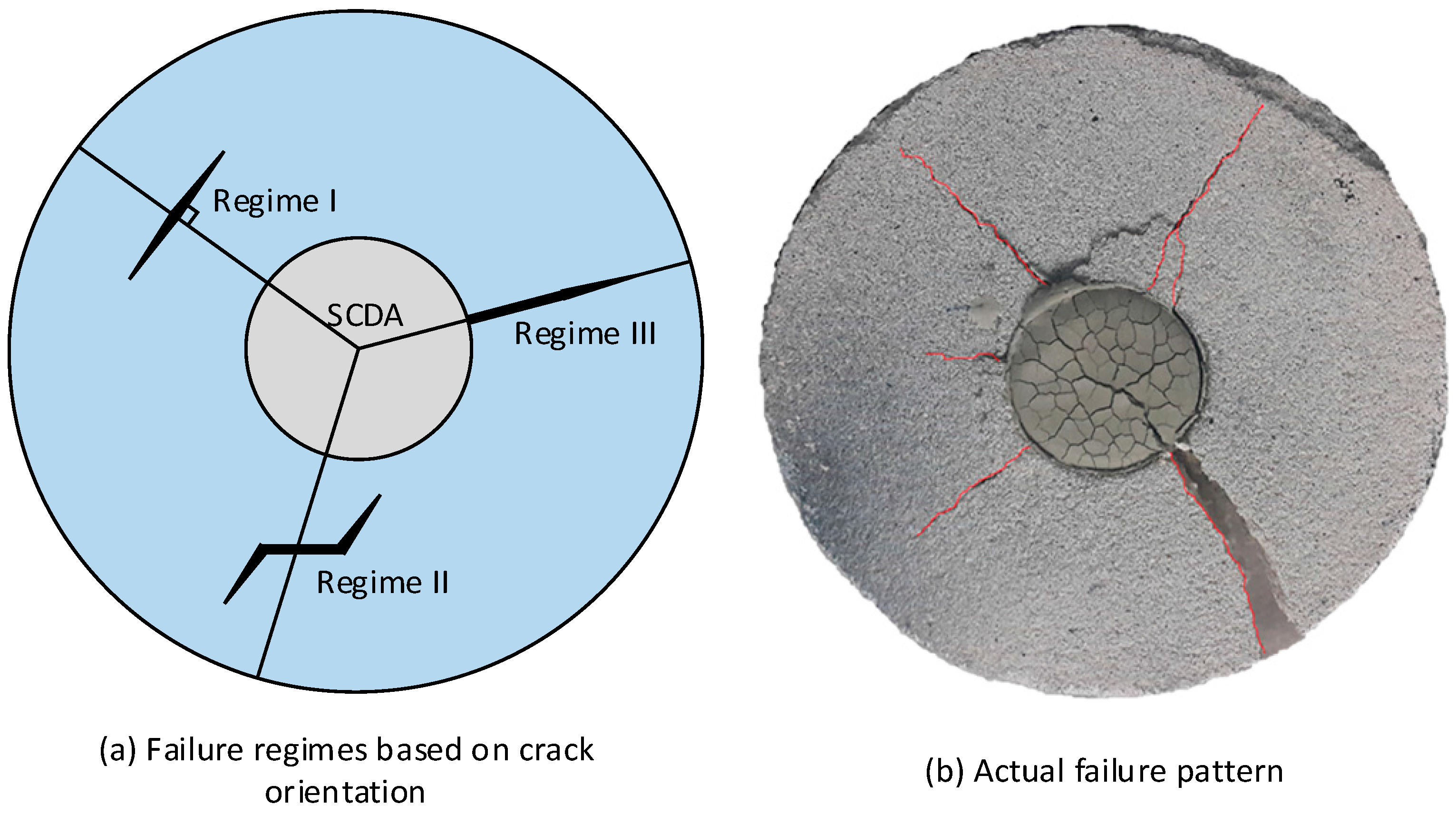
5.2. Modelling of SCDA Creating Damage Mechanism
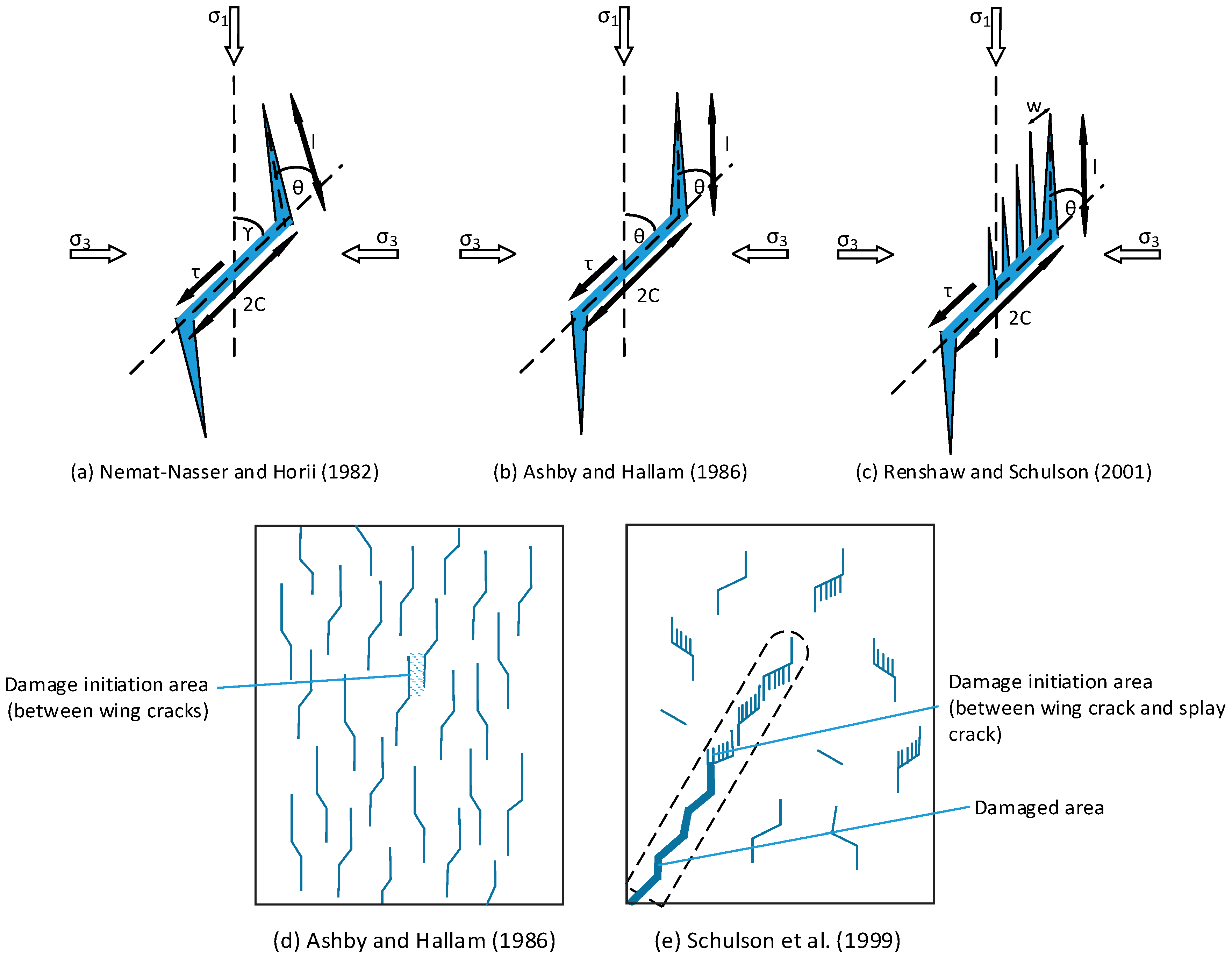
Microcrack Based Sliding Crack Models
- Regime I: no relative sliding along the faces of the inclined crack implying sufficient confinement is provided to keep the flanks of the wing cracks shut and material behaviour is similar to that of an intact material
- Regime II: frictional sliding along the faces of the inclined crack causing wing crack extension
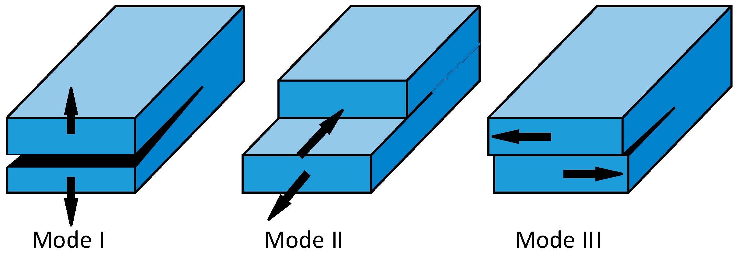
- Regime III: loss of contact between the faces of the inclined crack caused by the sufficiently tensile mean stress σm and the crack propagation is caused purely by mode I failure.
6. Optimum Usage Strategies for Soundless Chemical Demolition Agent
7. Potential Applications of Soundless Chemical Demolition Agent
8. Limitations and Possible Improvements for Soundless Chemical Demolition Agent
8.1. Washout Possibility
8.2. Flowability and Injectability
8.3. Performance in Deep Underground Conditions
9. Conclusions
- Though SCDA method is an effective alternative for conventional rock fragmentation methods such as hydraulic fracturing and explosive blasting (those having proven environmentally detrimental repercussions), there is a lack of research conducted on this aspect which is confirmed by the poor standards available on SCDA usage.
- During the fracturing process, inside confined quarters SCDA is subjected to huge volumetric expansion as a result of the associated chemical reaction (CaO hydration) and generates a large expansive pressure. Though this expansive pressure can be effectively used for the rock fragmentation process, proper quantification of it is necessary for a controllable effective rock fragmentation process. To date, several methods have therefore been reported in the literature to quantify the expansive pressure generated by SCDA, out of which the most widely used method being the outer pipe method.
- Quantifying the expansive pressure is complex due to its dependency on many factors including, water content, temperature and the arrangement of boreholes and its diameter. Among them, water content has a dominant influence on expansive pressure generation in SCDA, where high water contents require a higher degree of hydration of Ca(OH)2 to generate a particular expansive pressure, which therefore has a negative influence on expansive pressure generation. This Ca(OH)2 hydration process, however, also depends on the ambient temperature and borehole diameter, which are basically related to the heat of hydration in SCDA. The correlation between water content, temperature, and well diameter, degree of hydration and expansive pressure development has been well explained using Shalom’s volume expansion mechanism for SCDA.
- Having a precise understanding of the fracture propagation mechanisms when using SCDA is imperative due to the generation of complex fracture networks by SCDA fracking in rocks. To date, some micromechanics based sliding crack models have been developed based on the tangential and radial stresses acting on the surrounded rock mass (conditions similar to boreholes charged with SCDA) and show the compatibility of SCDA fracturing mechanisms with the quasi-static fracturing mechanism that occur in Mode I type tensile failure.
- However, available fracture models in the literature haven’t been developed exclusively for SCDA fracturing and instead existing micromechanics based fracture models have been used to identify the crack initiation, propagation and arrest criterions occur during the SCDA fracking.
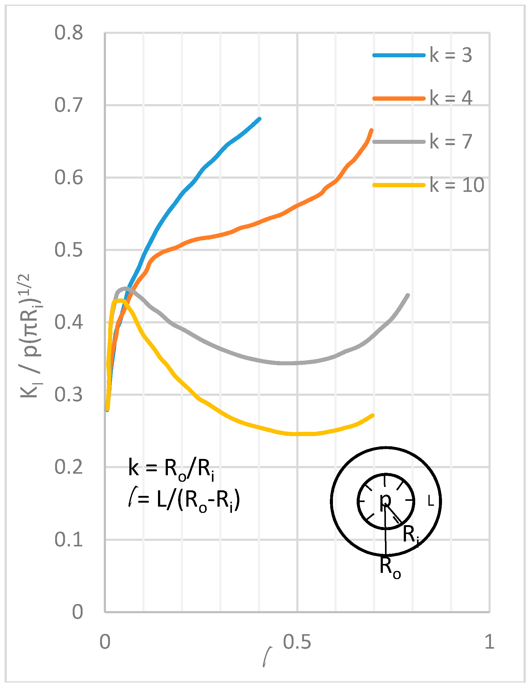
- The effect of borehole diameter, spacing and the arrangement on expansive pressure generation and corresponding fracture network generation play a significant role in SCDA fracturing process and effective handling of them would make way to create an optimum fracture network in a targeted rock formation and therefore has been largely considered in the literature with many proposed models.
- SCDAs can be effectively utilized in many petroleum engineering (unconventional oil and gas recovery) and mineral processing (in-situ leaching of minerals) applications and such application can be promoted through manipulating the ability of SCDA to form controlled fracture networks. However, further extensive investigation of the performance of SCDA with respect to its potential applications are in need, particularly considering the issues in using SCDA such as washout effects in deep saturated rock high strata temperatures and high salinity in saline aquifers.
Acknowledgments
Author Contributions
Conflicts of Interest
References
- World Bank. Energy Use (kg of Oil Equivalent Per Capita) Data. Available online: http://data.worldbank.org/indicator/EG.USE.PCAP.KG.OE (accessed on 15 June 2016).
- Energy Information Administration. International Energy Outlook 2016; Energy Information Administration: Washington, DC, USA, 2016.
- Fan, J.; Dou, L.; He, H.; Du, T.; Zhang, S.; Gui, B.; Sun, X. Directional hydraulic fracturing to control hard-roof rockburst in coal mines. Int. J. Min. Sci. Technol. 2012, 22, 177–181. [Google Scholar] [CrossRef]
- Wang, F.; Tu, S.; Yuan, Y.; Feng, Y.; Chen, F.; Tu, H. Deep-hole pre-split blasting mechanism and its application for controlled roof caving in shallow depth seams. Int. J. Rock Mech. Min. Sci. 2013, 64, 112–121. [Google Scholar] [CrossRef]
- Harada, T.; Idemitsu, T.; Watanabe, A.; Takayama, S.-I. The design method for the demolition of concrete with expansive demolition agents. In Fracture Concrete and Rock; Springer: Berlin, Germany, 1989; pp. 47–57. [Google Scholar]
- Jahed Armaghani, D.; Tonnizam Mohamad, E.; Hajihassani, M.; Alavi Nezhad Khalil Abad, S.V.; Marto, A.; Moghaddam, M.R. Evaluation and prediction of flyrock resulting from blasting operations using empirical and computational methods. Eng. Comput. 2016, 32, 109–121. [Google Scholar] [CrossRef]
- Mohamad, E.T.; Armaghani, D.J.; Hasanipanah, M.; Murlidhar, B.R.; Alel, M.N.A. Estimation of air-overpressure produced by blasting operation through a neuro-genetic technique. Environ. Earth Sci. 2016, 75, 1–15. [Google Scholar]
- Monjezi, M.; Hasanipanah, M.; Khandelwal, M. Evaluation and prediction of blast-induced ground vibration at shur river dam, iran, by artificial neural network. Neural Comput. Appl. 2013, 22, 1637–1643. [Google Scholar] [CrossRef]
- Monjezi, M.; Rezaei, M.; Yazdian, A. Prediction of backbreak in open-pit blasting using fuzzy set theory. Expert Syst. Appl. 2010, 37, 2637–2643. [Google Scholar] [CrossRef]
- Scoble, M.; Lizotte, Y.; Paventi, M.; Mohanty, B. Measurement of blast damage. Min. Eng. 1997, 49, 103–108. [Google Scholar]
- Zhi, S.; Elsworth, D. The role of gas desorption on gas outbursts in underground mining of coal. Geomech. Geophys. Geo-Energy Geo-Resour. 2016, 2, 151–171. [Google Scholar] [CrossRef]
- Hasanipanah, M.; Armaghani, D.J.; Monjezi, M.; Shams, S. Risk assessment and prediction of rock fragmentation produced by blasting operation: A rock engineering system. Environ. Earth Sci. 2016, 75, 1–12. [Google Scholar] [CrossRef]
- Morin, M.A.; Ficarazzo, F. Monte carlo simulation as a tool to predict blasting fragmentation based on the kuz-ram model. Comput. Geosci. 2006, 32, 352–359. [Google Scholar] [CrossRef]
- Donaldson, E.C.; Alam, W.; Begum, N. Hydraulic Fracturing Explained: Evaluation, Implementation, and Challenges; Elsevier: Amsterdam, The Netherlands, 2014. [Google Scholar]
- Smith, M.B.; Montgomery, C. Hydraulic Fracturing; CRC Press: Boca Raton, FL, USA, 2015. [Google Scholar]
- Arthur, J.D.; Uretsky, M.; Wilson, P. Water Resources and Use for Hydraulic Fracturing in the Marcellus Shale Region; ALL Consulting: Tulsa, OK, USA, 2010. [Google Scholar]
- Kondash, A.; Vengosh, A. Water footprint of hydraulic fracturing. Environ. Sci. Technol. Lett. 2015, 2, 276–280. [Google Scholar] [CrossRef]
- Winter, T.C. Ground Water and Surface Water: A Single Resource; DIANE Publishing: Darby, PA, USA, 1998. [Google Scholar]
- Guglielmi, Y.; Cappa, F.; Avouac, J.-P.; Henry, P.; Elsworth, D. Seismicity triggered by fluid injection–induced aseismic slip. Science 2015, 348, 1224–1226. [Google Scholar] [CrossRef] [PubMed] [Green Version]
- Ellsworth, W.L. Injection-induced earthquakes. Science 2013, 341, 1225942. [Google Scholar] [CrossRef] [PubMed]
- Holland, A.A. Earthquakes triggered by hydraulic fracturing in south-central oklahoma. Bull. Seismol. Soc. Am. 2013, 103, 1784–1792. [Google Scholar] [CrossRef]
- Osborn, S.G.; Vengosh, A.; Warner, N.R.; Jackson, R.B. Methane contamination of drinking water accompanying gas-well drilling and hydraulic fracturing. Proc. Natl. Acad. Sci. USA 2011, 108, 8172–8176. [Google Scholar] [CrossRef] [PubMed]
- Cooley, H.; Donnelly, K.; Ross, N.; Luu, P. Hydraulic Fracturing and Water Resources: Separating the Frack from the Fiction; Pacific Institute: Oakland, CA, USA, 2012. [Google Scholar]
- Environmental Protection Agency. Study of the Potential Impacts of Hydraulic Fracturing on Drinking Water Resources; Environmental Protection Agency: Washington, DC, USA, 2012.
- Wanniarachchi, W.; Ranjith, P.; Perera, M.; Lashin, A.; Al Arifi, N.; Li, J. Current opinions on foam-based hydro-fracturing in deep geological reservoirs. Geomech. Geophys. Geo-Energy Geo-Resour. 2015, 1, 121–134. [Google Scholar] [CrossRef]
- Waxman, H.A.; Markey, E.J.; DeGette, D. Chemicals Used in Hydraulic Fracturing; United States House of Representatives COEAC: Washington, DC, USA, 2011.
- Palmer, C.; Sito, Z. Nitrogen and carbon dioxide fracturing fluids for the stimulation of unconventional shale plays. AGH Drill. Oil Gas 2013, 30, 191–198. [Google Scholar] [CrossRef]
- McAndrew, J.; Fan, R.; Barba, R. Energized and Foam Fracturing Fluids for Liquids-Rich Organic Shale Reservoirs; Integrated Energy Services: Austin, TX, USA, 2014. [Google Scholar]
- Andres, U. Electrical disintegration of rock. Miner. Proc. Extr. Metall. Rev. 1995, 14, 87–110. [Google Scholar] [CrossRef]
- Andres, U. Development and prospects of mineral liberation by electrical pulses. Int. J. Miner. Proc. 2010, 97, 31–38. [Google Scholar] [CrossRef]
- Hirotoshi, I.; Igor, V.L.; Hidenori, A.; Izumi, N. Pulsed electric breakdown and destruction of granite. Jpn. J. Appl. Phys. 1999, 38, 6502. [Google Scholar]
- Kuznetsov, Y.I.; Vazhov, V.F.; Zhurkov, M.Y. Electrical breakdown of solid dielectrics and rocks on the trailing edge of a voltage pulse. Russ. Phys. J. 2011, 54, 410–415. [Google Scholar] [CrossRef]
- Lisitsyn, I.; Inoue, H.; Nishizawa, I.; Katsuki, S.; Akiyama, H. Breakdown and destruction of heterogeneous solid dielectrics by high voltage pulses. J. Appl. Phys. 1998, 84, 6262–6267. [Google Scholar] [CrossRef]
- Arshadnejad, S.; Goshtasbi, K.; Aghazadeh, J. A model to determine hole spacing in the rock fracture process by non-explosive expansion material. Int. J. Miner. Metall. Mater. 2011, 18, 509–514. [Google Scholar] [CrossRef]
- El Dessouki, A.; Mitri, H. Rock breakage using expansive cement. Engineering 2011, 3, 168. [Google Scholar] [CrossRef]
- Gambatese, J.A. Controlled concrete demolition using expansive cracking agents. J. Constr. Eng. Manag. 2003, 129, 98–104. [Google Scholar] [CrossRef]
- Harada, T.; Soeda, K.; Idemitsu, T.; Watanabe, A. Characteristics of Expansive Pressure of an Expansive Demolition Agent and the Development of New Pressure Transducers; Japan Society of Civil Engineers: Tokyo, Japan, 1994. [Google Scholar]
- Hinze, J.; Nelson, A. Enhancing performance of soundless chemical demolition agents. J. Constr. Eng. Manag. 1996, 122, 193–195. [Google Scholar] [CrossRef]
- Laefer, D.F.; Ceribasi, S.; Wortman, J.; Abrozevitch-Cooper, N.; Huynh, M.-P.; Midgette, J. Expansive fracture agent behaviour for concrete cracking. Mag. Concr. Res. 2010, 62, 443–452. [Google Scholar] [CrossRef]
- Natanzi, A.S.; Laefer, D.F.; Connolly, L. Cold and moderate ambient temperatures effects on expansive pressure development in soundless chemical demolition agents. Constr. Build. Mater. 2016, 110, 117–127. [Google Scholar] [CrossRef]
- Hinze, J.; Brown, J. Properties of soundless chemical demolition agents. J. Constr. Eng. Manag. 1994, 120, 816–827. [Google Scholar] [CrossRef]
- Huynh, M.-P.; Laefer, D.F. Expansive cements and soundless chemical demolition agents: State of technology review. In Proceedings of the 11th Conference on Science and Technology, Ho Chi Minh City, Vietnam, 21–23 October 2009.
- Betanomit Technical Manual-Non Explosive Cracking Agent. Available online: http://www.betonamit.com/technical-manual/ (accessed on 8 April 2016).
- Bristar (for General Purpose/Bulk Type) Non-Explosive Demolition Agent Taiheiyo Materials Corporation. Available online: http://www.taiheiyo-m.co.jp/english/product/productSubtop_4/product_4/productEntry-e023.html (accessed on 8 April 2016).
- Archer USA. Available online: http://www.dexpan.com/dexpan-non-explosive-controlled-demolition-agent-silent-cracking-breaking.aspx (accessed on 5 October 2016).
- Expando, Expansive Mortar, Non Explosive Demolition Agent Used for Rock, Concrete Breaking. Available online: http://www.expando.com.au/what-is-expando (accessed on 8 April 2016).
- Ecobust. Available online: http://www.ecobust.com/ (accessed on 8 April 2016).
- Nagataki, S.; Gomi, H. Expansive admixtures (mainly ettringite). Cem. Concr. Compos. 1998, 20, 163–170. [Google Scholar] [CrossRef]
- Konik, Z.; Małolepszy, J.; Roszczynialski, W.; Stok, A. Production of expansive additive to portland cement. J. Eur. Ceram. Soc. 2007, 27, 605–609. [Google Scholar] [CrossRef]
- Standard Specification for Expansive Hydraulic Cement; ASTM International: West Conshohocken, PA, USA, 1996.
- Soeda, K.; Harada, T. The mechanics of expansive pressure generation using expansive demolition agent. Doboku Gakkai Ronbunshu 1993, 1993, 89–96. [Google Scholar] [CrossRef]
- Liu, X.; Li, Y. Effect of mgo on the composition and properties of alite-sulphoaluminate cement. Cem. Concr. Res. 2005, 35, 1685–1687. [Google Scholar] [CrossRef]
- Horkoss, S.; Escadeillas, G.; Rizk, T.; Lteif, R. The effect of the source of cement SO 3 on the expansion of mortars. Case Stud. Constr. Mater. 2016, 4, 62–72. [Google Scholar] [CrossRef]
- Kurdowski, W.; Thiel, A. On the role of free calcium oxide in expansive cements. Cem. Concr. Res. 1981, 11, 29–40. [Google Scholar] [CrossRef]
- Bentur, A.; Ish-Shalom, M. Properties of type k expensive cement of pure components II: Proposed mechanism of ettringite formation and expansion in unrestrained paste of pure expansive component. Cem. Concr. Res. 1974, 4, 709–721. [Google Scholar] [CrossRef]
- Chatterji, S. Mechanism of expansion of concrete due to the presence of dead-burnt cao and mgo. Cem. Concr. Res. 1995, 25, 51–56. [Google Scholar] [CrossRef]
- Ish-Shalom, M.; Bentur, A. Properties of type k expansive cement of pure components I: Hydration of unrestrained paste of expansive component-Results. Cem. Concr. Res. 1974, 4, 519–532. [Google Scholar] [CrossRef]
- Nocuń-Wczelik, W.; Stok, A.; Konik, Z. Heat evolution in hydrating expansive cement systems. J. Therm. Anal. Calorim. 2010, 101, 527–532. [Google Scholar] [CrossRef]
- Ghosh, S. Cement and Concrete Science and Technology; Thomas Telford: Telford, UK, 1991. [Google Scholar]
- Gómez, C.; Mura, T. Stresses caused by expansive cement in borehole. J. Eng. Mech. 1984, 110, 1001–1005. [Google Scholar] [CrossRef]
- Mehta, P.; Lesnikoff, G. Hydration characteristics and properties of shrinkage-compensating cements. In Proceedings of the 6th International Congress on the Chemistry of Cement, Moscow, Russia, 23–27 September 1974; pp. 89–115.
- Polivka, M. Factors Influencing Expansion of Expansive Cement Concretes; Special Publications; Symantec Endpoint Protection Manager: Darlington, UK, 1973; Volume 38, pp. 239–250. [Google Scholar]
- Boresi, A.P.; Chong, K.P. Elasticity in Engineering Mechanics; Elsevier Science Publishing Co., Inc.: New York, NY, USA, 1987. [Google Scholar]
- Dowding, C.H.; Labuz, J.F. Closure to “fracturing of rock with expansive cement” by Charles H. Dowding and Joseph F. Labuz (October 1982). J. Geotech. Eng. 1983, 109, 1208–1209. [Google Scholar] [CrossRef]
- Cohen, M. Modeling of expansive cements. Cem. Concr. Res. 1983, 13, 519–528. [Google Scholar] [CrossRef]
- Ish-Shalom, M.; Bentur, A. Properties of type k expansive cement of pure components III: Hydration of pure expansive component under varying restraining conditions. Cem. Concr. Res. 1975, 5, 139–152. [Google Scholar] [CrossRef]
- Kadri, E.; Aggoun, S.; De Schutter, G.; Ezziane, K. Combined effect of chemical nature and fineness of mineral powders on portland cement hydration. Mater. Struct. 2010, 43, 665–673. [Google Scholar] [CrossRef]
- Dehghan, A.N.; Goshtasbi, K.; Ahangari, K.; Jin, Y. Experimental investigation of hydraulic fracture propagation in fractured blocks. Bull. Eng. Geol. Environ. 2015, 74, 887–895. [Google Scholar] [CrossRef]
- Guo, T.; Zhang, S.; Ge, H.; Wang, X.; Lei, X.; Xiao, B. A new method for evaluation of fracture network formation capacity of rock. Fuel 2015, 140, 778–787. [Google Scholar] [CrossRef]
- Mogi, K. Pressure Dependence of Rock Strength and Transition from Brittle Fracture to Ductile Flow; Earthquake Research Institute, University of Tokyo: Tokyo, Japan, 1966. [Google Scholar]
- Klein, E.; Baud, P.; Reuschlé, T.; Wong, T. Mechanical behaviour and failure mode of bentheim sandstone under triaxial compression. Phys. Chem. Earth A Solid Earth Geod. 2001, 26, 21–25. [Google Scholar] [CrossRef]
- Paquet, J.; François, P. Experimental deformation of partially melted granitic rocks at 600–900 c and 250 mpa confining pressure. Tectonophys 1980, 68, 131–146. [Google Scholar] [CrossRef]
- Bieniawski, Z.T. Mechanism of brittle fracture of rock. Int. J. Rock Mech. Min. Sci. Geomech. Abstr. 1967, 4, 395–406. [Google Scholar] [CrossRef]
- Brace, W.F.; Paulding, B.W.; Scholz, C. Dilatancy in the fracture of crystalline rocks. J. Geophys. Res. 1966, 71, 3939–3953. [Google Scholar] [CrossRef]
- Hallbauer, D.; Wagner, H.; Cook, N. Some observations concerning the microscopic and mechanical behaviour of quartzite specimens in stiff, triaxial compression tests. Int. J. Rock Mech. Min. Sci. Geomech. Abstr. 1973, 10, 713–726. [Google Scholar] [CrossRef]
- Hoek, E.; Bieniawski, Z. Brittle fracture propagation in rock under compression. Int. J. Fract. Mech. 1965, 1, 137–155. [Google Scholar] [CrossRef]
- Martin, C.; Chandler, N. The progressive fracture of lac du bonnet granite. Int. J. Rock Mech. Min. Sci. Geomech. Abstr. 1994, 31, 643–659. [Google Scholar] [CrossRef]
- Scholz, C. Experimental study of the fracturing process in brittle rock. J. Geophys. Res. 1968, 73, 1447–1454. [Google Scholar] [CrossRef]
- Tapponnier, P.; Brace, W. Development of stress-induced microcracks in westerly granite. Int. J. Rock Mech. Min. Sci. Geomech. Abstr. 1976, 13, 103–112. [Google Scholar] [CrossRef]
- Wawersik, W.; Brace, W. Post-failure behavior of a granite and diabase. Rock Mech. 1971, 3, 61–85. [Google Scholar] [CrossRef]
- Brace, W.F. Brittle fracture of rocks. In State of Stress in the Earth’s Crust; Elsevier: New York, NY, USA, 1964; pp. 111–180. [Google Scholar]
- Chang, S.-H.; Lee, C.-I.; Jeon, S. Measurement of rock fracture toughness under modes I and II and mixed-mode conditions by using disc-type specimens. Eng. Geol. 2002, 66, 79–97. [Google Scholar] [CrossRef]
- Irwin, G.R. Analysis of stresses and strains near the end of a crack traversing a plate. J. Appl. Mech. 1957, 24, 361–364. [Google Scholar]
- Atkinson, B.K. Introduction to fracture mechanics and its geophysical applications. Fract. Mech. Rock 1987, 1–26. [Google Scholar] [CrossRef]
- Clifton, R.J.; Simonson, E.R.; Jones, A.H.; Green, S.J. Determination of the critical-stress-intensity factor kic from internally pressurized thick-walled vessels. Exp. Mech. 1976, 16, 233–238. [Google Scholar] [CrossRef]
- Atkinson, B.K. Subcritical crack growth in geological materials. J. Geophys. Res. Solid Earth 1984, 89, 4077–4114. [Google Scholar] [CrossRef]
- Lockner, D.A.; Madden, T.R. A multiple-crack model of brittle fracture: 2. Time-dependent simulations. J. Geophys. Res.Solid Earth 1991, 96, 19643–19654. [Google Scholar] [CrossRef]
- Bieniawski, Z.T. Fracture dynamics of rock. Int. J. Fract. Mech. 1968, 4, 415–430. [Google Scholar] [CrossRef]
- Brace, W.F.; Bombolakis, E.G. A note on brittle crack growth in compression. J. Geophys. Res. 1963, 68, 3709–3713. [Google Scholar] [CrossRef]
- Kachanov, M.L. A microcrack model of rock inelasticity part II: Propagation of microcracks. Mech. Mater. 1982, 1, 29–41. [Google Scholar] [CrossRef]
- Kachanov, M.L. A microcrack model of rock inelasticity part I: Frictional sliding on microcracks. Mech. Mater. 1982, 1, 19–27. [Google Scholar] [CrossRef]
- Nemat-Nasser, S.; Horii, H. Compression-induced nonplanar crack extension with application to splitting, exfoliation, and rockburst. J. Geophys. Res. Solid Earth 1982, 87, 6805–6821. [Google Scholar] [CrossRef]
- Horii, H.; Nemat-Nasser, S. Compression-induced microcrack growth in brittle solids: Axial splitting and shear failure. J. Geophys. Res 1985, 90, 3. [Google Scholar] [CrossRef]
- Nemat-Nasser, S.; Deng, H. Strain-rate effect on brittle failure in compression. Acta Metall. Mater. 1994, 42, 1013–1024. [Google Scholar] [CrossRef]
- Renshaw, C.E.; Schulson, E.M. Universal behaviour in compressive failure of brittle materials. Nature 2001, 412, 897–900. [Google Scholar] [CrossRef] [PubMed]
- Schulson, E.M.; Iliescu, D.; Renshaw, C.E. On the initiation of shear faults during brittle compressive failure: A new mechanism. J. Geophys. Res. Solid Earth 1999, 104, 695–705. [Google Scholar] [CrossRef]
- Ashby, M.F.; Hallam, S.D. The failure of brittle solids containing small cracks under compressive stress states. Acta Metall. 1986, 34, 497–510. [Google Scholar] [CrossRef]
- Rose, L. Effective fracture toughness of microcracked materials. J. Am. Ceram. Soc. 1986, 69, 212–214. [Google Scholar] [CrossRef]
- Sammis, C.; Ashby, M. The failure of brittle porous solids under compressive stress states. Acta Metall. 1986, 34, 511–526. [Google Scholar] [CrossRef]
- Ashby, M.; Sammis, C. The damage mechanics of brittle solids in compression. Pure Appl. Geophys. 1990, 133, 489–521. [Google Scholar] [CrossRef]
- Deshpande, V.; Evans, A. Inelastic deformation and energy dissipation in ceramics: A mechanism-based constitutive model. J. Mech. Phys. Solids 2008, 56, 3077–3100. [Google Scholar] [CrossRef]
- Zhongzhe, J.; Hong, L.; Wen, Z.; Kasai, Y. Splitting mechanism of rock and concrete under expansive pressure. In Proceedings of the Conference of Demolition and Reuse of Concrete and Masonry, Demolition Method and Practice, Tokyo, Japan, 7–11 November 1988; pp. 141–148.
- Wang, Y.S.; You, B.K.; Zhang, G.Q. Application of soundless cracking agent in china. In Demolition and Reuse of Concrete and Masonry; Chemical Rubber Company Press: Abingdon, UK, 1988; p. 149. [Google Scholar]
- Jin, Z.Z.; Liao, H.; Zhu, W. Splitting mechanism of rock and concrete under expansive pressure. In Demolition and Reuse of Concrete and Masonry; Chemical Rubber Company Press: Abingdon, UK, 1988; p. 141. [Google Scholar]
- Natanzi, A.S.; Laefer, D.F. Using chemicals as demolition agents near historic structures. In Proceedings of the 9th International Conference on Structural Analysis of Historical Constructions, Mexico City, Mexico, 14–17 October 2014.
- Musunuri, A.; Mitri, H. Laboratory investigation into rock fracturing with expansive cement. Int. J. Min. Miner. Eng. 2009, 1, 327–345. [Google Scholar] [CrossRef]
- Guo, T.; Zhang, S.; Ge, H.; Qu, Z. A novel “soundless cracking agent fracturing” for shale gas reservoir stimulation. Int. J. Environ. Sci. Dev. 2015, 6, 681. [Google Scholar] [CrossRef]
- Australia’s Identified Mineral Resources 2013; No. 78988; Geoscience Australia: Canberra, Australia, 2014.
- Khayat, K.H. Viscosity-enhancing admixtures for cement-based materials—An overview. Cem. Concr. Compos. 1998, 20, 171–188. [Google Scholar] [CrossRef]
- Lachemi, M.; Hossain, K.; Lambros, V.; Nkinamubanzi, P.-C.; Bouzoubaâ, N. Self-consolidating concrete incorporating new viscosity modifying admixtures. Cem. Concr. Res. 2004, 34, 917–926. [Google Scholar] [CrossRef]
- Patural, L.; Marchal, P.; Govin, A.; Grosseau, P.; Ruot, B.; Deves, O. Cellulose ethers influence on water retention and consistency in cement-based mortars. Cem. Concr. Res. 2011, 41, 46–55. [Google Scholar] [CrossRef] [Green Version]
- Xu, L.; Xu, G.; Liu, T.; Chen, Y.; Gong, H. The comparison of rheological properties of aqueous welan gum and xanthan gum solutions. Carbohydr. Polym. 2013, 92, 516–522. [Google Scholar] [CrossRef] [PubMed]
- Plank, J.; Hirsch, C. Impact of zeta potential of early cement hydration phases on superplasticizer adsorption. Cem. Concr. Res. 2007, 37, 537–542. [Google Scholar] [CrossRef]
- Hekal, E.E.; Kishar, E.A. Effect of sodium salt of naphthalene-formaldehyde polycondensate on ettringite formation. Cem. Concr. Res. 1999, 29, 1535–1540. [Google Scholar] [CrossRef]
- Zhou, X.; Lin, X.; Huo, M.; Zhang, Y. The hydration of saline oil-well cement. Cem. Concr. Res. 1996, 26, 1753–1759. [Google Scholar] [CrossRef]
- Nasvi, M.; Ranjith, P.; Sanjayan, J.; Haque, A.; Li, X. Mechanical behaviour of wellbore materials saturated in brine water with different salinity levels. Energy 2014, 66, 239–249. [Google Scholar] [CrossRef]
- Rocha, C.A.A.; Simão, C.A.; Cordeiro, G.C.; Toledo Filho, R.D. Effect of the sodium and potassium chloride on the mechanical and plastic properties on the oil well cement slurries. In Proceedings of the 31st International Conference on Ocean, Offshore and Arctic Engineering, Rio de Janeiro, Brazil, 10–15 June 2012.
- Teodoriu, C.; Asamba, P. Experimental study of salt content effect on class g cement properties with application to well integrity. J. Nat. Gas Sci. Eng. 2015, 24, 324–329. [Google Scholar] [CrossRef]
- Suggate, R. Relations between depth of burial, vitrinite reflectance and geothermal gradient. J. Pet. Geol. 1998, 21, 5–32. [Google Scholar] [CrossRef]


| Product | Performance | Usage Instructions | Borehole Specification | |||
|---|---|---|---|---|---|---|
| Betonamit [43] Type R—liquid; for easy injection. Type S—Putty; for horizontal bore holes and when holes saturated with water | Cracking observed 12 h after injection [36] Maximum expansive pressure unavailable Recommended temperature from −5 °C to 35 °C | For fracturing of Limestone, Granite and Concrete. Water content of 20% Use within 5 min after mixing | Bore hole depth, h 4 × dia. < h < 3 m Drill depth 60~75% of desired crack depth. Spacing, 300~600 mm | |||
| Ambient | Max water | Material usage | Borehole diameter, D (mm) | temp. (°C) | ||
| temp. (°C) | temp. (°C) | Weight (kg/m) | Diameter (mm) | |||
| −4~4 | 43 | 2.2 | 38.0 | 38.0 | −4~4 | |
| 4~14 | 29 | 1.7 | 35.0 | 35.0~38.0 | 4~14 | |
| 14~22 | 18 | 1.5 | 32.0 | 32.0~38.0 | 14~22 | |
| 22~27 | 4 | 32.0~35.0 | 22~27 | |||
| 27~35 | 4 | 32.0 | 27~35 | |||
| Bristar [44] Bristar 100 Bristar 150 Bristar 200 Bristar 300 | Cracking observed 10~12 h after injection The expansive pressure of 30 MPa at room temp. after 16 h of injection Recommended temperature from −5 °C to 35 °C | For fracturing of rocks. Water content of 30% Use within 10 min after mixing | Drill depth 80% of desired crack depth. Bore hole depth, 3D < h Spacing, hard rock 400~600 mm soft rock 500~700 mm Bore hole diameter (mm) 36 < D < 50 | |||
| Material usage | ||||||
| Ambient temp. (°C) | Max water temp. (°C) | Weight (kg/m) | Diameter (mm) | |||
| 15~35 | 30 | 1.7 | 36 | |||
| 10~20 | 15 | 1.9 | 38 | |||
| 5~15 | 10 | 2.1 | 42 | |||
| −5~5 | 5 | |||||
| Dexpan [45] Dexpan I Dexpan II Dexpan III | Crack initiation time 2~8 h after injection | For fracturing of rock Water content of 30% Use within 10~15 mins. after mixing | Drill depth 80% of desired crack depth. Bore hole diameter (mm) D = 38 Spacing, ~300 mm | |||
| Maximum expansive pressure, 124 MPa | ||||||
| Recommended temperature from −5 °C to 40 °C | ||||||
| Material usage | ||||||
| Ambient temp. (°C) | Max water temp. (°C) | Weight (kg/m) | Diameter (mm) | |||
| 25~40 | N/A | 2 | 38 | |||
| 10~25 | N/A | |||||
| −5~10 | N/A | |||||
| Expando [46] SCA I SCA II SCA III | Crack completion 24 h Maximum expansive pressure, 96 MPa Recommended temperature from 0 °C to 35 °C | For fracturing of rock and concrete Water content of 30% Use within 10 min after mixing | Drill depth 80% of desired crack depth. Bore hole diameter (mm) 28 < D < 40 Spacing, 300~500 mm | |||
| Material usage | ||||||
| Ambient temp. (°C) | Max water temp. (°C) | Weight (kg/m) | Diameter (mm) | |||
| 20~35 | N/A | 1.3 | 32 | |||
| 10~25 | N/A | 1.5 | 34 | |||
| 0~15 | N/A | 1.8 | 38 | |||
| Ecobust [47] Type 1 Type 2 Type 3 Type 4 | Maximum expansive pressure, 137 MPa Recommended temperature from −8 °C to 35 °C | For fracturing of rock and concrete Use within 10 min after mixing | Drill depth 90% of desired crack depth for rock. Bore hole depth, 2D < h Bore hole diameter (mm) 38 < D < 50 Spacing, hard rock 200 mm soft rock 400 mm | |||
| Material usage | ||||||
| Ambient temp. (°C) | Max water temp. (°C) | Weight (kg/m) | Diameter (mm) | |||
| 20~35 | N/A | 1.7 | 38 | |||
| 20~25 | N/A | |||||
| 5~15 | N/A | |||||
| −8~5 | N/A | |||||
| Chemical Components | Percentage by Mass (%) |
|---|---|
| SiO2 | 1.5–8.5 |
| Al2O3 | 0.3–5.0 |
| Fe2O3 | 0.2–3.0 |
| CaO | 81–96 |
| MgO | 0–1.6 |
| SO3 | 0.6–4.0 |
| Refs. | Governing Equation | Remarks |
|---|---|---|
| [90] | l = wing crack length 2c = initial flaw length τ = Shear stress on the crack surface resulting from σ1 and σ3 (Figure 13 Simple 2D microcrack models) k ≈ 1.15 (variable) | The basic model developed by including the length of wing crack to determine the crack growth stress. |
| [92] | 2D model for crack initiation from pre-existing micro-fractures in the material. Sliding of crack faces causes mode 2 failure in crack tip initiating wing cracks. | |
| [99] | a = radius of micro-pore R = σ3/σ1 | Development of a fracture model for failure of brittle solids considering the interaction between cracks. Cracks are assumed to be initiation from micro-pores within the solid. Total stress intensity factor is a combination of a single crack growth and the effect of neighboring cracks. |
| [97] | R = σ3/σ1 Additional contribution caused by crack interaction Do = πc2 NA NA = Number of initial cracks per unit area | Similar to Nemat-Nasser and Horii [ 92] 2D model. The crack initiation model is extended by considering the additional contribution to the stress intensity due to bending of columns caused by crack interaction. |
| [100] | Do = π (αc)2 NA (initial dammage) D = π (l + αc)2 NA (Curent damage) α = cos(45°) (for cracks inclined 45° to the major principal stress) 2D crack extension model | Incorporates damage evolution into the model by including the length of wing crack l at constant confinement. The 2D crack model was extended to a 3D penny-shaped crack propagation model |
| [96] | α = l/w (Figure 13) | Applicable when only under uniaxial compression. Failure initiated from bending of microcolumns generated by splay cracking. |
| [95] | Developed from the Schulson et al. [96] model. Incorporates the frictional effect of adjacent microcolumns to model failure. Applicable under confined conditions when:
| |
| [101] | σm = (σ1 + σ3)/2 α = cos(45°) β = 0.1 σe = √3/2 (σ3 − σ1)γ = crack shape factor , Regime II | A generalized model for arbitrary stress states developed from Ashby and Sammis [100] model. Defines three regimes for applied confinement ratios depending on the crack surface interactions. |
© 2016 by the authors; licensee MDPI, Basel, Switzerland. This article is an open access article distributed under the terms and conditions of the Creative Commons Attribution (CC-BY) license (http://creativecommons.org/licenses/by/4.0/).
Share and Cite
De Silva, R.V.; Pathegama Gamage, R.; Anne Perera, M.S. An Alternative to Conventional Rock Fragmentation Methods Using SCDA: A Review. Energies 2016, 9, 958. https://doi.org/10.3390/en9110958
De Silva RV, Pathegama Gamage R, Anne Perera MS. An Alternative to Conventional Rock Fragmentation Methods Using SCDA: A Review. Energies. 2016; 9(11):958. https://doi.org/10.3390/en9110958
Chicago/Turabian StyleDe Silva, Radhika Vidanage, Ranjith Pathegama Gamage, and Mandadige Samintha Anne Perera. 2016. "An Alternative to Conventional Rock Fragmentation Methods Using SCDA: A Review" Energies 9, no. 11: 958. https://doi.org/10.3390/en9110958