
Segmentation of Concrete Cracks by Using Fractal Dimension and UHK-Net
by

Qing An
1, 
Xijiang Chen
1,2,*,
Haojun Wang
2,
Huamei Yang
1,*,
Yuanjun Yang
1,
Wei Huang
1 and
Lei Wang
3 1
School of Artificial Intelligence, Wuchang University of Technology, Wuhan 430223, China
2
School of Safety Science and Emergency Management, Wuhan University of Technology, Wuhan 430079, China
3
College of Materials Science and Engineering, Xi’an University of Architecture and Technology, Xi’an 710055, China
*
Authors to whom correspondence should be addressed.
Fractal Fract. 2022, 6(2), 95; https://doi.org/10.3390/fractalfract6020095
Submission received: 15 January 2022
/
Revised: 4 February 2022
/
Accepted: 7 February 2022
/
Published: 9 February 2022
(This article belongs to the Special Issue Fractal and Fractional in Cement-based Materials)
Abstract
:Concrete wall surfaces are prone to cracking for a long time, which affects the stability of concrete structures and may even lead to collapse accidents. In view of this, it is necessary to recognize and distinguish the concrete cracks. Then, the stability of concrete will be known. In this paper, we propose a novel approach by fusing fractal dimension and UHK-Net deep learning network to conduct the semantic recognition of concrete cracks. We first use the local fractal dimensions to study the concrete cracking and roughly determine the location of concrete crack. Then, we use the U-Net Haar-like (UHK-Net) network to construct the crack segmentation network. Ultimately, the different types of concrete crack images are used to verify the advantage of the proposed method by comparing with FCN, U-Net, YOLO v5 network. Results show that the proposed method can not only characterize the dark crack images, but also distinguish small and fine crack images. The pixel accuracy (PA), mean pixel accuracy (MPA), and mean intersection over union (MIoU) of crack segmentation determined by the proposed method are all greater than 90%.
1. Introduction
Concrete is the most widely used construction material in the world [1]. Some researchers have used the fractal dimension to analyze the characteristics of concrete [2,3]. Concrete often has some cracks. It is very important to detect the concrete cracks because the damage of cracked concrete will control the action of the concrete structure. At present, the most common detection method is still manual detection, which is not only inefficient and has low accuracy, but also presents safety problems to personnel. With the development of computer vision technology, crack detection based on digital image processing method has become a hot research topic in concrete surface crack detection.
Currently, the recognition of concrete cracks mainly includes the traditional image processing methods and the machine learning methods.
The traditional image processing methods include spatial domain filtering processing [4], edge detection [5], threshold processing [6], region segmentation [7], etc. The machine learning methods mainly include deep learning [8] and clustering method [9]. For instance, Adhikari et al. [10] used phase angle and gray distribution to improve the Canny algorithm, and achieved the recognition of small cracks. However, it produced a lot of noises and the pure cracks cannot be obtained. Nhat-Duc et al. [11] proposed a novel edge detection method based on metaheuristic algorithm, which could be used to detect concrete surface cracks. The advantage of this method is the elimination of part noises. However, the result of fracture skeleton extraction is not good. Arena et al. [12] proposed a crack quantification method based on 2D images that employs binarization, morphological processing, separation, geometrical analysis, and filtering. Li et al. [13] proposed a method to recognize concrete cracks in which local binarization and connected component analysis were used to segment candidate cracks from the background. Then, the method extracted the geometrical properties, which was used to filter noise and false results. Therefore, the remaining objects were regarded as cracks and their geometrical attributes were recorded. Chen et al. [14] applied the Otsu to improve the Canny edge detection and realized the extraction of cracks in building walls. The drawback of this method is that it does not have the ability to recognize the whole crack skeleton. In view of this problem, Safaei et al. [15] proposed a moving average adaptive threshold segmentation method. It can extract the skeleton completely, but it can only be used for small cracks and micro-gray cracks. Krawczuk et al. [16] used the improved selection operator genetic programming algorithm to realize the illumination normalization of crack images, which can recognize cracks in concrete pavement under a certain complex background, but the effect is not significant.
Generally, conventional crack detection methods follow the extraction process of image graying, binarization, edge extraction, or morphological operations and filtering [17]. Therefore, some researchers always use the post-processing approach to reduce errors of crack segmentation and to estimate crack parameters [18]. Although conventional image-based methods are more effective compared with manual detection, they are highly dependent on sophisticated classifiers and processing flows, and this dependence leads to low efficiency and weak generalizations [19].
The machine learning method is also a popular approach to concrete crack recognition. Compared with traditional image processing methods, the machine learning method requires a larger number of samples for training and can also get better crack recognition effect. For example, the convolutional neural network (CNN) has been applied in the pixel-level crack segmentation [20]. Song and Wang [21] used Faster R-CNN to recognize and locate pavement distress, including detecting pavement cracks, and achieved an accuracy rate of 90.4% for all pavement distress. Mandal, Uong, and Adu-Gyamfi [22] used YOLOv2 to detect concrete cracks, and achieved a precision of 0.8851, recall of 0.8710, and F1 score of 0.8780, which could be further improved. Cha et al. [23] used CNNs to construct a four-layer classifier to detect cracks, and the classifier was trained by more than 40,000 labeled images with or without cracks. Then, the test images under various conditions were used to verify the performance of the classifier. Gopalakrishnan et al. [24] first conducted the training of the VGG-16 CNN network, and then used the pre-trained network to segment cracks. The CNN architecture includes thirteen convolution layers and a new classifier. The pre-trained CNN was fine-tuned on a crack detection dataset and demonstrated good performance in crack segmentation. Yang et al. [25] proposed an automated crack recognition method, which is called the ‘feature pyramid and hierarchical boosting network’ (FPHBN). This network assimilated contextual information of cracks into low-level characteristics using feature pyramid method. Elkashef et al. [26] constructed a supervised deep-learning method, which extracts the features of crack in the image using CNN without pre-processing for structural prediction as a multi-label problem. Some researchers have compared the CNN-based crack detection methods with six common edge detectors, which showed that the performance of CNN in crack segmentation is superior to the edge detectors [19]. Although CNN network has achieved a good performance in the field of crack segmentation, it cannot determine the location of crack and provide the accuracy information of the crack shape. Therefore, it is necessary to develop a pixel-level crack segmentation method, which will be suitable to detect the small crack and extract detail information of the cracks. Recently, some researchers have developed the pixel-level crack segmentation based on the convolution technique [27]. For example, Long et al. [28] proposed fully convolutional networks (FCNs), which is an extension of CNN structure without a fully connected layer. Yang et al. [29] collected many crack images and used 80% of these images to train the FCN network, and used the remaining 20% to verify the performance of the network. Results show that the precision, recall, and F1 score of this network are 81.73%, 78.97%, and 79.95%, respectively at the 14th epoch. Dung and Anh [30] used the FCN to conduct the crack segmentation, and obtained a max F1-score of 89.6% in the validation set. Ronneberger [31] proposed a U-Net convolutional networks, which can also be used in the field of the image segmentation. U-Net is a network of encoder–decoder structures, and the encoder extracts features by convolution, pooling, etc., which gradually reduce the input dimension [32]. Another Crack SegNet multi-scale crack feature extraction network structure for concrete tunnels was proposed [17]. This method is capable of whole crack segmentation, but it is still difficult to extract fractures of cracks under complex conditions. C.B. Zhang et al. [33] proposed a faster and simpler single-layer convolutional neural network based on real-time target detection technology. Although there are a lot of studies on cracks recognition, the high-precision and high-efficiency identification of multi-morphologic cracks under a complex background still proves diffucult.
Although some researchers have studied the segmentation of cracks, segmentation of concrete cracks under complex background is still a difficult problem. Simultaneously, some small and fine concrete cracks cannot be segmented accurately. In view of this, the paper first uses the fractal dimension to determine the location of concrete cracks. Then the U-Net Haar-like (UHK-Net) network is built according to the analysis of up-sampling and down-sampling characteristics of concrete cracks. Ultimately, the different types of concrete cracks are accurately segmented by the UHK-Net network.
2. Proposed Method
2.1. Fractal Dimension of Concrete Crack Image
The fractal dimension is a feature quantity, which is used to measure the surface complexity of an object. If the roughness of an image surface is higher, the fractal dimension is larger. Consequently, the smaller the fractal dimension is, the lower the roughness is [34,35].
For the concrete crack image, the complexity of concrete crack skeleton structure represents the roughness of concrete crack image. Therefore, the fractal dimension can be used to conduct the segmentation of concrete crack which presents a linear skeleton structure. In order to calculate the fractal dimension of concrete crack, the unit scale as the measurement standard of concrete cracks image is selected. Many unit scale can cover broken line segment continuously in a broken line manner. Then, the number of measuring units of broken line segment are obtained. Ultimately, the length of the broken line segment will be obtained [36], as described in Equation (1).
where is constant, is the unit scale, it is the grid size in the field of fractal of image, as decreases, increases.
The relationship between and can be determined, as described in Equation (2).
We obtain the fractal dimension [37,38,39]. of concrete crack images by taking the logarithm of both sides of the Equation (2), as described in Equation (3).
In order to measure the fractal dimension of different concrete crack images, the size of measurement unit should be selected according to the concrete crack images, which is closely related to the spatial dimension of the detected images.
The mesh grid of unit size should be selected to cover the concrete crack image, and the number of squares in a grid that contain image pixels are counted. Thereby, the fractal dimension of one concrete crack image with the area will be determined. is described as Equation (4).
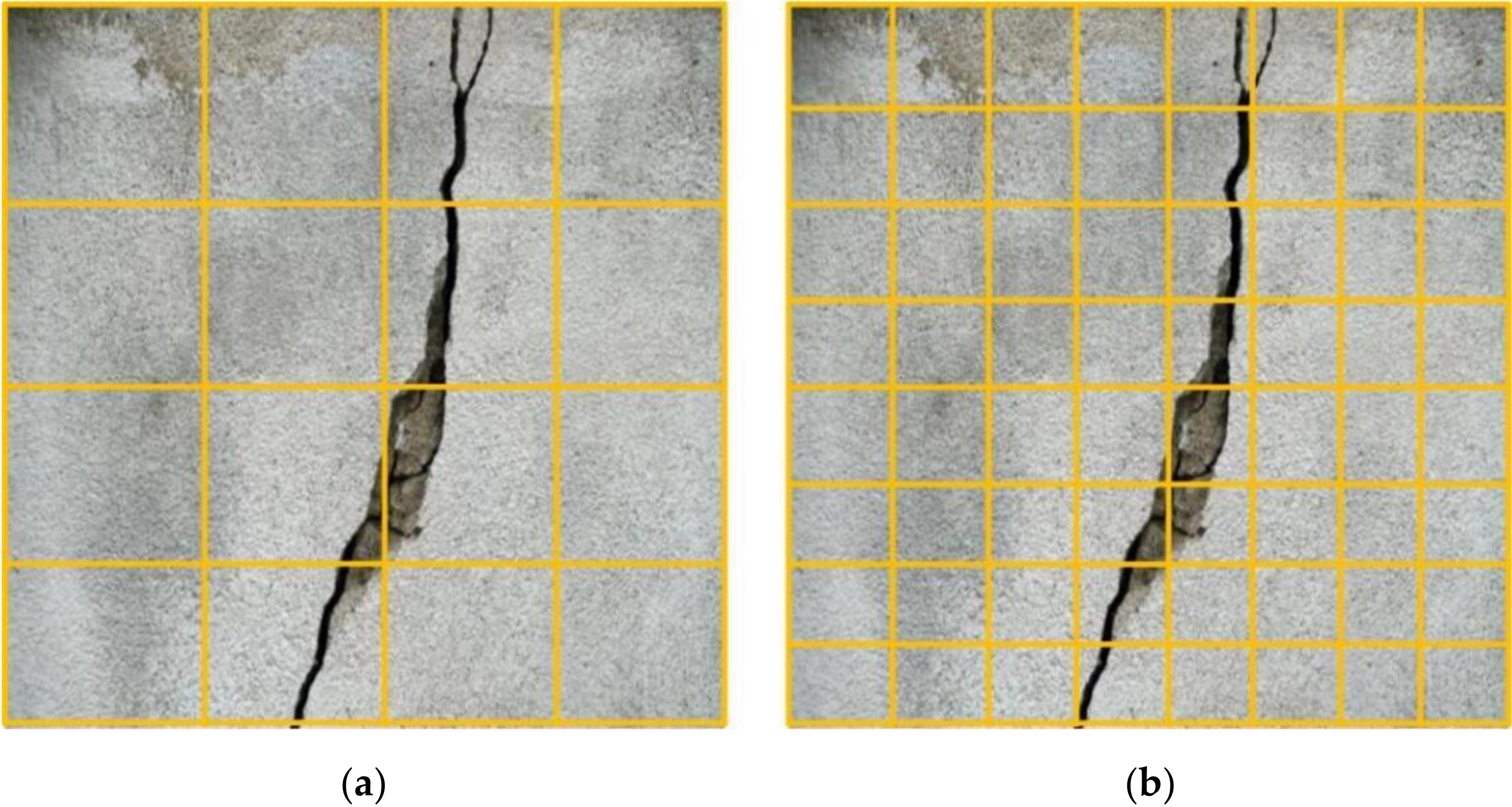
Figure 1 shows the concrete crack image with pixel. We use the grid size with to cover the concrete crack image, and then calculate the number of squares with fire pixels in the grid. We obtain the number of squares , as shown in Table 1.
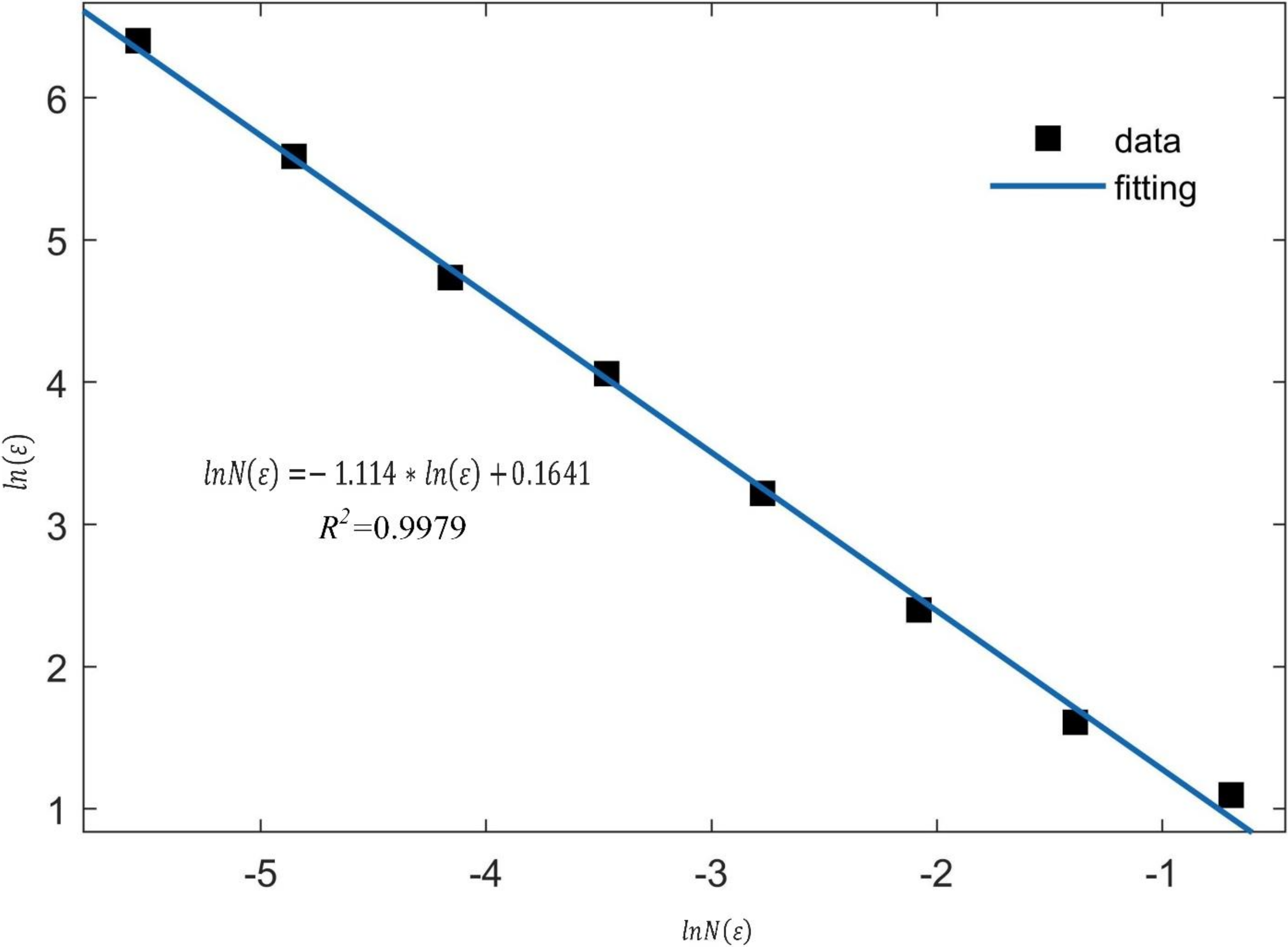
According to Table 1, the fitting of and in linear coordinate system is established, as shown in Figure 2.
It is clearly visible that the relationship between and is linear function, and the fitting degree is 0.9979. It illustrates that the linear fitting of box dimension is suitable for quantitative characterization of fire distribution characteristics. According to the linear fitting function, the fractal dimensional of different grid size is −1.114.
According to the above concept of global fractal dimension, we use the local fractal dimension to conduct the initial concrete crack detection. An image with is selected and the center point of any pixel is determined. We select the region L and its center point is . The fractal dimensions of all pixels are obtained according to the fractal dimension of region L. The fractal dimensions will be compared with the threshold . If , the pixel contains a crack, or else the pixel does not contain a crack. Thereby, we can achieve the initial concrete crack detection.
2.2. U-Net Network Model
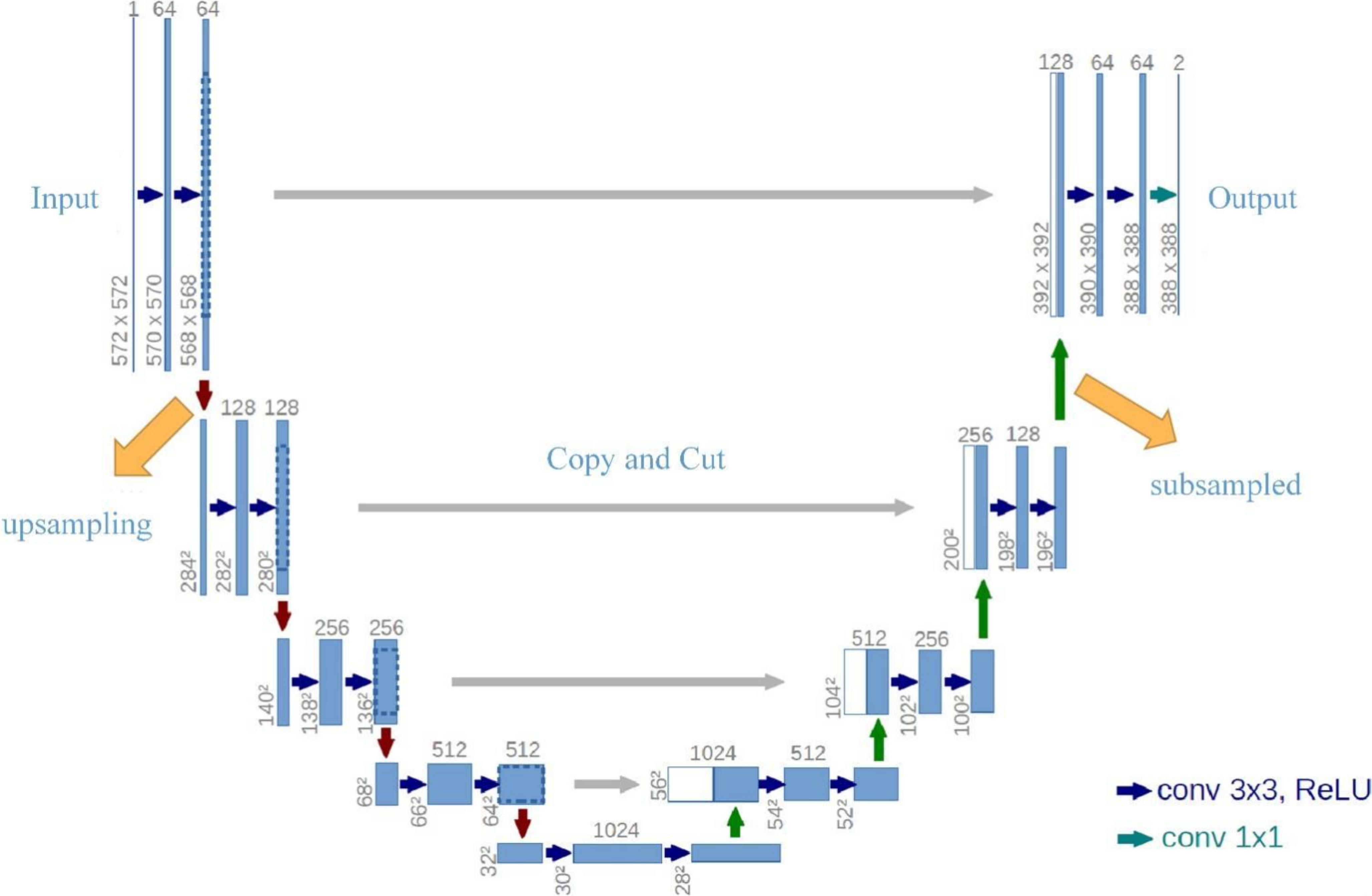
In the field of image segmentation, U-Net network model has been studied by many researchers. Comparing with FCN network, U-Net network structure includes contracting path and expanding path, which is completely symmetric. The role of the contracting path is to extract features, while the role of the expanding path is to carry out upsampling operation. For each upsampling operation, the same scale fusion is carried out with the number of channels corresponding to the feature extraction. In the section of skip connection, U-Net adopted the concatenation. U-Net network model was mainly used to the medical image segmentation. Most medical images mainly present human skeleton information, and the skeleton structure information has the characteristic of line distribution. Concrete cracking also has linear characteristics that are very similar with medical images. Therefore, we use the U-Net network to conduct the semantic segmentation of concrete crack images. The structure of U-Net network is described as Figure 3.
In the U-Net network, there are about 20 convolutional layers, four subsampled operations, and four upsampling operations. U-Net network model has better performance in semantic segmentation. This network model not only used in the field of medical image segmentation, but also in the field of concrete crack image semantic segmentation.
2.3. UHK-Net Network Model
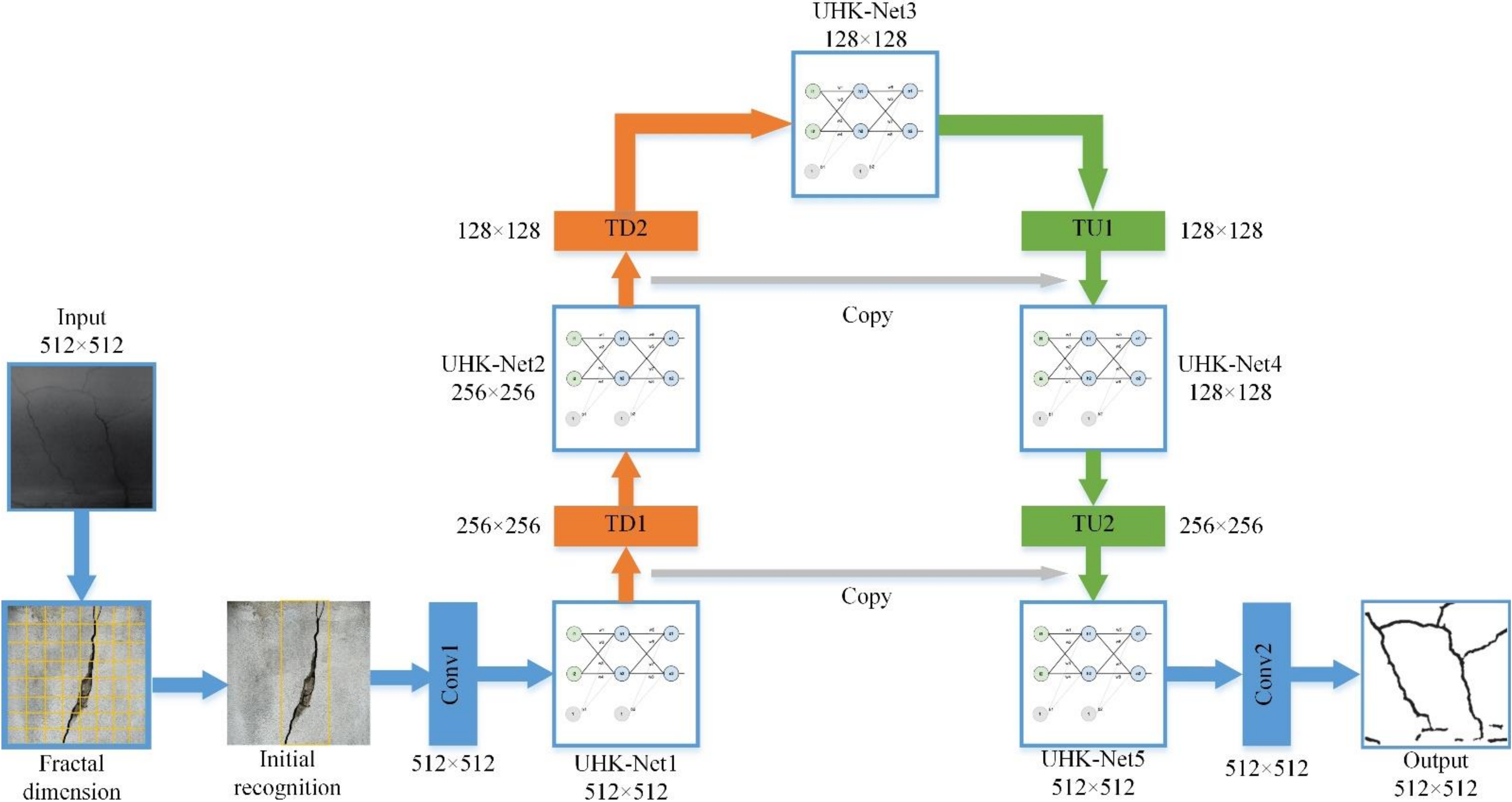
In this paper, we propose a UHK-Net network model, as described in Figure 4. This network structure also includes contracting path and expanding path, as described in Section 2.2.
In the U-Net network model, the feature extraction block replaces the ordinary convolution layer. The feature extraction block is used to extract features from two inputs, as described in Equation (5).
where and are the initial feature extraction of over-exposed and under-exposed input.
The structure of feature extraction block includes two convolutional layers, and it uses PReLU activation function. The first convolutional layer has 256 convolution kernels, and their size is . This layer is used for the initial feature extraction. The second convolutional layer has 64 convolution kernels, and their size is . This layer can be understood as further integration of features between channels. Thereby, the feature extraction block can reduce the number of subsampled operations.
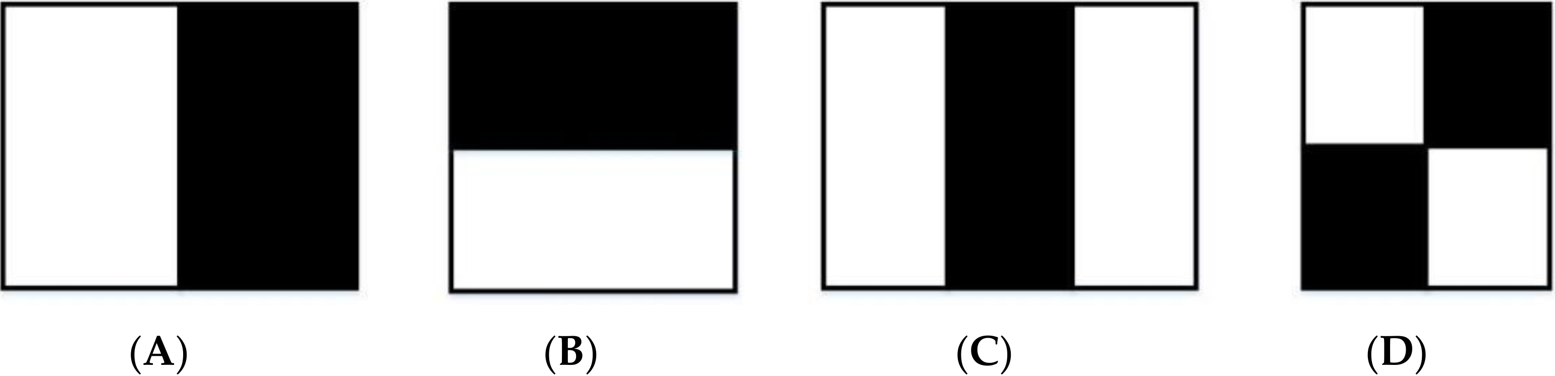
In addition to the feature extraction block, the proposed UHK-Net network model also includes upward transition layer and downward transition layer. In view of the complicated background of concrete cracks, we adopt Haar-like feature extraction algorithm to extract edge and contour feature of concrete cracks. Haar-like define four basic feature structure, as shown in Figure 5A–D.
These four basic feature structures are considered as four windows. These windows conduct the slide with one step, and traverse the image. When one iteration is done, the window will be enlarged proportionally in width or length. Repeat the previous steps, until it enlarges the last scale. Assume the maximum enlargement times of the width and height are and respectively, as described in Equation (6).
where and are the height of the image, and are the initial width and height of the Haar window.
The process of the Haar-like feature extraction is to use the Haar window to slide in the image. When sliding to a position, one of the dimensions of the Haar feature is obtained by the subtraction between the sums of the pixels of the white position covered by the window with the black position. For the window C, in order to obtain the same number of pixels, the sum of the pixels in the black area should be multiplied by weight 2.
Haar-like algorithm has only black and white rectangular feature templates which coincide with actual concrete crack features. We use the edge and linear attribute feature of Haar-like algorithm to extract features from input images. There are two down-transition layers and two up-transition layers in the network. The size of the last output layer is the same as the input image. In the process of upsampling, the output features of each block are not only transferred to the next layer, but also are used for feature fusion in the process of symmetric subsampled, so as to obtain better prediction results and feature extraction effect.
Table 2 shows the parameters of each layer. From Table 2, it is visible that different layer has different output size, operation type, operation size, and depth. For the Convl layer, the operation type is conv and operation size is 3 × 3. However, for the TD1 layer, there is only one output size, but two operation types which are conv and pool.
In the process of calculation of Haar eigenvalues, the rectangular feature region will always be traversed repeatedly every time. As a result, it takes a lot of time. The integral graph can be used to quickly calculate the rectangular features. The main idea of this method is to sum the pixel values of the rectangular region formed between the initial pixel and its neighboring pixel. In other words, the original images are converted into an integral graph. Therefore, the Haar eigenvalues can be obtained by calculating the values of the four corners in the integral graph when conduct the sum of pixels in a rectangular region. The whole process only needs to traverse the image once, and the time complexity of computing features is constant, so the computing efficiency will be greatly improved.
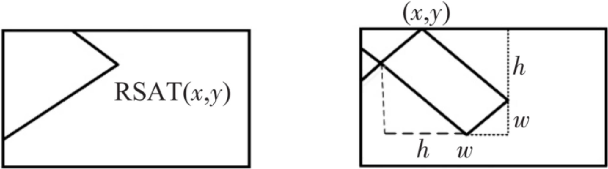
After constructing the integrogram, the sum of the pixel values of any rectangular region in the image can be quickly obtained by addition and subtraction. In order to reduce the computational expense and improve the performance of the algorithm, two kinds of integral images are introduced to calculate features quickly. For the horizontal rectangle, the integral formula of the sum of image pixels is constructed, as described in Equation (7).
where SAT (x,y) is the sum of pixels in a rectangular integral diagram from upper left (0,0) to lower right (x,y). is the pixel coordinates
For a rectangle with an inclination of 45°, as shown in Figure 6, the integral formula of the sum of image pixels is shown in Equation (8).
3. Performance Evaluation Results
3.1. Model Preparation
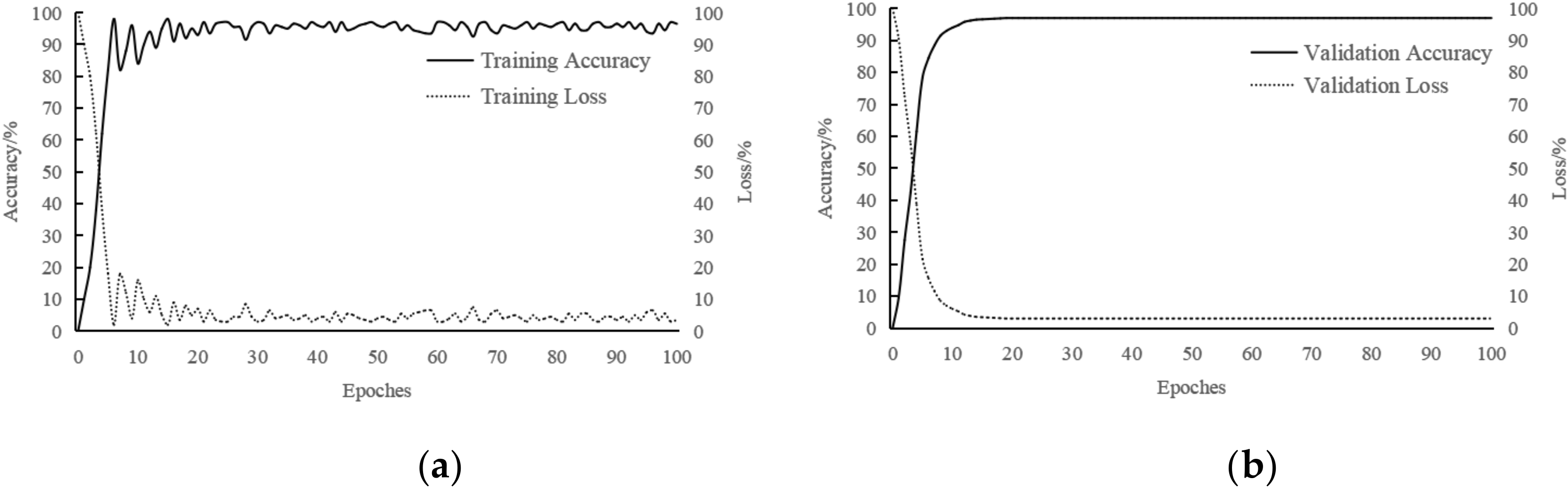
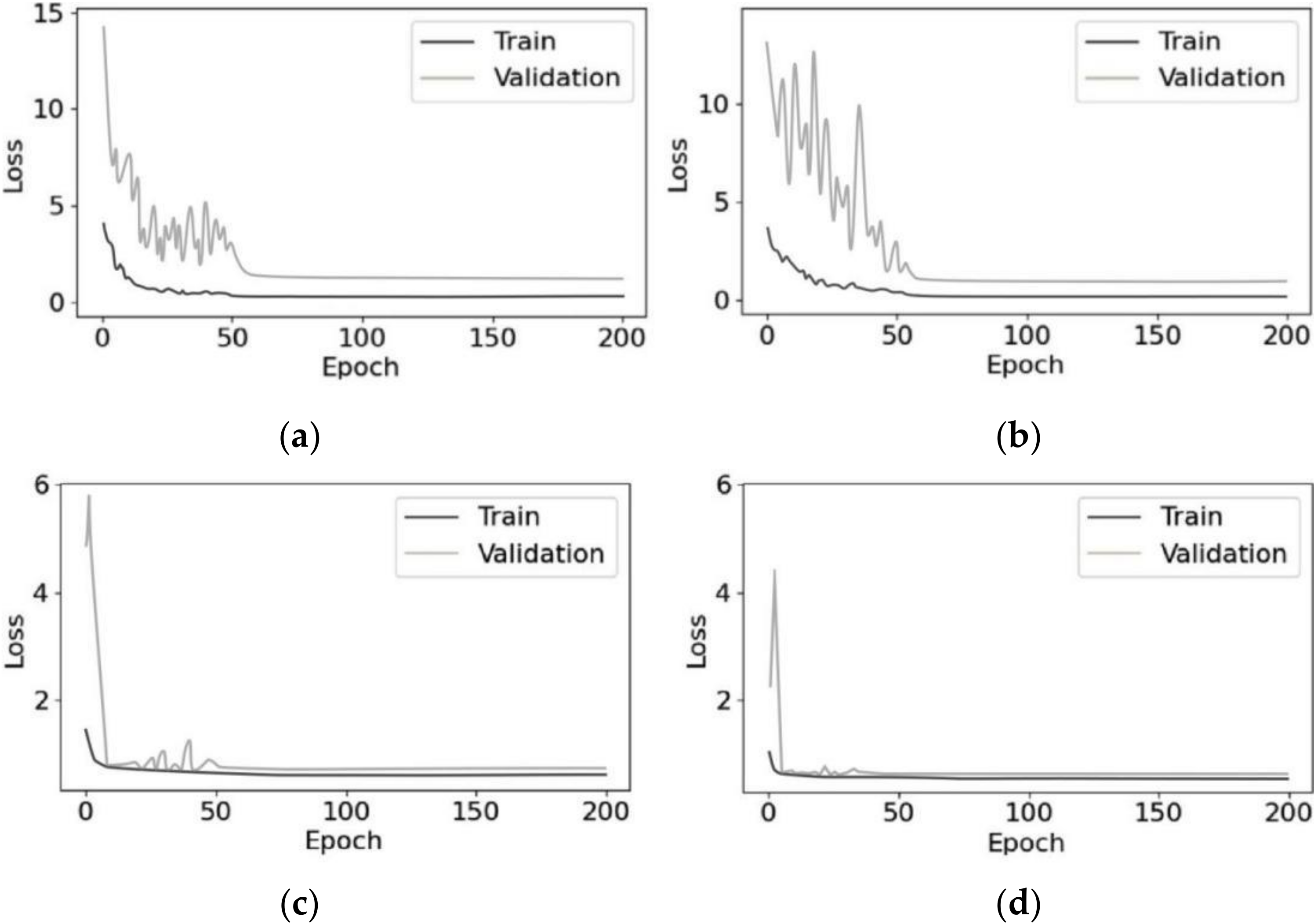
In order to evaluate the performance of the proposed method, we conduct the segmentation of concrete cracks under complex background. First, we use the fractal dimension to conduct the initial recognition of concrete cracks, and obtain some images which includes cracks. Then we use the UHK-Net network model to conduct the segmentation of concrete cracks. In order to train the UHK-Net network model, we used the CCD industrial camera (Basler aca1300-30 gm) mounted on the drone to collect 1000 original images, most of which are crack pictures with complex backgrounds, and each image is different due to different photographing conditions. The size of the collected original images is 4896 3672 pixels. They are divided into 512 512 sub-images in steps of 248, and 1000 original images are divided into 46,000 sub-images. Simultaneously, we take some pictures of concrete crack and collect some crack images on the internet. The final data set contained 51,000 images. 48,000 images are used for training and 3000 for testing and verifying the effectiveness of the network. We train the UHK-Net network model with batch size of 128 on a Nvidia GTX 2080ti GPU, and use the test dataset to verify the training results, the accuracy and loss of training and validation are obtained, as shown in Figure 7.
From Figure 7a, it is clearly visible that the convergence rate of UHK-Net training loss rate is very fast. Although, there are severe fluctuations in the first 20 traversals, the overall training accuracy tend to a stable value after 20 traversals. Therefore, the UHK-Net model training is accomplished after 20 traversals. Similarly, training loss shows the opposite process. Figure 7b shows that the validation loss curve has been decreasing, and it begins to converge rapidly from the 10th traversal. The validation loss tends to a stable value after the 20th iteration, and the validation accuracy tends to 97%.
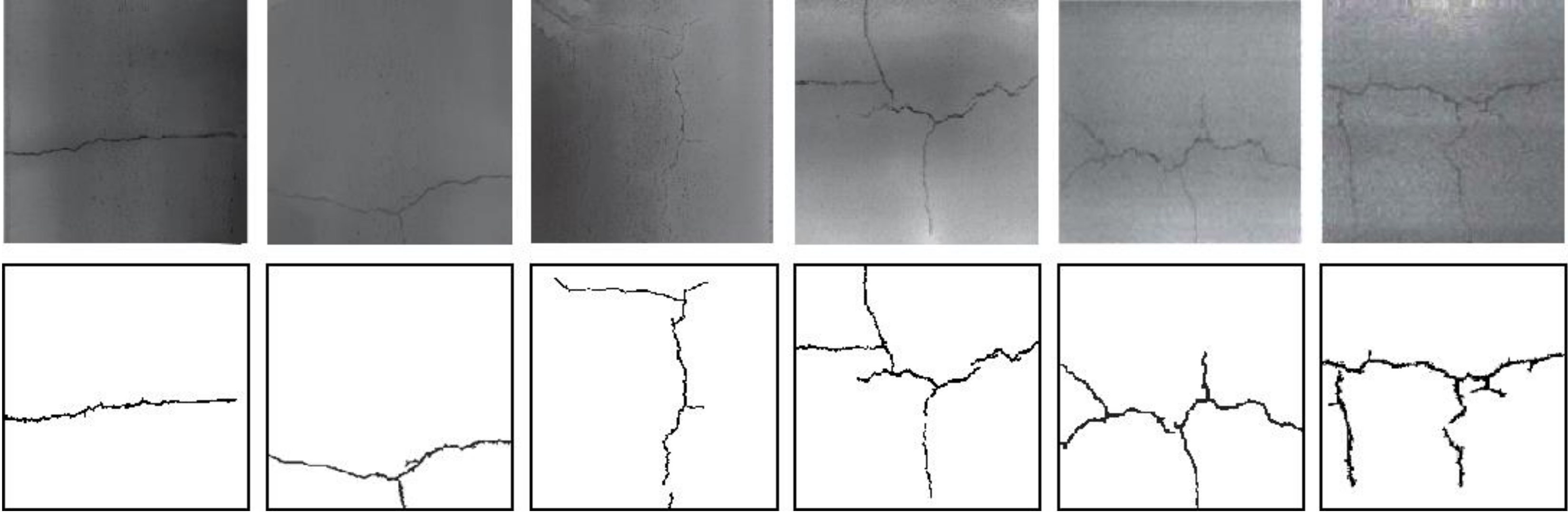
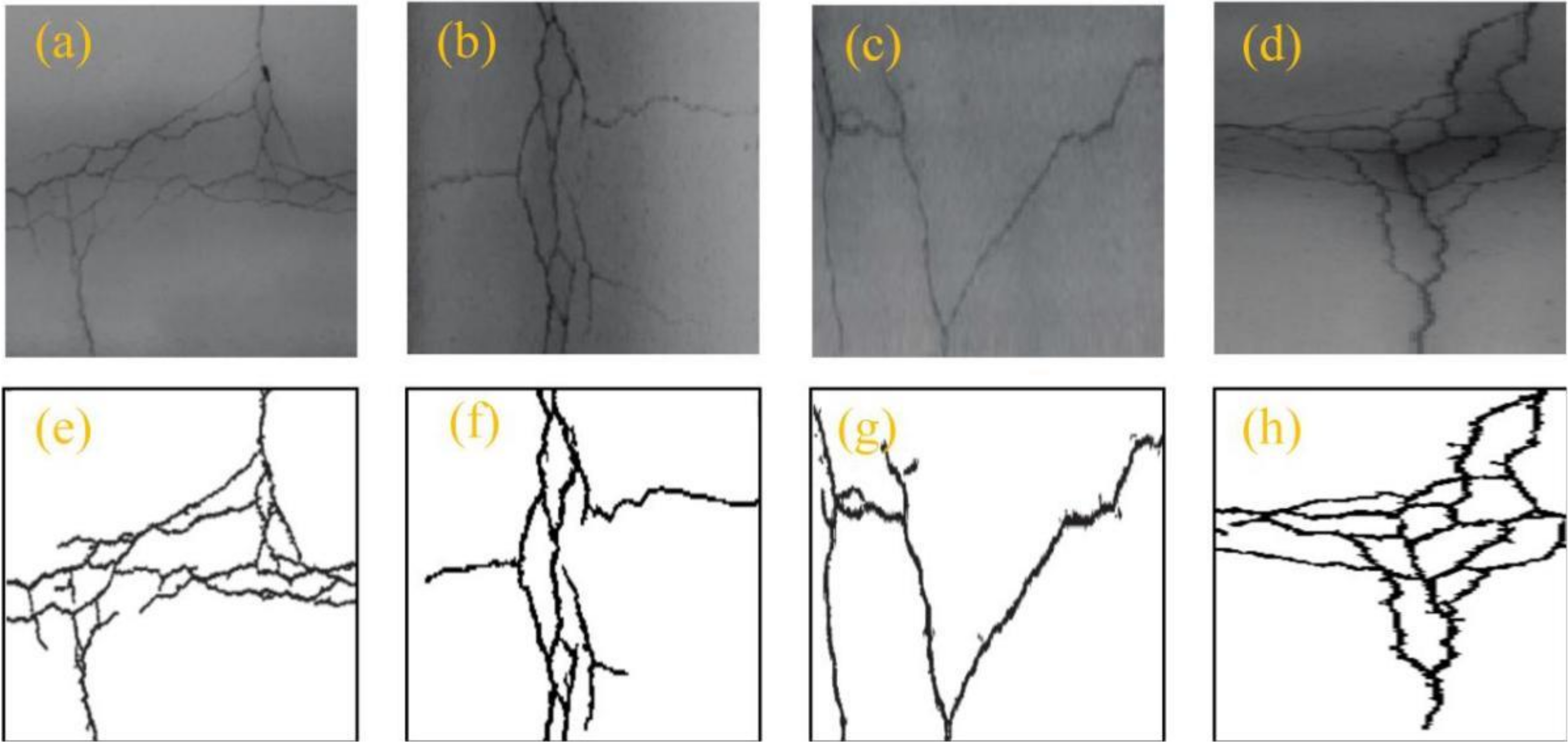
The first and second images in Figure 8 include simple cracks. Even in the dark light, the overall segmentation effectiveness is very clear and complete. There is a little noise around the cracked skeleton. In view of the third image, the segmentation effectiveness is also good. However, there are some noises in the middle of crack and the segmented crack skeleton is discontinuity in the lower part because of the dark light. Although the lighting in the fourth image is uneven, UHK-net can completely extract the concrete crack skeleton, which includes small and branching cracks in the middle area and the discontinuous region of the right side. However, there are many discontinuities in the middle and lower part of the crack. The reason for this phenomenon is that difference brightness in the two regions. For the fifth concrete crack image, the overall crack can be extracted clearly, and there is no noise. However, the annular crack in the middle area of the crack cannot be identified. The reason for this result is that the annular crack is too small and its color is dark. For the last image, the overall extraction effectiveness of the concrete crack is similar with the fourth image. However, there are small gaps in the upper left and lower right of the crack skeleton, and the bottom of the crack is not extracted. Because the bottom of the concrete crack image contains shading. According to the above analysis, UHK-Net network model has the performance of segmentation of concrete crack image which includes shading, especially suitable for the extraction of reticulation cracks. In order to verify the advantage of the UHK-Net network model, we compare the UHK-Net network with U-Net, FCN, and YOLO v5 network models. The training and validation loss curves obtained by different networks are obtained, as shown in Figure 9.
From Figure 9a,b, it is clearly visible that the fluctuation of loss curves of U-Net and FCN are severe, and the convergence is slow. The validation loss of the FCN model fluctuates greatly in the first 50 traversals. However, the fluctuation of verification loss of U-Net is not as large as that of FCN network model, but it still fluctuates greatly. Both of these two networks tend to stabilize after 50 iterations. Simultaneously, the training and validation loss of U-Net network are similar to FCN after they are stable. Comparing with YOLO v5 and UHK-Net, the convergence rate of U-Net and FCN network model are slow. The training and validation loss of YOLO v5 tend to a minor fluctuation after the 10th iteration, and then there is a large fluctuation until the 50th iteration. After 50 iterations, the YOLO v5 network model tend to stable, it is similar to the UHK-Net network model. However, the convergence rate of the UHK-Net is faster than the YOLO v5 network. It illustrates that the computational complexity of UHK-Net is lower than the other three methods. Furthermore, the training and validation loss of the UHK-Net is lower than the other three networks.
3.2. Evaluation of Computational Complexity of Different Methods
In order to evaluate the computational complexity, we use the U-Net, FCN, YOLO v5, and UHK-Net networks to train and segment 51,000 concrete cracks images, the training and segmentation time are obtained, as shown in Table 3.
From Table 3, it is clearly visible that the training time of U-Net is the longest. The training time of FCN is greater than YOLO v5 and UHK-Net networks. By the same token, the segmentation time of U-Net is greater than the other three networks. Nevertheless, training and segmentation time of YOLO v5 is similar to that of the UHK-Net network. The training time of the UHK-Net network is less than the other three networks. Additionally, the segmentation time of UHK-Net network is less than U-Net and FCN, and almost the same as UHK-Net. Thereby, the computational complexity of UHK-Net network is similar to that of YOLOv5, and they are lower than U-Net and FCN.
3.3. Comparison Analysis Based on the Visualization
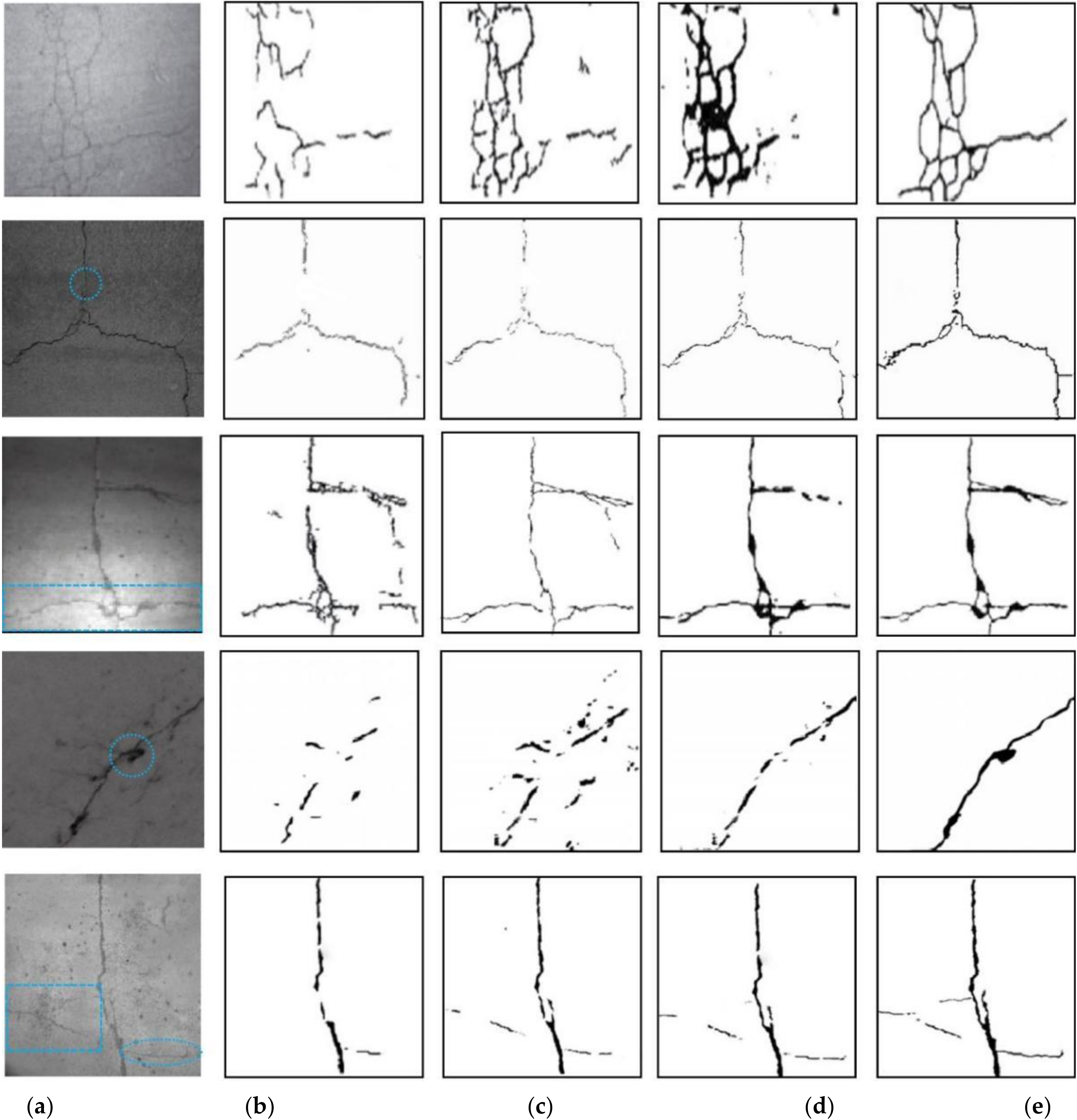
Five concrete crack images taken under dim light are used to conduct the comparison between FCN, U-Net, YOLO v5, and proposed method in the field of crack segmentation. These four methods segment the concrete crack, as shown in Figure 10.
Figure 10a shows that the first crack image is complex, and there are many fine cracks. It is difficult to extract the fine cracks by the FCN network, as shown in the first row of Figure 10b. Although U-Net can extract part of crack skeleton, there are many crack noise points. For example, the top right corner of the first row of Figure 10c shows that the non crack pixel is regarded as crack. YOLO v5 over-segments the crack skeleton, results in the weakening of the extracted linear features, which makes some small cracks join together into a black shadow. Simultaneously, this network ignores the linear cracks at the bottom right of the first row of Figure 10d. From the first row of Figure 10e, it is clearly visible that the U-NET network can accurately segment all cracks. It not only ensures the continuity and integrity of the crack skeletons, but also clearly extracts the linear features of the cracks. The circle in the second row of Figure 10a shows that there is a very fine small annular crack. The FCN, U-Net, and YOLO v5 do not have the ability to segment it. Additionally, the crack skeleton extracted by the FCN and U-Net exist many breakages, as shown in the second row of Figure 10b,c. Although the segmentation effectiveness of YOLO v5 is superior to the FCN and U-Net, it still failure to segment part fine cracks. The second row of Figure 10e shows that the segmentation effectiveness of proposed method is superior to other three networks. The third row of Figure 10a shows that the third crack image has uneven brightness distribution. The extraction effect of FCN is not very good, and there are a few ruptures and noise points. Although U-Net has good performance in removing noise, there are also a few noise points. YOLO v5 has over-segmentation in the bright region and under-segmentation in the shadow region, as shown in the third row of Figure 10d. The proposed method can clearly segment the mesh cracks. The fourth image take under dark light and there is a small sunken, as shown in the circle of the fourth row of Figure 10a. Although the crack shape in this image is simple. The FCN and U-Net networks have bad segmentation results, and can hardly extract the crack skeleton correctly. The fourth row of Figure 10b,c shows that there are a lot of noise points by the FCN and U-Net segmentation results. YOLO v5 can roughly segment the crack skeleton and eliminate most of the noises, but fails to segment the sunken, as shown in the fourth row of Figure 10d. The proposed method not only segments the crack skeleton but also extract the sunken, as shown in the fourth row of Figure 10e. For the fifth image, there are a lot of splashes and a few of fine cracks, as shown in the rectangle and ellipse of the fifth row of Figure 10a. This image brightness is better than the other four images. Therefore, the cracks in the fifth image can be approximately segmented by the four networks. FCN almost does not has the ability to segment the fine cracks, and there are a few ruptures in the extracted cracks. The performance of U-NET is superior to the FCN, but it cannot segment the fine cracks. Although the performance of YOLO v5 is a little better than U-NET and it can segment more crack details than U-NET, it still missed a few fine cracks, as shown in the fifth row of Figure 10d. The proposed method not only ensures the integrity of the main crack skeleton, but also achieves the segmentation of the fine cracks. According to the above analysis, the proposed method is not only suitable for image crack segmentation under dark light, but also for image crack segmentation under non-uniform brightness. Simultaneously, the segmented crack by the proposed method is almost the same as the actual crack, as shown in the Figure 10e.
3.4. Quantitative Evaluation of Different Methods
In the process of concrete crack recognition, if an image pixel is concrete crack and it is identified as concrete crack, then it is counted as a true positive (TP). If it is identified as non-crack, it is then counted as false negative (FN). If the correct hypothesis of an image pixel is non-crack and it is identified as non-crack, it is then counted as true negative (TN). If it is identified as a crack, then it is counted as FP. For the image semantic segmentation, the use of the tri-partite measures of pixel accuracy (PA), mean pixel accuracy (MPA), and mean intersection over union (MIoU) is an effective way for assessing the performance of concrete crack recognition. PA is the proportion of exact pixels to total pixels.
MPA is first calculate the proportion of correctly classified pixels in each class, and then calculate the average of all classes.
MIoU is the ratio of the intersection and union of the two sets of true and predicted value.
According to the recognition results, we can obtain the PA, MPA, and MIoU of the proposed method, FCN, U-Net, and YOLO v5 network model, as shown in Table 4.
From Table 3, it is clearly visible that the PA of the four network models is greater than 90%; among those models, the proposed method even greater than 97%. The YOLO v5 is similar with proposed method. The PA obtained by FCN is lowest. The MPA of the FCN network is less than 90%, and other three networks are similar and all greater than 90%. For the MIoU, only the proposed method is greater than 90%, the other three networks are lower than 90%. According to the comparison of different methods in the four indicators, the performance of the proposed method is superior to the other three methods in the field of segmentation of concrete crack images.
4. Case Study
In this section, we use the proposed method to conduct the segmentation of some concrete crack images, which include simple mesh cracks and complex mesh cracks. For a large area (building wall), we first divide the image into several sections according to the image size. Second, the fractal dimension is used to conduct the initial detection of every sections. The section images which include cracks can be determined and other sections without cracks will be deleted, as shown in Figure 11.
Therefore, the proposed method mainly includes two steps: initial detection based on fractal dimension and fine segmentation based on UHK-Net network, as shown in Figure 12.
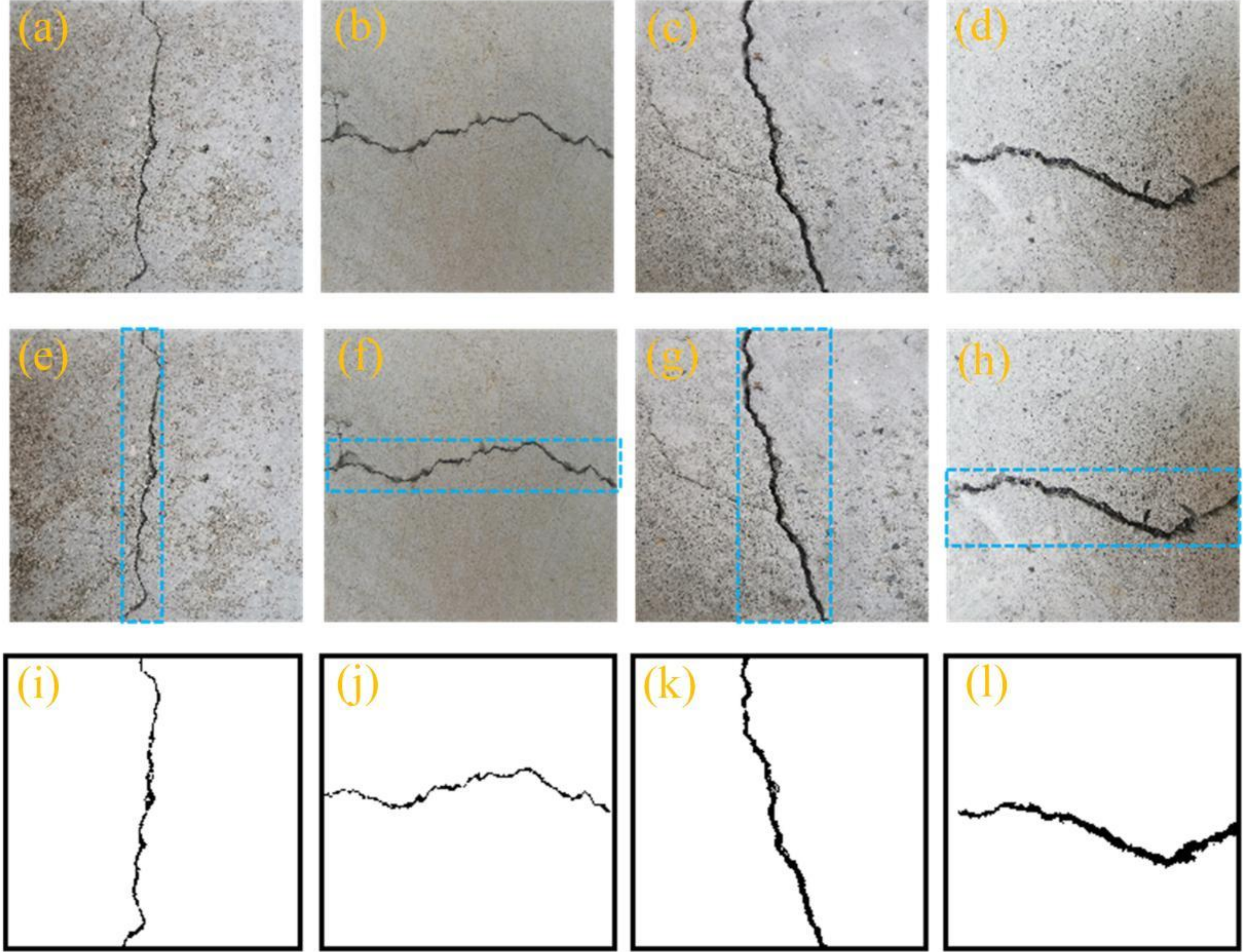
In order to verify the applicability of the proposed method, the simple and complex crack images are used for the segmentation by the proposed method. Simultaneously, the brightness of different crack images is also different. For example, some crack images are brighter, some are darker, as shown in Figure 13 and Figure 14.
Figure 13a–d show that the crack images taken under dark light and the crack brightness are not uneven. Figure 13a shows that the first crack image is very simple, and there are two main cracks. The proposed method accurately extracts the cracks, as shown in Figure 13e. The second crack image is more complex than the first, and the brightness of the crack area is dark. The complex cracks are accurately segmented by the proposed method, as shown in Figure 13f. For the third crack image, the crack is wide and obvious. Therefore, it is easy to segment the crack by the proposed method. Figure 13d shows that the brightness of the crack is similar to that of the surrounding concrete, and the crack is not clear. The cracks are still segmented by the proposed method, as shown in Figure 13h.
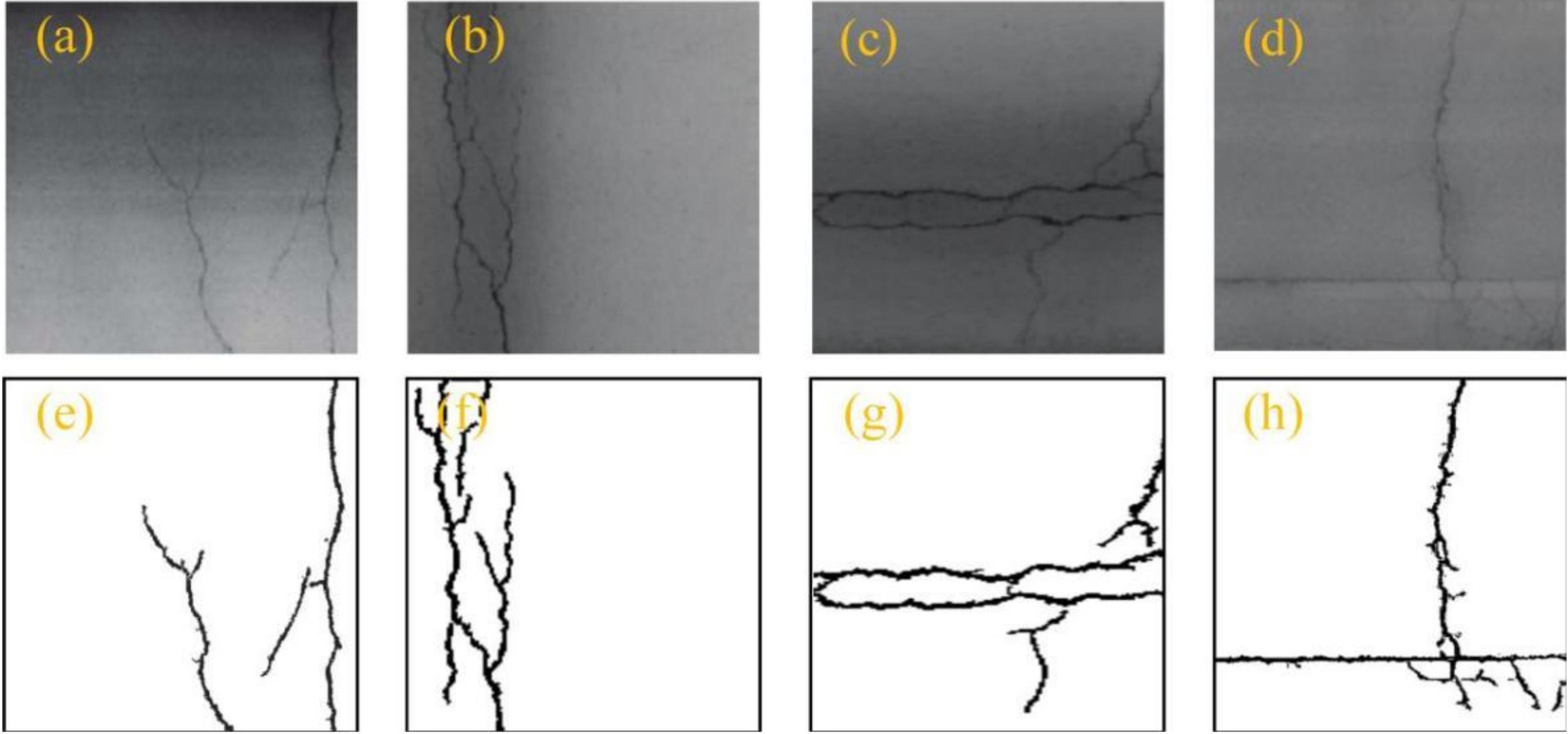
From Figure 14a–d, it is visible that the crack images are more complex than the crack in Figure 13. Especially, the first and fourth crack images contain many mesh cracks, as shown in Figure 14a,d. The proposed method only segments overall crack skeleton but also extracts small cracks. For example, the first crack image is a mesh shape, and there are fractures between the cracks. The proposed method segments all cracks, which includes fractured cracks, as shown in Figure 14e. The second and third crack images are simpler than the first and fourth, and the crack morphology is more obvious. Therefore, the proposed method can easily segment the second and third cracks image, as shown in Figure 14f,g. The fourth crack image is very clear, and the crack width is larger than the other three crack images. Although the luminance of the middle region in fourth image is low, the proposed method can accurately segment the cracks, as shown in Figure 14h.
5. Conclusions
This paper studied the segmentation of concrete cracks by using the fractal dimension and UHK-Net network. We first use the fractal dimension to identify the pixels of concrete cracks. Then, the UHK-Net is constructed based on the feature extraction of contracting path and expanding path. Ultimately, the performance of the UHK-Net network is compared with FCN, U-Net, and YOLO v5 network models.
(1) The UHK-Net network can be rapidly converged. The training time of UHK-Net only is about 7 h. It is similar to that of YOLO v5, and is shorter than that of other two networks.
(2) The computation complexity of the proposed method is lower than other methods. The segmentation time of the proposed method is less than 1 s.
(3) The PA, MPA, and MIoU of all of the proposed methods is greater than 90%, and the segmentation performance of the proposed method is superior to other three methods.
The proposed method can only segment the concrete cracks. However, the size of the concrete cracks cannot be measured. In the future, we will focus on the semantic segmentation of concrete cracks and determine the size of concrete cracks.
Author Contributions
Conceptualization, writing—original draft preparation, funding acquisition, Q.A.; Conceptualization, methodology, data curation, writing—review and editing, funding acquisition, X.C.; Software, resources, data curation, H.W.; Validation, H.Y. and Y.Y.; Formal analysis, investigation, W.H. and L.W. All authors have read and agreed to the published version of the manuscript.
Funding
This research was funded by the technology project of Hubei Province Safety Production special fund (Program SN: SJZX 20211006) and the CRSRI Open Research Program (Program SNCKWV2019758/KY).
Institutional Review Board Statement
Not applicable.
Informed Consent Statement
Not applicable.
Data Availability Statement
The data used to support the findings of this study are available from the corresponding author upon request.
Acknowledgments
The authors would like to thank all the anonymous referees for their constructive comments and suggestions.
Conflicts of Interest
There is no conflict of interest.
References
- Huang, J.; Li, W.; Huang, D.; Wang, L.; Chen, E.; Wu, C.; Wang, B.; Deng, H.; Tang, S.; Shi, Y.; et al. Fractal Analysis on Pore Structure and Hydration of Magnesium Oxysulfate Cements by First Principle, Thermodynamic and Microstructure-Based Methods. Fractal Fract. 2021, 5, 164. [Google Scholar] [CrossRef]
- Wang, L.; Lu, X.; Liu, L.; Xiao, J.; Zhang, G.; Guo, F.; Li, L. Influence of MgO on the Hydration and Shrinkage Behavior of Low Heat Portland Cement-Based Materials via Pore Structural and Fractal Analysis. Fractal Fract. 2022, 6, 40. [Google Scholar] [CrossRef]
- Wang, L.; Luo, R.Y.; Zhang, W.; Jin, M.M.; Tang, S.W. Effects of Fineness and Content of Phosphorus Slag on Cement Hydration, Permeability, Pore Structure and Fractal Dimension of Concrete. Fractals 2021, 29, 2140004. [Google Scholar] [CrossRef]
- Zhu, H.C.; Tong, Y.J.; Ji, T.; Peng, W.W.; Chen, M.; Xiao, T.Q. Elimination technology of noise introduced by top-up injection in synchrotron radiation infrared beamline. J. Infrared Millim. Waves 2018, 37, 251–257. [Google Scholar]
- Su, T.-C.; Yang, M.-D.; Wu, T.-C.; Lin, J.-Y. Morphological segmentation based on edge detection for sewer pipe defects on CCTV images. Expert Syst. Appl. 2011, 38, 13094–13114. [Google Scholar] [CrossRef]
- Yang, S.; Shao, L.T.; Guo, X.X.; Liu, X.; Zhao, B.Y. A Crack Segmentation Approach Using the Combination of Gray Thresholds and Fractal Feature. Adv. Mater. Res. 2012, 487, 622–626. [Google Scholar] [CrossRef]
- Wang, G.; Zhang, X.; Han, Y.; Wang, H.; Li, Y. Automatic multi-region segmentation of intracoronary optical coherence tomography images based on neutrosophic theory. Sheng Wu Yi Xue Gong Cheng Xue Za Zhi = J. Biomed. Eng. = Shengwu Yixue Gongchengxue Zazhi 2019, 36, 59–67. [Google Scholar]
- Lin, L.K.; Wang, S.Y.; Tang, Z.X. Point target detection in infrared over-sampling scanning images using deep convolutional neural networks. J. Infrared Millim. Waves 2018, 7, 219–226. [Google Scholar]
- Wu, Q.P.; Wu, C.M. A fast and robust clustering segmentation algorithm for kernel space graphics. CAAI Trans. Intell. Syst. 2019, 14, 804–811. [Google Scholar]
- Adhikari, R.S.; Moselhi, O.; Bagchi, A. Image-based retrieval of concrete crack properties for bridge inspection. Autom. Constr. 2014, 39, 180–194. [Google Scholar] [CrossRef]
- Nhat-Duc, H.; Nguyen, Q.-L.; Tran, V.-D. Automatic recognition of asphalt pavement cracks using metaheuristic optimized edge detection algorithms and convolution neural network. Autom. Constr. 2018, 94, 203–213. [Google Scholar] [CrossRef]
- Arena, A.; Piane, C.D.; Sarout, J. A new computational approach to cracks quantification from 2D image analysis: Application to micro-cracks description in rocks. Comput. Geosci. 2014, 66, 106–120. [Google Scholar] [CrossRef]
- Li, L.; Wang, Q.; Zhang, G.K.; Shi, L.; Dong, J.; Jia, P. A method of detecting the cracks of concrete undergo high-temperature. Constr. Build. Mater. 2018, 162, 345–358. [Google Scholar] [CrossRef]
- Chen, X.; Li, J.; Huang, S.; Cui, H.; Liu, P.; Sun, Q. An Automatic Concrete Crack-Detection Method Fusing Point Clouds and Images Based on Improved Otsu’s Algorithm. Sensors 2021, 21, 1581. [Google Scholar] [CrossRef]
- Safaei, N.; Smadi, O.; Safaei, B.; Masoud, A. Efficient Road Crack Detection Based on an Adaptive Pixel-Level Segmentation Algorithm. Transp. Res. Rec. J. Transp. Res. Board 2021, 2675, 370–381. [Google Scholar] [CrossRef]
- Krawczuk, M.; Ostachowicz, W.M. Spectral Finite Element and Genetic Algorithm for Crack Detection in Cantilever Rod. Key Eng. Mater. 2001, 204, 241–250. [Google Scholar] [CrossRef]
- Ren, Y.; Huang, J.; Hong, Z.; Lu, W.; Yin, J.; Zou, L.; Shen, X. Image-based concrete crack detection in tunnels using deep fully convolutional networks. Constr. Build. Mater. 2020, 234, 117367. [Google Scholar] [CrossRef]
- Mohan, A.; Poobal, S. Crack detection using image processing: A critical review and analysis. Alex. Eng. J. 2018, 57, 787–798. [Google Scholar] [CrossRef]
- Dorafshan, S.; Thomas, R.J.; Maguire, M. Comparison of deep convolutional neural networks and edge detectors for image-based crack detection in concrete. Constr. Build. Mater. 2018, 186, 1031–1045. [Google Scholar] [CrossRef]
- Zhang, A.; Wang, K.C.; Li, B.; Yang, E.; Dai, X.; Peng, Y.; Fei, Y.; Liu, Y.; Li, J.Q.; Chen, C. Automated pixel-level pavement crack detectionon 3D asphalt surfaces using a deep-learning network. Comput.-Aided Civ. Infrastruct. Eng. 2017, 32, 805–819. [Google Scholar] [CrossRef]
- Song, L.; Wang, X. Faster region convolutional neural net-work for automated pavement distress detection. Road Mater. Pavement Des. 2019, 21, 1–19. [Google Scholar]
- Mandal, V.; Uong, L.; Adu-Gymfi, Y. Automated road crack detection using deep convolutional neural networks. In Proceedings of the 2018 IEEE International Conference on Big Data (Big Data), Seattle, WA, USA, 10–13 December 2018; pp. 5212–5215. [Google Scholar]
- Cha, Y.; Choi, W.; Büyüköztürk, O. Deep learning-based crack damage detection using convolutional neural networks. Comput. Civ. Infrastruct. Eng. 2017, 32, 361–378. [Google Scholar] [CrossRef]
- Gopalakrishnan, K.; Khaitan, S.K.; Choudhary, A.; Agrawal, A. Deep Convolutional Neural Networks with transfer learning for computer vision-based data-driven pavement distress detection. Constr. Build. Mater. 2017, 157, 322–330. [Google Scholar] [CrossRef]
- Yang, F.; Zhang, L.; Yu, S.; Prokhorov, D.; Mei, X.; Ling, H. Feature Pyramid and Hierarchical Boosting Network for Pavement Crack Detection. arXiv 2019, arXiv:1901.06340. [Google Scholar] [CrossRef] [Green Version]
- Elkashef, M.; Williams, R.C.; Cochran, E. Investigation of fatigue and thermal cracking behavior of rejuvenated reclaimed asphalt pavement binders and mixtures. Int. J. Fatigue 2018, 108, 90–95. [Google Scholar] [CrossRef]
- Farabet, C.; Couprie, C.; Najman, L.; LeCun, Y. Learning Hierarchical Features for Scene Labeling. IEEE Trans. Pattern Anal. Mach. Intell. 2012, 35, 1915–1929. [Google Scholar] [CrossRef] [Green Version]
- Long, J.; Shelhamer, E.; Darrell, T. Fully convolutional networks for semantic segmentation. In Proceedings of the IEEE Conference on Computer Vision and Pattern Recognition, Boston, MA, USA, 7–12 June 2015; pp. 3431–3440. [Google Scholar] [CrossRef] [Green Version]
- Yang, X.; Li, H.; Yu, Y.; Luo, X.; Huang, T.; Yang, X. Automatic Pixel-Level Crack Detection and Measurement Using Fully Convolutional Network. Comput.-Aided Civil Infrastruct. Eng. 2018, 33, 1090–1109. [Google Scholar] [CrossRef]
- Dung, C.V.; Anh, L.D. Autonomous concrete crack detection using deep fully convolutional neural network. Autom. Constr. 2018, 99, 52–58. [Google Scholar] [CrossRef]
- Ronneberger, O.; Fischer, P.; Brox, T. U-net: Convolutional networks for biomedical image segmentation. arXiv 2015, arXiv:1505.04597. [Google Scholar]
- Han, C.J.; Tao, M.; Huyan, J.; Huang, X.; Zhang, Y. CrackW-Net: A novel pavement crack image segmentation convolutional neural network. IEEE Trans. Intell. Transp. Syst. 2021, 12, 1–10. [Google Scholar] [CrossRef]
- Zhang, C.; Chang, C.-C. Surface damage detection for concrete bridges using single-stage convolutional neural networks. In Health Monitoring of Structural and Biological Systems XII; SPIE: Orlando, FL, USA, 2019; Volume 10972, pp. 527–534. [Google Scholar] [CrossRef]
- Wang, L.; Guo, F.X.; Yang, H.M.; Wang, Y.; Tang, S.W. Comparison of FLY ASH, PVA Fiber, MgO and Shrinkage-reducing Admixture on the Frost Resistance of Face Slab Concrete via Pore Structural and Fractal Analysis. Fractals 2021, 29, 2140002. [Google Scholar] [CrossRef]
- Wang, L.; Jin, M.M.; Guo, F.X.; Wang, Y.; Tang, S.W. Pore Structural and Fractal Analysis of the Influence of FLY ASH and Silica Fume on the Mechanical Property and Abrasion Resistance of Concrete. Fractals 2021, 29, 2140003. [Google Scholar] [CrossRef]
- Wang, L.; Zeng, X.; Yang, H.; Lv, X.; Guo, F.; Shi, Y.; Hanif, A. Investigation and Application of Fractal Theory in Cement-Based Materials: A Review. Fractal Fract. 2021, 5, 247. [Google Scholar] [CrossRef]
- Macek, W. Correlation between Fractal Dimension and Areal Surface Parameters for Fracture Analysis after Bending-Torsion Fatigue. Metals 2021, 11, 1790. [Google Scholar] [CrossRef]
- Mandelbrot, B.B.; Passoja, D.E.; Paullay, A.J. Fractal character of fracture surfaces of metals. Nature 1984, 308, 721–722. [Google Scholar] [CrossRef]
- Xiao, J.; Xu, Z.; Murong, Y.; Lei, B.; Chu, L.; Jiang, H.; Qu, W. Effect of chemical composition of fine aggregate on the frictional behavior of concrete–soil interface under sulfuric acid environment. Fractal Fract. 2022, 6, 22. [Google Scholar] [CrossRef]
Figure 1.
The grid size with to cover the concrete crack image. (a) , (b) .

Figure 2.
Linear fitting of concrete crack box fractal dimension.

Figure 3.
U-Net network structure.

Figure 4.
UHK-Net network model.

Figure 5.
Four basic Haar-like feature structures. (A) Edge feature of left and right, (B) Edge feature of up and down, (C) Line feature, (D) Center-surround feature.
Figure 5.
Four basic Haar-like feature structures. (A) Edge feature of left and right, (B) Edge feature of up and down, (C) Line feature, (D) Center-surround feature.

Figure 6.
Rectangular integral diagram with an inclination of 45°.

Figure 7.
Training and validation results. (a) Training accuracy, (b) Validation accuracy.

Figure 8.
Segmentation of concrete cracks by the UHK-Net network model.

Figure 9.
Training and validation results by different methods. (a) U-Net, (b) FCN, (c) YOLO v5, (d) UHK-Net.
Figure 9.
Training and validation results by different methods. (a) U-Net, (b) FCN, (c) YOLO v5, (d) UHK-Net.

Figure 10.
Segmentation results of the crack by four networks, (a) is the original crack images, (b–e) are the FCN, U-Net, YOLO v5, and proposed method, respectively.
Figure 10.
Segmentation results of the crack by four networks, (a) is the original crack images, (b–e) are the FCN, U-Net, YOLO v5, and proposed method, respectively.

Figure 11.
Steps of crack detection of larger area.

Figure 12.
Segmentation process of the proposed method. (a–d) are the original images, (e–h) are the detection results of cracks, and (i–l) are the segmentation results of concrete cracks.
Figure 12.
Segmentation process of the proposed method. (a–d) are the original images, (e–h) are the detection results of cracks, and (i–l) are the segmentation results of concrete cracks.

Figure 13.
Segmentation results of simple concrete mesh cracks. (a–d) are the original images, (e–h) are the segmentation results of cracks.
Figure 13.
Segmentation results of simple concrete mesh cracks. (a–d) are the original images, (e–h) are the segmentation results of cracks.

Figure 14.
Segmentation results of complex concrete mesh cracks. (a–d) are the original images, (e–h) are the segmentation results of cracks.
Figure 14.
Segmentation results of complex concrete mesh cracks. (a–d) are the original images, (e–h) are the segmentation results of cracks.


Table 1.
Determination of by box-counting method.
| 3 | 5 | 11 | 25 | 58 | 114 | 267 | 602 |
Table 2.
Different parameters.
| Layer | Output Size | Operation Type | Operation Size | Depth |
|---|---|---|---|---|
| Input | 512 × 512 × 3 | non | non | non |
| Convl | 512 × 512 × 36 | conv | 3 × 3 | 3 |
| UHK-Netl | 512 × 512 × 36 | conv | 3 × 3 | 36 |
| TD1 | 256 × 256 × 36 | conv | 3 × 3 | 36 |
| 256 × 256 × 36 | pool | 4 × 4 | non | |
| UHK-Net2 | 256 × 256 × 36 | conv | 3 × 3 | 36 |
| TD2 | 128 × 128 × 36 | conv | 3 × 3 | 36 |
| 128 × 128 × 36 | pool | 4 × 4 | non | |
| UHK-Net3 | 128 × 128 × 36 | conv | 5 × 5 | 36 |
| TUI | 256 × 256 × 36 | deconv | 3 × 3 | 36 |
| UHK-Net4 | 256 × 256 × 36 | conv | 3 × 3 | 36 |
| TU2 | 512 × 512 × 36 | deconv | 3 × 3 | 36 |
| UHK-Net5 | 512 × 512 × 36 | conv | 3 × 3 | 36 |
| Conv2 | 512 × 512 × 36 | conv | 3 × 3 | 36 |
| Output | 512 × 512 × 3 | non | non | non |
Table 3.
Training and detection time of different methods.
| Different Methods | U-Net | FCN | YOLO v5 | UHK-Net |
|---|---|---|---|---|
| Training time (h) | 12.7 | 10.5 | 7.1 | 7 |
| Segmentation time (s) | 1.4 | 1.1 | 0.8 | 0.9 |
Table 4.
Recognition accuracy of the four different methods.
| Different Methods | PA | MPA | MIoU |
|---|---|---|---|
| FCN | 0.9366 | 0.8971 | 0.8406 |
| U-Net | 0.9542 | 0.9037 | 0.8594 |
| YOLO v5 | 0.9608 | 0.9143 | 0.8831 |
| Proposed method | 0.9723 | 0.9298 | 0.9012 |
Publisher’s Note: MDPI stays neutral with regard to jurisdictional claims in published maps and institutional affiliations. |
© 2022 by the authors. Licensee MDPI, Basel, Switzerland. This article is an open access article distributed under the terms and conditions of the Creative Commons Attribution (CC BY) license (https://creativecommons.org/licenses/by/4.0/).
Share and Cite
MDPI and ACS Style
An, Q.; Chen, X.; Wang, H.; Yang, H.; Yang, Y.; Huang, W.; Wang, L. Segmentation of Concrete Cracks by Using Fractal Dimension and UHK-Net. Fractal Fract. 2022, 6, 95. https://doi.org/10.3390/fractalfract6020095
AMA Style
An Q, Chen X, Wang H, Yang H, Yang Y, Huang W, Wang L. Segmentation of Concrete Cracks by Using Fractal Dimension and UHK-Net. Fractal and Fractional. 2022; 6(2):95. https://doi.org/10.3390/fractalfract6020095
Chicago/Turabian StyleAn, Qing, Xijiang Chen, Haojun Wang, Huamei Yang, Yuanjun Yang, Wei Huang, and Lei Wang. 2022. "Segmentation of Concrete Cracks by Using Fractal Dimension and UHK-Net" Fractal and Fractional 6, no. 2: 95. https://doi.org/10.3390/fractalfract6020095