Article

Influence of Groundwater Depth on Pile–Soil Mechanical Properties and Fractal Characteristics under Cyclic Loading

1
School of Civil and Transportation Engineering, Guangdong University of Technology, Guangzhou 510006, China
2
MCC Capital Engineering & Research Incorporation Limited, Beijing 100176, China
*
Author to whom correspondence should be addressed.
Fractal Fract. 2022, 6(4), 198; https://doi.org/10.3390/fractalfract6040198
Submission received: 7 February 2022 / Revised: 28 March 2022 / Accepted: 28 March 2022 / Published: 1 April 2022
(This article belongs to the Special Issue Fractal and Fractional in Geomaterials)

Abstract

:
The analysis of the behavior of soil and foundations when the piles in offshore areas are subjected to long-term lateral loading (wind) is one of the major problems associated with the smooth operation of superstructure. The strength of the pile-soil system is influenced by variations in the water content of the soil. At present, there are no studies carried out analyzing the mechanical and deformational behavior of both the material of the laterally loaded piles and soil with groundwater level as a variable. In this paper, a series of 1-g model tests were conducted to explore the lateral behavior of both soil and monopile under unidirectional cyclic loading, based on the foundation of an offshore wind turbine near the island. The influence of underground water level and cyclic load magnitude on the performance of the pile–soil system was analyzed. To visualize the movements of soil particles during the experimental process, particle image velocimetry (PIV) was used to record the soil displacement field under various cyclic loading conditions. The relationship curves between pile top displacement and cyclic steps, as well as the relationship curves between cyclic stiffness and cyclic steps, were displayed. Combined with fractal theory, the fractal dimension of each curve was calculated to evaluate the sensitivity of the pile–soil interaction system. The results showed that cyclic loading conditions and groundwater depth are the main factors affecting the pile–soil interaction. The cyclic stiffness of the soil increased in all test groups as loading progressed; however, an increase in the cyclic load magnitude decreased the initial and cyclic stiffness. The initial and cyclic stiffness of dry soil was higher than that of saturated soil, but less than that of unsaturated soil. The ability of the unsaturated soil to limit the lateral displacement of the pile decreased as the depth of the groundwater level dropped. The greater the fluctuation of the pile top displacement, the larger the fractal dimension of each relationship curve, with a variation interval of roughly 1.24–1.38. The average increment of the cumulative pile top displacement between each cycle step following the cyclic loading was positively correlated with fractal dimension. Based on the PIV results, the changes in the pile–soil system were predominantly focused in the early stages of the experiment, and the short-term effects of lateral cyclic loading are greater than the long-term effects. In addition, this research was limited to a single soil layer. The pile–soil interaction under layered soil is investigated, and the results will be used in more complex ground conditions in the future.

1. Introduction

The target of this article was to analyze the mechanical and deformational behavior of the soil and the pile under lateral cyclic loading, as well as the results from model tests conducted to estimate the influence of changes in groundwater level and loading conditions on pile–soil interaction. This research can give some reference value to practical engineering. The monopile is the most popular foundation in offshore wind power projects [1,2,3,4]. Currently, 81% of offshore wind turbines have already used monopiles as support structures [5]. One of the competitive advantages of this type is that it has relatively lower installation costs than other foundations and has enough load-bearing capacity in sea areas with water depths of less than 30 m [6,7,8]. The behavior of monopile foundations has been extensively studied under lateral loading. Due to structural movement, particle migration would occur in the soil around the pile [9,10,11]. Offshore monopiles are subject to the influence of water for long periods of time, which is different from traditional pile foundations [12,13,14]. Some tests carried out onshore did not take into account the geotechnical characteristics of the soil in the sea [15,16,17,18], but the role of water could not be ignored. The presence of water in sand can easily induce a series of problems that seriously endanger people’s lives and property, such as gushing water and surface collapse [19,20,21,22]. Compared to clay, water-rich sand layers are more fluid and less cemented, and the separation between water and sand makes the interaction between them more clearly influenced [23,24,25,26]. Therefore, it is worth determining the behavior of water-rich soil (sand). The performance of pile foundations in water-rich sand has become a very important issue in engineering applications and academic circles.
Some research and valuable results for monopiles in water-rich strata have been made. The presence of water has multiple effects on soil and structure [27,28,29,30,31,32]. The dynamic properties of pile foundations in water-rich sand could be profoundly influenced by ground motion parameters [33]. Several analytical solutions for the resistance of saturated soil to a laterally loaded pile have been proposed by many academics to assess the effects of liquid density and interstitial fluid bulk modulus on the stiffness and damping of soil [34,35]. Numerous experiments and engineering examples have shown that the bearing capacity of the pile is mostly determined by the properties of the soil [36]. In contrast, the shaft resistance in saturated sand is less than in dry sand [37,38]. The water flow can also reduce the lateral bearing capacity of the pile [8,12,39,40]. Cui et al. examined the effects of soil porosity, shear modulus, and the thickness of the saturated soil layer at the base of the pile on the dynamic performance of the floating pile [41]. Much of the existing previous work has focused solely on the influence of the soil on the structure under various conditions, neglecting the counteraction of the structure on the soil. Moreover, the soil employed in these studies was saturated. However, for offshore wind turbines adjacent to islands and land, rising and falling tides frequently produce fluctuations in the groundwater levels, and the soil may stay unsaturated for an extended length of time in real settings. Changes in groundwater levels can also have a substantial influence on the mechanical characteristics of the soil.
The soil particles around the pile are constantly rearranged under the lateral cyclic loading. In addition, the plastic deformation of the soil around the pile will accumulate, which leads to the fluctuation of the cumulative deformation, especially at the pile head [42,43,44,45]. In previous studies, the analysis of this kind of fluctuation was relatively complicated, and the accumulated deformation was often normalized before discussion [46,47]. It was difficult to directly compare the fluctuation degree about the response of the pile affected by the cycle loading under different test conditions. This paper introduced fractal theory to quantify this fluctuation. The application of fractal theory to analyze the degree of the fluctuation of the curve has become common in a number of research areas. Some researchers have introduced fractal theory to investigate the correlation between the alterations of EMG signals and stride-to-stride variability at various walking speeds [48,49]. In the field of energy, the degree of fluctuation of the daily electrical load curve was successfully calculated under the box-counting method in order to predict future electrical energy demand [50]. Yan et al. and Shu et al. used fractal dimension analysis to provide a comprehensive assessment of wind speed fluctuation over time in various terrain settings [51,52]. Fractals have been widely used in engineering [53,54,55]. Xiao et al. investigated the various characteristics of the pile–soil interface under sulphury acid corrosion using fractal dimension. The fractal dimension and the contact friction angle have a non-linear connection [56]. Li et al. and Wang et al. pioneered the use of fractal theory in the study of the microstructure of various cement materials. The findings showed that cement pore structure and crystal shape are linked to hydration [57,58,59]. Duan et al. have summarized the fractal characteristics about surface cracks of failed coal specimens under different experimental conditions [60]. At present, there is a lack of quantitative analysis using fractal dimension on the fluctuation of the response index of pile–soil systems to cyclic loading.
In this paper, a series of model tests were conducted to simulate a driven monopile at different water levels subjected to lateral cyclic loading. Combined with PIV, the evolution process of the displacement field of soil around a laterally loaded pile under cyclic loading was visualized. The fluctuation of displacement at the pile top and the stiffness of soil around the pile during cyclic loading were successfully quantitatively evaluated by fractals. Then, the potential reasons for the difference in fractal dimension among the experimental groups were discussed. Finally, the relationship between fractal dimension and the variance of cumulative deformation was analyzed.
This study represents the first experimental investigation of the pile–soil interaction of the monopile subjected to lateral cyclic loading under groundwater level variations and introduces fractal theory into the field of model tests of the monopile. The experimental data presented in this paper are particularly useful for modeling calibration and validation in future numerical studies of monopile evaluation in water-rich areas. This research is an important step in developing a technique for assessing the response of the pile–soil system in water-rich sand under cyclic loading.

2. Materials and Methods
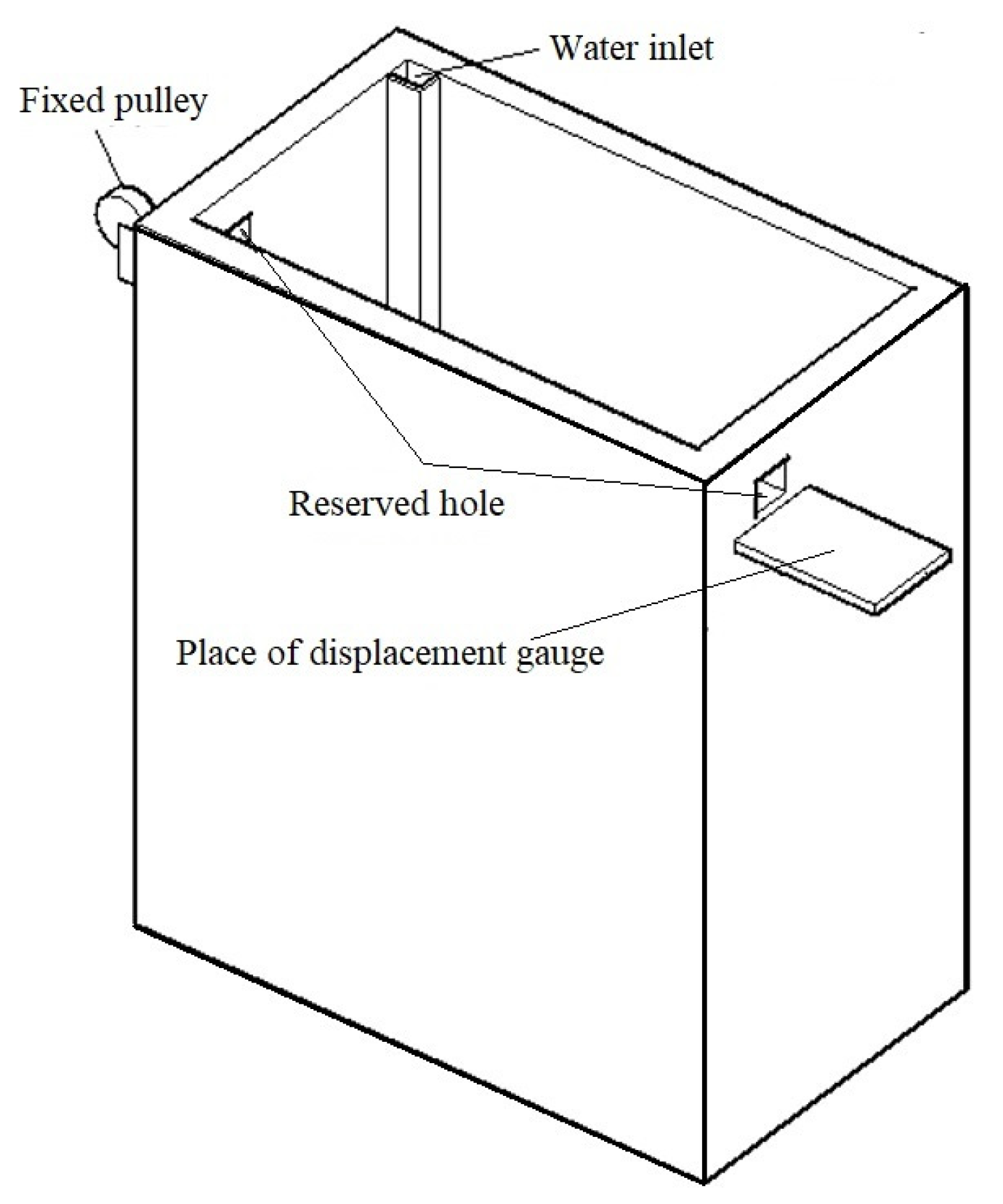
2.1. Model Box

This research employed a scaled model test of a single pile under lateral loading. The size of the model box used was 230 mm in length, 180 mm in width, and 320 mm in height. Fixed pulleys were installed on the outer wall of the model box to ensure that the lateral loading application direction is horizontal. A working platform with a laser displacement meter was installed at the elevation of the pile top and on the other side of a fixed pulley device. At the corner of the model box, a water level observation pipe was set up with a 5 mm thick plexiglass plate. The pipe had a permeable hole at the bottom of the model box. The pipe simultaneously served as a channel for groundwater packing. The model box design is shown in Figure 1.

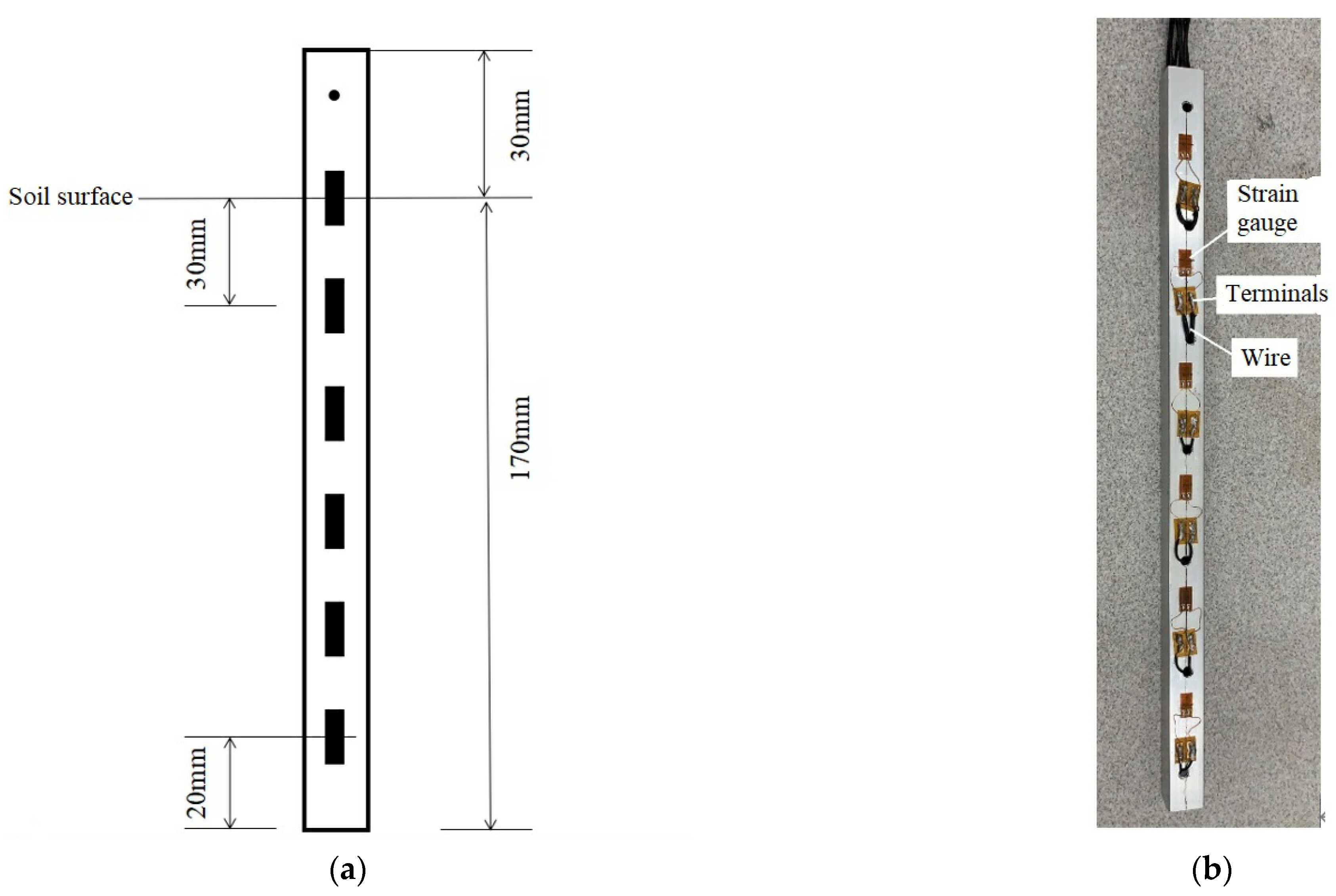
2.2. Test Model Pile
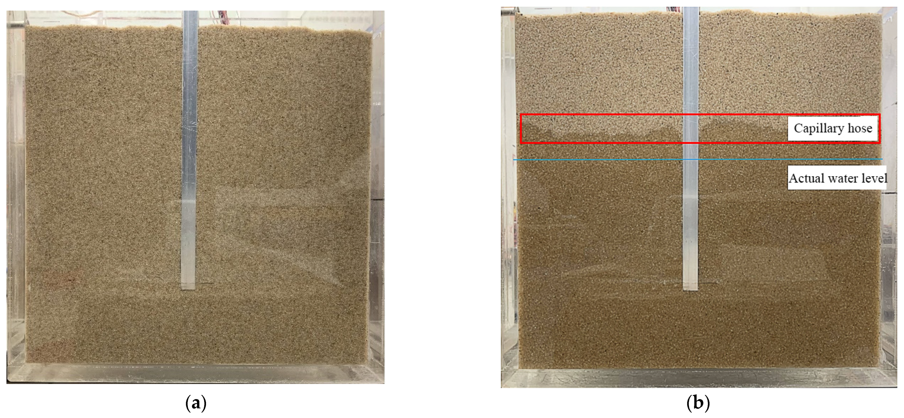
The prototype of this test was a C80 large-diameter anti-slide concrete square pile with a width of 3 m, a length of 6 m, and a height of 60 m. For the scaled model test, geometric similarity, motion similarity, dynamic similarity and constitutive similarity are necessary conditions in producing consistent experimental results, and the similarity ratio used for similar experimental results is shown in Table 1 [61]. The test selected a size similarity ratio of 1:300 for the model test, so the section size of the half-mold scaled test model pile was 10 mm in length, 10 mm in width, and 200 mm in height. According to the material and size parameters of the prototype, the bending stiffness of the prototype pile was calculated to be 256.5 GN·m2, and the bending stiffness of the converted model pile was 31.6 N·m2. According to this calculated value, a square hollow aluminum tube with an elastic modulus of 60 GPa was selected as the material of the model pile. Its actual bending stiffness was calculated to be 29.5 N·m2. The specific parameters of the model pile are shown in Table 2. The assembled strain gauge on the side of the model pile is shown in Figure 2.

2.3. Test Soil

In order to better control the consistency of the test soil structure when installing the mold and reduce the interference caused by the uneven assembly of soil particles on the test results, this test selected poorly graded Fujian standard sand. The physical properties of the soil particles are shown in Table 3, the relative density is 2.64, the maximum pore ratio is 0.855, and the minimum pore ratio is 0.604. The mass of sand required to achieve a relative compactness of Dr = 0.3 can be obtained through Equations (1) and (2). The filling steps are as follows: (1) filling in layers, with each layer filled to a thickness of 50 mm, and the speed of filling was slow enough to obtain a loose soil particle structure. (2) When the filling thickness of the soil in the model box reached 150 mm, the model pile should be set to the inner wall of the model box, the verticality of the model pile should be corrected, and then continue to fill. (3) After filling the soil, the tube was placed at the bottom of the water inlet of the model box, and then the peristaltic pump was used to fill the sand with water. In order to ensure that the compactness of the sand was not affected by the dynamic hydraulic force during the water filling process, the peristaltic pump was set to work at a slow speed of 20 revolutions per minute. The sample is shown in Figure 3.
Table 3. Physical parameters of Fujian standard sand.
Specific Gravity
ds
(g/cm3)
Minimum Dry Density
ρdmin
(g/cm3)
Maximum Dry Density
ρdmax
(g/cm3)
Minimum Void Ratio
emin
Maximum Void Ratio
emax
Internal Friction Angle (°)
2.641.3321.6280.6040.85536
Figure 3. The sand packed in the box. (a) Packed sand. (b) Packed sand with groundwater.
Fractalfract 06 00198 g003
D r = e max e e max e min
ρ d = d s ρ w 1 + e
D r —Relative density of soil;
e —The current void ratio of the soil;
ρ d —Pore volume;
d s —Relative density of soil;
ρ w —The density of water.

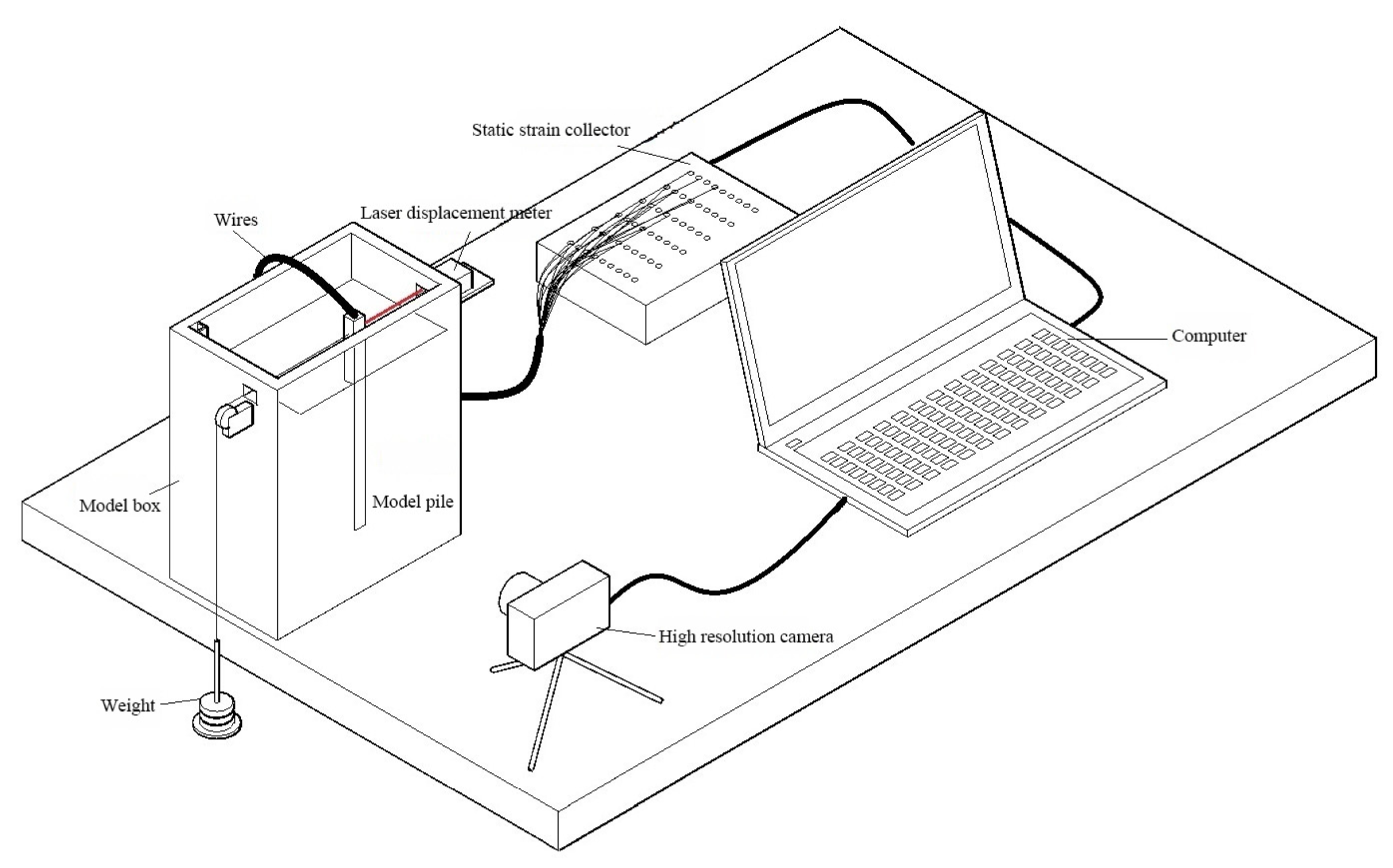
2.4. Acquisition System

Currently, in the field of displacement measurement, PIV is the most commonly used soil deformation measurement technology. Stanier et al. [62] and White et al. [63], from the University of Cambridge, first applied this speed measurement technology to geotechnical engineering tests. Gudehus and Nubel [64] used PIV technology in physical models to study the properties of soil particles and visualize the soil shear zones. Because of its technical advantages, such as relatively simple equipment and convenient operation, this technology has gained considerable popularity and additional development in the field of geotechnical engineering over the years [65]. Yuan et al. found that the PIV technology could be used as an application in measuring the displacement field of soil, especially in the study of the soil settlement around the pile and the foundation [66].
The collection of data in this experiment was divided into the collection of movement images of the piles and soil, the collection of pile top displacement, and the collection of pile body strain. In the first phase of data collection, a high-resolution camera was used to make images of the front of the model box. A Panasonic HG-C1030 laser displacement meter was used to collect the change of the pile top displacement during the test loading process. Finally, a computer was connected to the Donghua Test DH3815N static strain collector to collect information relevant to pile strain. The schematic diagram of the overall model test device is shown in Figure 4. The test system mainly consisted of a model box, a model pile, a static strain collector, a high resolution camera, and a computer.

2.5. Cyclic Loading Test Plan

The control variables for this test were loading and groundwater depth conditions for ten sets of tests. The number of cyclic loading steps for each set of tests is 20. Five different groundwater depth conditions were set: dry sand, saturated sand, a groundwater depth of 40 mm, a groundwater depth of 90 mm, and a groundwater depth of 140 mm. Two loads with different load peaks were set for cyclic loading, 3 N and 4 N respectively. The test was divided into ten groups. The test plan and test group numbers are shown in Table 4. The specific test process was as follows.
The model box was filled with sand in layers. After the filling, the sand was left to stand for 1 h, allowing the soil particles in the model box to stabilize. Then the camera was turned on to record the front of the box, the laser displacement meter was turned on, the strain collector was turned on, and the relevant parameters were set on the computer. In this study, the weights were used to produce the cyclic loading, and one hundred gram weights were loaded and/or unloaded sequentially, with an interval of about 30 s between each step of loading and unloading. The data were recorded after the displacement of the pile top and the strain of the pile body remained unchanged for 10 s.
After the experiment, the model pile was taken out, the water in the soil was pumped out using a peristaltic pump, and the sand was first placed in an oven for 24 h to dry at 105 °C and then placed in a drying oven to air at room temperature. After that procedure, the next experiment could be started.
In order to prevent the occurrence of accidental errors, repeated tests were carried out for each experimental group. If the difference between the two tests (such as the displacement of the pile top and the strain data) was less than 10%, the group with the better photo quality would be selected for analysis. If the error between the two tests was greater than 10%, the test materials and equipment would be necessary to check, and the result would be annulled.

2.6. Theoretical Method

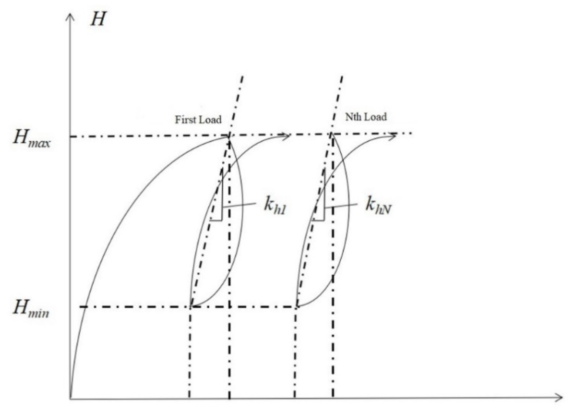
2.6.1. Cyclic Secant Stiffness

For the general research on the cyclic bearing characteristics of laterally loaded piles, the cyclic secant stiffness is a commonly used evaluation parameter in various pile–soil interaction studies. Zhang et al. believed that the cyclic secant stiffness calculated by the cyclic loading amplitude and the full amount of pile deformation was not suitable for evaluating the cyclic bearing characteristics of laterally loaded piles in loose sand foundations [67]. That is because, in the sand, when the pile is subjected to lateral loading, the compression deformation is usually the main factor, and its bearing characteristics increase to a certain extent with the increasing number of cycles. The research of Zhang referred to the previous calculation experience on the cyclic stiffness of the laterally loaded pile and used the cyclic loading amplitude and the lateral deformation increment of the pile to construct the laterally loaded pile cyclic stiffness parameter. The calculation method is shown in Figure 5.
The lateral cyclic stiffness of the laterally loaded pile under the Nth cyclic loading is:
k h N = H max H min y N max y N min
H max —Peak cyclic loading;
H min —Minimum value of cyclic loading;
y N max —The maximum displacement at the Nth cycle;
y N min —Cumulative displacement at the Nth cycle.

2.6.2. Fractal Dimension

In fractal theory, fractal dimension is a quantitative index whose value increases with the increase of complex shapes and forms of graphics [53]. The effective value of fractal dimension depends on the proper calculation method, in which the box-counting method is usually used [68].
In the box counting method, a divided mesh with a grid length of h is used to cover the image whose fractal dimension needs to be calculated. Then, the number of grids overlapped with the graphic characters in the image is counted as “N(h)”. When h is constantly changing, the relationship between h and N(h) can be obtained and expressed by Equation (4).
N ( h ) = k h D
where D = fractal dimension; h = grid length; N(h) = number of grids; and k is a constant. D can be obtained by removing logarithm from both sides of Equation (4), as shown in Equation (5).
ln N ( h ) = D ln h + ln k
It is easy to know that D is the slope of the logarithmic equation represented by Equation (5). The image processing process is shown in Figure 6. First, the image is binarized, and then meshed. In this paper, the fractal dimension of Figure 7 and Figure 8 is calculated.

3. Results and Discussion

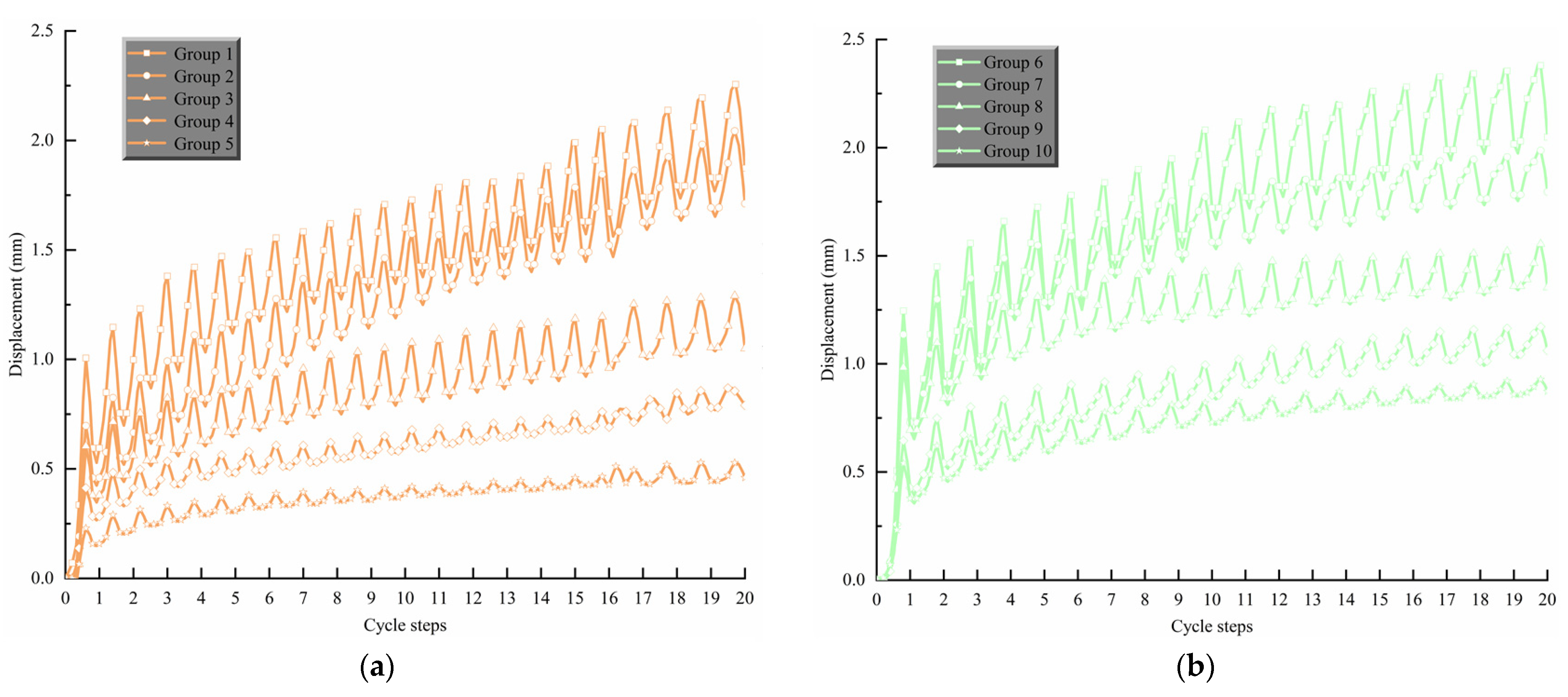
3.1. Analysis of Cumulative Displacement of Pile Top Cyclic Loading

The displacement curve of the pile top under each step of cyclic loading was obtained by measuring the displacement of the pile top of the model pile on the soil surface. The test analysis results are shown in Figure 7. Loading each test to the same number of steps, the cumulative pile top displacement with a cyclic loading peak of 3 N is sorted in descending order of group 1, group 2, group 3, group 4, group 5, and the cumulative pile top displacement with a cyclic loading peak value of 4 N is in descending order of group 6, group 7, group 8, group 9, and group 10.
Figure 7. Curve of pile top displacement—cyclic loading steps. (a) Hmax = 3 N Hmin = 0 N. (b) Hmax = 4 N Hmin = 0 N.
Fractalfract 06 00198 g007
The detailed incremental data of the displacement of each test pile top with the increase of cycle steps are shown in Table 5.
The detailed data of accumulated pile top displacement are obtained after processing the data in Figure 7. Groups 6 to 10 showed the ratio of the cumulative pile top displacement in the first step to the cumulative pile top displacement in the twentieth step exceeded by 35%. That is to say, the plastic deformation caused by the pile body to the soil around the pile is the largest during the first cyclic loading, and, as the number of cyclic steps increases, the cumulative displacement increment of the pile top of each test pile decreases, which is consistent with the conclusion of previous cyclic loading tests in sand with different densities [67]. The short-term effect of cyclic cumulative displacement of a laterally loaded pile is greater than its long-term effect.
Several more representative data were obtained after processing the cumulative displacement increment of the pile top, as shown in Table 5. yNmin in the table is the cumulative pile top displacement at the end of the Nth cycle; E(δ) is the average increment of the cumulative pile top displacement between each cycle step after the first cyclic loading; and S2(δ) is the variance of the cumulative pile top displacement increment data group between each step. COV is the covariance between the cumulative pile top displacement and the number of cycle steps. COV is a measure of how much the cumulative pile top displacement and the number of cycle steps move together. S2(δ) shows the change of pile top displacement better than E(δ). S2(δ) shows that, when the laterally loaded pile is subjected to cyclic loading, the degree of dispersion of the cumulative plastic deformation increment data of the pile top is related to the ability of the soil around the pile to limit the lateral displacement of the pile.
It can be seen from Table 5 that the COV of all experimental groups is greater than zero, which means a strong positive relationship between the cumulative displacement of the pile top and the number of cycle steps. Under the lateral cyclic loading with the same peak value, as the water level drops, both E(δ) and S2(δ) decreased. This shows that the lowering of the groundwater level can increase the soil mass and limit the displacement of the soil around the pile. At the same time, it can be seen that the E(δ) and S2(δ) of dry sand are slightly lower than those of saturated sand. This is because, on the one hand, as the groundwater level is at the soil surface, hydrostatic pressure will reduce the effective stress of the soil particles, thereby, reducing the strength of the soil [24,25]. That is the ability to restrict the movement of the pile is reduced, and finally the displacement of the pile top will increase. On the other hand, as the groundwater level rises, the buoyancy of the groundwater on the pile is also greater, which reduces the effect of soil on the pile and also causes the displacement of the pile top to increase.

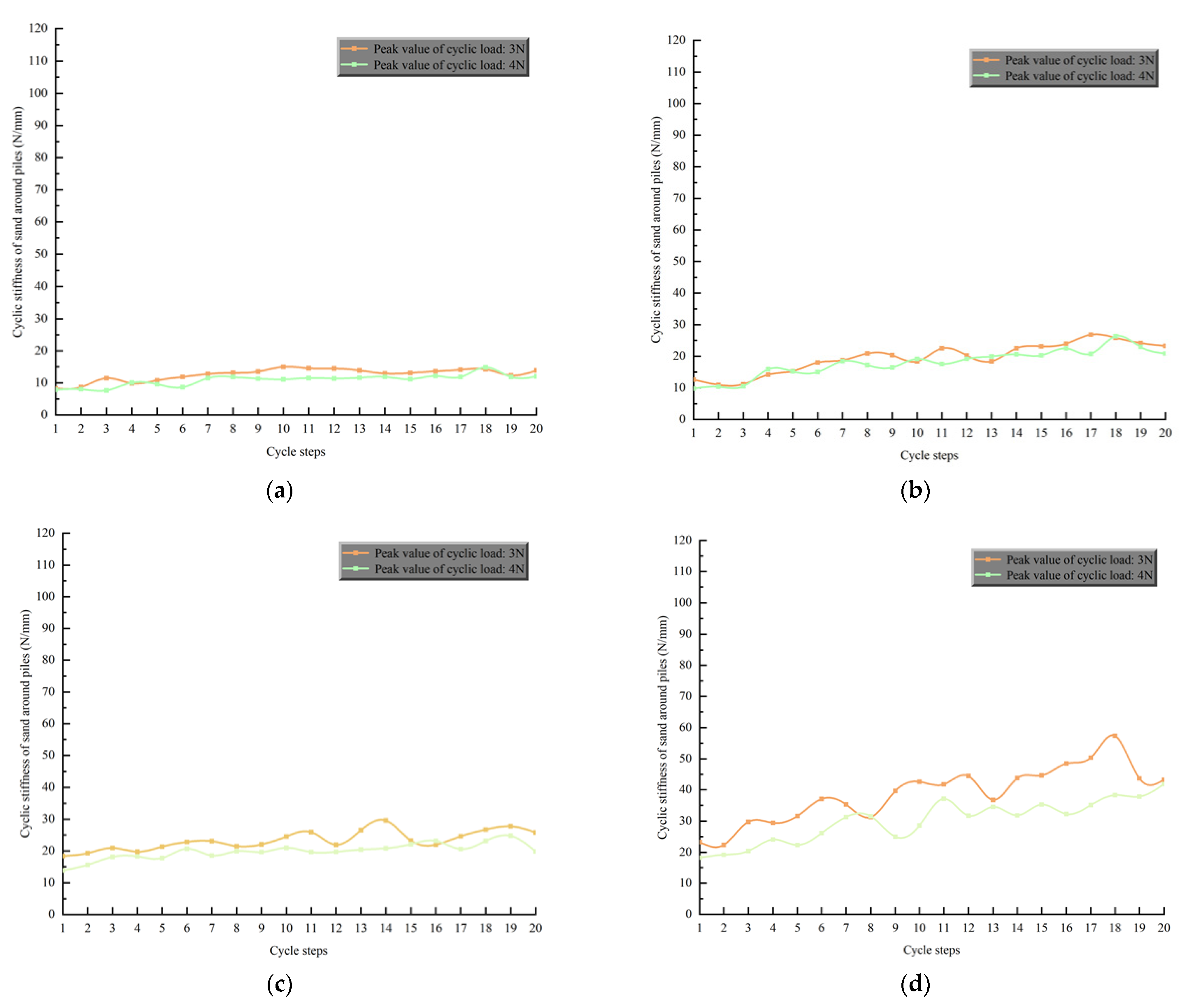
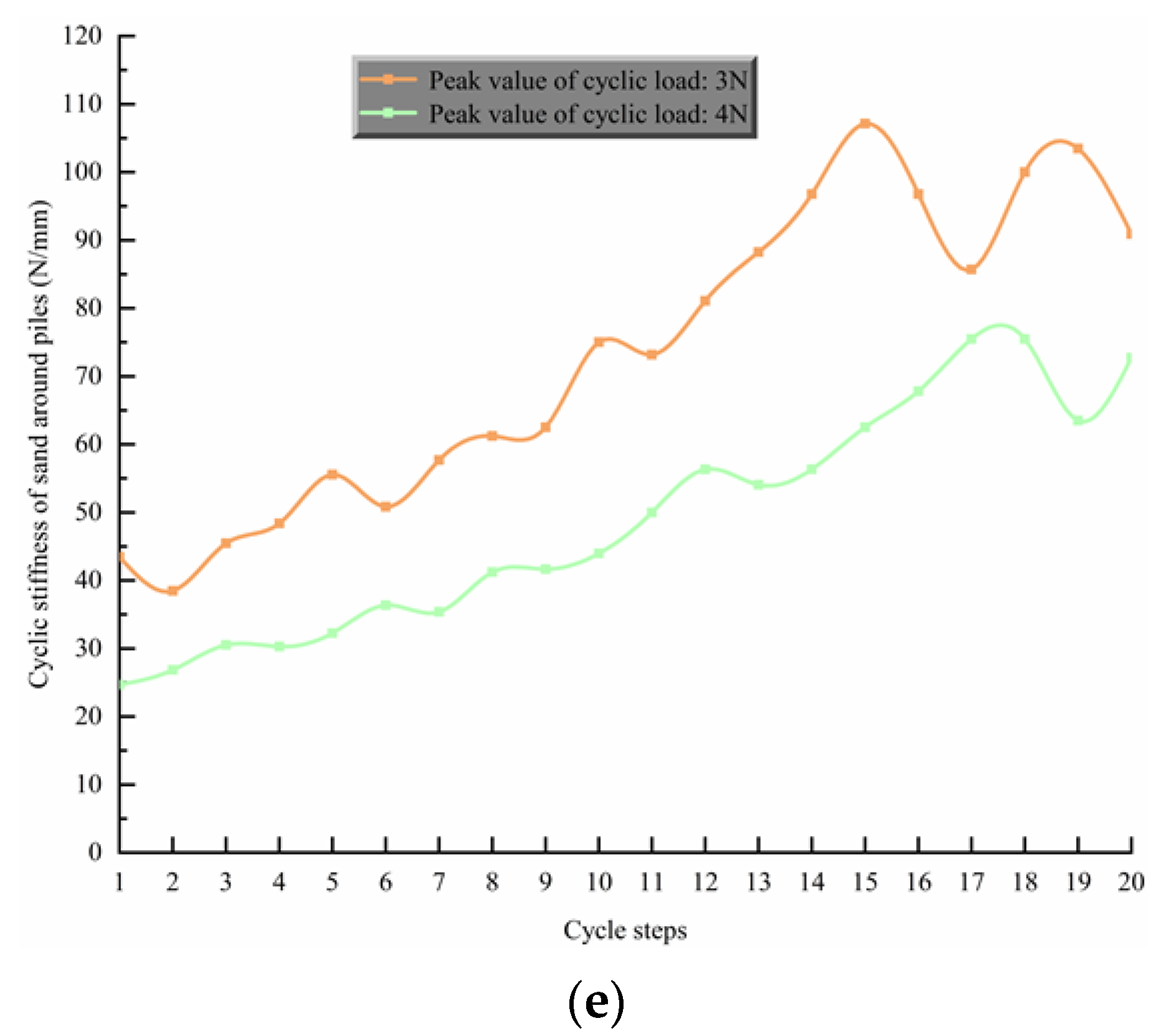
3.2. Analysis of Cyclic Stiffness of Sand around Pile

According to Figure 8, the cyclic stiffness of the soil increases gradually with the number of cycles for different cyclic load magnitudes and different groundwater levels. For example (Figure 8e), with cyclic peak load Hmax of 3 N and Hmin of 0 N, kh1 = 43.82 N/mm and kh20 = 91.93 N/mm, the cyclic stiffness at the 20th cyclic loading was 2.1 times higher than that at the 1st. Obviously, this is different from the general conclusion that cyclic loading leads to the weakening of soil stiffness [42]. This is mainly because the self-weight stress provided by the soil in the model test is low, while the deformation of sand under low confining pressure is usually dominated by compression.
It was noteworthy that both the lateral initial and cyclic stiffness decreased with the increase of the cyclic loading amplitude. For example (Figure 8e), at Hmax = 3 N, kh1 = 43.82 N/mm and kh20 = 91.93 N/mm. At Hmax = 4 N, kh1 = 24.92 N/mm and kh20 = 73.26 N/mm. As the loading amplitude rose, the difference between the maximum and minimum displacements during a single cycle increased. This indicates that the cumulative deformation of the monopile increases with the cyclic loading amplitude. This is similar to the conclusion reached by Malakshah et al. in calcareous sands [47], and it also shows that the response behavior of the pile–soil system under cyclic loading is less affected by the type of soil.
Figure 8. Curve of cyclic stiffness of sand around piles—cycle steps. (a) Group 1 and Group 6, (b) Group 2 and Group 7, (c) Group 3 and Group 8, (d) Group 4 and Group 9, (e) Group 5 and Group 10.
Fractalfract 06 00198 g008aFractalfract 06 00198 g008b
Taking the test groups with a loading amplitude of 3 N as an example, when the loading conditions remain unchanged, kh20 = 13.82 N/mm in the saturated sand test and kh20 = 23.47 N/mm in the dry sand test. Compared with the dry sand test, when the soil was saturated (the groundwater level was at the soil surface), the ability of the sand to limit the displacement of the pile was significantly weakened. The suction stress in saturated soil was the pore water pressure [25]. The grain spacing between soil particles became larger, the effective stress was reduced, and the soil strength decreased. It can be seen that the presence of groundwater can significantly impact the mechanical properties of sand.
When the water level was lower than the soil surface, the constraining capacity of the sand to the laterally loaded piles was obviously enhanced compared to the dry sand test, and the growth rate of the cyclic stiffness of each group was affected by the change in water levels. For example, in the 140 mm groundwater depth tests (Figure 8c), the cyclic stiffness at the 20th cycle increased by 40.3% and 43.2% when compared with the first cycle, the corresponding growth rates in the 90 mm groundwater depth tests (Figure 8d) were 85.9% and 129%, and the corresponding growth rates in the 40 mm groundwater depth tests (Figure 8e) were 109.8% and 194.3%. In Bishop’s effective stress, the capillary pressure is regarded as the matrix suction, and this theory is widely adopted in many disciplines [69]. Lowering the water level causes capillary stress or matrix suction to develop above the water level. Capillary water can be considered as a fluid with an isotropic negative pore water pressure in the unsaturated soil. The shrink film produced by the capillary water bears an air pressure greater than the water pressure [23,25], which affects the effective stress of the soil and the strength of the soil is increased. The capillary layer moved down and the growth rate of cyclic stiffness decreased as the groundwater level dropped. This is because the shallow soil has a greater influence on the pile–soil system compared to the deep sand [70].

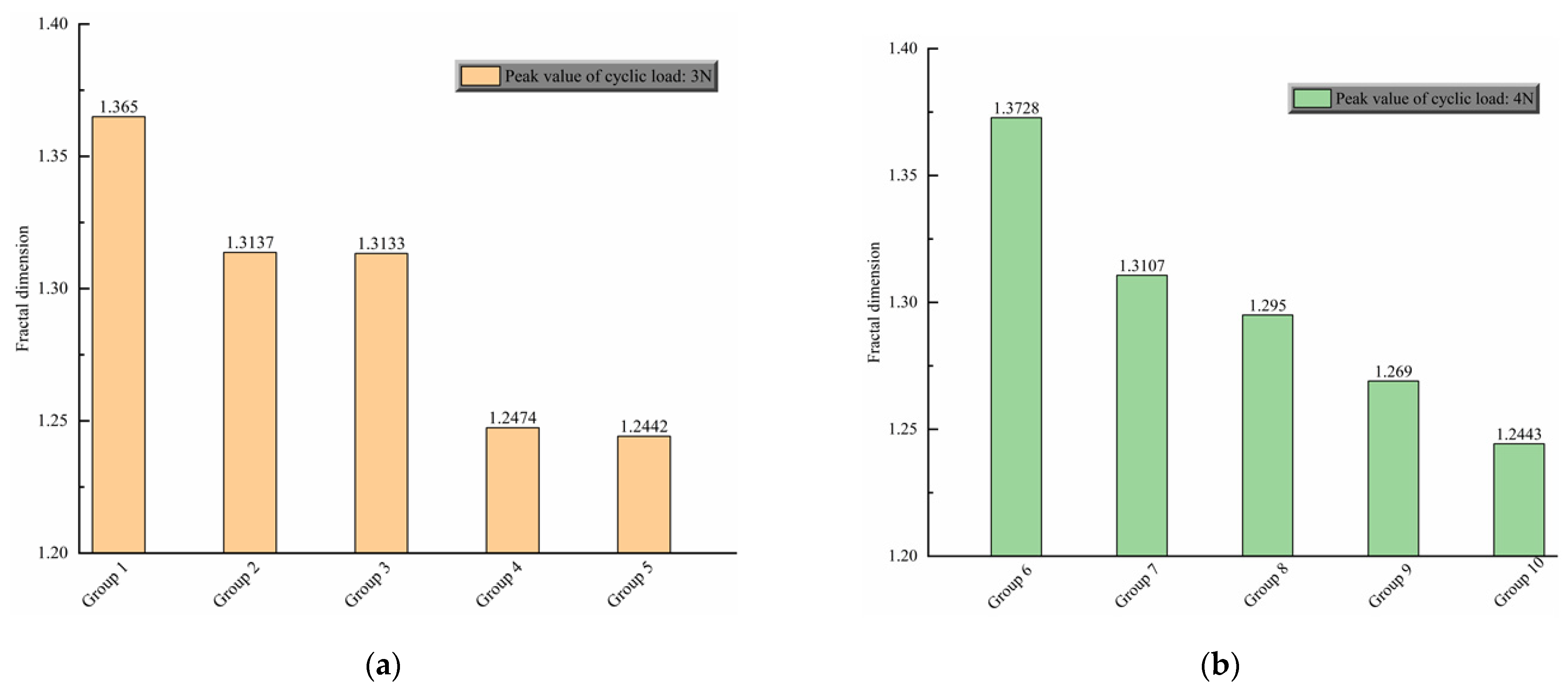
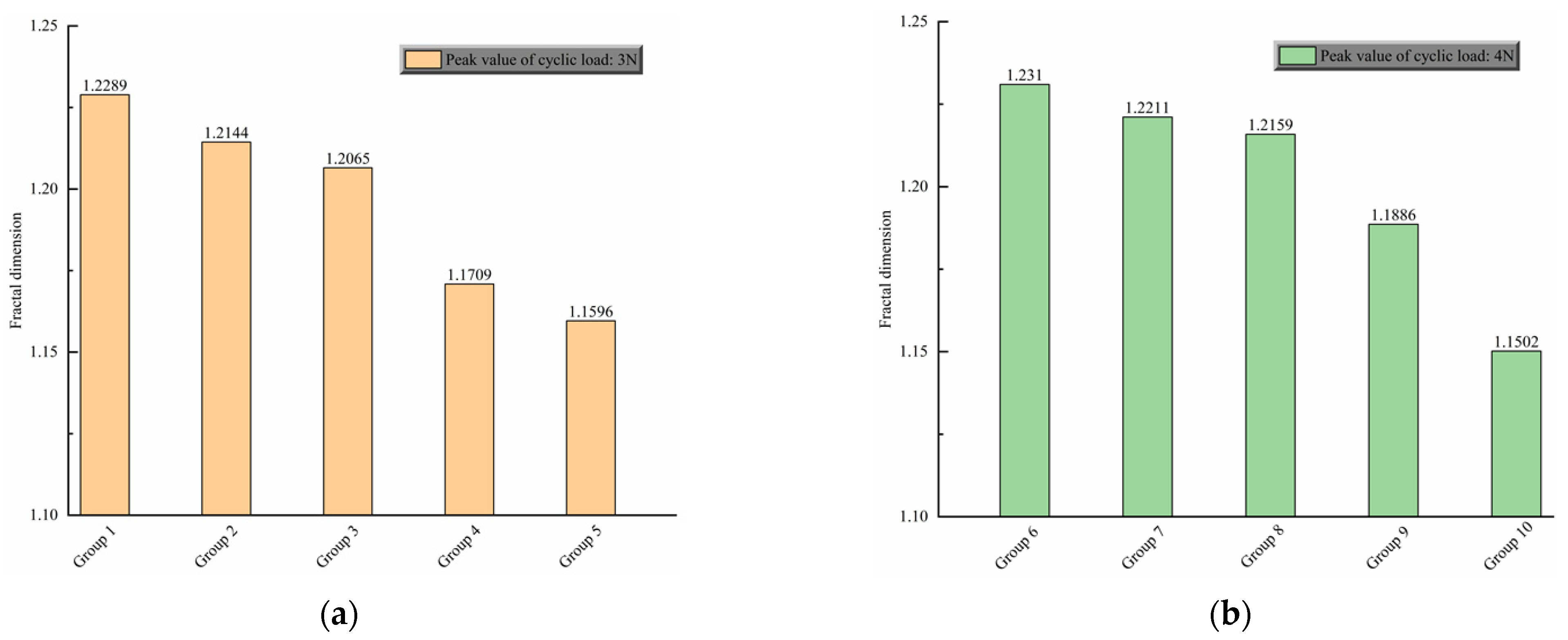
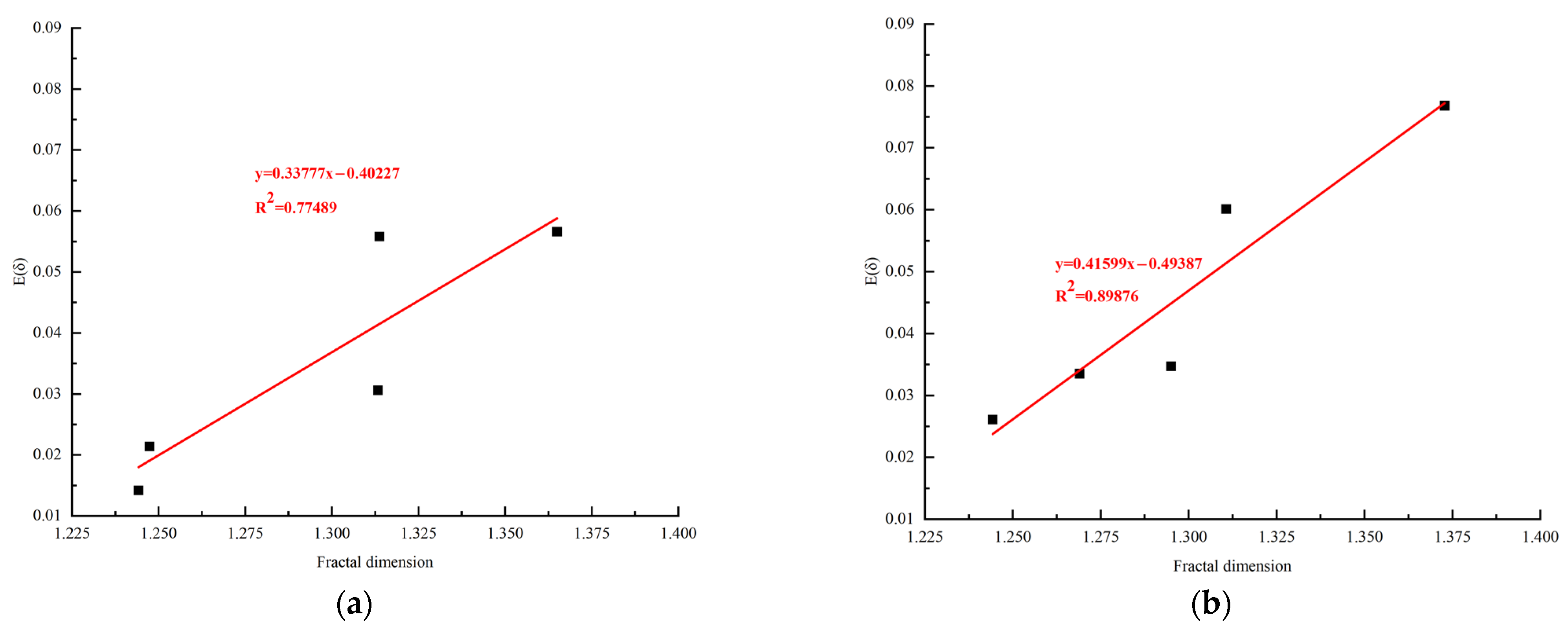
3.3. Analysis of Fractal Dimension

Fractal dimension can describe the fluctuation degree of curve quantitatively. The higher the fractal dimension, the greater the fluctuation of the curve. The curves of the relationship between the pile top displacement and cycle steps are zigzag and has obvious fractal characteristics. The curve of the relationship between the cyclic stiffness of the sand around the pile and cycle steps also has the same fractal characteristics.
Figure 9 shows the fractal dimension of the curve of the relationship between the pile top displacement and the cycle steps. Taking the peak cyclic load 4 N as an example (Figure 8b), the fractal dimension decreases in the order of saturated sand (group 6), dry sand (group 7), and groundwater depth 140 mm (group 8), 90 mm (group 9) and 40 mm (group 10), which are 1.3728, 1.3107, 1.295, 1.269, and 1.2443, respectively. The lower the fractal dimension, the smoother the displacement curve, which means the difference between ymax and ymin of the pile in each cycle is small. In other words, the high resistance ability of the soil to deformation represents a small fractal dimension. The displacement of pile top mainly depends on the behavior of shallow sand. Compared with dry sand, the shallower the groundwater table is, the more obvious the matric suction caused by capillary water rising strengthens the shallow sand, which leads to the smaller the fractal dimension.
However, as far as saturated sand is concerned, the shallow sand is saturated and the matric suction has disappeared. The water film between the sand particles in the shallow sand plays a “lubricating role”, which makes the sliding between the sand particles easier. Therefore, under the action of cyclic load, the displacement range of sand is naturally the largest, and the fractal dimension is also the largest. When the peak cyclic load is 3 N (Figure 9a), the fractal dimensions are 1.365, 1.3137, 1.3133, 1.2474, and 1.2442 respectively, which is similar to the law when the peak cyclic load is 4 N.
Figure 10 shows the fractal dimension of the curves of the stiffness of sand around piles and cycle steps. It can be seen from Figure 10a that the fractal dimensions of group 1 to group 5 are 1.2289, 1.2144, 1.2065, 1.1709, and 1.1596 respectively, which indicates that under the condition of saturated sand, the change amplitude of sand stiffness is the largest. However, when the buried depth of groundwater level is 40 mm, the change amplitude is the smallest. In Figure 10b, the fractal dimensions of group 6 to group 10 are 1.231, 1.2211, 1.2159, 1.1886, and 1.1502, respectively. By comparing the fractal dimensions of Figure 9a,b, it can be seen that the change amplitude of sand stiffness under the peak cyclic load of 4 N is larger than that under the peak cyclic load of 3 N when the groundwater depth is the same.
In order to explore the sensitivity of pile top displacement to cyclic steps under different groundwater depths, the relationship between displacement fluctuation index and fractal dimension is discussed. Figure 11 shows the linear fitting results of the variance and fractal dimension of the accumulated pile top displacement increment data group between each cycle step. The slope of linear fitting line is 0.04265 when the peak value of cyclic load is 4 N, which is higher than 0.01043 when the peak value of cyclic load is 3 N, indicating that the increase of peak value of cyclic load will increase the sensitivity of pile top displacement to cyclic steps. Obviously, there is a strong positive correlation between them, which means that the larger the fractal dimension is, the stronger the sensitivity of pile top displacement to cyclic steps is. Moreover, the correlation between fractal dimension and the mechanical response of the pile–soil system is also further verified. The value of the fractal dimension can reflect the change of the pile–soil system under various environmental circumstances.
In addition, the average increment and fractal dimension of cumulative pile top displacement between each cyclic step after the first cyclic load are fitted and analyzed, and the results are shown in Figure 12. They also showed a good positive correlation.

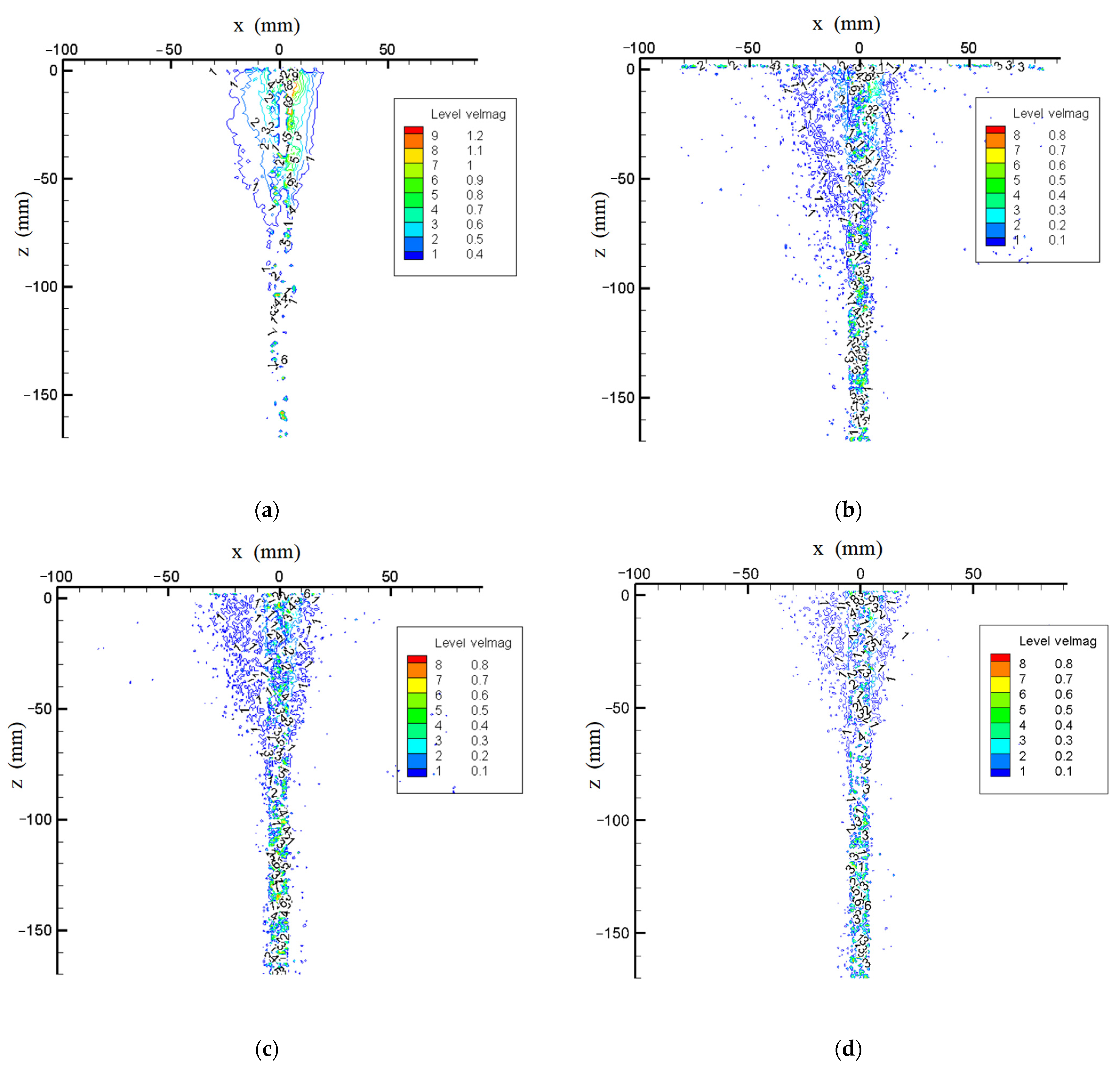
3.4. Comparative Analysis of the Change Law of Soil Displacement Field

Research by Yuan et al. explained how to obtain the spot pattern needed to calculate the soil displacement field [71]. Using that information, this research process applied PIVview2C software to process the images taken during the cyclic loading peak Hmax = 4 N test process to obtain the soil particle displacement field data between the key frames during each step of the cyclic loading process, and then imported it into the TECPLOT software for displacement field equivalence line drawing [72]. This section analyzes the mechanism of pile–soil interaction in soil under cyclic loading from the macroscopic view of particle movement.
There were five sets of experiments in this experiment, and the practice associated with each set of images was the same. Therefore, a set of representative PIV images at a groundwater depth of 90 mm was selected. The PIV images after the first, second, tenth, and twentieth cyclic loadings are as shown in Figure 13. As shown in Figure 13a, the main deformation of the soil around the pile occurred in the first cycle. Initially, the soil displacement was induced within 20 mm of the pile circumference, and the soil displacement was most obvious at a distance of 10 mm around the pile circumference. The image after the second cyclic loading is shown in Figure 8b. Most of the soil displacement was concentrated within 40 mm around the pile circumference, and the soil displacement at a distance of 10 mm around the pile circumference was still the most obvious. The image after the tenth cyclic loading is shown in Figure 13c. Compared with the second loading, the soil displacement range was significantly reduced, and the soil displacement was concentrated within 30 mm of the pile circumference. The image after the twentieth loading is shown in Figure 13d. The soil displacement particles are obviously sparse, and the soil displacement range is reduced to within 20 mm.
The reason for this phenomenon is that the displacement of sand grains in the vertical direction is predisposed to occur, resulting in the volume change of the soil remaining largely compressible and maintaining a lot of room for strength. When the cyclic loading reaches the peak state, the shear zone will form in the core area around the pile. As the deformation further increases, the shear zone begins to develop around the pile, and the sand on both sides of the pile gradually slips and the strength decreases slowly. When the shear band is misaligned to a certain extent, under the action of false cohesion, the soil around the pile reaches the static equilibrium state again, and no new slip occurs. At this point, the soil around the pile reaches a stable residual state, and the displacement of the pile only disturbs the soil around the pile within a certain range.

4. Conclusions

An original pile–soil test platform combined with PIV was designed for conducting horizontal loading tests on a monopile with the groundwater level and loading amplitude as variables under the unidirectional lateral cyclic loading. The pile–soil system was significantly affected by the cyclic loading, and the lateral stiffness of the soil increased as the loading proceeded. It was evident from the PIV images that the short-term effects of cyclic loading on the pile are much greater than the long-term effects. The disturbance range of soil around the pile rose with the increase in the number of cycles in the first ten cycles of loading. The soil structure was reconstructed, and the disturbance range of the soil around the pile gradually shrank and stabilized in the final ten cycles of loading. With a higher loading amplitude, the initial and cyclic stiffness of the soil would be less. The growth rate of cyclic stiffness was reduced as the groundwater level dropped. The stiffness of dry sand was greater than the stiffness of saturated soil, but less than the stiffness of the soil when the water table was below the soil surface, a difference due to matrix suction. Fractal theory was introduced to analyze the curves of the pile top displacement and the curve of the cyclic stiffness of the sand. The larger the fluctuation amplitude of the curve, the larger the fractal dimension. Both the variance and the average increment of the cumulative pile top displacement between each cycle step were positively correlated with fractal dimension. Therefore, a new physical meaning was given to fractal dimension, which meant fractal dimension could reflect the load response of the pile–soil system under cyclic loading.
The study outcome is expected to deepen understanding of the physical process and fundamental principles of the response of laterally loaded piles and sand bodies under different groundwater depths. However, this study was limited to a single soil layer. Further research is needed to explore the interaction mechanism of the pile–soil system during changes in groundwater levels under complex stratified soil in order to provide a better reference for the project monitoring.

Author Contributions

Data curation, Z.L. and W.C.; formal analysis, Z.L. and J.L.; investigation, W.C.; methodology, B.Y.; project administration, B.Y.; software, Z.L. and J.Z.; supervision, X.C. and J.S.; writing—original draft, B.Y. and Z.L.; writing—review and editing, B.Y. and J.L. All authors have read and agreed to the published version of the manuscript.

Funding

The authors would gratefully like to acknowledge the support provided by the National Natural Science Foundation of China (No. 51978177).

Institutional Review Board Statement

Not applicable.

Informed Consent Statement

Not applicable.

Data Availability Statement

The data presented in this study are available on request from the corresponding author. The data are not publicly available due to intellectual property.

Acknowledgments

The authors would like to thank all the referees for their constructive comments and suggestions. The editorial help from Galen Leonhardy of Black Hawk College is also greatly appreciated.

Conflicts of Interest

No conflict of interest exits in the submission of this manuscript, and manuscript is approved by all authors for publication.

References

  1. Sunday, K.; Brennan, F. A review of offshore wind monopiles structural design achievements and challenges. Ocean Eng. 2021, 235, 109409. [Google Scholar] [CrossRef]
  2. van der Male, P.; Vergassola, M.; van Dalen, K.N. Decoupled Modelling Approaches for Environmental Interactions with Monopile-Based Offshore Wind Support Structures. Energies 2020, 13, 5195. [Google Scholar] [CrossRef]
  3. O’Kelly-Lynch, P.; Long, C.; McAuliffe, F.D.; Murphy, J.; Pakrashi, V. Structural design implications of combining a point absorber with a wind turbine monopile for the east and west coast of Ireland. Renew. Sustain. Energy Rev. 2020, 119, 109583. [Google Scholar] [CrossRef]
  4. Rathod, D.; Krishnanunni, K.T.; Nigitha, D. A Review on Conventional and Innovative Pile System for Offshore Wind Turbines. Geotech. Geol. Eng. 2020, 38, 3385–3402. [Google Scholar] [CrossRef]
  5. Vicedo, J.S.; Barba, J.G.; Frades, J.L.; Valdecantos, V.N. Scale Tests to Estimate Penetration Force and Stress State of the Silica Sand in Windfarm Foundations. Energies 2021, 14, 5904. [Google Scholar] [CrossRef]
  6. Schweizer, J.; Antonini, A.; Govoni, L.; Gottardi, G.; Archetti, R.; Supino, E.; Berretta, C.; Casadei, C.; Ozzi, C. Investigating the potential and feasibility of an offshore wind farm in the Northern Adriatic Sea. Appl. Energy 2016, 177, 449–463. [Google Scholar] [CrossRef]
  7. Wang, X.F.; Zeng, X.W.; Yang, X.; Li, J.L. Feasibility study of offshore wind turbines with hybrid monopile foundation based on centrifuge modeling. Appl. Energy 2018, 209, 127–139. [Google Scholar] [CrossRef]
  8. Zou, X.J.; Cao, X.; Zhou, C.L.; Zhou, M.; Zhang, X.H. Experimental study on the bearing capacity of large-diameter monopile in sand under water flow condition. Ocean Eng. 2021, 224, 108708. [Google Scholar] [CrossRef]
  9. McAdam, R.A.; Byrne, B.W.; Houlsby, G.T.; Beuckelaers, W.J.A.P.; Burd, H.J.; Gavin, K.G.; Igoe, D.J.P.; Jardine, R.J.; Martin, C.M.; Wood, A.M.; et al. Monotonic laterally loaded pile testing in a dense marine sand at Dunkirk. Geotechnique 2020, 70, 986–998. [Google Scholar] [CrossRef]
  10. Wang, J.Y.; Sun, G.D.; Chen, G.S.; Yang, X. Finite element analyses of improved lateral performance of monopile when combined with bucket foundation for offshore wind turbines. Appl. Ocean Res. 2021, 111, 102647. [Google Scholar] [CrossRef]
  11. Li, J.L.; Zhang, Y.; Wang, X.F.; Sun, Z.Z. Assessment of offshore wind turbine with an innovative monopile foundation under lateral loading. Ocean Eng. 2021, 237, 109583. [Google Scholar] [CrossRef]
  12. Li, F.; Zhu, Z.Y.; Tian, P.S.; Hu, D.; Li, Y.F. The behavior of monopile embedded in sand under scour and cyclic loading conditions. Mar. Georesour. Geotechnol. 2022, 40, 52–63. [Google Scholar] [CrossRef]
  13. Que, X.C.; Zhu, Z.D.; Niu, Z.H.; Lu, W.N. Estimating the strength and deformation of columnar jointed rock mass based on physical model test. Bull. Eng. Geol. Environ. 2021, 80, 1557–1570. [Google Scholar] [CrossRef]
  14. Shao, J.L.; Zhang, Q.; Wu, X.T.; Lei, Y.; Wu, X.A.; Wang, Z.Y. Investigation on the Water Flow Evolution in a Filled Fracture under Seepage-Induced Erosion. Water 2020, 12, 3188. [Google Scholar] [CrossRef]
  15. Bai, B.; Zhou, R.; Cai, G.Q.; Hu, W.; Yang, G.C. Coupled thermo-hydro-mechanical mechanism in view of the soil particle rearrangement of granular thermodynamics. Comput. Geotech. 2021, 137, 104272. [Google Scholar] [CrossRef]
  16. Bai, B.; Nie, Q.K.; Zhang, Y.K.; Wang, X.L.; Hu, W. Cotransport of heavy metals and SiO2 particles at different temperatures by seepage. J. Hydrol. 2021, 597, 125771. [Google Scholar] [CrossRef]
  17. Yang, B.B.; Liu, J.W.; Zhao, X.M.; Zheng, S. Evaporation and cracked soda soil improved by fly ash from recycled materials. Land Degrad. Dev. 2021, 32, 2823–2832. [Google Scholar] [CrossRef]
  18. Yuan, B.X.; Li, Z.H.; Su, Z.L.; Luo, Q.Z.; Chen, M.J.; Zhao, Z.Q. Sensitivity of Multistage Fill Slope Based on Finite Element Model. Adv. Civ. Eng. 2021, 2021, 6622936. [Google Scholar] [CrossRef]
  19. Wu, Y.; Cui, J.; Huang, J.S.; Zhang, W.; Yoshimoto, N.; Wen, L.W. Correlation of Critical State Strength Properties with Particle Shape and Surface Fractal Dimension of Clinker Ash. Int. J. Geomech. 2021, 21. [Google Scholar] [CrossRef]
  20. Shen, J.H.; Hu, M.J.; Wang, X.; Zhang, C.Y.; Xu, D.S. SWCC of Calcareous Silty Sand Under Different Fines Contents and dry Densities. Front. Environ. Sci. 2021, 9, 303. [Google Scholar] [CrossRef]
  21. Liu, M.M.; Yang, M.; Wang, H.J. Bearing behavior of wide-shallow bucket foundation for offshore wind turbines in drained silty sand. Ocean Eng. 2014, 82, 169–179. [Google Scholar] [CrossRef]
  22. Liu, Z.Y.; Xue, J.F. The deformation behaviour of an anisotropically consolidated kaolin clay under lateral cyclic loading. Mar. Georesour. Geotechnol. 2021. [Google Scholar] [CrossRef]
  23. Maleksaeedi, E.; Nuth, M. Evaluation of capillary water retention effects on the development of the suction stress characteristic curve. Can. Geotech. J. 2020, 57, 1439–1452. [Google Scholar] [CrossRef]
  24. Yang, B.; Su, Y.; He, N.; Zhang, B.; Zhou, X.S.; Zhang, Y. Experimental study on the stable morphology and self-attraction effect of subaqueous barchan dunes. Adv. Powder Technol. 2020, 31, 1032–1039. [Google Scholar] [CrossRef]
  25. Zhang, C.; Lu, N. Unified Effective Stress Equation for Soil. J. Eng. Mech. 2020, 146, 04019135. [Google Scholar] [CrossRef]
  26. Guo, Y.C.; Ye, Y.Y.; Guan-Lin; Lv, J.F.; Bai, Y.L.; Zeng, J.J. Effective usage of high strength steel tubes: Axial compressive behavior of hybrid FRP-concrete-steel solid columns. Thin Walled Struct. 2020, 154, 106796. [Google Scholar] [CrossRef]
  27. Lozano-Minguez, E.; Kolios, A.J.; Brennan, F.P. Multi-criteria assessment of offshore wind turbine support structures. Renew. Energy 2011, 36, 2831–2837. [Google Scholar] [CrossRef] [Green Version]
  28. Liu, F.; Chen, G.X.; Li, L.J.; Guo, Y.C. Study of impact performance of rubber reinforced concrete. Constr. Build. Mater. 2012, 36, 604–616. [Google Scholar] [CrossRef]
  29. Liu, F.; Zheng, W.H.; Li, L.J.; Feng, W.X.; Ning, G.F. Mechanical and fatigue performance of rubber concrete. Constr. Build. Mater. 2013, 47, 711–719. [Google Scholar] [CrossRef]
  30. Damgaard, M.; Bayat, M.; Andersen, L.V.; Ibsen, L.B. Assessment of the dynamic behaviour of saturated soil subjected to cyclic loading from offshore monopile wind turbine foundations. Comput. Geotech. 2014, 61, 116–126. [Google Scholar] [CrossRef]
  31. Devolder, B.; Rauwoens, P.; Troch, P. Application of a buoyancy-modified k-omega SST turbulence model to simulate wave run-up around a monopile subjected to regular waves using OpenFOAM (R). Coast. Eng. 2017, 125, 81–94. [Google Scholar] [CrossRef] [Green Version]
  32. Guo, Y.C.; Xie, J.H.; Zhao, J.B.; Zuo, K.X. Utilization of unprocessed steel slag as fine aggregate in normal- and high-strength concrete. Constr. Build. Mater. 2019, 204, 41–49. [Google Scholar] [CrossRef]
  33. Zhang, X.Y.; Tang, L.; Ling, X.Z.; Chan, A.H.C.; Lu, J.C. Using peak ground velocity to characterize the response of soil-pile system in liquefying ground. Eng. Geol. 2018, 240, 62–73. [Google Scholar] [CrossRef]
  34. Cao, X.L.; Dai, G.L.; Gong, W.M.; Zhou, F.X.; Xu, J. Resistance of saturated soil to a laterally vibrating pile. Soil Dyn. Earthq. Eng. 2021, 141, 106496. [Google Scholar] [CrossRef]
  35. Xie, J. Impedance of Inner Saturated Soil to Horizontally Vibrating Large-Diameter Pipe Piles. Shock Vib. 2021, 2021, 1845109. [Google Scholar] [CrossRef]
  36. Ding, X.M.; Qu, L.M.; Yang, J.C.; Wang, C.L. Experimental study on the pile group-soil vibration induced by railway traffic under the inclined bedrock condition. Acta Geotech. 2020, 15, 3613–3620. [Google Scholar] [CrossRef]
  37. Ren, L.W.; Yang, Q.W.; Kong, G.Q.; Dun, Z.L.; Wang, X.Y. Model Tests on Y-Shaped Piles under Compressive and Lateral Loading in Saturated Sand. Geofluids 2021, 2021, 6978602. [Google Scholar] [CrossRef]
  38. Fattah, M.Y.; Zabar, B.S.; Mustafa, F.S. Effect of saturation on response of a single pile embedded in saturated sandy soil to vertical vibration. Eur. J. Environ. Civ. Eng. 2020, 24, 381–400. [Google Scholar] [CrossRef]
  39. Li, J.H.; Zhang, B.; Shen, C.; Fu, X.L.; Li, W.C. Experimental Study on Local Scour Depth around Monopile Foundation in Combined Waves and Current. Sustainability 2021, 13, 13614. [Google Scholar] [CrossRef]
  40. Li, Q.; Askarinejad, A.; Gavin, K. Impact of scour on lateral resistance of wind turbine monopiles: An experimental study. Can. Geotech. J. 2021, 58, 1770–1782. [Google Scholar] [CrossRef]
  41. Cui, C.Y.; Meng, K.; Xu, C.S.; Liang, Z.M.; Li, H.J.; Pei, H.F. Analytical solution for longitudinal vibration of a floating pile in saturated porous media based on a fictitious saturated soil pile model. Comput. Geotech. 2021, 131, 103942. [Google Scholar] [CrossRef]
  42. Achmus, M.; Kuo, Y.S.; Abdel-Rahman, K. Behavior of monopile foundations under cyclic lateral load. Comput. Geotech. 2009, 36, 725–735. [Google Scholar] [CrossRef]
  43. Lombardi, D.; Bhattacharya, S.; Wood, D.M. Dynamic soil-structure interaction of monopile supported wind turbines in cohesive soil. Soil Dyn. Earthq. Eng. 2013, 49, 165–180. [Google Scholar] [CrossRef]
  44. Arshad, M.; O’Kelly, B.C. Analysis and Design of Monopile Foundations for Offshore Wind-Turbine Structures. Mar. Georesour. Geotechnol. 2016, 34, 503–525. [Google Scholar] [CrossRef]
  45. Feng, W.H.; Liu, F.; Yang, F.; Li, L.J.; Jing, L. Experimental study on dynamic split tensile properties of rubber concrete. Constr. Build. Mater. 2018, 165, 675–687. [Google Scholar] [CrossRef]
  46. Luo, R.P.; Yang, M.; Li, W.C. Numerical study of diameter effect on accumulated deformation of laterally loaded monopiles in sand. Eur. J. Environ. Civ. Eng. 2020, 24, 2440–2452. [Google Scholar] [CrossRef]
  47. Malakshah, R.R.; Moradi, M.; Ghalandarzadeh, A. Centrifuge Modelling of Monopiles in Calcareous Sand Subjected to Cyclic Lateral Loading. Int. J. Civ. Eng. 2022, 20, 195–206. [Google Scholar] [CrossRef]
  48. Namazi, H. Complexity-based analysis of the correlation between stride interval variability and muscle reaction at different walking speeds. Biomed. Signal. Process. 2021, 69, 102956. [Google Scholar] [CrossRef]
  49. Phinyomark, A.; Larracy, R.; Scheme, E. Fractal Analysis of Human Gait Variability via Stride Interval Time Series. Front. Physiol. 2020, 11, 333. [Google Scholar] [CrossRef]
  50. Tabares-Ospina, H.A.; Angulo, F.; Osorio, M. New Method to Calculate the Energy and Fractal Dimension of the Daily Electrical Load. Fractals 2020, 28, 2050135. [Google Scholar] [CrossRef]
  51. Yan, B.W.; Chan, P.W.; Li, Q.S.; He, Y.C.; Shu, Z.R. Characterising the fractal dimension of wind speed time series under different terrain conditions. J. Wind Eng. Ind. Aerodyn. 2020, 201, 104165. [Google Scholar] [CrossRef]
  52. Shu, Z.R.; Chan, P.W.; Li, Q.S.; He, Y.C.; Yan, B.W. Quantitative assessment of offshore wind speed variability using fractal analysis. Wind Struct. 2020, 31, 363–371. [Google Scholar] [CrossRef]
  53. Yang, B.B.; Liu, Y. Application of Fractals to Evaluate Fractures of Rock Due to Mining. Fractal Fract. 2022, 6, 96. [Google Scholar] [CrossRef]
  54. Yang, B.B.; Du, S.T.; Zhao, X.M.; Tang, D.Q.; Yang, C.D. Decision Making of Curriculum Attainment Degree for Engineering Geology Based on Fuzzy Set Theory. Adv. Civ. Eng. 2021, 2021, 1743778. [Google Scholar] [CrossRef]
  55. Wang, L.; Luo, R.Y.; Zhang, W.; Jin, M.M.; Tang, S.W. Effects of Fineness and Content of Phosphorus Slag on Cement Hydration, Permeability, Pore Structure and Fractal Dimension of Concrete. Fractals 2021, 29, 2140004. [Google Scholar] [CrossRef]
  56. Xiao, J.; Qu, W.J.; Jiang, H.B.; Li, L.; Huang, J.; Chen, L. Fractal Characterization and Mechanical Behavior of Pile-Soil Interface Subjected to Sulfuric Acid. Fractals 2021, 29, 2140010. [Google Scholar] [CrossRef]
  57. Li, Y.; Zhang, H.; Huang, M.H.; Yin, H.B.; Jiang, K.; Xiao, K.T.; Tang, S.W. Influence of Different Alkali Sulfates on the Shrinkage, Hydration, Pore Structure, Fractal Dimension and Microstructure of Low-Heat Portland Cement, Medium-Heat Portland Cement and Ordinary Portland Cement. Fractal Fract. 2021, 5, 79. [Google Scholar] [CrossRef]
  58. Wang, L.; Lu, X.; Liu, L.S.; Xiao, J.; Zhang, G.; Guo, F.X.; Li, L. Influence of MgO on the Hydration and Shrinkage Behavior of Low Heat Portland Cement-Based Materials via Pore Structural and Fractal Analysis. Fractal Fract. 2022, 6, 40. [Google Scholar] [CrossRef]
  59. Wang, L.; Guo, F.X.; Yang, H.M.; Wang, Y.; Tang, S.W. Comparison of Fly Ash, Pva Fiber, Mgo and Shrinkage-Reducing Admixture on the Frost Resistance of Face Slab Concrete Via Pore Structural and Fractal Analysis. Fractals 2021, 29, 2140002. [Google Scholar] [CrossRef]
  60. Duan, H.Q.; Zhang, S. Fractal Characteristics of Coal Specimens’ Surface Cracks in Triaxial Conventional Compression and Cyclic Loading Tests. Geotech. Geol. Eng. 2020, 38, 19–29. [Google Scholar] [CrossRef]
  61. Kim, N.S.; Lee, J.H.; Chang, S.P. Equivalent multi-phase similitude law for pseudodynamic test on small scale reinforced concrete models. Eng. Struct. 2009, 31, 834–846. [Google Scholar] [CrossRef]
  62. Stanier, S.A.; Blaber, J.; Take, W.A.; White, D.J. Improved image-based deformation measurement for geotechnical applications. Can. Geotech. J. 2016, 53, 727–739. [Google Scholar] [CrossRef]
  63. White, D.J.; Take, W.A.; Bolton, M.D. Soil deformation measurement using particle image velocimetry (PIV) and photogrammetry. Geotechnique 2003, 53, 619–631. [Google Scholar] [CrossRef]
  64. Gudehus, G.; Nubel, K. Evolution of shear bands in sand. Geotechnique 2004, 54, 187–201. [Google Scholar] [CrossRef]
  65. Georgescu, M.R.; Meslem, A.; Nastase, I.; Sandu, M. Numerical and experimental study of the International Space Station crew quarters ventilation. J. Build. Eng. 2021, 41, 102714. [Google Scholar] [CrossRef]
  66. Yuan, B.X.; Sun, M.; Xiong, L.; Luo, Q.Z.; Pradhan, S.P.; Li, H.Z. Investigation of 3D deformation of transparent soil around a laterally loaded pile based on a hydraulic gradient model test. J. Build. Eng. 2020, 28, 101024. [Google Scholar] [CrossRef]
  67. Zhang, X.; Huang, M.S.; Hu, Z.P. Model tests on cumulative deformation characteristics of a single pile subjected to lateral cyclic loading in sand. Rock Soil Mech. 2019, 40, 933–941. [Google Scholar] [CrossRef]
  68. Prabakar, J.; Sridhar, R.S. Effect of random inclusion of sisal fibre on strength behaviour of soil. Constr. Build. Mater. 2002, 16, 123–131. [Google Scholar] [CrossRef]
  69. Lu, N.; Zhang, C. Soil Sorptive Potential: Concept, Theory, and Verification. J. Geotech. Geoenviron. 2019, 145, 04019006. [Google Scholar] [CrossRef]
  70. Wang, H.; Wang, L.Z.; Hong, Y.; Masin, D.; Li, W.; He, B.; Pan, H.L. Centrifuge testing on monotonic and cyclic lateral behavior of large-diameter slender piles in sand. Ocean Eng. 2021, 226, 108299. [Google Scholar] [CrossRef]
  71. Yuan, B.X.; Sun, M.; Wang, Y.X.; Zhai, L.H.; Luo, Q.Z.; Zhang, X.Q. Full 3D Displacement Measuring System for 3D Displacement Field of Soil around a Laterally Loaded Pile in Transparent Soil. Int. J. Geomech. 2019, 19, 04019028. [Google Scholar] [CrossRef]
  72. Yuan, B.X.; Xiong, L.; Zhai, L.H.; Zhou, Y.F.; Chen, G.F.; Gong, X.; Zhang, W. Transparent Synthetic Soil and Its Application in Modeling of Soil-Structure Interaction Using Optical System. Front. Earth Sci. 2019, 7, 276. [Google Scholar] [CrossRef]
Figure 1. Model box.
Fractalfract 06 00198 g001
Figure 2. Model pile. (a) Layout distance of pile body strain gauge. (b) Model pile.
Fractalfract 06 00198 g002
Figure 4. Overall model test device.
Fractalfract 06 00198 g004
Figure 5. Calculation method for lateral cyclic stiffness of pile.
Fractalfract 06 00198 g005
Figure 6. Image processing procedure. (a) flowchart of image processing. (b) Meshing (box-counting method).
Fractalfract 06 00198 g006aFractalfract 06 00198 g006b
Figure 9. Fractal dimension of the curve of the relationship between the pile top displacement and cycle steps. (a) Peak value of cyclic load: 3 N. (b) Peak value of cyclic load: 4 N.
Fractalfract 06 00198 g009
Figure 10. Curve of cyclic stiffness of sand around piles—cycle steps. (a) Peak value of cyclic load: 3 N. (b) Peak value of cyclic load: 4 N.
Fractalfract 06 00198 g010
Figure 11. Relationship between fractal dimension and variance of the cumulative pile top displacement increment data group. (a) Peak value of cyclic load: 3 N. (b) Peak value of cyclic load: 4 N.
Fractalfract 06 00198 g011
Figure 12. Relationship between fractal dimension and average increment of the cumulative pile top displacement between each cycle step after the first cyclic loading. (a) Peak value of cyclic load: 3 N. (b) Peak value of cyclic load: 4 N.
Fractalfract 06 00198 g012
Figure 13. PIV displacement image after cyclic loading of 90 mm groundwater depth test. (a) After the first cyclic loading. (b) After the second cyclic loading. (c) After the tenth cyclic loading. (d) After the twentieth cyclic loading.
Fractalfract 06 00198 g013
Table 1. Proportional relation between the model and prototype [61].
ParameterScale (Model/Prototype)
Cross-sectional area1/n2
Pile length1/n
Bending stiffness1/n4
Table 2. The physical properties of the model pile material.
Pile LengthWidth of Pile SectionPile ThicknessMoment of Inertia
I
Bending Stiffness
LDd(mm4)EI
(mm)(mm)(mm) (N·m2)
20010149229.5
Table 4. Cyclic loading test scheme.
Loading ConditionsGroupHmax = 3 N Hmin = 0 NGroupHmax = 4 N Hmin = 0 N
Groundwater depth conditions1Saturated sand6Saturated sand
2Dry sand7Dry sand
3Groundwater depth
140 mm
8Groundwater depth
140 mm
4Groundwater depth
90 mm
9Groundwater depth
90 mm
5Groundwater depth
40 mm
10Groundwater depth
40 mm
Table 5. Detailed data of pile top accumulated displacement.
Maximum and Minimum Values of Cyclic LoadingGroupy1min
(mm)
y20min
(mm)
E(δ)
(mm)
S2(δ)COV
Hmax = 3 N Hmin = 0 N10.5951.670.056616.1 × 10−41.29
20.461.520.05585.5 × 10−41.51
30.3790.9610.03064 × 10−40.754
40.2840.6910.02142 × 10−40.482
50.1590.4290.01421.4 × 10−40.313
Hmax = 4 N Hmin = 0 N60.7352.1950.076855.7 × 10−42.11
70.7281.870.060133.7 × 10−41.60
80.6941.3530.034715.9 × 10−40.904
90.4261.0620.03358 × 10−40.977
100.3780.8730.02614.2 × 10−40.753
Publisher’s Note: MDPI stays neutral with regard to jurisdictional claims in published maps and institutional affiliations.

