Communication

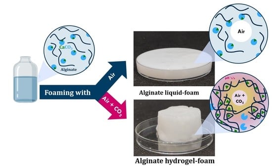
One-Step Generation of Alginate-Based Hydrogel Foams Using CO2 for Simultaneous Foaming and Gelation

by
Imene Ben Djemaa
1,2,
Sébastien Andrieux
1,
Stéphane Auguste
2,
Leandro Jacomine
1,
Malgorzata Tarnowska
2 and
Wiebke Drenckhan-Andreatta
1,*
1
Institut Charles Sadron, CNRS UPR22-University of Strasbourg, 67084 Cedex 2 Strasbourg, France
2
Urgo Research Innovation and Development, 21300 Cedex Chenôve, France
*
Author to whom correspondence should be addressed.
Gels 2022, 8(7), 444; https://doi.org/10.3390/gels8070444
Submission received: 16 May 2022 / Revised: 16 June 2022 / Accepted: 22 June 2022 / Published: 16 July 2022
(This article belongs to the Special Issue Biopolymers-Based Emulsions and Hydrogels)

Abstract

:
The reliable generation of hydrogel foams remains a challenge in a wide range of sectors, including food, cosmetic, agricultural, and medical applications. Using the example of calcium alginate foams, we introduce a novel foam generation method that uses CO2 for the simultaneous foaming and pH reduction of the alginate solution to trigger gelation. We show that gelled foams of different gas fractions can be generated in a simple one-step process. We macroscopically follow the acidification using a pH-responsive indicator and investigate the role of CO2 in foam ageing via foam stability measurements. Finally, we demonstrate the utility of interfacial rheology to provide evidence for the gelation process initiated by the dissolution of the CO2 from the dispersed phase. Both approaches, gas-initiated gelation and interfacial rheology for its characterization, can be readily transferred to other types of gases and formulations.

Graphical Abstract

1. Introduction

Hydrogel foams are very attractive for biomedical [1,2,3,4,5], cosmetic [6], food [7], and agricultural applications [8] thanks to their absorption capacity, low density, large surface-to-volume ratio, biocompatibility, and mechanical properties. Since they are obtained by the gelling of an initially liquid foam via a method called “liquid foam templating” [9,10,11], a reliable foam generation process requires the fine-tuning of a wide range of interrelated timescales: foaming time, gelation time, and foam ageing time. For example, overly rapid gelation alters the rheological properties of the foaming liquid during foaming, leading to an inhomogeneous foam, while excessively slow gelation leads to foam collapse before solidification [11].
Special attention has been paid to alginate-based hydrogel foams on the basis of their biocompatibility and their interesting ion-bonding properties [8,12,13,14]. Most alginate hydrogels are physically cross-linked with multivalent-cations, the most popular being calcium-cross-linked alginates [15,16,17,18,19,20,21,22]. However, the external gelation of alginate solution by direct contact with calcium chloride tends to be too rapid to allow for the homogeneous mixing of calcium and alginate solutions, leading to hydrogels with structural heterogeneity and limited mechanical properties [23]. The external gelation of foamed alginate solutions imposes even more constraints on calcium diffusion, increasing the risk of gel heterogeneity [20]. To overcome this drawback, several studies have used microfluidics to generate alginate bubbles one by one and collect them in a calcium chloride solution [21,22]. However, microfluidics is limited by its low production rate [24]. A more efficient method for the cross-linking of alginates is internal cross-linking: using either the pH-dependent solubility of solid calcium-based salts (e.g., CaCO3) [17,25] or the pH-triggered release of calcium ions complexed with a chelating agent [26]. In both cases, gelation is initiated by the acidification of the alginate solution mixed with calcium in its inactive form. We shall call the solution of dissolved sodium alginate mixed with CaCO3 the “pre-gelling solution”. This method provides access to a wider range of foaming methods, including chemical foaming [15] and mechanical foaming [17,19,27,28,29,30]. Acidification is commonly ensured using glucono-delta-lactone (GDL), a compound which slowly hydrolyzes to release gluconic acid, leading to a slow decrease in pH, and, in turn, a slow and homogeneous release of calcium ions for cross-linking [23]. However, since GDL starts hydrolyzing as soon as it is dissolved, the kinetics of acidification, and therefore gelation, are closely linked with the kinetics of the dissolution and hydrolysis of GDL. Moreover, to generate hydrogel foams, the GDL needs to be added as a powder prior to foaming, which adds a strong constraint on the foaming time and limits the range of applicable foaming methods. An efficient technique for internal gelation applicable to a wide range of foaming methods is therefore still lacking.
To fill this gap, we introduce here an innovative approach which couples foaming and the triggering of gelation in a one-step process [31] by mechanical foaming with an air-CO2 mixture (Figure 1). The diffusion and dissolution of the CO2 from the foam bubbles into the alginate solution induces the interface-driven acidification of the initially basic pre-gelling solution via the following equilibria [32]:
CO2(g) ⇋ CO2(aq)
CO2(aq) + 2 H2O ⇌ H2CO3 + H2O ⇋ HCO3 + H3O+
HCO3 + H2O ⇌ CO32− + H3O+.
This acidification induces the progressive release of the calcium ions around the bubbles and hence the homogeneous gelation of the overall foam. We show that the gelation process from the interface into the bulk of the continuous phase efficiently protects the foam from all relevant foam ageing mechanisms, leading to a stable hydrogel foam (Section 2.1). We furthermore introduce interfacial rheology as a convenient tool to monitor the gas-driven gelation process of an isolated interface (Section 2.2).

2. Results and Discussion

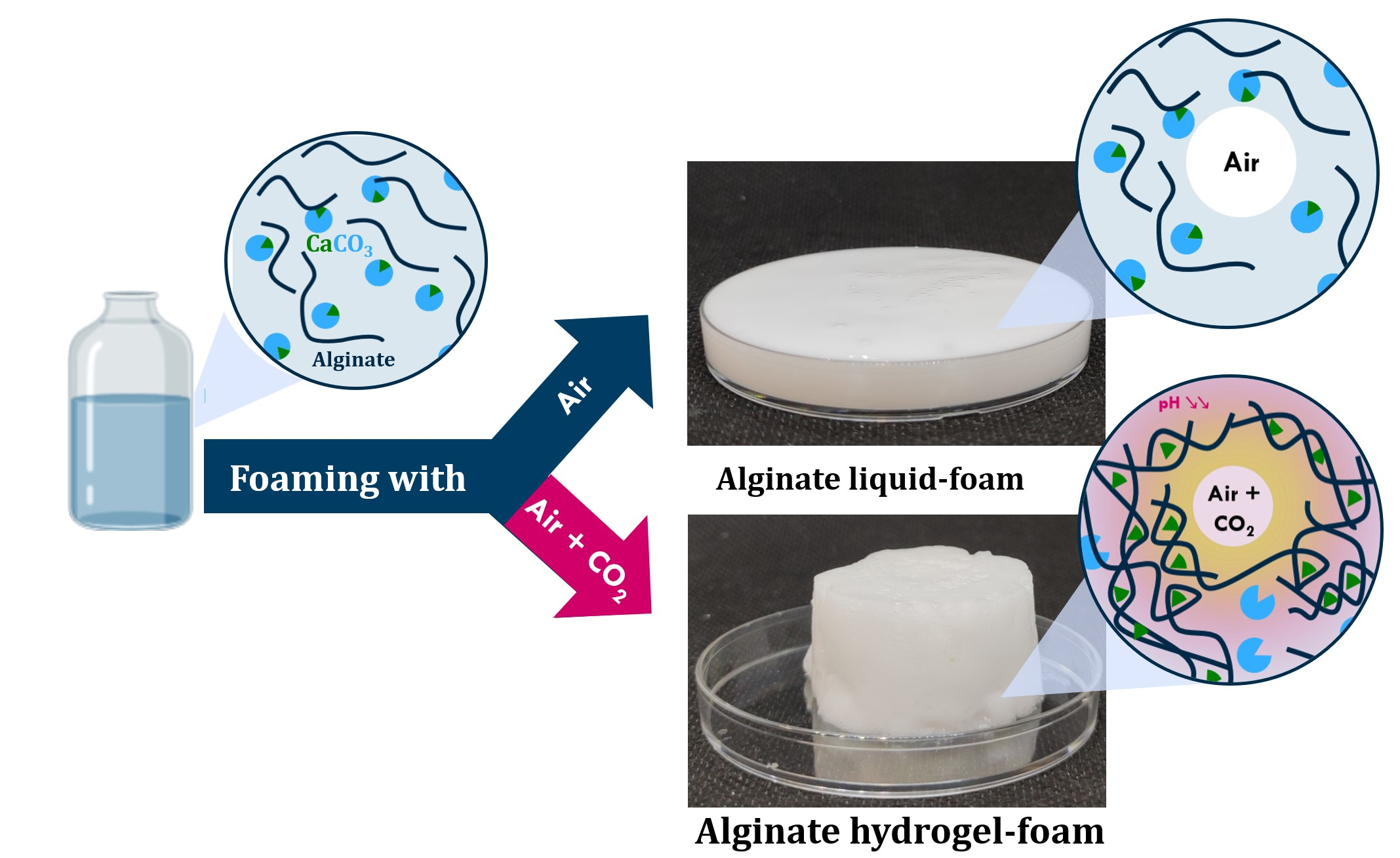
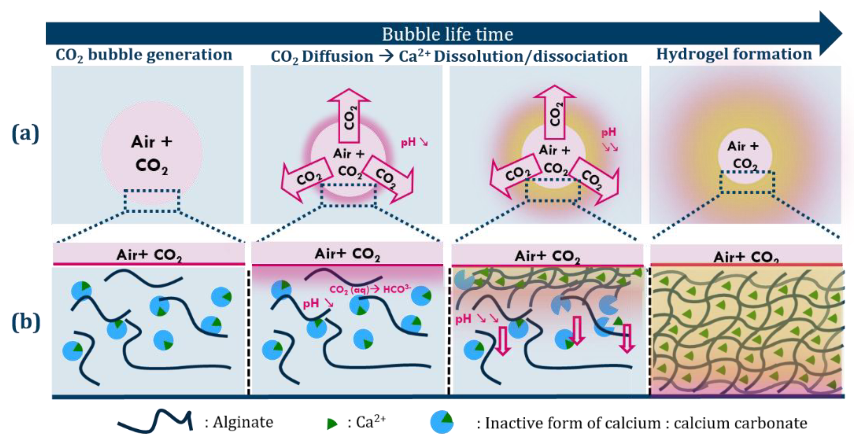
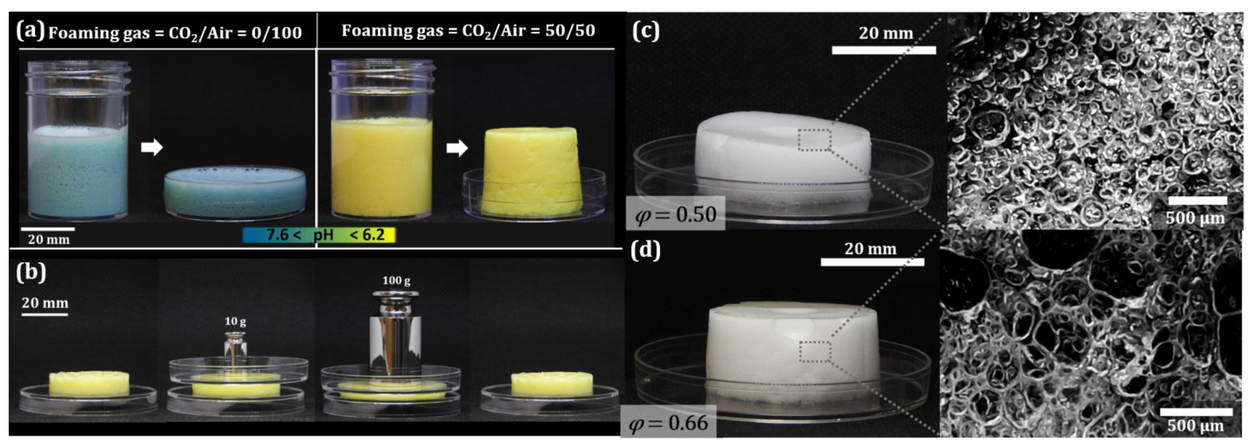
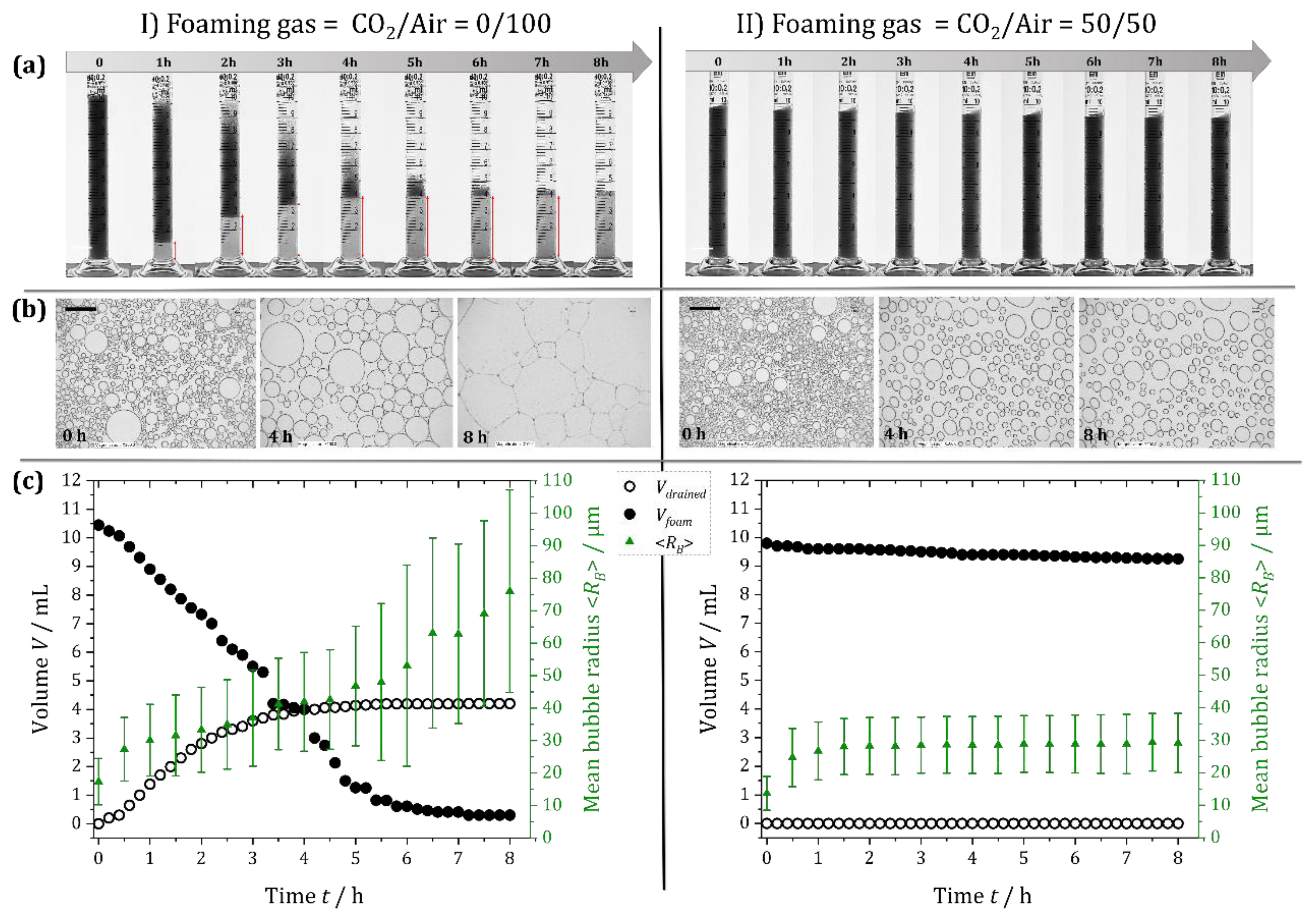
2.1. Foam-Scale Investigation of CO2 Effect on Alginate Foam Gelation

We produced foams with different gas fractions, φ (ratio of gas volume to foam volume), and CO2/air ratios using the double syringe technique (Section 4.2.1). The foaming solutions contained 1 wt% alginate and 0.2 M calcium carbonate microparticles (Section 4.1). In some cases, bromothymol blue was added as a pH indicator to observe the evolution of the pH following foaming. Since this dye reveals pH changes in the range between 6.2 (yellow) and 7.6 (blue) [33], the solution was blue (pH 10) before foaming.
Figure 2a (left) shows a foam generated with air as the foaming gas. The foam retained its initial blue color, i.e., the pH remained > 7.6 after foaming. Because the foam remained liquid, it could be poured from the container into a petri dish. However, a foam formed with a CO2/air volume ratio of 50/50 (Figure 2a, right) changed color from blue to yellow within a few seconds, revealing a rapid pH decrease down to ≤ 6.2. This pH corresponds to the pH of the maximum release of Ca2+ from CaCO3, as confirmed by ionometry (Section 6 in the supplementary materials). This foam retained the cylindrical shape of the vial after it was removed. When subjected to a force exerted by weights (Figure 2b), it demonstrated resistance to compression, confirmed by the fact that its shape returned to its initial form after the weight was removed (Figure 2b, right). The weight–deformation relation of this simple experiment allowed us to estimate that the Young’s modulus of the foam was about 1.4 kPa and that of the gel was about 13 kPa (Section 5 in the supplementary materials). Incorporating CO2 into the foaming gas thus led to the acidification and gelation of the foam.
The morphology of the obtained hydrogel foams could be controlled via the gas fraction φ. Figure 2c,d show two examples at a CO2/air volume ratio of 50/50: The foam in Figure 2c was generated with φ = 0.5, while the foam in Figure 2d was prepared with φ = 0.66. One can see from the microscope images that the bubbles in the foam with φ = 0.66 (Figure 2d) are deformed into polyhedral shapes [34,35], while the bubbles in the foam with φ = 0.5 remain fairly spherical and are not in contact with each other, indicating a morphology closer to a “bubbly hydrogel” than a foam.
To quantitatively investigate the effect of the addition of CO2 on the foam stability, we compared the ageing of a foam generated with air (CO2/air = 0/100) to that of a foam obtained with CO2/air = 50/50 (Section 4.2.1).
The foam generated with CO2/air = 0/100 showed the classic features of an unstable foam [35]: an increasing volume of liquid, Vdrained, drained out of the foam under the action of gravity (transparent zone underneath the foam in Figure 3Ia and Vdrained in Figure 3Ic), and the overall foam volume, Vfoam, decreased with time due to the coalescence of bubbles from the top of the foam (Figure 3Ia and Vfoam in Figure 3Ic). Moreover, coalescence and gas exchange between bubbles led to a progressive increase in the mean bubble radius <RB> with time (green data in Figure 3Ic). The combination of all these mechanisms led to the progressive disappearance of the foam over the 8 h of observation.
We observed very different behavior for the foam generated with the CO2/air = 50/50 mixture. As shown in Figure 3IIa,c, the drainage of the liquid was completely stopped from the outset, which can be attributed to the rapid gelation of the continuous phase. Moreover, the foam height remained constant, indicating the absence of bubble coalescence from the top of the foam. Nevertheless, the average bubble radius <RB> evolved over the first hour due to the CO2 dissolution and gas exchange between bubbles driven by the difference in the Laplace pressure between bubbles of different sizes. This evolution stopped when the liquid is saturated with CO2 and when the elastic modulus of the continuous phase was high enough to counteract the driving pressure difference [36].
While the reported observations clearly prove the gelation of the foam thanks to the CO2, future investigations should establish more quantitatively the influence of the CO2 content, gas fraction φ, bubble size RB, and alginate concentration on the gelation kinetics and associated foam stability, as has been achieved in the past for gelatin foams [36].

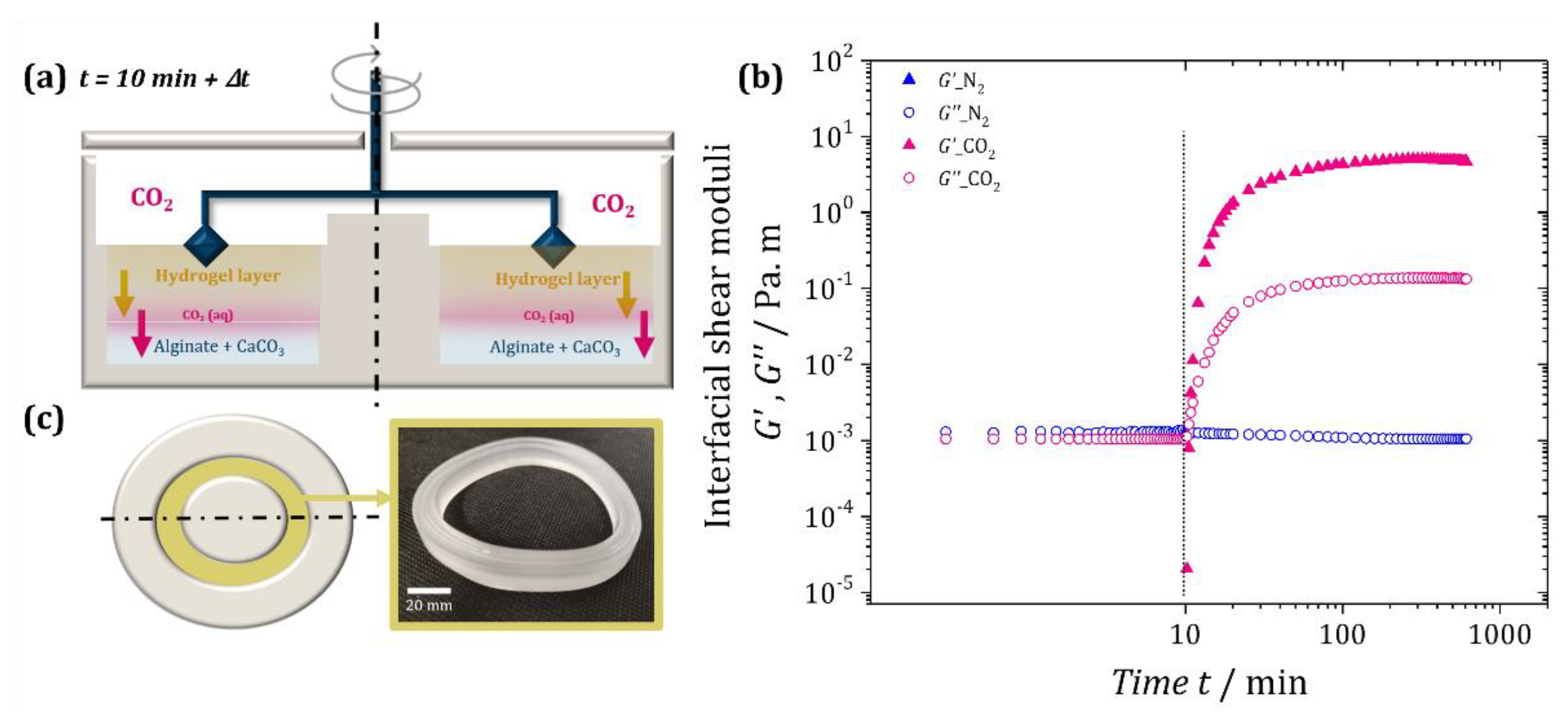
2.2. Interfacial Investigation of CO2 Effect on Alginate Gelation

To obtain a more quantitative characterization of the interface-driven CO2-induced gelation, we characterized the interfacial properties of the alginate solution mixed with calcium carbonate microparticles using interfacial shear rheology in the absence and presence of CO2 (Section 4.2.2). The double-wall ring geometry [37] of the setup is sketched in Figure 4a.
Figure 4b shows the evolution of the interfacial elastic and loss modulus, G′ and G″, respectively, over time for the two experiments. During the first 10 min under ambient air, the interfacial elastic modulus G′ was below the measurement threshold, while the interfacial loss modulus G″ was about 10−3 Pa m. This is characteristic of purely viscous interfaces [38,39]. Most importantly, the measured values remained constant over the 10 min under an airflow, indicating the absence of gelation. After switching on the N2 flow (blue curve after the vertical line, Figure 4b), G′ remained below the detection limit and the interfacial loss modulus G″ also remained nearly constant. Therefore, the interface remained in a purely viscous state, indicating that the N2 flow did not trigger gelation. This was very different when the CO2 flow was switched on (pink curve after vertical line, Figure 4b). Both the interfacial elastic and loss modulus increased rapidly, with the elastic modulus G′ exceeding the loss modulus G″ after less than a minute (G′ > G″). This indicated a sol–gel transition [39,40,41] caused by the progressive gelation of the alginate starting from the liquid/gas interface, as sketched in Figure 4a. As the gelling front progressed into the solution upon the dissolution/diffusion of CO2, both G′ and G″ kept increasing until a plateau was reached after ca. 100 min. Since alginate hydrogels are reported in the literature to have mesh sizes in the range of 7–20 nm [42,43,44], much larger than the diameter of a CO2 molecule (0.33 nm), we may consider that the diffusion/dissolution of CO2 remained unhindered by the hydrogel formation. Hypothesizing a diffusion-limited process with a diffusion constant of D = 1.89 × 10⁻⁹ m2/s (at 1 atm and 25 °C) for CO2 in water [45] (which we confirm in Section 1 in the supplementary materials), we can then estimate that at t = 100 min, the CO2 had penetrated roughly L = (6Dt)1/2 ≈ 8 mm into the liquid. This means that it is likely that the acidification and the gelation front had reached the bottom of the trough (10 mm), which may explain the plateau. This hypothesis is also supported by the fact that the gel at the end of the experiment could be removed in one solid piece from the trough, as shown in Figure 4c. The obtained bulk hydrogel suggests that CO2 introduction via gas flow above the solution may also be an interesting method for formulating bulk hydrogels using CO2 instead of other acids.
We can use the same estimations as above to approximate the characteristic gelation time of the foams (see Figure S1). Considering a foam with an average bubble radius of <RB> = 100 µm and nearly spherical bubbles, we can estimate that the liquid zones between the bubbles have approximately the same characteristic thickness [35]. Hence, it will take about t = (100 µm)2/(6D) ≈ 1 s for the CO2 to diffuse into the continuous phase of the foam. This calculation also agrees with the interfacial rheology experiment (Figure 4b), in which the viscoelastic moduli of the interface evolved dramatically over the first few seconds of CO2 flow. Interfacial rheology therefore constitutes a promising method for the characterization of interface-induced gelation and could easily be applied to other systems with interface-triggered solidification. However, a truly quantitative interpretation of the viscoelastic moduli requires appropriate modelling of the gelation process and the modification of the analysis software of the rheometer, since the current tool was developed for nano- to micrometer-thick interfacial layers in contact with a homogeneous liquid of constant viscosity. In our gelation experiments, this holds true only for the very first instances. Hence, the quantitative values from more than a few seconds after switching on the CO2 flow should only be taken as indicators.

3. Conclusions

In summary, we reported for the first time the generation of alginate-based hydrogel foams using the foaming gas as the gelation trigger in a simple one-step process. We showed that foaming with a gas mixture containing CO2 allowed the acidification and thus the gelation of the continuous phase and efficiently stopped all the main mechanisms of foam ageing. The different timescales of the foaming/gelation process and the final foam properties could be adjusted via the CO2 fraction of the foaming gas and the gas fraction (φ) of the initially liquid foam. Here, we focused on a general introduction to the method to show its feasibility. Different physico-chemical and physical parameters are involved in this system whose quantitative influence remains to be established via a fully systematic approach. The physico-chemical parameters include the structural properties of the sodium alginate (its molecular weight and its mannuronic-acid-to-guluronic-acid ratio); its concentration; the concentration of CaCO3; the choice of the surfactant; the CO2/air ratio; and the use of additives. The physical parameters include the bubble size and the gas fraction. These parameters are largely interconnected, requiring in-depth investigation, ideally coupled with an analysis of the final foam in terms of its mechanical properties.
We also showed that the characteristic timescales and evolution of the mechanical properties of the interface-driven gelation can be demonstrated using interfacial shear rheology—even though a fully quantitative interpretation of the obtained values requires the adaptation of the analysis algorithms.
It needs to be kept in mind that for the gelled foams to remain stable, they have to be contained in a sealed environment, since otherwise, the CO2 will slowly leave the foam. This will lead to a progressive increase in the pH and hence a progressive “degelling” of the foam matrix, which will render the foam sensitive again to the different ageing mechanisms, leading to its final destruction. The duration of this gelation–degelation cycle can be controlled by the initial CO2 content, gas fraction (φ), bubble size (RB), and alginate type/concentration. It may therefore be of interest for processes wherein a highly stable (gelled) foam is only needed for a specific period of time.
Last but not least, both foaming and interfacial rheology can easily be extended to other pH-sensitive polymers or proteins [46,47,48,49,50] (and potentially to other water-soluble gas components). We therefore believe that our findings may inspire much wider activities pertaining to gas-initiated material fabrication.

4. Materials and Methods

4.1. Materials

We used a pre-gelling solution of 1 wt% alginic acid sodium salt (purchased from Alfa Aesar), which was solubilized in Milli-Q water under mechanical stirring at 50 °C for 3 h. We dispersed 0.02 M of calcium carbonate microparticles with an average size of 5 µm (purchased from Alfa Aesar) in the alginate solution by magnetic mixing for 30 min together with 2 wt% of the surfactant Disponil APG 425 (an alkyl polyglycoside, from BASF). The initial pH of this solution was 10. All solutions were prepared in contact with air and were therefore considered to be in equilibrium with the natural CO2 content of air (~0.04%) before and after foaming with air.
In some cases, 5 × 10⁻⁵ M of bromothymol blue was added to the solution (with calcium bicarbonate salt) as the pH-sensitive indicator. This dye reveals pH changes in the range between 6.2 (yellow) and 7.6 (blue) [33]. The foaming solution was therefore blue before foaming.

4.2. Methods

4.2.1. Foaming and Foam Ageing Analysis

We produced the foams using the double-syringe technique [51](see Figure S2), which consists of mixing the foaming solution with the selected gas mixture by repeatedly pushing the gas/liquid mixture from one syringe to another (4 cycles) for ca. 10 s. The overall gas fraction φ (gas volume/foam volume) of the initially liquid foam was controlled by how much gas was added to the syringes with respect to the liquid volume. The final gas fraction of the hydrogel foam was slightly smaller, since some of the CO2 dissolved in the liquid. Gas mixtures with particular CO2/air volume ratios were prepared by filling the syringe first with a given volume of CO2, collected above dry ice, to which a given volume of air was added at ambient pressure.
The generated foams were collected in graduated cylinders of 12 mm internal diameter, and their evolution over time was captured using a digital camera over eight hours following their generation. In parallel, we squeezed part of the foam between two sealed glass plates separated by 34 µm to create a monolayer of bubbles (see Figure S3) for the easier characterization of the evolution of the mean bubble radius <RB>.

4.2.2. Interfacial Shear Rheology

The interfacial shear rheology experiments were conducted using a DHR-3 rheometer (TA instruments) with a double-wall ring (DWR) geometry [37,52] and the same pre-gelling solutions as were used for the foaming experiments, though without surfactant to avoid interferences related to the viscoelastic properties of the surfactant monolayer.
To obtain the viscoelastic moduli of the interface, the ring was oscillated at a frequency of 0.2 Hz and a strain amplitude of 1%. After 10 min of measurement in ambient air, a controlled gas flow was generated above the liquid using either N2 from a compressed gas bottle or CO2 collected above dry ice in an ice-bathed steel bottle. The gas passed through a flowmeter set at 150 mL/min and was humidified by bubbling through water previously saturated with N2 or CO2, respectively (see Figure S4). This humidification was important to prevent the drying of the liquid surface due to the gas flows, which could be misinterpreted as gelation.

Supplementary Materials

The following supporting information can be downloaded at: https://www.mdpi.com/article/10.3390/gels8070444/s1, Figure S1. (a) The evolution of the diffusion length (L) of aqueous CO2 dissolved from a bubble of radius 2.2 mm. The line is the theoretical prediction using the well-known diffusion constant of D = 1.89 × 10⁹ m2/s for CO2 in water (at 1 atm and 25° C). (b) Selected images of the bubble (black circle and the surrounding ring) with the propagating CO2 front (dark region) taken at t = 0 s, t = 20 s, t = 40 s, and t = 60 s; Figure S2. Setup for double-syringe foaming technique; Figure S3. Left—Setup for obtaining a monolayer of foam. Right—Steps for image treatment using ImageJ: (a) the original image recorded by microscope, (b) conversion to binary image (8 bits), (c) thresholding, (d) automatic detection of circular objects and area measurement [51]; Figure S4. Top—Setups for introducing (a) CO2 or (b) N2 flow into the rheometer. The central picture shows a zoom-in on the double-wall ring (DWR) geometry used for this experiment, in which the sample was loaded. Bottom—Schematic drawings of the corresponding setups; Figure S5. Left: Simple compression tests on a hydrogel foam obtained by foaming a mixture of 1 wt% alginate, 0.02 M CaCO3, 2 wt% Disponil APG 425, and 5 × 10⁻⁵ M bromothymol with CO2/air = 50/50. Right: Obtained values of the applied stresses as a function of the resulting de-formation with a linear fit [36,53]; Figure S6. Amplitude sweep test on a hydrogel (1 wt% alginate, 0.02 M CaCO3, 1 wt%) gelled using GDL instead of CO2. Figure S7. Percentage of released calcium ions from CaCO3 as a function of pH.

Author Contributions

Conceptualization, I.B.D., S.A. (Stéphane Auguste), M.T., W.D.-A., and S.A. (Sébastien Andrieux); methodology, I.B.D., L.J., W.D.-A., and S.A. (Sébastien Andrieux); validation, I.B.D., L.J., W.D.-A., and S.A. (Sébastien Andrieux); formal analysis, I.B.D. and L.J.; investigation, I.B.D. and L.J.; resources, S.A. (Stéphane Auguste) and W.D.-A.; data curation, I.B.D. and L.J.; writing—original draft preparation, I.B.D., W.D.-A. and S.A. (Sébastien Andrieux); writing—review and editing, I.B.D., S.A. (Stéphane Auguste), L.J., M.T., W.D.-A., and S.A. (Sébastien Andrieux); visualization, I.B.D.; supervision, W.D.-A. and S.A. (Sébastien Andrieux); project administration, S.A. (Stéphane Auguste) and W.D.-A.; funding acquisition, S.A. (Stéphane Auguste) and W.D.-A. All authors have read and agreed to the published version of the manuscript.

Funding

This work was conducted in the framework of an ERC consolidator grant (agreement 819511—ETAFOAM) and a collaboration with URGO, supported by CIFRE ANRT (agreement n° 2019/1150). This work of the Interdisciplinary Institute HiFunMat, as part of the ITI 2021-2028 program of the University of Strasbourg, CNRS, and Inserm, was supported by IdEx Unistra (ANR-10-IDEX-0002) and SFRI (STRAT’US project, ANR-20-SFRI-0012) under the framework of the French Investments for the Future Program.

Acknowledgments

The authors acknowledge many fruitful discussions with Laurent Apert, François Schosseler, and the Algaia team.

Conflicts of Interest

The authors declare no conflict of interest.

References

  1. Baxter, J.; Lima, T.A.; Huneke, R.; Kanach, C.J.; Johal, P.; Reimold, E.; Alvarez, N.J.; Laub, G.W. The Efficacy of Hydrogel Foams in Talc Pleurodesis. J. Cardiothorac. Surg. 2020, 15, 58. [Google Scholar] [CrossRef] [PubMed] [Green Version]
  2. Conley Wake, M.; Mikos, A.G.; Sarakinos, G.; Vacanti, J.P.; Langer, R. Dynamics of Fibrovascular Tissue Ingrowth in Hydrogel Foams. Cell Transplant. 1995, 4, 275–279. [Google Scholar] [CrossRef]
  3. Andersen, T.; Markussen, C.; Dornish, M.; Heier-Baardson, H.; Melvik, J.E.; Alsberg, E.; Christensen, B.E. In Situ Gelation for Cell Immobilization and Culture in Alginate Foam Scaffolds. Tissue Eng. Part A 2014, 20, 600–610. [Google Scholar] [CrossRef] [PubMed] [Green Version]
  4. Raya, B.; Caroline, C.; Christophe, T.; Benjamin, D.; Philippe, B.; Daniel, C.; Angelo, P.; Brigitte, S.; Sophie, G.F. Design of Biopolymer-Based 3D Scaffolds for Cardiac Mesenchymal Stem Cell Therapy. Front. Bioeng. Biotechnol. 2016. [Google Scholar] [CrossRef]
  5. Aminabhavi, T.M.; Deshmukh, A.S. Polymeric Hydrogels as Smart Biomaterials; Springer: Berlin, Germany, 2016; ISBN 978-3-319-25320-6. [Google Scholar]
  6. Arzhavitina, A.; Steckel, H. Foams for Pharmaceutical and Cosmetic Application. Int. J. Pharm. 2010, 394, 1–17. [Google Scholar] [CrossRef]
  7. Ma, L.; Li, Q.; Du, Z.; Su, E.; Liu, X.; Wan, Z.; Yang, X. A Natural Supramolecular Saponin Hydrogelator for Creation of Ultrastable and Thermostimulable Food-Grade Foams. Adv. Mater. Interfaces 2019, 6, 1900417. [Google Scholar] [CrossRef]
  8. Rizwan, M.; Rubina Gilani, S.; Iqbal Durani, A.; Naseem, S. Materials Diversity of Hydrogel: Synthesis, Polymerization Process and Soil Conditioning Properties in Agricultural Field. J. Adv. Res. 2021, 33, 15–40. [Google Scholar] [CrossRef]
  9. Stubenrauch, C.; Menner, A.; Bismarck, A.; Drenckhan, W. Emulsion and Foam Templating-Promising Routes to Tailor-Made Porous Polymers. Angew. Chemie Int. Ed. 2018, 57, 10024–10032. [Google Scholar] [CrossRef]
  10. Andrieux, S.; Quell, A.; Stubenrauch, C.; Drenckhan, W. Liquid Foam Templating – A Route to Tailor-Made Polymer Foams. Adv. Colloid Interface Sci. 2018, 256, 276–290. [Google Scholar] [CrossRef]
  11. BenDjemaa, I.; Auguste, S.; Drenckhan-Andreatta, W.; Andrieux, S. Hydrogel Foams from Liquid Foam Templates: Properties and Optimisation. Adv. Colloid Interface Sci. 2021, 294, 102478. [Google Scholar] [CrossRef]
  12. Lee, K.Y.; Mooney, D.J. Alginate: Properties and Biomedical Applications. Prog. Polym. Sci. 2012, 37, 106–126. [Google Scholar] [CrossRef] [PubMed] [Green Version]
  13. BeMiller, J. Carbohydrate Chemistry for Food Scientists; Elsevier: Amsterdam, The Netherlands, 2018. [Google Scholar]
  14. Grant, G.T.; Morris, E.R.; Rees, D.A.; Smith, P.J.C.; Thom, D. Biological Interactions between Polysaccharides and Divalent Cations: The Egg-Box Model. FEBS Lett. 1973, 32, 195–198. [Google Scholar] [CrossRef] [Green Version]
  15. Catanzano, O.; Soriente, A.; La Gatta, A.; Cammarota, M.; Ricci, G.; Fasolino, I.; Schiraldi, C.; Ambrosio, L.; Malinconico, M.; Laurienzo, P.; et al. Macroporous Alginate Foams Crosslinked with Strontium for Bone Tissue Engineering. Carbohydr. Polym. 2018, 202, 72–83. [Google Scholar] [CrossRef]
  16. Cole, S.M.; Garbe, J.E.; Woodson, L.P. Water-Insoluble Polysaccharide Hydrogel Foam for Medical Applications U.S. Patent 5,089,606, 18 February 1992.
  17. Andersen, T.; Melvik, J.E.; Gåserød, O.; Alsberg, E.; Christensen, B.E. Ionically Gelled Alginate Foams: Physical Properties Controlled by Type, Amount and Source of Gelling Ions. Carbohydr. Polym. 2014, 99, 249–256. [Google Scholar] [CrossRef] [PubMed]
  18. Ceccaldi, C.; Bushkalova, R.; Cussac, D.; Duployer, B.; Tenailleau, C.; Bourin, P.; Parini, A.; Sallerin, B.; Girod Fullana, S.; Fullana, G.; et al. Elaboration and Evaluation of Alginate Foam Scaffolds for Soft Tissue Engineering. Int. J. Pharm. 2017, 524, 433–442. [Google Scholar] [CrossRef] [PubMed] [Green Version]
  19. Andersen, T.; Melvik, J.E.; Gåserød, O.; Alsberg, E.; Christensen, B.E. Ionically Gelled Alginate Foams: Physical Properties Controlled by Operational and Macromolecular Parameters. Biomacromolecules 2012, 13, 3703–3710. [Google Scholar] [CrossRef] [PubMed]
  20. Chung, K.; Mishra, N.C.; Wang, C.; Lin, F.; Lin, K. Fabricating Scaffolds by Microfluidics. Biomicrofluidics 2009, 3, 22403. [Google Scholar] [CrossRef] [Green Version]
  21. Wang, C.-C.; Yang, K.-C.; Lin, K.-H.; Liu, H.-C.; Lin, F.-H. A Highly Organized Three-Dimensional Alginate Scaffold for Cartilage Tissue Engineering Prepared by Microfluidic Technology. Biomaterials 2011, 32, 7118–7126. [Google Scholar] [CrossRef]
  22. Ahmad, B.; Stride, E.; Edirisinghe, M. Calcium Alginate Foams Prepared by a Microfluidic T-Junction System: Stability and Food Applications. Food Bioprocess Technol. 2012, 5, 2848–2857. [Google Scholar] [CrossRef]
  23. Kuo, C.K.; Ma, P.X. Ionically Crosslinked Alginate Hydrogels as Scaffolds for Tissue Engineering: Part 1. Structure, Gelation Rate and Mechanical Properties. Biomaterials 2001, 22, 511–521. [Google Scholar] [CrossRef]
  24. Wang, B.; Prinsen, P.; Wang, H.; Bai, Z.; Wang, H.; Luque, R.; Xuan, J. Macroporous Materials: Microfluidic Fabrication, Functionalization and Applications. Chem. Soc. Rev. 2017, 46, 855–914. [Google Scholar] [CrossRef] [PubMed] [Green Version]
  25. Draget, K.I.; Østgaard, K.; Smidsrød, O. Homogeneous Alginate Gels: A Technical Approach. Carbohydr. Polym. 1990, 14, 159–178. [Google Scholar] [CrossRef]
  26. Liu, X.; Qian, L.; Shu, T.; Tong, Z. Rheology Characterization of Sol–Gel Transition in Aqueous Alginate Solutions Induced by Calcium Cations through in Situ Release. Polymer 2003, 44, 407–412. [Google Scholar] [CrossRef]
  27. Nilsen-Nygaard, J.; Hattrem, M.N.; Draget, K.I. Propylene Glycol Alginate (PGA) Gelled Foams: A Systematic Study of Surface Activity and Gelling Properties as a Function of Degree of Esterification. Food Hydrocoll. 2016, 57, 80–91. [Google Scholar] [CrossRef]
  28. Valerón Bergh, V.J.; Johannessen, E.; Andersen, T.; Tønnesen, H.H. Evaluation of Porphyrin Loaded Dry Alginate Foams Containing Poloxamer 407 and β-Cyclodextrin-Derivatives Intended for Wound Treatment. Pharm. Dev. Technol. 2018, 23, 761–770. [Google Scholar] [CrossRef] [PubMed]
  29. Vincent, T.; Ic Dumazert, L.; Dufourg, L.; Cucherat, C.; Sonnier, R.; Guibal, E. New Alginate Foams: Box-Behnken Design of Their Manufacturing; Fire Retardant and Thermal Insulating Properties. J. Appl. Polym. Sci 2017, 135, 45868. [Google Scholar] [CrossRef]
  30. Vincent, T.; Vincent, C.; Dumazert, L.; Otazaghine, B.; Sonnier, R.; Guibal, E. Fire Behavior of Innovative Alginate Foams. Carbohydr. Polym. 2020, 250, 116910. [Google Scholar] [CrossRef] [PubMed]
  31. Ginot, G.; Höhler, R.; Mariot, S.; Kraynik, A.; Drenckhan-Andreatta, W. Juggling bubbles in square capillaries: An experimental proof of non-pairwise bubble interactions. Soft Matter 2019, 15, 4570–4582. [Google Scholar]
  32. Meyssami, B.; Balaban, M.O.; Teixeira, A.A. Prediction of PH in Model Systems Pressurized with Carbon Dioxide. Biotechnol. Prog. 1992, 8, 149–154. [Google Scholar] [CrossRef]
  33. Puschett, J.B.; Rao, B.S.; Karandikar, B.M.; Matyjaszewski, K. Indicator Characteristics of Bromothymol Blue Derivatives. Talanta 1991, 38, 335–338. [Google Scholar] [CrossRef]
  34. Siemens, A.O.N.; Van Hecke, M. Jamming: A Simple Introduction. Phys. A Stat. Mech. its Appl. 2010, 389, 4255–4264. [Google Scholar] [CrossRef]
  35. Cantat, I.; Cohen-Addad, S.; Elias, F.; Graner, F.F.F.; Höhler, R.; Pitois, O.; Rouyer, F.; Saint-Jalmes, A.; HÖhler, R.; Pitois, O.; et al. Foams: Structure and Dynamics; Cox, S.J., Ed.; Oxford University Press: Oxford, UK, 2013; ISBN 9780199662890. [Google Scholar]
  36. Bey, H.; Wintzenrieth, F.; Ronsin, O.; Höhler, R.; Cohen-Addad, S. Stabilization of Foams by the Combined Effects of an Insoluble Gas Species and Gelation. Soft Matter 2017, 13, 6816–6830. [Google Scholar] [CrossRef] [PubMed] [Green Version]
  37. Vandebril, S.; Franck, A.; Fuller, G.G.; Moldenaers, P.; Vermant, J. A Double Wall-Ring Geometry for Interfacial Shear Rheometry. Rheol. Acta 2010, 49, 131–144. [Google Scholar] [CrossRef]
  38. Krägel, J.; Derkatch, S.R. Interfacial Shear Rheology. Curr. Opin. Colloid Interface Sci. 2010, 15, 246–255. [Google Scholar] [CrossRef]
  39. Fuller, G.G.; Vermant, J. Complex Fluid-Fluid Interfaces: Rheology and Structure. Annu. Rev. Chem. Biomol. Eng. 2012, 3, 519–543. [Google Scholar] [CrossRef] [PubMed]
  40. Tung, C.M.; Dynes, P.J. Relationship between Viscoelastic Properties and Gelation in Thermosetting Systems. J. Appl. Polym. Sci. 1982, 27, 569–574. [Google Scholar] [CrossRef]
  41. Rehage, H.; Husmann, M.; Walter, A. From Two-Dimensional Model Networks to Microcapsules. Rheol. Acta 2002 414 2002, 41, 292–306. [Google Scholar] [CrossRef]
  42. Turco, G.; Donati, I.; Grassi, M.; Marchioli, G.; Lapasin, R.; Paoletti, S. Mechanical Spectroscopy and Relaxometry on Alginate Hydrogels: A Comparative Analysis for Structural Characterization and Network Mesh Size Determination. Biomacromolecules 2011, 12, 1272–1282. [Google Scholar] [CrossRef]
  43. Grassi, M.; Sandolo, C.; Perin, D.; Coviello, T.; Lapasin, R.; Grassi, G. Structural Characterization of Calcium Alginate Matrices by Means of Mechanical and Release Tests. Molecules 2009, 14, 3003–3017. [Google Scholar] [CrossRef] [Green Version]
  44. Yang, C.; Suo, Z. Hydrogel Ionotronics. Nat. Rev. Mater. 2018, 3, 125–142. [Google Scholar] [CrossRef]
  45. Peñas-López, P.; Van Elburg, B.; Parrales, M.A.; Rodríguez-Rodríguez, J. Diffusion of Dissolved CO 2 in Water Propagating from a Cylindrical Bubble in a Horizontal Hele-Shaw Cell. APS 2017, 2, 063602. [Google Scholar] [CrossRef] [Green Version]
  46. Montellano Duran, N.; Galante, M.; Spelzini, D.; Boeris, V. The Effect of Carrageenan on the Acid-Induced Aggregation and Gelation Conditions of Quinoa Proteins. Food Res. Int. 2018, 107, 683–690. [Google Scholar] [CrossRef] [PubMed]
  47. De Alcântara, M.G.; de Freitas Ortega, N.; Souza, C.J.F.; Garcia-Rojas, E.E. Electrostatic Hydrogels Formed by Gelatin and Carrageenan Induced by Acidification: Rheological and Structural Characterization. Food Struct. 2020, 24, 100137. [Google Scholar] [CrossRef]
  48. Liu, D.; Zhou, P.; Nicolai, T. Effect of Kappa Carrageenan on Acid-Induced Gelation of Whey Protein Aggregates. Part I: Potentiometric Titration, Rheology and Turbidity. Food Hydrocoll. 2020, 102, 105589. [Google Scholar] [CrossRef]
  49. Agoub, A.A.; Giannouli, P.; Morris, E.R. Gelation of High Methoxy Pectin by Acidification with D-Glucono-δ-Lactone (GDL) at Room Temperature. Carbohydr. Polym. 2009, 75, 269–281. [Google Scholar] [CrossRef]
  50. Cardoso, A.Z.; Alvarez Alvarez, A.E.; Cattoz, B.N.; Griffiths, P.C.; King, S.M.; Frith, W.J.; Adams, D.J. The Influence of the Kinetics of Self-Assembly on the Properties of Dipeptide Hydrogels. Faraday Discuss. 2013, 166, 101–116. [Google Scholar] [CrossRef] [PubMed]
  51. Gaillard, T.; Honorez, C.; Jumeau, M.; Elias, F.; Drenckhan, W. A simple technique for the automation of bubble size measurements. Colloids Surf. A Physicochem. Eng. Asp. 2015, 473, 68–74. [Google Scholar]
  52. Franck, A.; Vermant, J.; Fuller, G.G. System and Method for Interfacial Rheometry. U.S. Patent 7926326B2, 5 March 2009. [Google Scholar]
  53. Gibson, L.J.; Ashby, M.F. Cellular Solids: Structure and Properties, 2nd ed.; Cambridge Solid State Science Series; Cambridge University Press: Cambridge, UK, 1997; ISBN 0521499119,9780521499118. [Google Scholar]
Figure 1. (a) Schematic representation of the internal cross-linking of alginate with inactive calcium ions (CaCO3) via acidification of the medium induced by the dissolution of CO2 from the bubbles. (b) Scheme of the diffusion of CO2 from the interface into the bulk and evolution of the gelling front with time. The growing hydrogel layer is represented in yellow.
Gels 08 00444 g001
Figure 2. Foams obtained with different foaming gases: air (a (left)) vs. CO2/air = 50/50 (a (right),bd). The foaming solution was a mixture of 1 wt% alginate, 0.02 M CaCO3, 2 wt% Disponil APG 425, and 5 × 10⁻⁵ M bromothymol blue as a pH-indicator dye. The morphology of the gelled foams could be controlled via the gas fraction φ: (c) φ = 0.5; (d) φ = 0.66 (both foams generated without pH indicator for better optical contrast).
Gels 08 00444 g002
Figure 3. Foam stability of two alginate foams generated with (I) CO2/air = 0/100 and (II) CO2/air = 50/50. (a) Photographs of the foams taken in closed graduated glass cylinders at 1 h time intervals; the black zone corresponds to the foam, and the transparent zone at the bottom is the drained liquid. (b) Microscope images obtained over 8 h after squeezing the foam into a monolayer of bubbles between two glass plates separated by a 34 µm spacer (scale bars 500 µm). (c) Temporal evolution of the drained volume of liquid, Vdrained, and the foam volume, Vfoam, measured from (a), together with the mean bubble radius measured from (b). The error bars represent the standard deviation of the bubble sizes measured for each image.
Gels 08 00444 g003
Figure 4. (a) Scheme of the double-wall ring (DWR) geometry used for the interfacial shear rheology, showing our understanding of what happens in the presence of CO2: The blue layer at the bottom represents the un-gelled solution (1 wt% alginate, 0.02 M CaCO3). The progressing front of dissolved CO2 (i.e., acidification) is shown in pink, and the progressing gelation front on top in yellow. (b) Temporal evolution of the interfacial elastic shear modulus, G′, and loss modulus, G″, of the gas/liquid surface of the alginate solution when a gas flow of N2 (blue) or CO2 (pink) is switched on after 10 min of exposure to ambient air (vertical line). (c) Hydrogel sample extracted after the experiment using CO2 in the form of a ring maintaining the shape of the geometry.
Gels 08 00444 g004
Publisher’s Note: MDPI stays neutral with regard to jurisdictional claims in published maps and institutional affiliations.

