
Mechanical Properties of 3D Printed Orthodontic Retainers

 , , , ,
Abstract
:1. Introduction
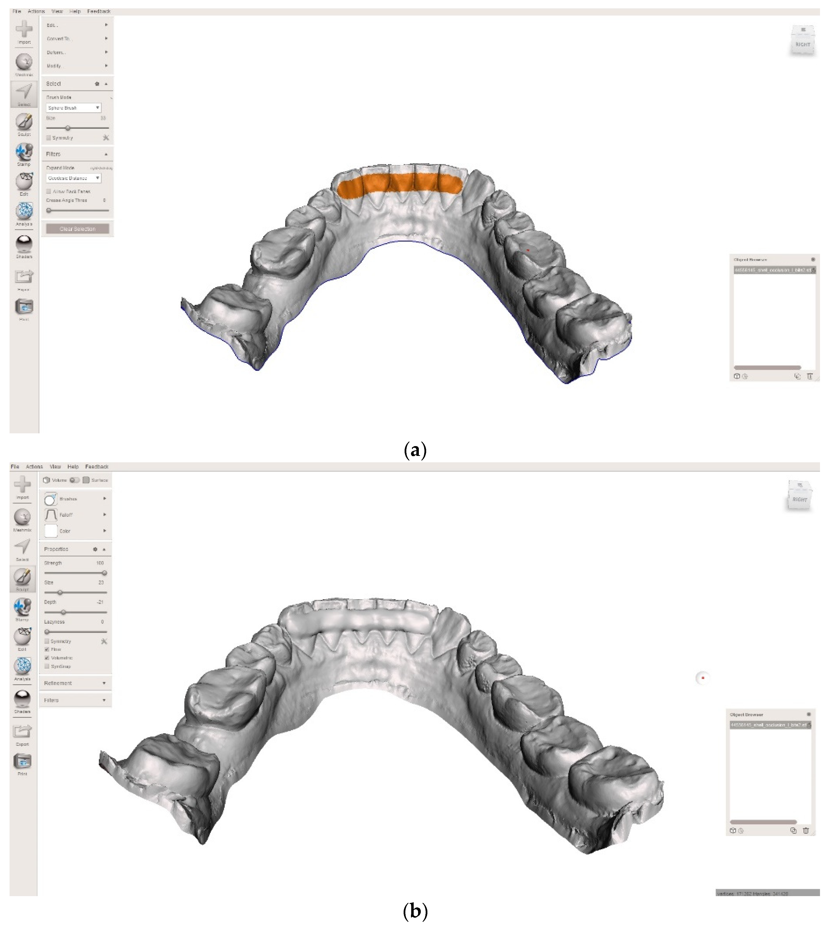
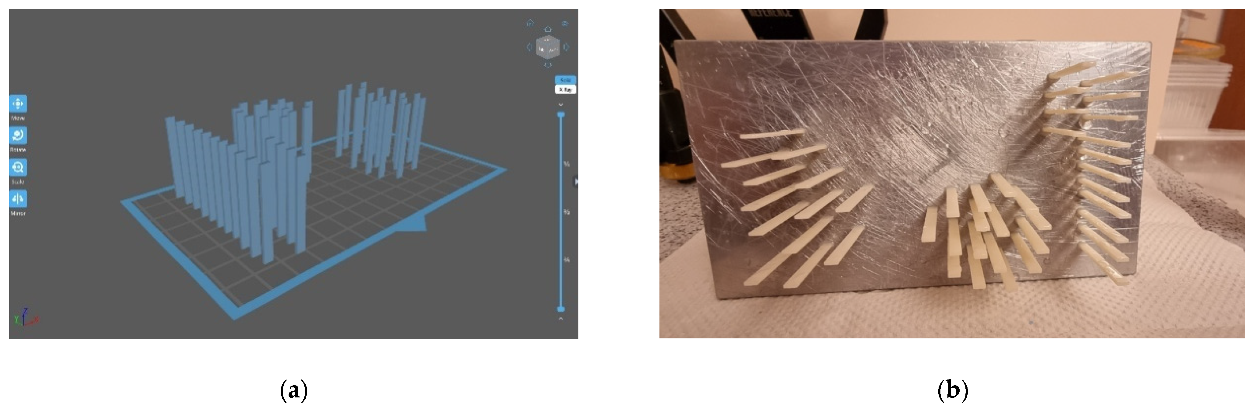
2. Materials and Methods
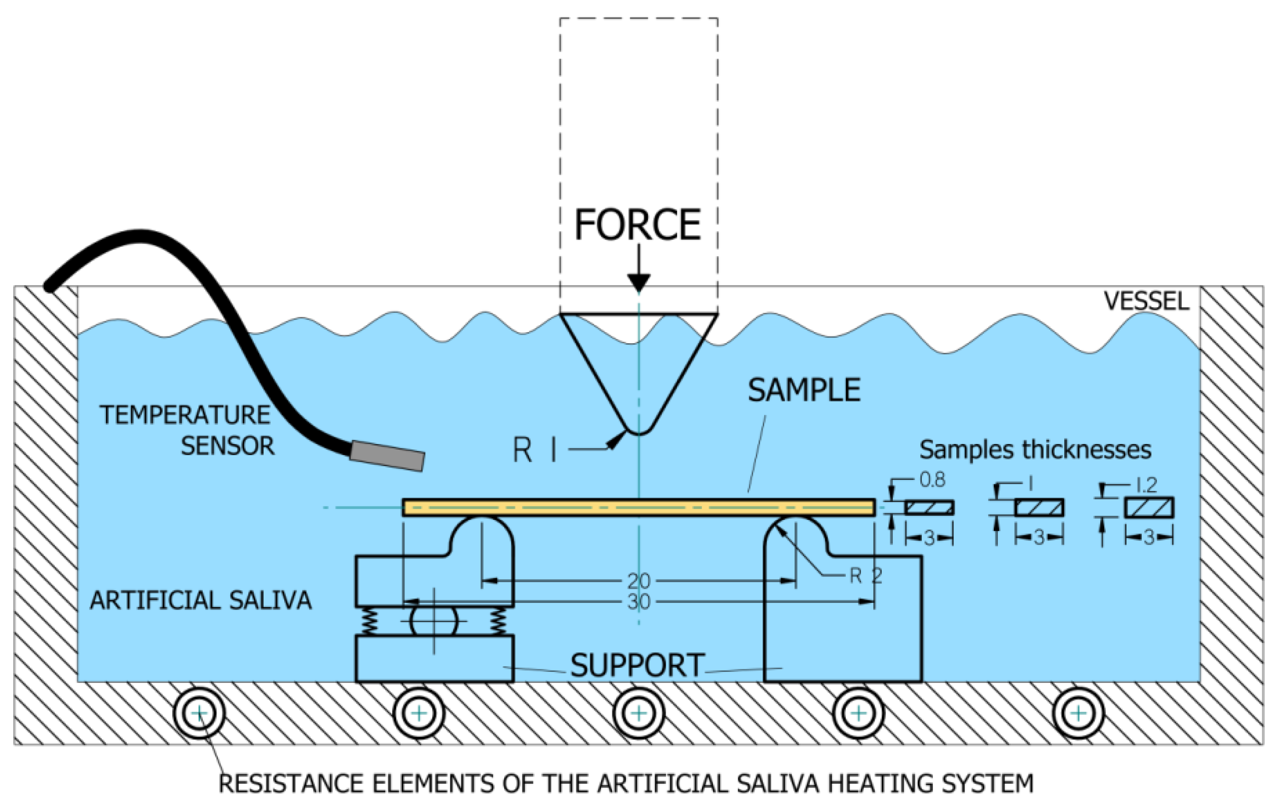
2.1. Flexural Strength and Flexural Modulus
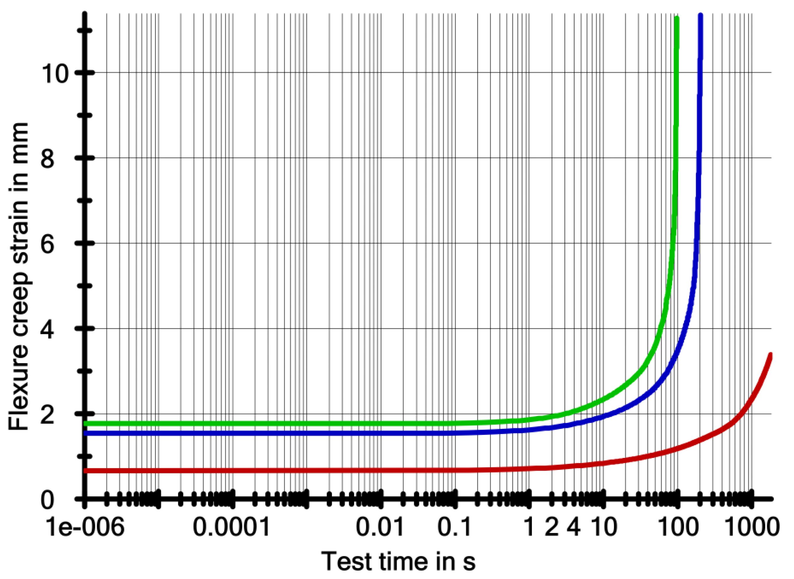
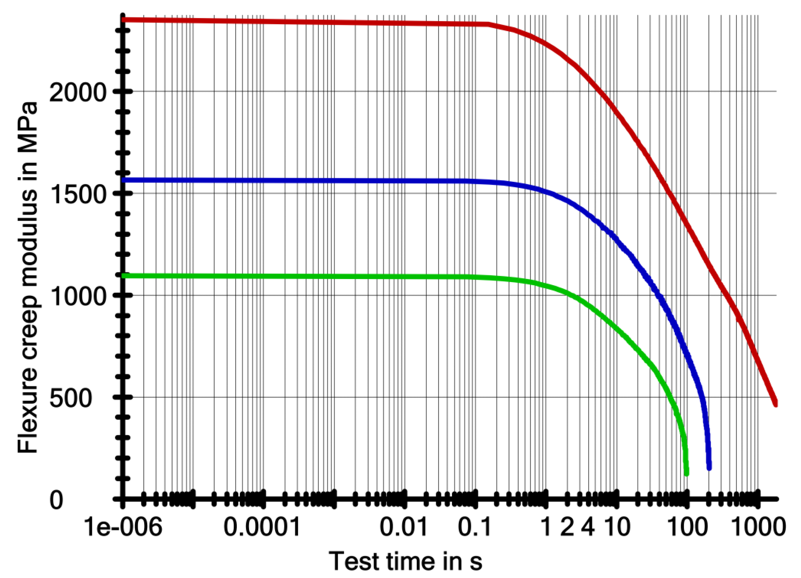
2.2. Creep Test
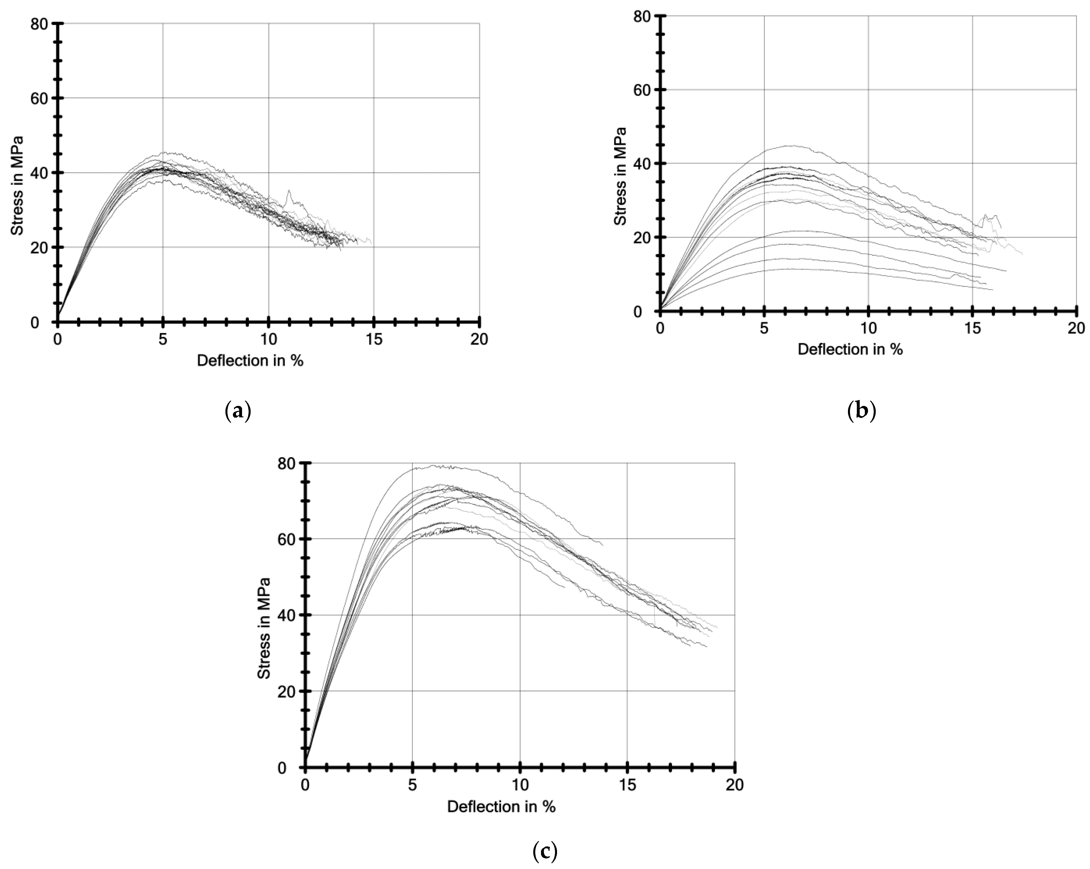
3. Results
3.1. Flexurar Strength and Elastic Module
3.2. Creep Test Results
4. Discussion
4.1. Flexurar Strength and Elastic Module Analysis
4.2. Creep Analysis
5. Conclusions
Author Contributions
Funding
Data Availability Statement
Conflicts of Interest
References
- Domagała, I.; Przystupa, K.; Firlej, M.; Pieniak, D.; Gil, L.; Borucka, A.; Naworol, I.; Biedziak, B.; Levkiv, M. Analysis of the Statis-tical Comparability of the Hardness and Wear of Polymeric Materials for Orthodontic Applications. Materials 2021, 14, 2925. [Google Scholar] [CrossRef] [PubMed]
- Domagała, I.; Przystupa, K.; Firlej, M.; Pieniak, D.; Niewczas, A.; Biedziak, B. Bending Behaviour of Polymeric Materials Used on Biomechanics Orthodontic Appliances. Materials 2020, 13, 5579. [Google Scholar] [CrossRef] [PubMed]
- Domagała, I.; Gil, L.; Firlej, M.; Pieniak, D.; Selech, J.; Romek, D.; Biedziak, B. Statistical Comparison of the Hardness and Scratch-Resistance of the PMMA Polymers Used in Orthodontic Appliances. Adv. Sci. Technol. Res. J. 2020, 14, 250–261. [Google Scholar] [CrossRef]
- Department of Orthodontics, Private Practice, Antalya, Turkey; Kartal, Y.; Kaya, B.; Department of Orthodontics, Baskent University School of Dentistry, Ankara, Turkey. Fixed Orthodontic Retainers: A Review. Turk. J. Orthod. 2019, 32, 110–114. [Google Scholar] [CrossRef] [PubMed]
- Little, R.M.; Riedel, R.A.; Artun, J. An Evaluation of Changes in Mandibular Anterior Alignment from 10 to 20 Years Postretention. Am. J. Orthod. Dentofac. Orthop. 1988, 93, 423–428. [Google Scholar] [CrossRef]
- Da Costa, R.S.M.; Vedovello, S.A.S.; Furletti-Góes, V.F.; Custodio, W.; Venezian, G.C. Orthodontist and Periodontist’s Knowledge, Attitudes and Aspects of Clinical Practice, Regarding Fixed Lower Orthodontic Retainers. Dent. Press J. Orthod. 2021, 26, e2119276. [Google Scholar] [CrossRef] [PubMed]
- Jedliński, M.; Grocholewicz, K.; Mazur, M.; Janiszewska-Olszowska, J. What Causes Failure of Fixed Orthodontic Retention?—Systematic Review and Meta-Analysis of Clinical Studies. Head Face Med. 2021, 17, 32. [Google Scholar] [CrossRef]
- Firlej, M.; Firlej, E.; Micker, A.; Cieślińska, K.; Olszewska, A.; Szponar-Żurowska, A.; Biedziak, B. Wpływ Ultradźwięków Pul-sacyjnych o Niskim Natężeniu Na Przebieg Leczenia Ortodontycznego. Nowa Stomatol. 2020, 25, 3–9. [Google Scholar] [CrossRef]
- Alrawas, M.B.; Kashoura, Y.; Tosun, Ö.; Öz, U. Comparing the Effects of CAD/CAM Nickel-titanium Lingual Retainers on Teeth Stability and Periodontal Health with Conventional Fixed and Removable Retainers: A Randomized Clinical Trial. Orthod. Craniofac. Res. 2021, 24, 241–250. [Google Scholar] [CrossRef]
- Zachrisson, P. A New Type of Fixed Retainer. Orthod. Pract. 2018, 153, 496–504. [Google Scholar]
- Beretta, M.; Mangano, A.; Gianolio, A.; Negrini, S.; Canova, F.F.; Cirulli, N. A Fully Digital Workflow for PEEK Fixed Retainers. J. Clin. Orthod. JCO 2021, 55, 249–253. [Google Scholar] [PubMed]
- Aboulazm, K.; von See, C.; Othman, A. Fixed Lingual Orthodontic Retainer with Bilateral Missing Lateral Incisors Produced in PEEK Material Using CAD/CAM Technology. J. Clin. Exp. Dent. 2021, 13, e549–e551. [Google Scholar] [CrossRef] [PubMed]
- Li, Y.; Lou, Y. Tensile and Bending Strength Improvements in PEEK Parts Using Fused Deposition Modelling 3D Printing Considering Multi-Factor Coupling. Polymers 2020, 12, 2497. [Google Scholar] [CrossRef] [PubMed]
- Firlej, M.; Pieniak, D.; Niewczas, A.M.; Walczak, A.; Domagała, I.; Borucka, A.; Przystupa, K.; Igielska-Kalwat, J.; Jarosz, W.; Biedziak, B. Effect of Artificial Aging on Mechanical and Tribological Properties of CAD/CAM Composite Materials Used in Dentistry. Materials 2021, 14, 4678. [Google Scholar] [CrossRef] [PubMed]
- Klocke, A.; Kahl-Nieke, B.; Adam, G.; Kemper, J. Magnetic Forces on Orthodontic Wires in High Field Magnetic Resonance Imaging (MRI) at 3 Tesla. J. Orofac. Orthop. Fortschr. Kieferorthopädie 2006, 67, 424–429. [Google Scholar] [CrossRef] [PubMed]
- Strassler, H.E.; Serio, C.L. Esthetic Considerations When Splinting with Fiber-Reinforced Composites. Dent. Clin. N. Am. 2007, 51, 507–524. [Google Scholar] [CrossRef]
- Sfondrini, M.F.; Gandini, P.; Tessera, P.; Vallittu, P.K.; Lassila, L.; Scribante, A. Bending Properties of Fiber-Reinforced Composites Retainers Bonded with Spot-Composite Coverage. BioMed Res. Int. 2017, 2017, 8469090. [Google Scholar] [CrossRef] [Green Version]
- Milheiro, A.; de Jager, N.; Feilzer, A.J.; Kleverlaan, C.J. In Vitro Debonding of Orthodontic Retainers Analyzed with Finite Element Analysis. Eur. J. Orthod. 2015, 37, 491–496. [Google Scholar] [CrossRef] [Green Version]
- Barenghi, L.; Barenghi, A.; Cadeo, C.; Di Blasio, A. Innovation by Computer-Aided Design/Computer-Aided Manufacturing Technology: A Look at Infection Prevention in Dental Settings. BioMed Res. Int. 2019, 2019, 6092018. [Google Scholar] [CrossRef]
- Jiang, H.; Fu, J.; Li, M.; Wang, S.; Zhuang, B.; Sun, H.; Ge, C.; Feng, B.; Jin, Y. 3D-Printed Wearable Personalized Orthodontic Retainers for Sustained Release of Clonidine Hydrochloride. AAPS PharmSciTech 2019, 20, 260. [Google Scholar] [CrossRef]
- Trebinski, R.; Wojskowa Akademia Techniczna im Jaroslawa Dabrowskiego. Aspekty Komputerowego Wspomagania Projek-Towania, Wytwarzania i Eksploatacji. Cz. 1 Cz. 1; Wojskowa Akademia Techniczna: Warszawa, Poland, 2021. [Google Scholar]
- Karbhari, V.M.; Strassler, H. Effect of Fiber Architecture on Flexural Characteristics and Fracture of Fiber-Reinforced Dental Composites. Dent. Mater. 2007, 23, 960–968. [Google Scholar] [CrossRef] [PubMed]
- ISO 10271:2020; Dentistry—Corrosion Test Methods for Metallic Materials. ISO/TC 106/SC 2 Prosthodontic Materials 2020. ISO Copyright Office: Geneva, Switzerland, 2020.
- ISO 10477:2018; Dentistry—Polymer-Based Crown and Veneering Materials. ISO/TC 106/SC 2 Prosthodontic Materials 2018. ISO Copyright Office: Geneva, Switzerland, 2018.
- Krolikowski, W.; Wydawnictwo Naukowe PWN. Polimerowe Kompozyty Konstrukcyjne; Wydawnictwo Naukowe PWN: Warszawa, Poland, 2020. [Google Scholar]
- Wolny, S.; Siemieniec, A. Wytrzymalosc Material? w. Cz. 2, Cz. 2; Uczelniane Wydawnictwa Naukowo-Dydaktyczne: Kraków, Poland, 2004. [Google Scholar]
- ISO 899-2:2003; Plastics—Determination of Creep Behaviour—Part 2: Flexural Creep by Three-Point Loading. ISO/TC 61/SC 2 Mechanical Behavior. European Committee for Standardization: Brussels, Belgium, 2003.
- ISO 899-2:1993; Plastics-Determination of Creep Characteristics-Part 2: Creep When Bending under A Three-Point Load. European Committee for Standardization: Brussels, Belgium, 1993.
- dos Santos, G.B.; Alto, R.V.M.; Filho, H.R.S.; da Silva, E.M.; Fellows, C.E. Light Transmission on Dental Resin Composites. Dent. Mater. 2008, 24, 571–576. [Google Scholar] [CrossRef] [PubMed]
- Alsandi, Q.; Ikeda, M.; Arisaka, Y.; Nikaido, T.; Tsuchida, Y.; Sadr, A.; Yui, N.; Tagami, J. Evaluation of Mechanical and Physical Properties of Light and Heat Polymerized UDMA for DLP 3D Printer. Sensors 2021, 21, 3331. [Google Scholar] [CrossRef] [PubMed]
- Kučera, J.; Marek, I.; Littlewood, S.J. The Effect of Different Bonded Retainer Wires on Tooth Mobility Immediately after Orthodontic Treatment. Eur. J. Orthod. 2021, 44, 178–186. [Google Scholar] [CrossRef] [PubMed]
- Perea-Lowery, L.; Gibreel, M.; Vallittu, P.K.; Lassila, L.V. 3D-Printed vs. Heat-Polymerizing and Autopolymerizing Denture Base Acrylic Resins. Materials 2021, 14, 5781. [Google Scholar] [CrossRef]
- Niewczas, J.; Zamościńska, J.; Krzyżak, A.; Pieniak, D.; Walczak, A.; Bartnik, G. Influence of Fibre Reinforcement on Selected Mechanical Properties of Dental Composites. Acta Bioeng. Biomech. 2017, 19, 022017. [Google Scholar] [CrossRef]
- Kuna-Ciskał, H.; Skrzypek, J.J. CDM Based Modelling of Damage and Fracture Mechanisms in Concrete under Tension and Compression. Eng. Fract. Mech. 2004, 71, 681–698. [Google Scholar] [CrossRef]
- Perkins, W.G. Polymer Toughness and Impact Resistance. Polym. Eng. Sci. 1999, 39, 2445–2460. [Google Scholar] [CrossRef]
- Pieniak, D. Initiation and Tolerance of Macro-Damage of First Ply (FBF) in a Process of Damaging of Hybrid Multi-Ply Structures Due to Reinforcement Archtecture. Adv. Mater. Sci. 2018, 18, 77–91. [Google Scholar] [CrossRef] [Green Version]
- Vaidyanathan, T. Extended Creep Behavior of Dental Composites Using Time–Temperature Superposition Principle. Dent. Mater. 2003, 19, 46–53. [Google Scholar] [CrossRef]
- Sund-Levander, M.; Forsberg, C.; Wahren, L.K. Normal Oral, Rectal, Tympanic and Axillary Body Temperature in Adult Men and Women: A Systematic Literature Review. Scand. J. Caring Sci. 2002, 16, 122–128. [Google Scholar] [CrossRef] [PubMed]
- Daniel, R.M.; Danson, M.J.; Eisenthal, R. The Temperature Optima of Enzymes: A New Perspective on an Old Phenomenon. Trends Biochem. Sci. 2001, 26, 223–225. [Google Scholar] [CrossRef]
- Chlopek, J. Effects of Stress and Biological Environment on Polymeric Implants Durability. Polimery 2005, 50, 182–189. [Google Scholar] [CrossRef] [Green Version]
- Suwanprateeb, J.; Tanner, K.E.; Turner, S.; Bonfield, W. Influence of Ringer’s solution on creep resistance of hydroxyapatite reinforced polyethylene composites. J. Mater. Sci. Mater. Med. 1997, 8, 469–472. [Google Scholar] [CrossRef]
- Wang, M.; Wang, C. Bulk Properties of Biomaterials and Testing Techniques. In Encyclopedia of Biomedical Engineering; Elsevier: Amsterdam, The Netherlands, 2019; pp. 53–64. [Google Scholar] [CrossRef]


| Material | NextDent C&B MFH |
|---|---|
| Color | N1 |
| Rinsing in Isopropyl alcohol (min) | 4.5 |
| Post-curing (min) | 30 |
| Material | NextDent C&B MFH |
|---|---|
| Layer Height | 0.050 mm |
| Bottom Layer Count | 5 |
| Exposure Time | 4.6 s |
| Transition Layers | 6 |
| Transition Type | Linear |
| Bottom Lift Distance | 6 mm |
| Lifting Distance | 6 mm |
| Lift Speed | 60 mm/min |
| Retract Speed | 150 mm/min |
| Parameter | Ef | σ0.2 | σfY | εfY | σfM | εfM | σfB | εfB | WfM | WfB |
|---|---|---|---|---|---|---|---|---|---|---|
| Unit | MPa | MPa | MPa | % | MPa | % | MPa | % | Nmm | Nmm |
| Samples thickness of 0.8 mm | ||||||||||
| 1200 | 34.7 | 41.7 | 5.1 | 41.7 | 5.1 | 20.8 | 13.5 | 8.45 | 24.51 | |
| s | 85.1 | 1.77 | 1.91 | 0.3 | 1.91 | 0.3 | 0.956 | 0.6 | 1.07 | 2.34 |
| ν | 7.07 | 5.11 | 4.59 | 6.74 | 4.59 | 6.74 | 4.59 | 4.52 | 12.72 | 9.56 |
| Samples thickness of 1 mm | ||||||||||
| 786 | 22.7 | 29.9 | 6.2 | 29.9 | 6.2 | 14.9 | 15.9 | 9.11 | 25.55 | |
| s | 313 | 7.11 | 10.4 | 0.4 | 10.4 | 0.4 | 5.18 | 0.7 | 3.11 | 8.40 |
| ν | 39.83 | 31.32 | 34.66 | 6.16 | 34.66 | 6.16 | 34.67 | 4.66 | 34.15 | 32.88 |
| Samples thickness of 1.2 mm | ||||||||||
| 1950 | 46.0 | 70.8 | 6.9 | 70.8 | 6.9 | 40.4 | 16.7 | 29.07 | 75.98 | |
| s | 176 | 4.54 | 4.75 | 0.7 | 4.75 | 0.7 | 10.7 | 3.0 | 4.40 | 12.33 |
| ν | 9.03 | 9.86 | 6.71 | 9.85 | 6.71 | 9.85 | 26.59 | 17.64 | 15.12 | 16.23 |
| No. | Stage Number | Load Time | Et | εt | σt | σfract | εfract | τfract |
|---|---|---|---|---|---|---|---|---|
| min | N/mm2 | % | MPa | MPa | mm | s | ||
| Sample thickness of 0.8 mm | ||||||||
| 1 | 1 | 1 | 881.61 | 3.36 | 30 | 20.7 | 11.4 | 203.2 |
| 2 | 3 | 402.33 | 7.31 | 30 | - | - | - | |
| 3 | 6 | - | - | - | - | - | - | |
| 4 | 12 | - | - | - | - | - | - | |
| 5 | 30 | - | - | - | - | - | - | |
| Sample thickness of 1 mm | ||||||||
| 2 | 1 | 1 | 481.93 | 6.20 | 30 | 20.9 | 11.3 | 97.2 |
| 2 | 3 | - | - | - | - | - | - | |
| 3 | 6 | - | - | - | - | - | - | |
| 4 | 12 | - | - | - | - | - | - | |
| 5 | 30 | - | - | - | - | - | - | |
| Sample thickness of 1.2 mm | ||||||||
| 3 | 1 | 1 | 1483.77 | 2.02 | 30 | - | - | - |
| 2 | 3 | 1180.28 | 2.54 | 30 | - | - | - | |
| 3 | 6 | 1001.71 | 2.99 | 30 | - | - | - | |
| 4 | 12 | 796.44 | 3.76 | 30 | - | - | - | |
| 5 | 30 | 466.35 | 6.38 | 30 | - | - | - | |
Publisher’s Note: MDPI stays neutral with regard to jurisdictional claims in published maps and institutional affiliations. |
© 2022 by the authors. Licensee MDPI, Basel, Switzerland. This article is an open access article distributed under the terms and conditions of the Creative Commons Attribution (CC BY) license (https://creativecommons.org/licenses/by/4.0/).
Share and Cite
Firlej, M.; Zaborowicz, K.; Zaborowicz, M.; Firlej, E.; Domagała, I.; Pieniak, D.; Igielska-Kalwat, J.; Dmowski, A.; Biedziak, B. Mechanical Properties of 3D Printed Orthodontic Retainers. Int. J. Environ. Res. Public Health 2022, 19, 5775. https://doi.org/10.3390/ijerph19095775
Firlej M, Zaborowicz K, Zaborowicz M, Firlej E, Domagała I, Pieniak D, Igielska-Kalwat J, Dmowski A, Biedziak B. Mechanical Properties of 3D Printed Orthodontic Retainers. International Journal of Environmental Research and Public Health. 2022; 19(9):5775. https://doi.org/10.3390/ijerph19095775
Chicago/Turabian StyleFirlej, Marcel, Katarzyna Zaborowicz, Maciej Zaborowicz, Ewa Firlej, Ivo Domagała, Daniel Pieniak, Joanna Igielska-Kalwat, Artur Dmowski, and Barbara Biedziak. 2022. "Mechanical Properties of 3D Printed Orthodontic Retainers" International Journal of Environmental Research and Public Health 19, no. 9: 5775. https://doi.org/10.3390/ijerph19095775