
Residual Stresses Control in Additive Manufacturing


1
International Centre for Numerical Methods in Engineering, Universidad Politécnica de Cataluña, 08034 Barcelona, Spain
2
State Key Laboratory of Solidification Processing, Northwestern Polytechnical University, Xi’an 710072, China
*
Author to whom correspondence should be addressed.
J. Manuf. Mater. Process. 2021, 5(4), 138; https://doi.org/10.3390/jmmp5040138
Submission received: 25 November 2021
/
Revised: 9 December 2021
/
Accepted: 14 December 2021
/
Published: 16 December 2021
(This article belongs to the Topic Additive Manufacturing)
Abstract
:Residual stresses are one of the primary causes for the failure of parts or systems in metal additive manufacturing (AM), since they easily induce crack propagation and structural distortion. Although the formation of residual stresses has been extensively studied, the core factors steering their development in AM have not been completely uncovered. To date, several strategies based on reducing the thermal gradients have been developed to mitigate the manifestation of residual stresses in AM; however, how to choose the optimal processing plan is still unclear for AM designers. In this regard, the concept of the yield temperature, related to the thermal deformation and the mechanical constraint, plays a crucial role for controlling the residual stresses, but it has not been duly investigated, and the corresponding approach to control stresses is also yet lacking. To undertake such study, a three-bar model is firstly used to illustrate the formation mechanism of the residual stress and its key causes. Next, an experimentally calibrated thermomechanical finite element model is used to analyze the sensitivity of the residual stresses to the scan pattern, preheating, energy density, and the part geometry and size, as well as the substrate constraints. Based on the numerical results obtained from this analysis, recommendations on how to minimize the residual stresses during the AM process are provided.
1. Introduction
Metal additive manufacturing (AM) is an advanced processing technology of increasing industrial significance due to its unique advantages and its feasibility to fabricate complex structures with high-performance [1,2]. During the AM process, the material experiences repeated spatially variable heating and cooling cycles. Locally, non-uniform thermal expansion and contraction happen at the vicinity of the melt pool, where high temperature gradients arise during the printing process and lead to thermal deformations and residual stresses, these being detrimental for the geometrical accuracy and the final mechanical properties of the AM components [3,4].
Due to the large number of variables involved in the AM process, the combination of experiments and numerical simulations is quite useful to study the thermo-mechanical behavior, duly accounting for the limitations of experimental measurements and the mandatory validation of the computational models [5,6,7,8,9]. In this line, Lu et al. [6,7] studied the residual stresses and distortion of Ti-6Al-4V single-wall and rectangular parts using a finite element (FE) model calibrated by establishing an in situ system with integrated infrared imaging sensor, thermocouples, digital image correlation, and displacement sensor, which can measure the detailed temperature and distortion of Ti-6Al-4V parts manufactured by directed energy deposition (DED). Cao et al. [8] developed an efficient FE model by combining the dynamic mesh method and the equivalent boundary condition to accelerate the thermo-mechanical simulations of laser powder bed fusion (LPBF).
Several studies have been performed on the optimization of the process to reduce the residual stresses and distortion. It is found that optimizing the deposition sequence or the process parameters [5,10,11,12] and preheating the substrate before the AM [3,9] can minimize the residual stresses and warpage. Nevertheless, such strategies based on managing the thermal gradients in metal AM are limited, due to the use of a high-energy beam as the heat source. For example, preheating the substrate or build chamber may increase the risk of microstructure coarsening; the optimization of path and process parameters is relatively complex, and it needs to give consideration to the microstructural evolution. Additionally, the use of assistant tools, such as in the rolling technique [13] and laser shock peening [14], during AM or the post-processing stress relieving (by heat or mechanical treatments) [15,16] favor stress reduction, but increase both manufacturing time and cost. Although these strategies have been proposed, their combined necessary comparison and evaluation for optimizing the AM process when printing complex components must be further investigated.
To date, the formation of residual stresses is mainly attributed in the existing literature to the “temperature gradient mechanism” [17,18,19]; little attention has been paid to the “yield temperature”, another crucial factor related to the mechanical constraint. As known, free temperature deformation causes no stress, even if the thermal gradient is important. Based on this concept, the optimization of the substrate restraints should be addressed to reduce the stress development during the metal AM processes, as a new control route, parallel to the conventional thermal gradient management.
Thereby, the objective of this work is to uncover the key mechanisms that drive the residual stresses in AM and to make a comprehensive assessment on their control strategies. To this end, a simple three-bar model used in welding is firstly employed to illustrate the two core factors, namely, the thermal gradient and the yield temperature, as responsible for the emergence of the residual stresses in AM. Based on this new appreciation, the sensitivity of the stress development to the scan pattern, preheating, the part geometry and size, and the mechanical constraint of the substrate is studied using a 3D coupled thermo-mechanical FE model for AM. Finally, some recommendations for fabricating high-quality AM parts are given.
2. Experimental Setup
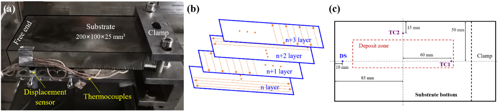
A 40-layer Ti-6Al-4V block (125 × 35 × 20 mm3) was deposited by DED on an annealed Ti-6Al-4V substrate (200 × 100 × 25 mm3) clamped as a cantilever, as shown in Figure 1a. The laser-based DED machine employed includes a semiconductor laser diode with a maximum output power of 6 kW, a DPSF-2 high-accuracy powder feeder, a five-axis numerical control robot and a hermetic processing chamber filled with argon. Before DED, the Ti-6Al-4V powders with a diameter of between 53–325 μm were dried in a vacuum oven at 130 °C for 2 h.
The process parameters are: a laser power of 2 kW, a scan speed of 15.0 mm/s, a laser beam diameter of 5.0 mm, and an up-lift height of 0.5 mm; an alternating longitudinal-transverse printing pattern is used, as shown in Figure 1b. During the DED process, two Omega GG-K-30 thermocouples and one WXXY PM11-R1-20L displacement sensor are used to measure the temperature and the vertical displacement of the bottom of the substrate without preheating, as shown in Figure 1c.
3. Numerical Simulation
3.1. Thermomechanical Analysis for AM
In this work, an in-house coupled thermo-mechanical FE software, COMET [20,21], is utilized to perform the mechanical analyses. For each time step, the thermal analysis is performed firstly, and then the computed temperature field is used to solve the stress problem.
The energy balance equation for the transient thermal analysis is:
where is the enthalpy rate, is the heat source, and is the heat flux, defined by Fourier’s law:
where is the thermal conductivity, and is the temperature gradient.
The convective heat dissipation is computed by Newton’s law:
where is the heat convective coefficient, is the component temperature, and is the ambient temperature.
The heat loss by radiation, , is defined by Stefan–Boltzmann’s law:
where is the surface emissivity, and is the Stefan–Boltzmann constant.
The balance of momentum equation for the stress analysis is:
where the Cauchy stress tensor is split into its deviatoric and spherical parts, and , respectively, as
is the body force, is the displacement, is the bulk modulus, and is the thermal deformation, defined as:
where is the solid fraction, is the initial temperature, and and are the thermal expansion and shrinkage coefficients, respectively.
In this work, a J2-thermo-elasto-visco-plastic model is utilized in the solid phase, corresponding to the temperatures from to the annealing temperature, . All the material properties are supposed to be temperature dependent. The von Mises yield surface is expressed as:
where is the yield stress, and is the stress-like variable controlling the hardening, defined as:
where is the isotropic strain-hardening variable, is the saturation flow stress, and the parameters and are used to model the linear and exponential hardening laws, respectively. The deviatoric counterpart of Cauchy’s stress tensor is defined as:
where is the shear modulus, is the total (deviatoric) strain obtained from the total strain tensor , and is the visco-plastic strain. Based on the principle of maximum plastic dissipation, the evolutions of both the visco-plastic strain tensor and the isotropic strain-hardening variable are expressed as:
where stands for the normal vector to the yield surface, and is the visco-plastic multiplier, defined as:
where is the rate sensitivity and is plastic viscosity.
Note that as , the yield stress tends to null. Hence, the deviatoric Cauchy stress is reduced to:
where stands for the effective viscosity. Hereby, the materials are characterized by a purely viscous law when . A non-Newtonian behavior with is used for the mushy phase (), while a Newtonian law, , features the liquid phase (). The details of this model for AM simulation are given in previous works [22,23,24].
3.2. FE Modelling of AM
To model the printing process, a time-marching scheme, featured by a time step, , is used, allowing for the time discretization. Hence, the melting pool can move according to the deposition path from the current position at time to that at time . In this interval, the elements corresponding to the melting pool are heated and, at the same time, the feeding powders conform the metal deposition.
Thereby, the simulation software parses the same file (CLI format) following the real printing path as used to inform the 3D printer. The birth-and-death-element technique is utilized to activate the elements belonging to the new deposit layer. Thus, the simulated strategy for the building process requires an ad hoc procedure to classify the elements into: activated, active, and inactive element. At each time step, the elements corresponding to the melting pool (active) and to the deposit layers (activated) are sought by an octree-based searching algorithm. Both the active and activated elements are included in the current computational domain, but the inactive ones are neither assembled nor computed.
Figure 2 shows the different AM geometries and the corresponding FE meshes. The geometry in Figure 2a corresponds to the in situ experimental work-piece, while Figure 2b,c depict the two four-layer blocks with the different geometries: rectangular and square shapes, respectively. The mesh size is 1×1×0.5 mm3 for the deposit, while it is larger for the substrate, increasing with the distance from the printing region. The temperature-dependent mechanical and thermal properties of Ti-6Al-4V, used for both the build and the substrate, are from references [25,26].
3.3. Model Calibration
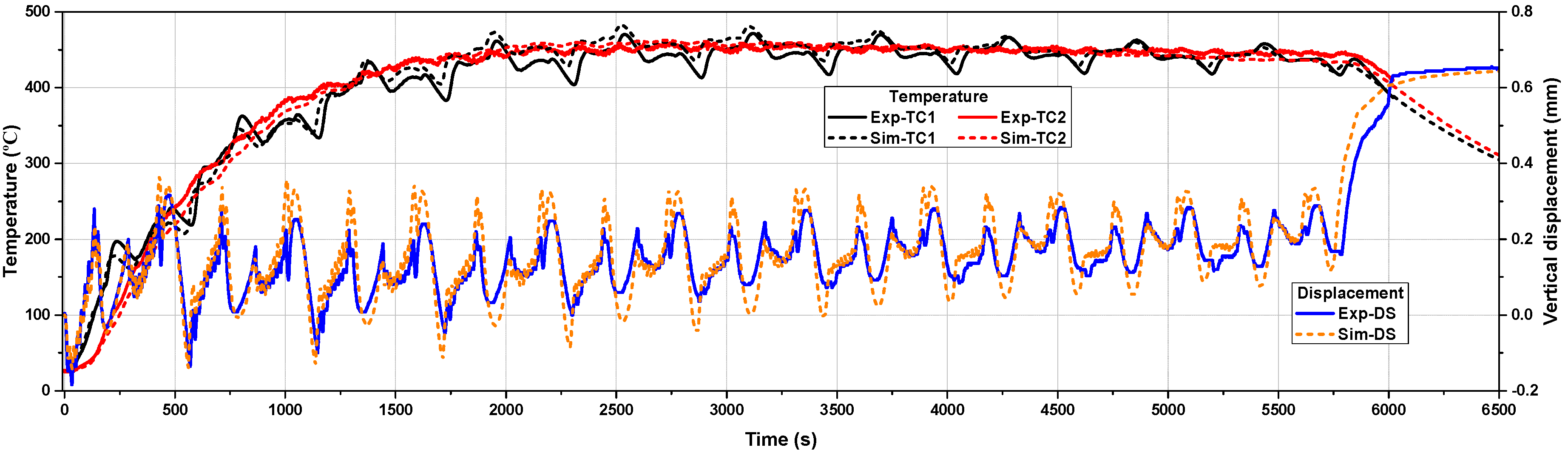
Prior to studying the sensitivity of the residual stresses to the AM variables, the thermo-mechanical model needs to be calibrated to ensure its prediction accuracy. Figure 3 compares the measured and calculated thermo-mechanical results of the 40-layer block. Note that the agreement between the simulation and the experiment is remarkable, as reported in reference [20]. The fluctuations in the plots are due to the use of the alternating longitudinal-transverse scan path (Figure 1b) in the DED process. The differences between the numerical and experimental results are attributed to the simplifications of the thermal boundary conditions in the building process. For instance, the non-uniform gas flow inside the processing chamber adopted to avoid oxidation during DED process is not modeled.
The thermal boundary conditions used for the simulation are: a laser efficiency of 0.37, a heat convection coefficient of 5 W/(m2·°C), a heat emissivity of 0.45, and an ambient temperature of 25·°C.
This successful model calibration illustrates that the FE software is a powerful pool to predict the AM process. Thereby, the software can be employed to study the effect of different AM variables in order to optimize the fabrication process.
4. Residual Stresses and Distortions
First, the generation of residual stresses and their key factors are analyzed based on a simple three-bar model. Next, the effect of the scan pattern, the preheating, the energy density, the part geometry, and the mechanical constraint of the substrate on the mechanical responses during the AM process are studied to identify the optimal strategy to mitigate residual stress and distortion.
4.1. Key Factors for the Formation of Residual Stresses in AM
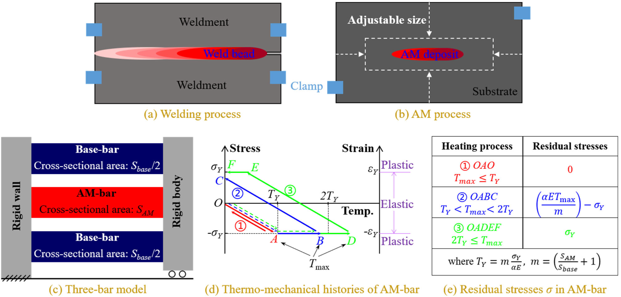
From the viewpoint of the mechanical response, the AM process is similar to welding due to the use of a high energy beam as the input heat in both cases, as shown in Figure 4a,b. In welding, a three-bar model [27] is employed to demonstrate the formation of residual stresses, as shown in Figure 4c. The three bars are one central AM-bar and two lateral base-bars of equal lengths, and their cross-sectional areas are SAM and Sbase/2, respectively. The left end of all three bars is fixed, while the right end is bound with a movable rigid link. For simplicity, the material of the three-bars is assumed to be elastic-perfectly plastic under loading, with a temperature-independent Young’s modulus E, a thermal expansion coefficient , and a yield stress . As thermal straining depends on incremental temperature, the base-bar temperature is set at 0 °C for simplicity. When heating the AM-bar, its thermomechanical response is subjected to the maximum heating temperature Tmax (points A, B, or D), as shown in Figure 4d. Figure 4e lists the residual stresses in the AM-bar for different heating processes; the detailed deduction can be found in reference [27]. Here, is the yield temperature, which is defined as the temperature that causes the material yielding in the AM-bar fixed at both ends either by heating or cooling, and expressed as:
where m represents the degree of mechanical restraint from the base-bars. Usually, m is unchanged in welding, allowing for the fixed geometry and size of the given weldments (see Figure 4a), but this is not the case for AM, because the substrate size can be chosen before printing a component (see Figure 4b).
Based on this three-bar model, two key factors are identified as responsible for the development of residual stresses in AM.
The first one is the maximum temperature difference (MTD) between the AM-bar and the base-bar during the thermal cycling. As the base-bar temperature is 0 °C, MTD is equal to the maximum heating temperature reached in the AM-bar. As known, MTD corresponds to the maximum temperature gradient (MTG) around the melt pool during the printing process. It can be seen from Figure 4d that the smaller the , the smaller the developed residual stresses.
The second factor is the yield temperature, , which is very important but not commonly considered in the past. By reducing , is increased, and this favors the reduction in the residual stresses by reducing the formation of plastic strain (see stages in Figure 4d). In addition, the slope of the line OA in elasticity, , which determines the range of the elastic behavior, is also a function of .
4.2. Effect of the Scan Pattern
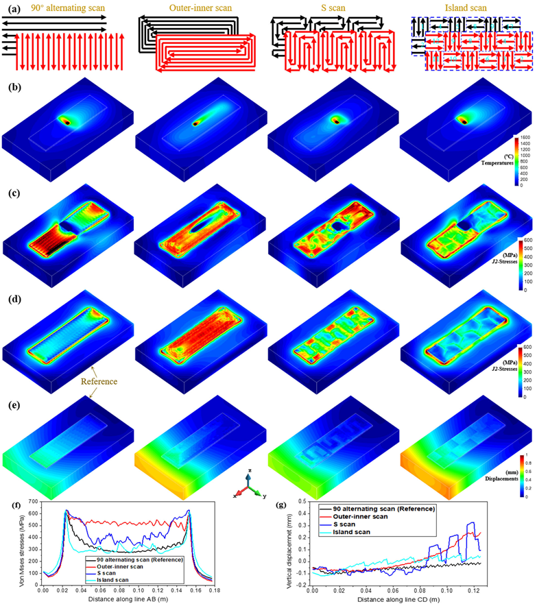
In this section, four different scan patterns are chosen to investigate their effect on the residual stress and distortion: 90° alternating scan, outer-inner scan, island scan, and S scan proposed in [28]; they are shown in Figure 5a.
Figure 5b,c show the computed temperature and the corresponding stress fields when depositing the second layer, respectively. Note that, for the 90° alternating scan, the large residual stress produced after the 1st layer is significantly alleviated during the printing of the second layer, because using the shorter scan path increases the heat concentration, favoring the MTG reduction and stress relaxation. Likewise, the island pattern with the shorter scan line yields the lowest stress level in the four cases. Contrariwise, high stresses appear in the deposit manufactured by the outer–inner scan (covering many long scan lines), which increases the nonuniformity of the temperature distribution (see Figure 5b). The S-pattern presents a slight reduction in the stresses due to its shorter scan line.
Figure 5d,f show the contour-fills of von Mises residual stresses and the stress distributions at the build–substrate interface for the different building strategies. It can be seen that the 90° alternating and island patterns yield the smallest residual stresses, whereas the outer-inner scan displays a conspicuous stress accumulation. Although the S-pattern favors stress mitigation, its effect is limited.
Figure 5e,g show the final distortion contour-fills and the vertical displacement distributions on the built top for the different scan patterns. The 90° alternating and island scans produce the smallest vertical displacement due to their shorter scan line. The outer–inner and S scans lead to a noticeable longitudinal bending of the deposit and an undulant displacement distribution, respectively, thus reducing the geometrical precision of the parts.
Although optimizing the printing path can minimize MTG and the residual stresses in the inner of the deposit by uniformizing the temperature distribution during AM process, it fails to alleviate the stress concentrations (see Figure 5d) at the built basement where the highest MTG occurs with the strongest mechanical constraint.
4.3. Influence of Preheating, Deposit Height and Energy Density
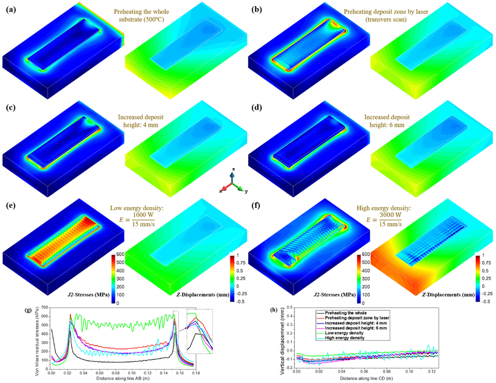
Usually, preheating the substrate before AM is a very efficient method to reduce the MTG induced by the printing process. Here, two different preheating conditions are considered: (i) a 500 °C preheating temperature for the whole substrate and (ii) using the transverse scan to preheat the deposit surface of the substrate, respectively. Figure 6a,b show the corresponding mechanical responses of the four-layer rectangular block. Note that, compared with the reference with no preheating (see Figure 5), the laser preheating fails to refrain the development of the stresses, while preheating the whole baseplate achieves a pronounced reduction in the residual stresses (see Figure 6g). Regrettably, a high preheating temperature easily causes microstructural coarsening and yields poor mechanical properties [29]. Additionally, no obvious difference is found in the part displacements for the different preheating conditions (see Figure 5g and Figure 6h).
The deposited height of the AM part also affects the residual stresses, allowing for the potential intrinsic heat treatment (IHT) effect on the stress relaxation as the printing process extends [13]. Figure 6c,d present the contour-fills of the residual stresses and deformations of the rectangular blocks with an increased built height: 4 mm (8-layer) and 6 mm (12-layer), respectively. Apparently, the inner residual stresses are gradually mitigated as the printing height increases, due to IHT and reduced MTG. However, stress concentrations still hold at the corner of the builds. The part distortions are barely changed with the built height.
As is known, the laser energy density can significantly influence the magnitude of the MTG during the AM process. Thereby, its effect on the mechanical behavior of AM components is examined next. Figure 6e,f show the predicted mechanical results for the low and high energy densities, , respectively. Observe that increasing the favors stress minimization but leads to a larger part warpage. The reason for this is that a higher tends to yield larger MTG and plastic deformation; it can also promote stress relief by ITH if the localized heat is sufficiently accumulated (see Figure 5c), especially for AM Ti-6Al-4V [30] or low-temperature transformation alloys [31], in which their solid-state phase-transformations can help stress relaxation.
4.4. Effect of the Substrate Stiffness and the Part Geometry
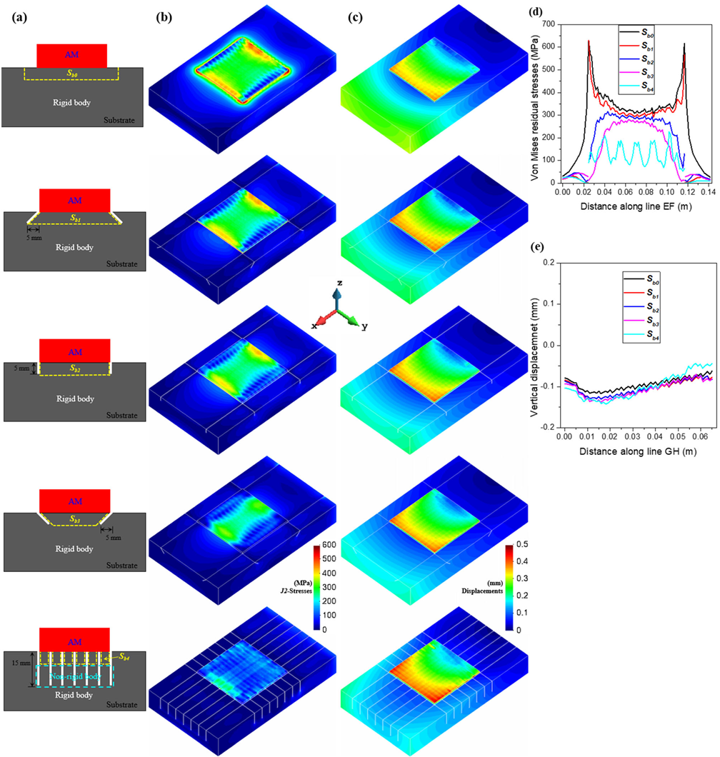
While the residual stresses in AM can be reduced using the above approaches focusing on reducing the MTG, they have no effect on preventing stress concentrations (see Figure 5d and Figure 6). To address this problem, it is possible to prevent the residual stress initiation by increasing (reducing the substrate restraint) from the purely mechanical point of view (see Figure 4). Thereby, the sensitivity of the mechanical constraints of the substrate on residual stresses is evaluated by simulating the four-layer square blocks fabricated on the same sized substrates but with different cut settings, as shown in Figure 7a.
Referring to the bar model (see Figure 4c), the upper part of the substrate near the AM deposit acts as a base-bar, while the rest of the substrate is rigid (see Figure 7a). According to Equation (16), the area of the upper of the substrate (marked by yellow lines) decreases from to , as shown in Figure 7a; thus, the corresponding yield temperature rises in sequence, favoring the mitigation of the residual stress (plastic deformation) during AM.
Figure 7b,d display the contour-fills of the residual stresses and the stress distributions at the deposit–substrate interface for different substrate settings. Note that the residual stresses are remarkably minimized by lowering the mechanical restraint of the substrate. For the sample, both the inner stresses and the stress concentration at the corner of the deposit are much lowered, almost without compromising the distortions, as shown in Figure 7c,e.
5. Conclusions
In this work, a 3D coupled thermomechanical FE model for AM is firstly calibrated by in situ temperature and displacement measurements using a 40-layer block. This done, a three-bar model is used as a conceptual aid to understand the generation of residual stresses in AM and to extract the two key causes: (i) the maximum temperature gradient, MTG, and (ii) the yield temperature, , related to the mechanical restraint during thermal deformation. Next, utilizing the calibrated thermomechanical model, several strategies on reducing the residual stresses, such as the optimization of path and process parameter and preheating of the substrate and design of the substrate, are systematically evaluated. It is found that the approaches previously developed based on the MTG control can minimize the inner residual stress of the builds but are useless for avoiding the residual stress concentrations at the deposited basement, this often being the source of cracking and failure of the parts. Contrarily, the proposed strategy of increasing , by lowering the mechanical restraint of the substrate to AM deposit, efficiently prevents the development of the residual stress and stress concentration during the printing process.
Concurrently controlling the MTG and and utilizing the IHT annealing (if possible) can be used for mitigating the residual stresses during the DED processes. However, the LPBF process is typically characterized by higher MTG and weaker IHT; thus, increasing to control the stress accumulation would be highly beneficial.
Author Contributions
Conceptualization, X.L. (Xufei Lu); Funding acquisition, X.L. (Xin Lin); Software, M.C. (Michele Chiumenti); Supervision, M.C. (Miguel Cervera), M.C. (Michele Chiumenti) and X.L. (Xin Lin); Writing—original draft, X.L. (Xufei Lu); Writing—review & editing, M.C. (Miguel Cervera). All authors have read and agreed to the published version of the manuscript.
Funding
This work was funded by the National Key R&D Program of China (No. 2016YFB1100100), the European KYKLOS 4.0 project (No. 872570) and the China Scholarship Council (No. 201906290011).
Data Availability Statement
Data are contained within the article.
Conflicts of Interest
The authors declare no conflict of interest.
References
- Baiges, J.; Chiumenti, M.; Moreira, C.A.; Cervera, M.; Codina, R. An adaptive Finite Element strategy for the numerical simulation of additive manufacturing processes. Addit. Manuf. 2021, 37, 101650. [Google Scholar] [CrossRef]
- Chiumenti, M.; Lin, X.; Cervera, M.; Lei, W.; Zheng, Y.; Huang, W. Numerical Simulation and Experimental Calibration of Additive Manufacturing by Blown Powder Technology. Part I: Thermal Analysis. Rapid Prototyp. J. 2017, 23, 448–463. [Google Scholar] [CrossRef] [Green Version]
- Lu, X.; Lin, X.; Chiumenti, M.; Cervera, M.; Li, J.; Ma, L.; Wei, L.; Hu, Y.; Huang, W. Finite Element Analysis and Experimental Validation of the Thermomechanical Behavior in Laser Solid Forming of Ti-6Al-4V. Addit. Manuf. 2018, 21, 30–40. [Google Scholar] [CrossRef]
- Lu, X.; Chiumenti, M.; Cervera, M.; Tan, H.; Lin, X.; Wang, S. Warpage Analysis and Control of Thin-Walled Structures Manufactured by Laser Powder Bed Fusion. Metals 2021, 11, 686. [Google Scholar] [CrossRef]
- Zhang, W.; Tong, M.; Harrison, N.M. Scanning strategies effect on temperature, residual stress and deformation by multi-laser beam powder bed fusion manufacturing. Addit. Manuf. 2020, 36, 101507. [Google Scholar] [CrossRef]
- Lu, X.; Lin, X.; Chiumenti, M.; Cervera, M.; Hu, Y.; Ji, X.; Ma, L.; Huang, W. In situ measurements and thermo-mechanical simulation of Ti–6Al–4V laser solid forming processes. Int. J. Mech. Sci. 2019, 153–154, 119–130. [Google Scholar] [CrossRef]
- Lu, X.; Lin, X.; Chiumenti, M.M.; Cervera, M.; Hu, Y.; Ji, X.; Ma, L.; Huang, W. Residual Stress and Distortion of Rectangular and S-Shaped Ti-6Al-4V Parts by Directed Energy Deposition: Modelling and Experimental Calibration. Addit. Manuf. 2019, 26, 166–179. [Google Scholar] [CrossRef]
- Cao, Y.; Lin, X.; Kang, N.; Ma, L.; Wei, L.; Zheng, M.; Yu, J.; Peng, D.; Huang, W. A novel high-efficient finite element analysis method of powder bed fusion additive manufacturing. Addit. Manuf. 2021, 46, 102187. [Google Scholar] [CrossRef]
- Cao, J.; Gharghouri, M.A.; Nash, P. Finite-element analysis and experimental validation of thermal residual stress and distortion in electron beam additive manufactured Ti-6Al-4V build plates. J. Mater. Process. Technol. 2016, 237, 409–419. [Google Scholar] [CrossRef]
- Lu, X.; Cervera, M.; Chiumenti, M.; Li, J.; Ji, X.; Zhang, G.; Lin, X. Modeling of the Effect of the Building Strategy on the Thermomechanical Response of Ti-6Al-4V Rectangular Parts Manufactured by Laser Directed Energy Deposition. Metals 2020, 10, 1643. [Google Scholar] [CrossRef]
- Levkulich, N.; Semiatin, S.; Gockel, J.; Middendorf, J.; DeWald, A.; Klingbeil, N. The effect of process parameters on residual stress evolution and distortion in the laser powder bed fusion of Ti-6Al-4V. Addit. Manuf. 2019, 28, 475–484. [Google Scholar] [CrossRef]
- Mugwagwa, L.; Dimitrov, D.; Matope, S.; Yadroitsev, I. Influence of process parameters on residual stress related distortions in selective laser melting. Procedia Manuf. 2018, 21, 92–99. [Google Scholar] [CrossRef]
- Hönnige, J.; Colegrove, P.; Ahmad, B.; Fitzpatrick, M.; Ganguly, S.; Lee, T.L.; Williams, S. Residual stress and texture control in Ti-6Al-4V wire + arc additively manufactured intersections by stress relief and rolling. Mater. Des. 2018, 150, 193–205. [Google Scholar] [CrossRef] [Green Version]
- Kalentics, N.; Boillat, E.; Peyre, P.; Ciric-Kostic, S.; Bogojevic, N.; Logé, R.E. Tailoring residual stress profile of Selective Laser Melted parts by Laser Shock Peening. Addit. Manuf. 2017, 16, 90–97. [Google Scholar] [CrossRef] [Green Version]
- Sames, W.; List, F.; Pannala, S.; Dehoff, R.; Babu, S. The metallurgy and processing science of metal additive manufacturing. Int. Mater. Rev. 2016, 61, 315–360. [Google Scholar] [CrossRef]
- Guo, W.; Sun, R.; Song, B.; Zhu, Y.; Li, F.; Che, Z.; Li, B.; Guo, C.; Liu, L.; Peng, P. Laser shock peening of laser additive manufactured Ti6Al4V titanium alloy. Surf. Coatings Technol. 2018, 349, 503–510. [Google Scholar] [CrossRef]
- Mugwagwa, L.; Yadroitsava, I.; Makoana, N.W.; Yadroitsev, I. Residual stress in laser powder bed fusion. In Fundamentals of Laser Powder Bed Fusion of Metals; Elsevier BV: Amsterdam, The Netherlands, 2021; pp. 245–276. [Google Scholar]
- Fang, Z.-C.; Wu, Z.-L.; Huang, C.-G.; Wu, C.-W. Review on residual stress in selective laser melting additive manufacturing of alloy parts. Opt. Laser Technol. 2020, 129, 106283. [Google Scholar] [CrossRef]
- Bartlett, J.L.; Li, X. An overview of residual stresses in metal powder bed fusion. Addit. Manuf. 2019, 27, 131–149. [Google Scholar] [CrossRef]
- Lu, X.; Chiumenti, M.; Cervera, M.; Zhang, G.; Lin, X. Mitigation of residual stresses and microstructure homogenization in directed energy deposition processes. Eng. Comput. 2021, in press. [Google Scholar]
- Chiumenti, M.; Cervera, M.; Salmi, A.; de Saracibar, C.A.; Dialami, N.; Matsui, K. Finite element modeling of multi-pass welding and shaped metal deposition processes. Comput. Methods Appl. Mech. Eng. 2010, 199, 2343–2359. [Google Scholar] [CrossRef]
- Chiumenti, M.; Neiva, E.; Salsi, E.; Cervera, M.; Badia, S.; Moya, J.; Chen, Z.; Lee, C.; Davies, C. Numerical Modelling and Experimental Validation in Selective Laser Melting. Addit. Manuf. 2017, 18, 171–185. [Google Scholar] [CrossRef] [Green Version]
- Chiumenti, M.; Cervera, M.; Moreira, C.; Barbat, G. Stress, strain and dissipation accurate 3-field formulation for inelastic isochoric deformation. Finite Elements Anal. Des. 2021, 192, 103534. [Google Scholar] [CrossRef]
- Chiumenti, M.; Cervera, M.; Dialami, N.; Wu, B.; Jinwei, L.; de Saracibar, C.A. Numerical modeling of the electron beam welding and its experimental validation. Finite Elem. Anal. Des. 2016, 121, 118–133. [Google Scholar] [CrossRef] [Green Version]
- Lu, X.; Zhang, G.; Li, J.; Cervera, M.; Chiumenti, M.; Chen, J.; Lin, X.; Huang, W. Simulation-assisted investigation on the formation of layer bands and the microstructural evolution in directed energy deposition of Ti6Al4V blocks. Virtual Phys. Prototyp. 2021, 16, 387–403. [Google Scholar] [CrossRef]
- Lu, X.; Chiumenti, M.; Cervera, M.; Li, J.; Lin, X.; Ma, L.; Zhang, G.; Liang, E. Substrate design to minimize residual stresses in Directed Energy Deposition AM processes. Mater. Des. 2021, 202, 109525. [Google Scholar] [CrossRef]
- Ueda, Y.; Murakawa, H.; Ma, N. Welding Deformation and Residual Stress Prevention; Elsevier BV: Amsterdam, The Netherlands, 2012; pp. 5–25. [Google Scholar]
- Sun, L.; Ren, X.; He, J.; Zhang, Z. Numerical investigation of a novel pattern for reducing residual stress in metal additive manufacturing. J. Mater. Sci. Technol. 2021, 67, 11–22. [Google Scholar] [CrossRef]
- Xue, A.; Lin, X.; Wang, L.; Lu, X.; Ding, H.; Huang, W. Heat-affected coarsening of β grain in titanium alloy during laser directed energy deposition. Scr. Mater. 2021, 205, 114180. [Google Scholar] [CrossRef]
- Denlinger, E.R.; Michaleris, P. Effect of stress relaxation on distortion in additive manufacturing process modeling. Addit. Manuf. 2016, 12, 51–59. [Google Scholar] [CrossRef] [Green Version]
- Chen, W.; Xu, L.; Han, Y.; Zhao, L.; Jing, H. Control of residual stress in metal additive manufacturing by low-temperature solid-state phase transformation: An experimental and numerical study. Addit. Manuf. 2021, 42, 102016. [Google Scholar] [CrossRef]
Figure 1.
DED process: (a) in situ experimental set-up; (b) scanning path used; (c) locations of two thermocouples (TC1-TC2) and one displacement sensor (DS) at the bottom surface of the substrate.
Figure 1.
DED process: (a) in situ experimental set-up; (b) scanning path used; (c) locations of two thermocouples (TC1-TC2) and one displacement sensor (DS) at the bottom surface of the substrate.

Figure 2.
FE mesh models: (a) 40-layer rectangular block; (b) 4-layer rectangular block; (c) 4-layer square block. The lines AB and EF at the build-substrate interface are used to analyze the residual stresses while the lines CD and GH at the deposit top are used to analyze the displacement of DED parts.

Figure 3.
Comparison between simulated and measured thermo-mechanical results of the block.

Figure 4.
The formation of residual stresses in welding and AM processes.

Figure 5.
Rectangular block: (a) scan patterns; (b) temperature and (c) von Mises stress during the deposition of the 2nd layer; (d) residual stresses; (e) final distortions (displacements norm); (f) residual von Mises stresses along the AB line at the baseplate top; (g) final vertical displacements along the CD line at the deposit top.

Figure 6.
Contour-fills of residual von Mises stresses and the vertical displacements for different AM processes: preheating (a) the whole substrate to 500 °C and (b) the deposit region on the substrate surface by laser (transverse scan); increasing the deposit height to (c) 4 mm and (d) 6 mm, respectively; using the (e) lower and (f) higher energy to fabricate AM block, respectively; (g) residual von Mises stresses along the AB line at the substrate top; (h) vertical displacements along the CD line at the deposit top.

Figure 7.
Square block: (a) different substrate designs; (b) von Mises stress field; (c) final distortions (displacements norm); (d) residual von Mises stresses along the EF line at the baseplate top; (e) vertical displacements along the GH line at the deposit top.
Figure 7.
Square block: (a) different substrate designs; (b) von Mises stress field; (c) final distortions (displacements norm); (d) residual von Mises stresses along the EF line at the baseplate top; (e) vertical displacements along the GH line at the deposit top.

Publisher’s Note: MDPI stays neutral with regard to jurisdictional claims in published maps and institutional affiliations. |
© 2021 by the authors. Licensee MDPI, Basel, Switzerland. This article is an open access article distributed under the terms and conditions of the Creative Commons Attribution (CC BY) license (https://creativecommons.org/licenses/by/4.0/).
Share and Cite
MDPI and ACS Style
Lu, X.; Cervera, M.; Chiumenti, M.; Lin, X. Residual Stresses Control in Additive Manufacturing. J. Manuf. Mater. Process. 2021, 5, 138. https://doi.org/10.3390/jmmp5040138
AMA Style
Lu X, Cervera M, Chiumenti M, Lin X. Residual Stresses Control in Additive Manufacturing. Journal of Manufacturing and Materials Processing. 2021; 5(4):138. https://doi.org/10.3390/jmmp5040138
Chicago/Turabian StyleLu, Xufei, Miguel Cervera, Michele Chiumenti, and Xin Lin. 2021. "Residual Stresses Control in Additive Manufacturing" Journal of Manufacturing and Materials Processing 5, no. 4: 138. https://doi.org/10.3390/jmmp5040138