
Injection Lap Riveting of Aluminum Busbars—A Thermo-Electro-Mechanical Investigation

 , and
, and 
Abstract
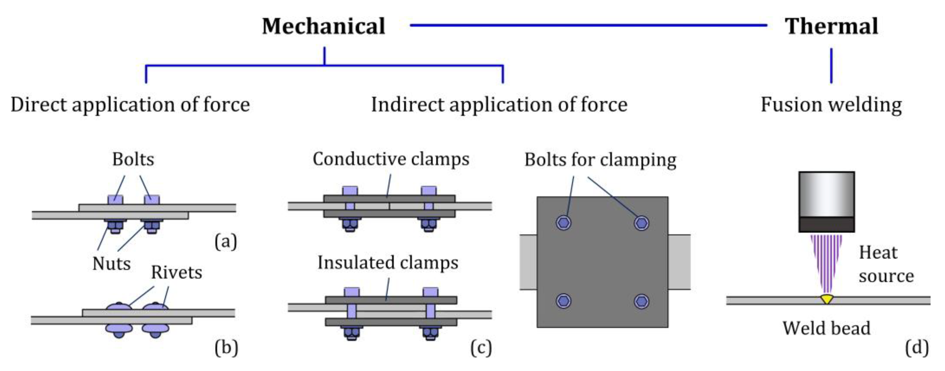
:1. Introduction
2. Materials and Methods
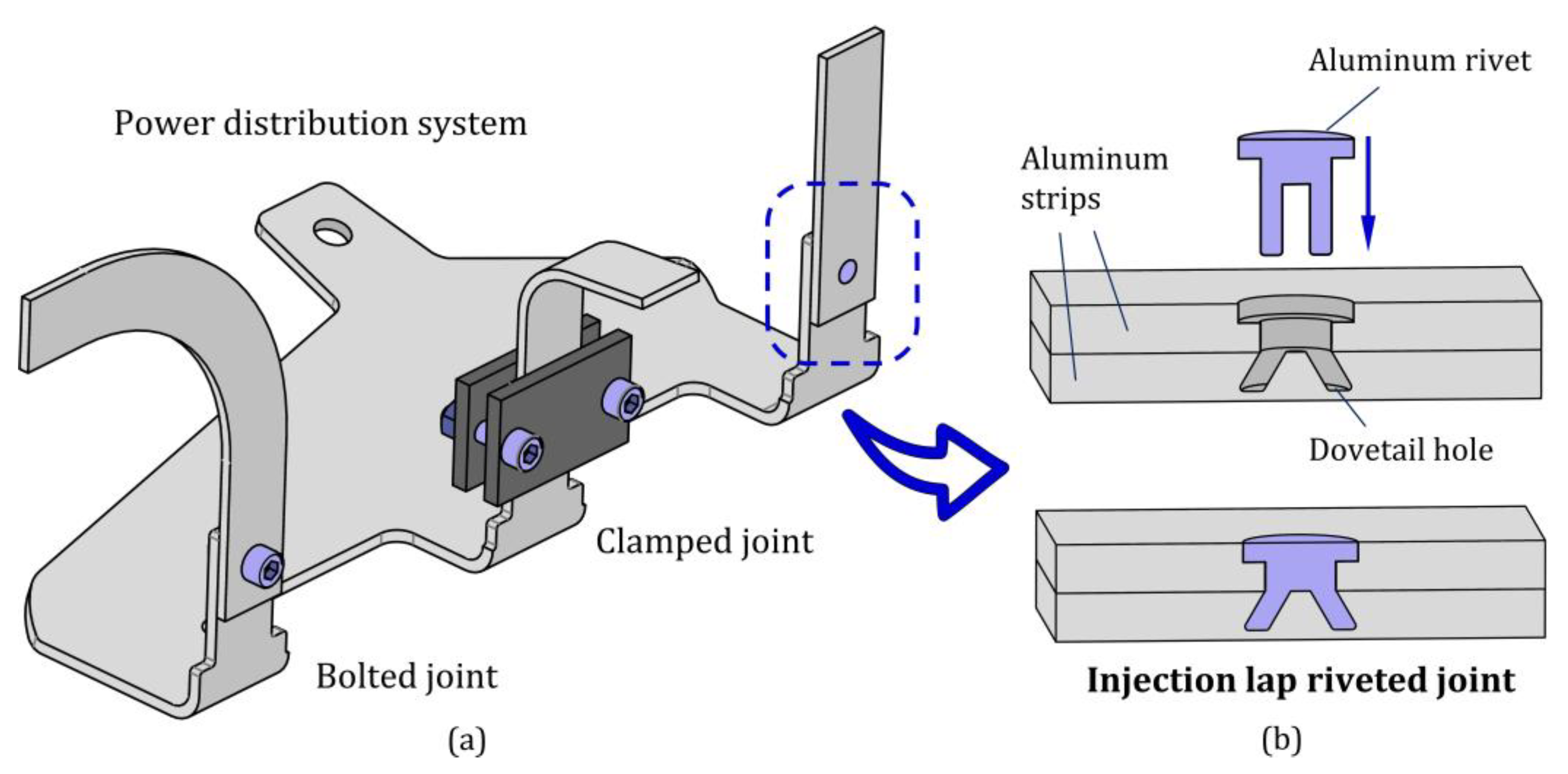
2.1. Fabrication of the Joints
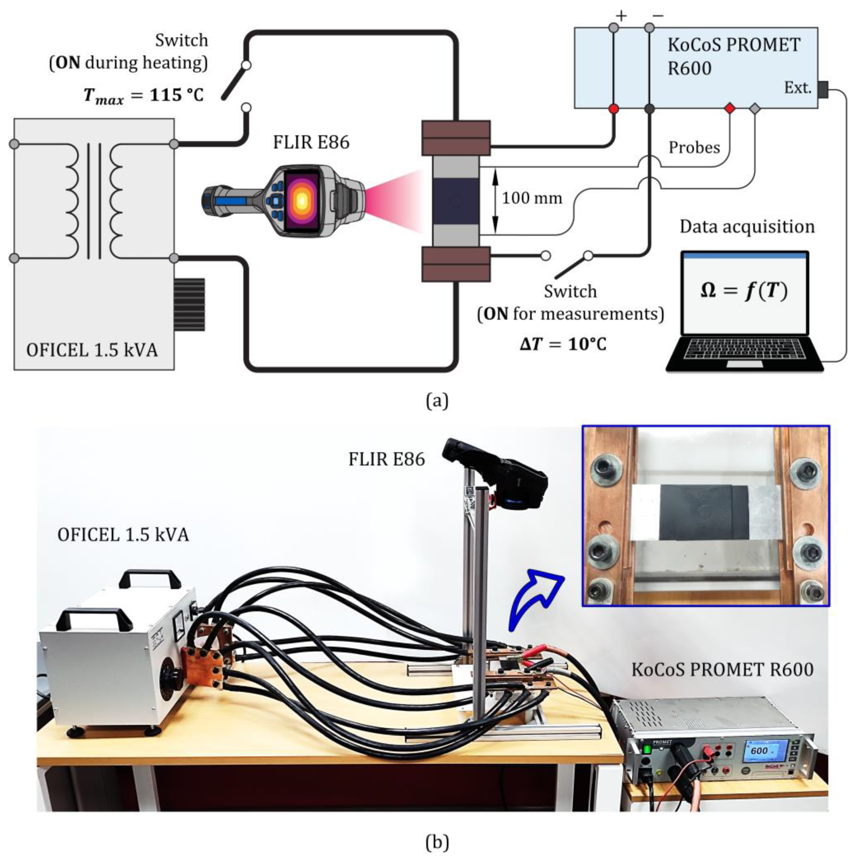
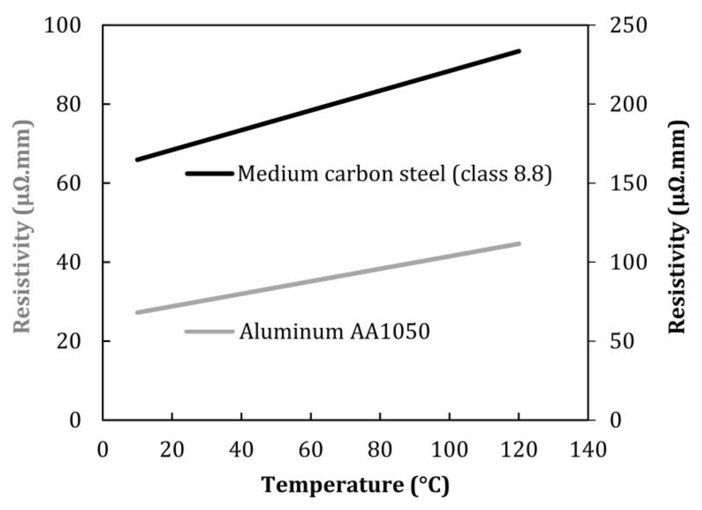
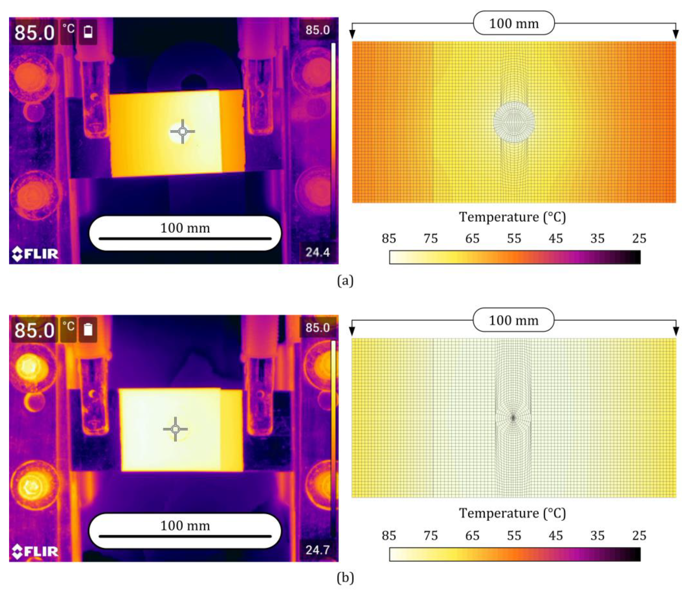
2.2. Thermo-Electrical Characterization of the Materials and Joints
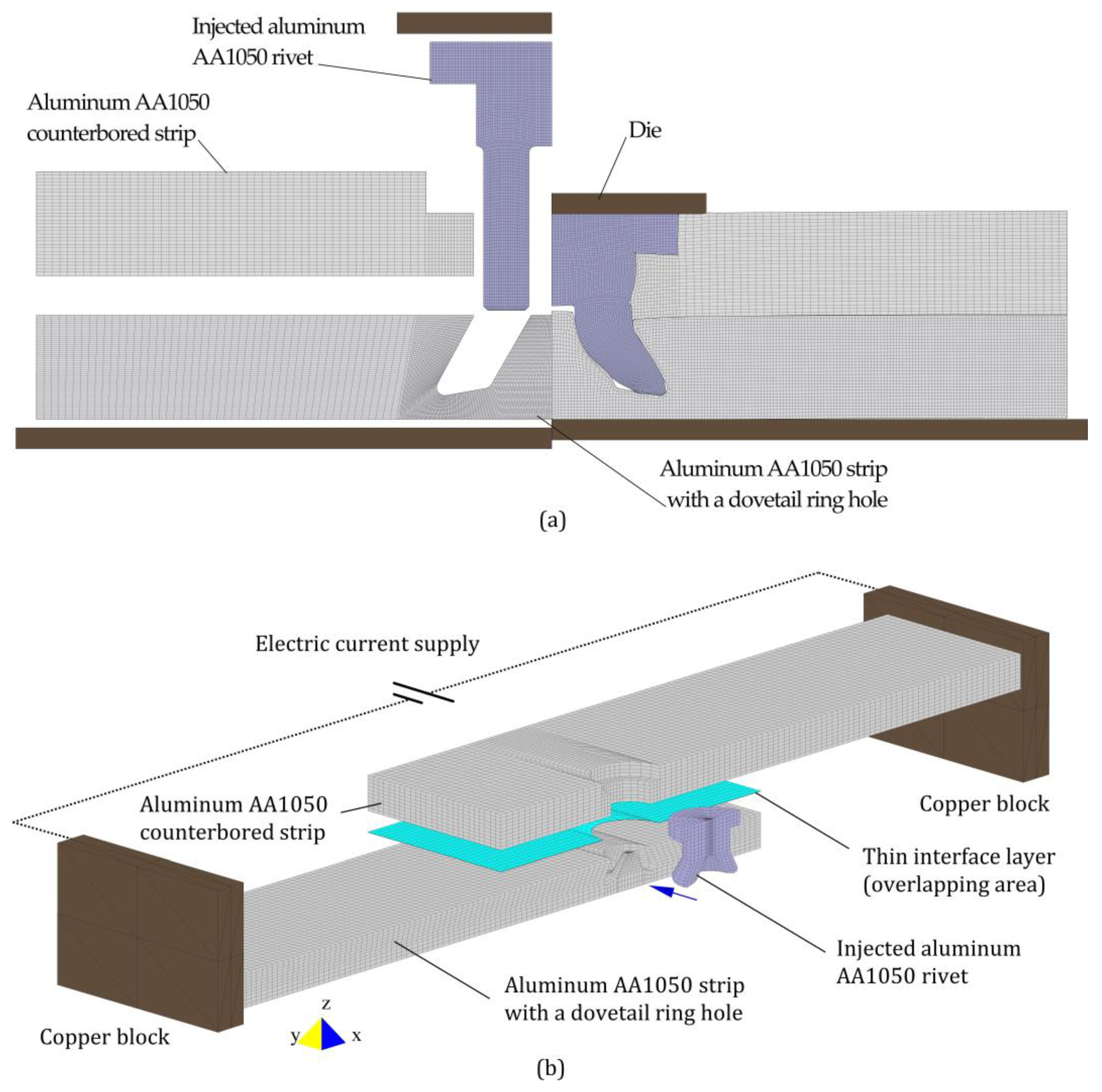
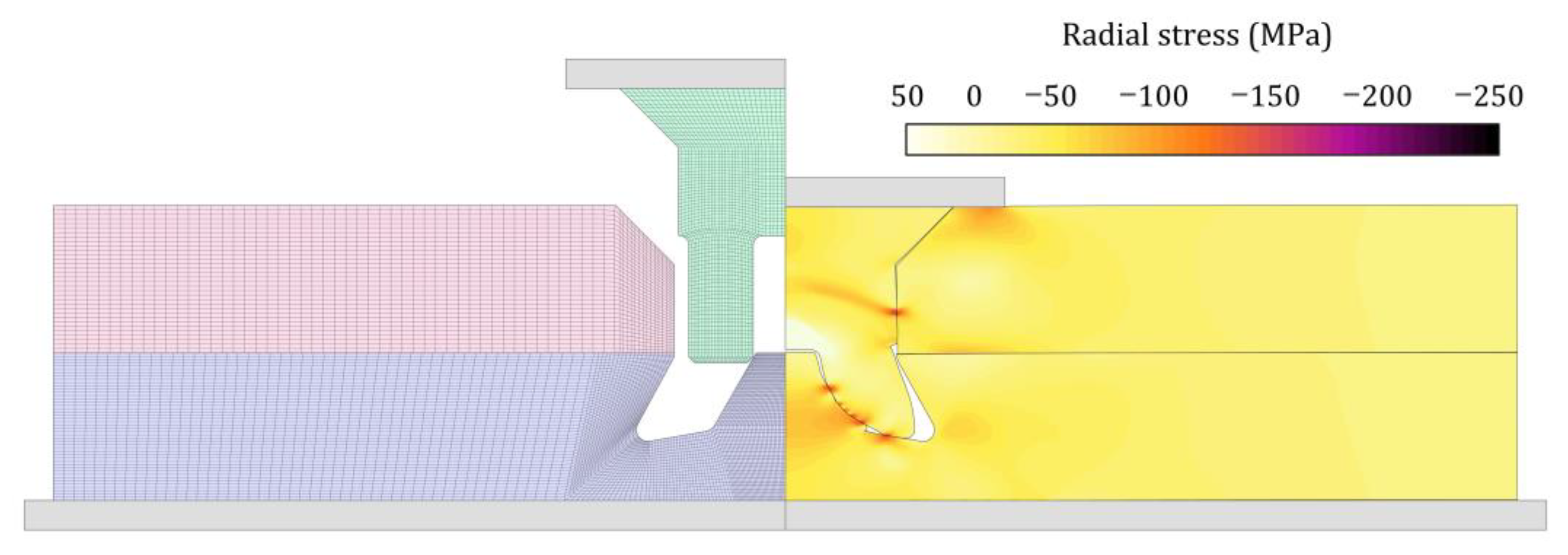
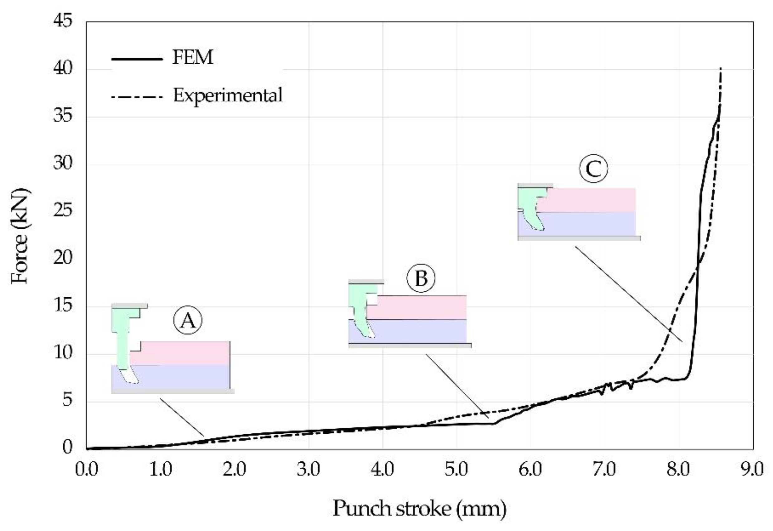
2.3. Numerical Modelling
3. Results and Discussion
3.1. Injection Lap Riveting
3.2. Thermo-Electro Characterization of the Joints
3.3. Future Research Directions
4. Conclusions
- Injection lap riveted joints require much less space for assembly than alternative solutions based on conventional bolting or riveting due to the absence of material protrusions above and below the joint surfaces.
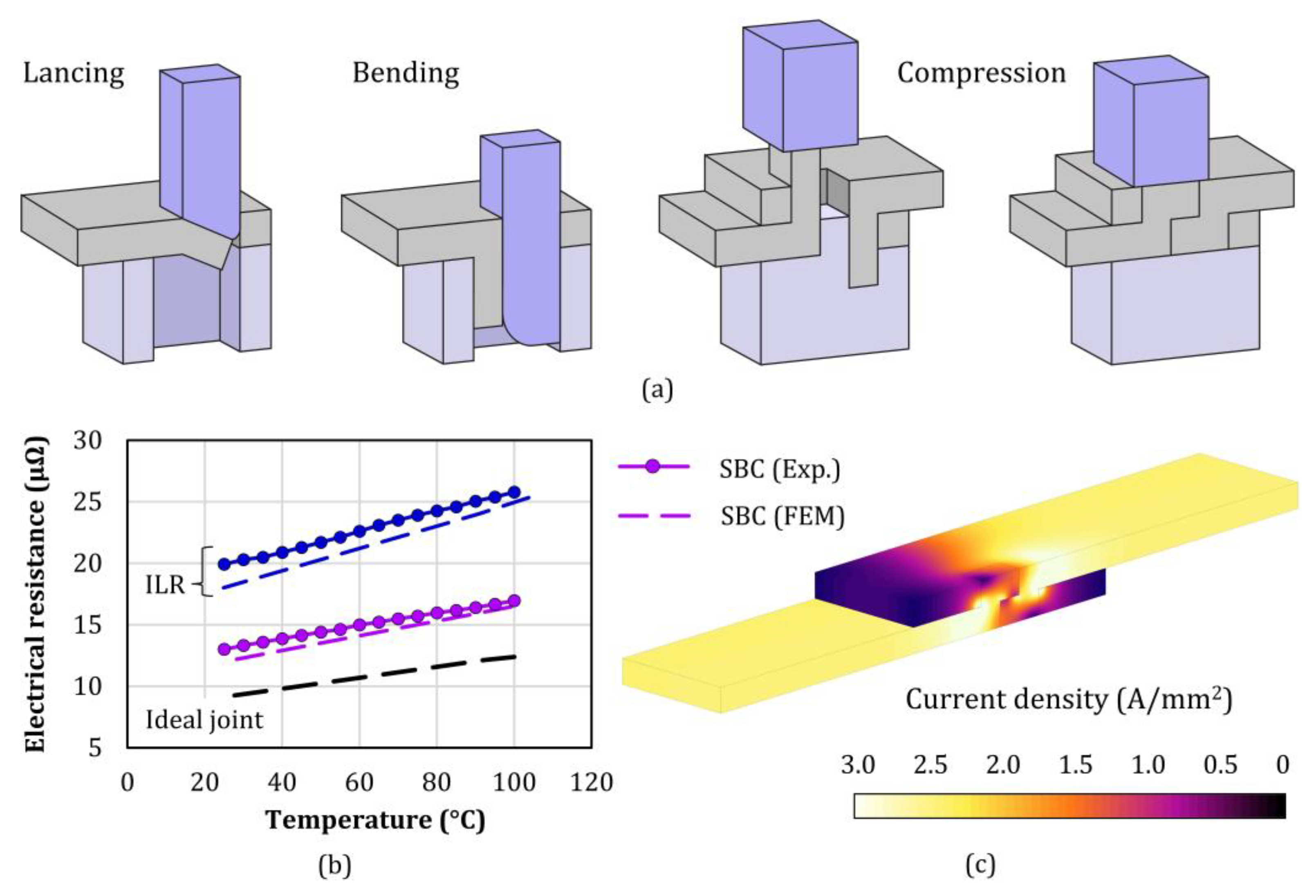
- Semi-tubular rivet heads must have counterbored geometries and appropriate shank lengths to ensure complete filling with good mechanical interlocking and appropriate contact pressures on the overlapping areas between the two busbar strip conductors.
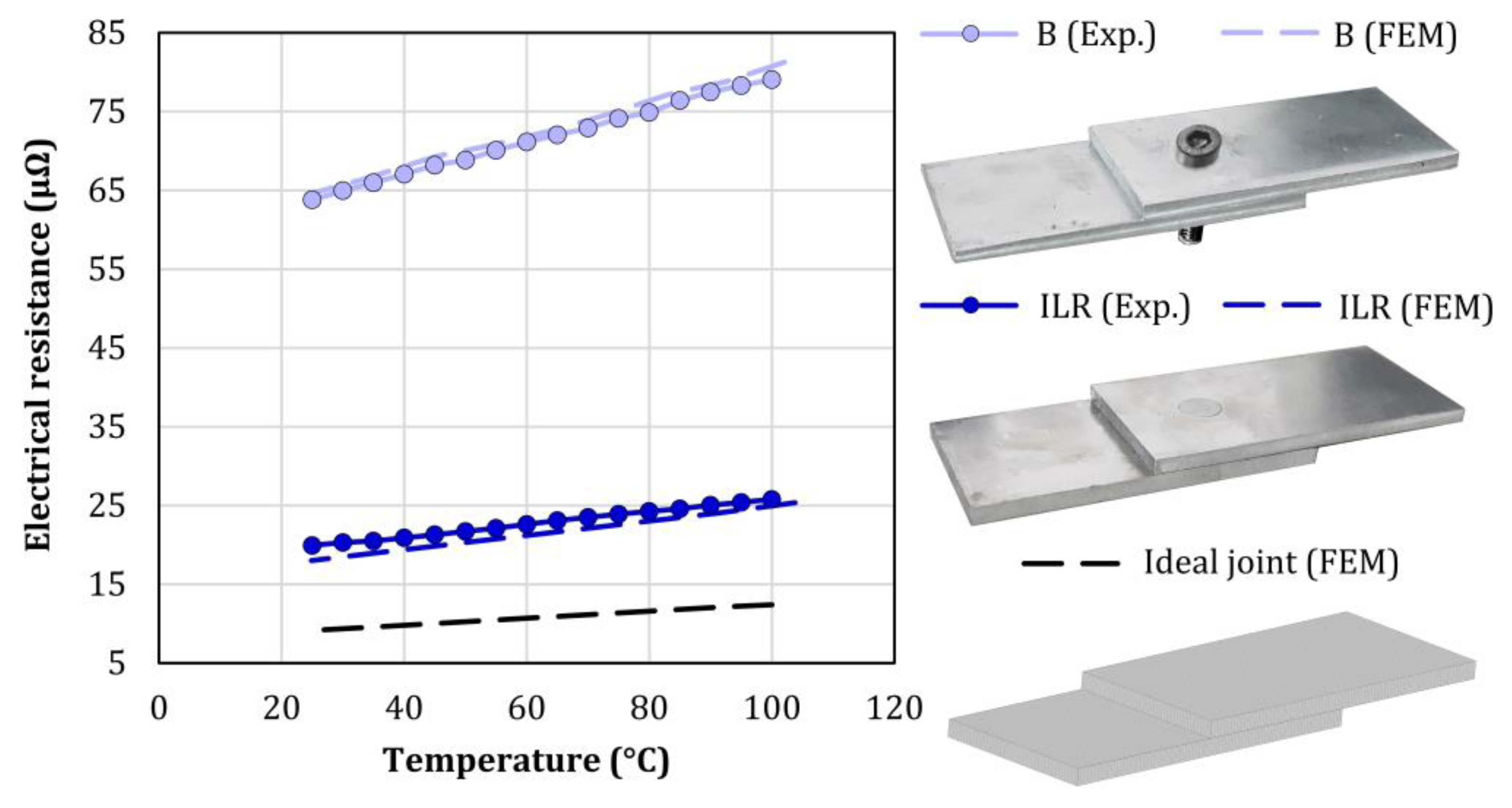
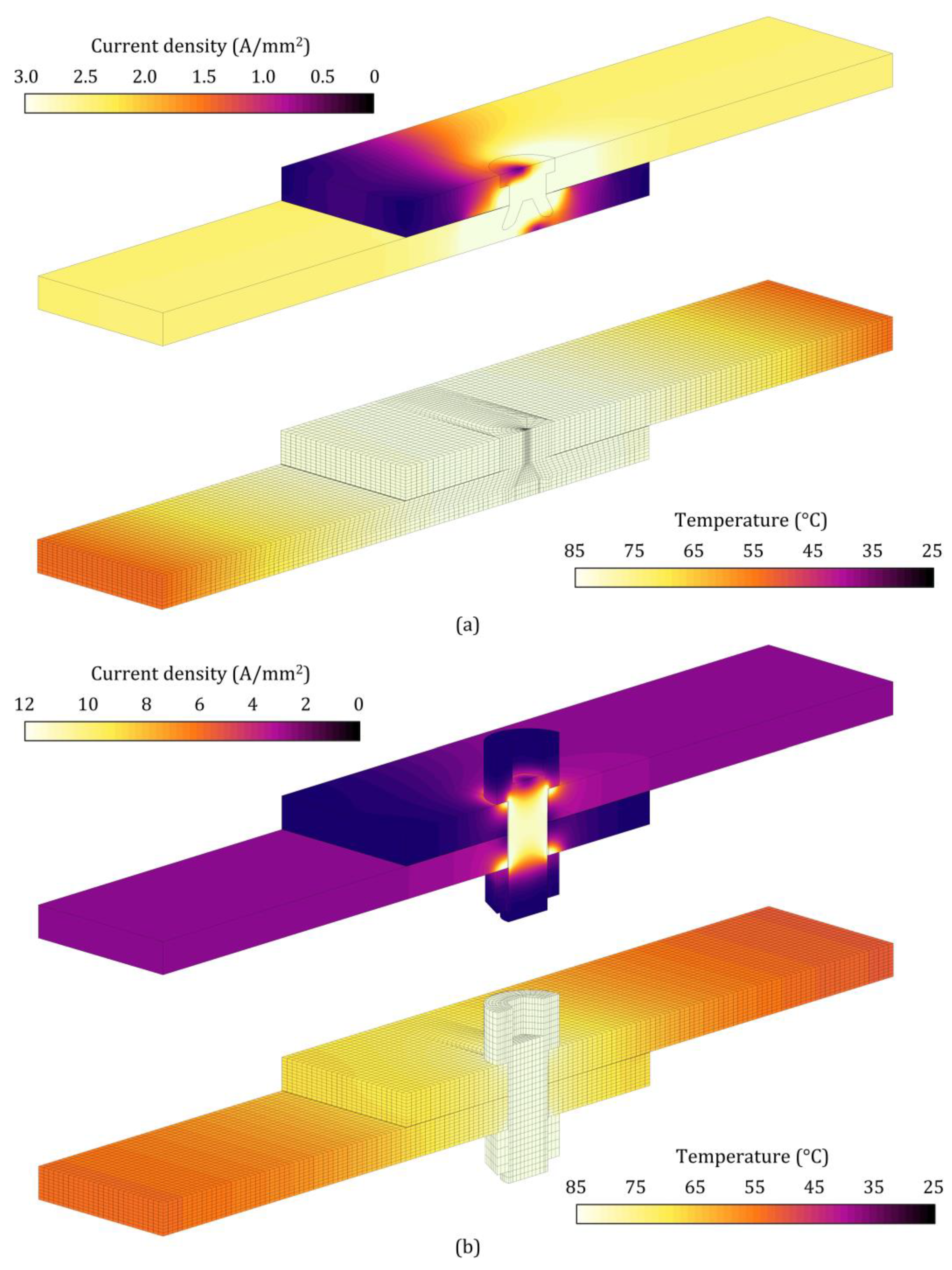
- Injection lap riveted joints built upon semi-tubular counterbored head rivets provide electrical resistances more than 3 times smaller than those of bolted joints due to the replacement of the steel bolts by aluminum rivets, causing smaller electric current disturbances.
- The sensitivity of the electrical resistance to temperature variations is also smaller for the injection lap riveted joints, which experience an increase of just 6 μΩ when the temperature is raised from 20 °C to 105 °C.
- Future developments must account for the differences between the in situ and the factory assembly of busbar systems because in the case of the latter, the new solution based on joining by sheet-bulk compression can provide electrical resistances 35% smaller than those obtained by the newly proposed injection lap riveting process.
Author Contributions
Funding
Institutional Review Board Statement
Informed Consent Statement
Data Availability Statement
Acknowledgments
Conflicts of Interest
References
- YCharts. Available online: http://ycharts.com/indicators/copper_price (accessed on 26 May 2022).
- Sampaio, R.F.; Zwicker, M.F.; Pragana, J.P.; Bragança, I.M.; Silva, C.; Nielsen, C.V.; Martins, P.A. Busbars for e-mobility: State-of-the-art review and a new joining by forming technology. In Mechanical and Industrial Engineering: Historical Aspects and Future Directions; Davim, J.P., Ed.; Springer: Berlin, Germany, 2022; pp. 111–141. [Google Scholar]
- Bao, Y.J.; Cheng, K.W.E.; Ding, K.; Wang, D.H. The study on the busbar system and its fault analysis. In Proceedings of the 5th International Conference on Power Electronics Systems and Applications (PESA), Hong Kong, China, 11–13 December 2013; pp. 1–7. [Google Scholar]
- Tzeneva, R.; Slavtchev, Y.; Mladenov, V. New connection design of high-power bolted busbar connections. In Proceedings of the 11th WSEAS International Conference on Circuits, Agios Nikolaos, Greece, 23–25 July 2007; pp. 228–233. [Google Scholar]
- Sampaio, R.F.V.; Pragana, J.P.M.; Bragança, I.M.F.; Silva, C.M.A.; Nielsen, C.V.; Martins, P.A.F. Electric performance of fastened hybrid busbars: An experimental and numerical study. J. Mater. Des. Appl. 2021, 236, 1152–1163. [Google Scholar] [CrossRef]
- Moustafa, G.; Grossmann, S.; Abdel-Salam, M.; Dessouky, S.S.; El-Makkawy, S.M. Joint resistance of bolted copper bus-bar connections as influenced by mechanical contact devices material and configuration. In Proceedings of the 13th Middle East Power Systems Conference (MEPCON), Assiut, Egypt, 20–23 December 2009; pp. 300–305. [Google Scholar]
- Chapman, D.; Norris, T. Copper for Busbars: Guidance for Design and Installation; Copper Development Association: New York, NY, USA, 2014; pp. 90–102. [Google Scholar]
- Rana, B.; Mallick, P.; Rana, T.K.; Basu, D.; Biswas, A.N.; Pramanik, S. Efficient and superior elbow joint for high power busway trunking system. In Proceedings of the 8th Annual Industrial Automation and Electromechanical Engineering Conference (IEMECON), Bangkok, Thailand, 16–18 August 2017; pp. 16–21. [Google Scholar]
- Katayama, S. Introduction: Fundamentals of laser welding. In Handbook of Laser Welding Technologies; Katayama, S., Ed.; Woodhead Publishing: Cambridge, UK, 2013; pp. 3–16. [Google Scholar]
- Moschinger, M.; Mittermayr, F.; Enzinger, N. Influence of beam figure on porosity of electron beam welded thin-walled aluminum plates. Materials 2022, 15, 3519. [Google Scholar] [CrossRef] [PubMed]
- Xu, B.; Tashiro, S.; Jiang, F.; Chen, S.; Manabu, T. Effect of arc pressure on the digging process in variable polarity plasma arc welding of A5052P aluminum alloy. Materials 2019, 12, 1071. [Google Scholar] [CrossRef] [PubMed] [Green Version]
- Schmidt, P.A.; Schweier, M.; Zaeh, M.F. Joining of lithium-ion batteries using laser beam welding: Electrical losses of welded aluminum and copper joints. In Proceedings of the ICALEO—International Congress on Applications of Lasers & Electro-Optics, Temecula, CA, USA, 23–27 September 2012; pp. 915–923. [Google Scholar]
- Ferreira, F.R.; Pragana, J.P.M.; Bragança, I.M.F.; Silva, C.M.A.; Nielsen, C.V.; Martins, P.A.F. Injection lap riveting. CIRP Ann. Manuf. Technol. 2021, 70, 261–264. [Google Scholar] [CrossRef]
- Braunovic, M. Effect of connection design on the contact resistance of high power overlapping bolted joints. IEEE Trans. Compon. Packag. Technol. 2002, 25, 642–650. [Google Scholar] [CrossRef]
- Melsom, S.W.; Booth, H.C. The efficiency of overlapping joints in copper and aluminium busbar conductors. J. Inst. Electr. Eng. 1922, 60, 889–899. [Google Scholar] [CrossRef]
- ASTM E8/E8 M; Standard Test Methods for Tension Testing of Metallic Materials. ASTM International: West Conshohocken, PA, USA, 2016.
- ISO 898-1:2013; Mechanical Properties of Fasteners Made of Carbon Steel and Alloy Steel-Part 1: Bolts, Screws and Studs with Specified Property Classes-Coarse Thread and Fine Pitch Thread. ISO—International Organization for Standardization: Geneva, Switzerland, 2013.
- ISO 898-2:2012; Mechanical Properties of Fasteners Made of Carbon Steel and Alloy Steel-Part 2: Nuts with Specified Property Classes-Coarse Thread and Fine Pitch Thread. ISO—International Organization for Standardization: Geneva, Switzerland, 2012.
- IEEE Std C37.20.2; IEEE Standard for Metal-Clad Switchgear. IEEE Power and Energy Society: New York, NY, USA, 2015.
- Kumar, N.; Masters, I.; Das, A. In-depth evaluation of laser-welded similar and dissimilar material tab-to-busbar electrical interconnects for electric vehicle battery pack. J. Manuf. Processes 2021, 70, 78–96. [Google Scholar] [CrossRef]
- MatWeb. Available online: https://www.matweb.com (accessed on 1 May 2022).
- Nielsen, C.V.; Martins, P.A.F. Finite element flow formulation. In Metal Forming: Formability, Simulation and Tool Design; Academic Press: London, UK, 2021; pp. 181–249. [Google Scholar]
- Studer, F.J. Contact resistance in spot welding. Weld. J. 1939, 18, 374–380. [Google Scholar]
- Reichel, A.; Sampaio, R.; Pragana, J.; Bragança, I.; Silva, C.; Martins, P. Form-fit joining of hybrid busbars using a flexible tool demonstrator. Proc. Inst. Mech. Eng. Part L J. Mater. Des. Appl. 2021, 236, 1164–1175. [Google Scholar] [CrossRef]


| Strips |  | ||||||||
| AA1050-H111 aluminum | 100 × 50 × 5 (mm3) | ||||||||
| Surface preparation | As supplied | ||||||||
| Injection lap riveted joints |  | ||||||||
| Counterbored rivet | Countersunk rivet | Dovetail hole | |||||||
| Process parameters | (mm) | (mm) | (mm) | (mm) | (mm) | (mm) | (°) | (mm) | (mm) |
| 2.1 ± 0.1 | 6.6 ± 0.1 | 11.3, 11.8 | 2 | 3 | 4.3–7.9 | 15, 30 | 3, 4 | 2.3 ± 0.1 | |
| Bolted joints |  | ||||||||
| Process parameters | Material | Size | Tightening torque (Nm) | ||||||
| Medium carbon steel (class 8.8) | M8 | 20 | |||||||
| AA1050-H111 | AA1050-O | Steel (Class 8.8) | |
|---|---|---|---|
| Elastic modulus (GPa) | 69 | 69 | 205 |
| Poisson ratio | 0.33 | 0.33 | 0.29 |
| Yield strength (MPa) | 34 | 28 | 640 |
| Ultimate tensile strength (MPa) | 83 | 76 | 800 |
| Stress-strain curve (MPa) | - |
Publisher’s Note: MDPI stays neutral with regard to jurisdictional claims in published maps and institutional affiliations. |
© 2022 by the authors. Licensee MDPI, Basel, Switzerland. This article is an open access article distributed under the terms and conditions of the Creative Commons Attribution (CC BY) license (https://creativecommons.org/licenses/by/4.0/).
Share and Cite
Pragana, J.P.M.; Sampaio, R.F.V.; Bragança, I.M.F.; Silva, C.M.A.; Martins, P.A.F. Injection Lap Riveting of Aluminum Busbars—A Thermo-Electro-Mechanical Investigation. J. Manuf. Mater. Process. 2022, 6, 74. https://doi.org/10.3390/jmmp6040074
Pragana JPM, Sampaio RFV, Bragança IMF, Silva CMA, Martins PAF. Injection Lap Riveting of Aluminum Busbars—A Thermo-Electro-Mechanical Investigation. Journal of Manufacturing and Materials Processing. 2022; 6(4):74. https://doi.org/10.3390/jmmp6040074
Chicago/Turabian StylePragana, João P. M., Rui F. V. Sampaio, Ivo M. F. Bragança, Carlos M. A. Silva, and Paulo A. F. Martins. 2022. "Injection Lap Riveting of Aluminum Busbars—A Thermo-Electro-Mechanical Investigation" Journal of Manufacturing and Materials Processing 6, no. 4: 74. https://doi.org/10.3390/jmmp6040074