
Further Study on One of the Numerical Methods for Pure Loss of Stability in Stern Quartering Waves


1
China Ship Scientific Research Center, Wuxi 214082, China
2
Maritime Safety Research Centre, University of Strathclyde, Glasgow G4 0LZ, UK
*
Author to whom correspondence should be addressed.
J. Mar. Sci. Eng. 2023, 11(2), 394; https://doi.org/10.3390/jmse11020394
Submission received: 2 January 2023
/
Revised: 5 February 2023
/
Accepted: 8 February 2023
/
Published: 10 February 2023
(This article belongs to the Topic Ship Dynamics, Stability and Safety)
Abstract
:The International Maritime Organization (IMO) finalized the second-generation intact stability criteria in 2022. However, an accurate and practical numerical method for stability loss has yet to be established. Therefore, a 6 DOF numerical model is further improved based on the previous study. Firstly, the rolling motion is simulated using a seakeeping model instead of the previous maneuvering mathematical model. Secondly, the roll-restoring variation is calculated directly considering the instantaneous wet hull instead of the previous pre-calculated method. Thirdly, transferring frequency to time is used to obtain heave and pitch motions, further considering yaw angle and sway velocity. Fourthly, the dynamic forces for sway, roll, and yaw motions are calculated, further considering the effect of the speed variation. Fifthly, the 6 DOF motions are used to determine the instantaneous wet hull, and the FK force and the hydrostatic force are calculated by the body’s exact method. Finally, a new conclusion is obtained that the sway and yaw motions’ effect on the ship speed loss, the relative longitudinal wave profile by the speed loss, the rudder angles, and the accompanying rudder forces in the rolling direction are significant, and much more than their centrifugal force or coupled force in the rolling direction.
1. Introduction
Dynamic stability failure modes could happen when the ship sails in the natural seas. The environment of the natural sea is complicated, and the existing intact stability code cannot guarantee the safety of the ship in the natural sea. For improving the safety level of the ship in the actual seas, the interim guideline on the second-generation intact stability criteria was approved by the International Maritime Organization (IMO) on 10 December 2020 [1], and her explanatory notes were finalized by the IMO in 2022 [2]. Five stability failure modes, including dead ship condition, pure loss of stability, parametric rolling, surf-riding/broaching, and excessive acceleration, three levels, including vulnerable Level 1, Level 2, direct assessment, and operational guidance, are considered in the stability criteria. An accurate numerical method is crucial for predicting stability failure modes directly. However, the physics of the failure modes had not yet been well understood, especially since there is still a dispute on the definition of pure loss of stability in stern quartering waves. An accurate and practical numerical method for stability loss has yet to be well established. Therefore, a mathematical model established previously by the authors [3] is further improved for calculating stability loss directly.
In the early stage, pure loss of stability is considered as the loss of a static roll-restoring arm in waves at the crest by some pioneer researchers, such as Paulling [4,5], Hamamoto and Nomoto [6], and Kuo and Vassalos [7], and their studies focused on how to calculate the roll-restoring arm in waves. Therefore, the vulnerable Level 1 and Level 2 criteria of pure loss of stability are drafted based on the roll-restoring arm in waves.
The natural sea is a random wave, and the stochastic process of stability loss in irregular waves is studied by Dunwoody [8], and Bulian and Francescutto [9]. The methods of failure probability are studied at this stage. The Grim effective wave is used by Umeda and Yamakoshi [10], a narrow-banded stochastic process is studied by Vermeer [11], the “critical wave” is used by Themelis and Spyrou [12], the up-crossing theory is used by Bulian et al. [13], and the split-time method is used by Belenky et al. [14].
With the development of hydrodynamics and the improvement of human cognition, stability loss is considered a capsizing mode of significant time-domain roll motion due to the lost roll-restoring arm at the crest and the staying time at the crest. Bassler pointed out that stability loss is not limited to the loss of the roll-restoring arm at the crest [15]. Some numerical methods for stability loss are reviewed by Neves [16]. A surge-roll coupled mathematical model for pure loss of stability in following seas was developed by Hashimoto [17], and the heave and pitch motions were further added by the authors, and a conclusion is confirmed that a small heeling angle should be set in the numerical simulations and the experiments for stability loss in following seas [18]. The time-domain simulation begins to be carried out in this stage.
With the improvement of human cognition, stability loss is considered not “pure” in astern waves. A new conclusion is pointed out by Umeda that the maneuvering sway and yaw motions could be the reason for the large rolling in stern quartering waves, and stability loss could not be pure [19,20]. Following that, their new mathematical model was submitted to IMO [21]. As a result, at least 4 DOF mathematical models are requested by IMO for predicting pure loss of stability in the time domain.
The significant rolling motion during stability loss is predicted by Liu et al. [22] using the CFD software/method, and their results are compared with the author’s experimental results in the reference [3]. However, the practical application of the CFD method in engineering is limited because a considerable time could be costly compared to the potential method. The vulnerable criteria produce conservative results, and their methods are much simpler than the direct numerical predicting method in the time domain. In addition, the vulnerable criteria of pure loss of stability are studied by some researchers [23,24,25].
The numerical methods without standard expressions could not be used in general. Therefore, a standard maneuvering prediction method is presented by Yasukawa and Yoshimura [26]. Some broaching prediction methods are given out by Hashimoto et al. [27] and Umeda et al. [28] based on the maneuvering prediction methods. Based on the maneuvering and broaching prediction methods, the first author tried to establish a surge-sway-roll-pitch (4 DOF) standard numerical method for predicting stability loss in astern waves [29,30]. As a result, a numerical method with surge-sway-heave-roll-pitch-yaw coupled is established. However, the roll-restoring arm in waves is pre-calculated, taking heave and pitch motions into account [3].
Stability loss is a complicated wave phenomenon, and nonlinear dynamics can be used to study its mechanics [31]. However, time-domain stability loss in astern seas is related to the ship’s maneuvering force, the rudder force, and the body’s exact roll-restoring force in waves. Therefore, it is still challenging to predict stability loss accurately in the time domain. Therefore, a 6 DOF numerical model is further established based on the previous research [3].
The improvement includes the following aspects: (1) The roll-restoring arm in waves is pre-calculated, taking heave and pitch motions into account in the previous research [3], and the mathematical model can be regarded as a 4 DOF model. In contrast, the roll-restoring arm in waves is calculated considering the instantaneous wet hull determined by 6 DOF ship motions, and the mathematical model can be regarded as a 6 DOF model. (2) The roll motion is simulated using a time-domain seakeeping model instead of the previous maneuvering mathematical mode. (3) The body’s exact FK and hydrostatic forces in the rolling direction are calculated directly, referring to the numerical method for parametric roll [32,33,34], and the body’s exact FK forces in the swaying and yawing direction are calculated directly. (4) The diffraction forces and radiation forces are calculated with a two-dimensional vectorizing method and an enhanced strip method at several constant speeds, and the speed-varied diffraction forces and radiation forces are considered by an interpolation method. (5) The speed loss due to the significant yaw motion is noted in this paper. (6) The roll-restoring arms’ comparison at both the starboard and port, and the different components of the restoring force variations GZW_FK + B, GZW_FK, and GZW_B are given out in this paper. (7) The numerical maximum roll angels at both the starboard and port are compared with the experimental results, and a good agreement is realized in this paper, while only the maximum roll angels at the port were given out with a large error compared with the experimental results in the previous research [3]. (8) The new phenomena of subharmonic rolling and yaw-roll coupling during pure loss of stability are defined in this paper. (9) A new conclusion about the sway and yaw motions’ effect on pure loss of stability is obtained.
2. Mathematical Model
2.1. Coordinate Systems
A horizontal body coordinate system was developed by Hamamoto and Kim [35] for studying stability in waves, and the coordinate system is shown in Figure 1. Their relations are shown in the authors’ previous reference [3]. The ship heading angle is , and the heading angle of the incident wave is added to the coordinate system. The instantaneous heading angle takes the yaw motion into account.
2.2. Mathematical Model
The ship motion is six degrees of freedom (DOF) in the real seas, and the mathematical model with different DOF is used for the engineering application. The mathematical model with 6 DOF is also used by many researchers. However, the dynamic stability failure models in waves are nonlinear phenomena. The nonlinear significant rolling motion during stability loss in astern waves is related to seakeeping, maneuvering, stability, thrust, and speed loss in waves, and few mathematical models can be utilized to predict stability loss perfectly. An improved 6 DOF mathematical model for predicting stability loss in astern waves is presented as follows. Equation (1) is the time-domain surge motion. The sway and yaw motions are maneuvering mathematical models for the course keeping, as shown in Equations (2) and (4). For using maneuvering hull forces as few as possible in the roll motion, Equation (3) is the time-domain roll motion with the seakeeping model instead of the previous maneuvering mathematical model in the author’s reference [3]. When a ship advances in astern waves with a high forward speed while the wavelength is near equal to the ship length, the encountered frequency could be very low, even zero. The radiation coefficients could be divergent at a low encountered frequency. Therefore, the heave and pitch motion with a low encountered frequency could be divergent. Therefore, the frequency-domain heave and pitch motions are pre-calculated by an enhanced strip method developed by Kashiwagi [36,37]. Transferring frequency to time is used to obtain the heave and pitch motions, as shown in Equations (5)–(8). The yaw motion is not considered in the frequency-domain heave and pitch motions. However, the instantaneous heading with yaw angle and sway velocity are considered in the time domain, as shown in Equation (9), which is an improvement compared with the authors’ previous study in the reference [3].
Equation (10) is the control equation for course keeping.
The subscripts H, R, and P refer to the hull, rudder, and propeller, respectively. Note: the subscripts P in Equations (10) and (35) have different meanings.
The hydrodynamic force acting on a ship hull, the resistance in calm water, the propeller thrust, and the steering rudder forces are shown in the authors’ previous reference [3].
2.3. Excited Forces by the Wave
The body’s exact FK and hydrostatic forces in the roll direction should be taken into account for predicting parametric roll. The authors pre-calculate roll restoring variation for predicting stability loss in the previous study [3]. Here, the body’s exact FK and hydrostatic forces in the rolling direction are calculated directly. The body’s exact FK forces in the swaying and yawing direction are also calculated directly. In addition, the diffraction forces and radiation forces are calculated with a two-dimensional vectorizing method at several constant speeds, and the speed-varied diffraction forces and radiation forces are considered by an interpolation method. These are the improvements compared with the authors’ previous study in the reference [3].
A ship is advancing with a constant speed and oscillating with a circular frequency in deep water. With the assumption of linearized potential flow, the velocity potential and the excited wave forces and are given out by Kashiwagi et al. in the reference [36,37] and their seakeeping book according to the slender ship theory. The excited wave forces and are re-obtained detailed as follows, according to the reference [36,37]. denotes the component of the unit normal vector, and is the sectional contour at station . The method of subsection integration is used from step 2 to step 3 in Equation (13).
The lift force of the after and forward sections is also considered based on the strip theory.
2.4. Roll Restoring Force Variation
The roll-restoring arm GZW_FK + B, GZW_FK, and GZW_B based on the Froude–Krylov assumption can be defined as follows.
The similar symbols of GZ used in this paper are defined as follows.
2.5. Roll Damping Moment
The roll damping moment is calculated by Equation (21) with the linear and cubic roll damping coefficients denoted by and .
The roll damping coefficients are obtained by carrying out the rolling decay test.
2.6. Hull Forces in Still Water
Although the expressions of hull forces in still water are generally used for predicting ship maneuvering and broaching, for the system of the mathematical model in this paper, the expressions of the hull forces in still water , and are rewritten as follows by referring [26,28]. The unified expressions of the nondimensional maneuvering coefficients are rewritten by the authors in the reference [3], and the symbols of maneuvering coefficients are also shown in the reference [3]. The effect of the high-order coefficients on the surge motion is investigated by the authors, and its effect is generally small [3]. Therefore, only resistance is remained in . The seakeeping model of the roll motion is used in this paper, and only the heel-induced hydrodynamic force is considered in .
Nondimensional sway velocity , and yaw rate are expressed as follows:
2.7. Rudder Force
Rudder forces are essential parts of the mathematical model for pure loss of stability in stern quartering waves, and the rudder force in the rolling direction is focused on in this paper. Although the expressions of rudder forces are generally used for predicting ship maneuvering and broaching, for the system of the mathematical model in this paper, the expressions of rudder forces , and with twin rudders are rewritten as follows by referring [39]. The average values of , are used in this paper. (S: starboard; P: port)
2.8. Propeller Thrust and the Resistance in Still Water
The propeller thrust and the resistance in still water are used for time-domain surge motion, and the propeller thrust with twin propellers, and the hull resistance in still water is also given out as follows for the system of the mathematical model in this paper.
3. Experiments and Subject Ship
The ONR (The Office of Naval Research in USA) tumblehome hull used in the authors’ previous reference [3] is still used in this paper. The principal particulars and the system parameters of the ONR tumblehome are given out in Table 1 and Table 2.
The free-running experiment was conducted at China Ship Scientific Research Center, one member of the International Towing Tank Conference (ITTC) organization. The experiment of pure loss of stability was carried out in the seakeeping basin (length: 69 m, breadth: 46 m, depth: 4 m) according to the test guidelines in the ITTC.
The ship model was free running in astern waves with twin propellers and twin rudders. The 6 DOF optical fiber gyroscope was placed on the ship model to measure the roll, pitch, and yaw angles during the free running. An onboard system was connected to an onshore control computer by wireless to record the roll, pitch, yaw, rudder angles, and propeller rotation speed. A servo-needle wave height sensor was attached to a steel bridge which is 78 m in length and spans over the basin to measure the wave elevation at the middle of the basin. A total station system is used to record the position of the ship model with a specified propeller rate in calm water, and then one specified propeller rate corresponding to one nominal speed in calm water is obtained. The same specified propeller rate in calm water is used to achieve the same nominal speed in the free-running experiments in astern waves.
First, the model is kept with a zero forward speed and an initial heading angle near the wave maker manually by two workmen. Next, the waves are generated by the wave-making system. Then, the propeller rate is increased up to the specified value after receiving the order from the onshore control computer. Finally, the ship model is released free near one wave crest with its initial heading when the wave train propagates far enough, and then the model automatically runs in astern waves with its specified propeller rate and autopilot course.
A PD control system is used for course keeping which reacts according to the bias between the instantaneous heading angle measured by the gyroscope and the autopilot course, and the yaw velocity measured by the gyroscope. The rudder gain is set by the experience according to the reaction of course keeping in calm water.
4. Simulations and Discussions
The roll-restoring variation becomes significant when the wavelength is nearly equal to the ship length, and the surging amplitude becomes significant when the wavelength is larger than the ship length in astern waves. One wave condition is selected for study stability loss in astern waves, which is the same as that in the reference [3]. The wave condition is H/Lpp = 0.05 and λ/Lpp = 1.25. The autopilot heading is set with χC = 30 degrees. The following sections will not mention the wave condition repeatedly. Some other results are also submitted to IMO by the first author as a member of IMO [41,42,43,44,45]. However, the opinions expressed in this paper only reflect the academic research and do not reflect the views of China or UK.
4.1. Roll-Restoring Arm
The roll-restoring arms based on the Froude–Krylov assumption are calculated considering the instantaneous wet hull. The roll-restoring arms in the port are further studied compared with the authors’ previous study [3]. GZ_still is the righting arm in still water, GZW_FK + B_static is the roll-restoring arms in waves with a static balance method, and GZW_FK + B_Fn is the roll-restoring arms in waves with an enhanced strip method at different constant speeds. Here, the heeling angles of 10 degrees (starboard) and −10 degrees (port)are set, respectively. The GZ loss in the starboard is significant when the midship section is located on the crest, as shown in Figure 2a. In contrast, the GZ loss in the port is significant if the midship section is on the upslope, as shown in Figure 2b. This is one of the reasons why stability loss occurs on the upslope of the waves. The roll-restoring arms in the time domain will be further discussed in the next part.
The ship velocity without/with the yaw motion and wave celerity are shown in Figure 3a,b. The wave celerity is much faster than the ship forward speed. The actual forward speed is periodically varied with a significant amplitude around a mean speed when the surge motion is considered. The mean speed is nearly equal to the nominal speed without the yaw motion or with a small yaw motion, as shown in Figure 3a. In contrast, the average speed is significantly smaller than the speed in calm water with a large yaw motion at this condition, as given out in Figure 3b, because the effective thrusts in the heading direction become small due to the significant yaw motion. The discussion on speed loss due to the significant yaw motion is an improvement compared with the authors’ previous study [3].
GZ_still and GZW_FK + B with and without the surge are shown in Figure 4a,b. The different components of the roll-restoring arms GZW_FK and GZW_B are shown in Figure 5a,b. Here, the heeling angles of 10 and −10 degrees are set, respectively. The retention time at the crest could be extended by the surge motion. Therefore, the retention time of stability loss could be extended at the crest at the starboard. Figure 5b shows that the stability loss at the port is significant at the upslope of the waves. The hydrostatic force GZW_B is near the same at the starboard and port in astern seas with a heading of 30 degrees, as given out in Figure 5a, while the wave exciting FK force GZW_FK is significantly different at the starboard and port in astern seas with a heading of 30 degrees, as given out in Figure 5b. As we all know, the roll-restoring arms, including GZW_B, GZW_FK, and GZW_FK + B, should be the same at the starboard and port in following seas because the ship hull is symmetric to the center line, and the roll-restoring arm in waves becomes small at the crest and becomes large at the trough when the wavelength is near equal to the ship length in following seas because the roll-restoring arm is related with the area moment of waterplane and the waterplane becomes small at the crest and becomes large at the trough. However, the wave exciting FK force GZW_FK could be different in oblique waves. The main reason why the roll variation GZW_FK + B at the starboard in Figure 4a is significantly different from that at the port in Figure 4b is that the wave exciting FK force GZW_FK is significantly different at the starboard and port in astern seas with a heading of 30 degrees, as given out in Figure 5b. The comparison of the roll-restoring arms at both the starboard and port, and the different components of the restoring force variations GZW_FK + B, GZW_FK, and GZW_B are given out in this section which is an improvement compared with the authors’ previous study [3].
4.2. Contributions from Sway, Yaw, and Rudder
The contributions of some key elements in the rolling mathematical model to the roll moment are shown in Figure 6, Figure 7 and Figure 8 by comparing with the roll-restoring arms in waves GZW_FK + B. The results are simulated with constant heeling angles of 20 and −20 degrees, respectively. As shown in Figure 6, we can find that the rudder produces a significant negative contribution in the rolling direction. One of the reasons is that the value of is large due to a high gravity center with a small GM, as shown in Table 2. The second reason is that the rudder’s normal force is large with a high inflow velocity at a high forward speed. The third reason is that the yaw motion becomes large, and the rudder angle becomes essential to keep the course. The coupled sway force has a slightly negative contribution in the rolling direction, as given out in Figure 7, but the coupled yawing forces are not tiny, as given out in Figure 8, but their negative and positive contribution is nearly the same.
The comparisons of maximum roll angles during stability loss between mathematical models with and without the sway and yaw motions are conducted. The 6 DOF numerical method can predict the roll angle, as given out in Figure 9a. In comparison, the 4 DOF numerical method underestimates the roll angle without the sway and yaw motions. This is because the 4 DOF method, ignoring the sway and yaw motions, means the rudder force is also ignored with zero rudder angle at a constant heading angle. However, the rudder force is a crucial factor for stability loss at high ship speeds, as given out in Figure 6. The effect of the coupled sway and yaw force on the maximum roll angles during stability loss is generally small, as shown in Figure 10a,b. Because the coupled sway and yaw force in the rolling direction is insignificant, as shown in Figure 7 and Figure 8. That is to say, the sway and yaw motions’ effect on stability loss comes from the rudder force because the yaw motion and the rudder angle are significant. The rudder angle is larger than 15 degrees to keep the course, as shown in Figure 11. The significant yaw motion also affects the surge force and the thrust in the heading direction, and the speed lost is significant, as given out in Figure 3b. Then the relative wave profiles are affected.
Therefore, the mathematical model should take the sway and yaw motions into account. Their effects on the ship speed loss, the relative longitudinal wave profile due to the speed loss, the rudder angle, and accompanying rudder forces in the rolling direction are significant and much more than their coupled or centrifugal force in the rolling direction.
4.3. New Phenomenon during Pure Loss of Stability
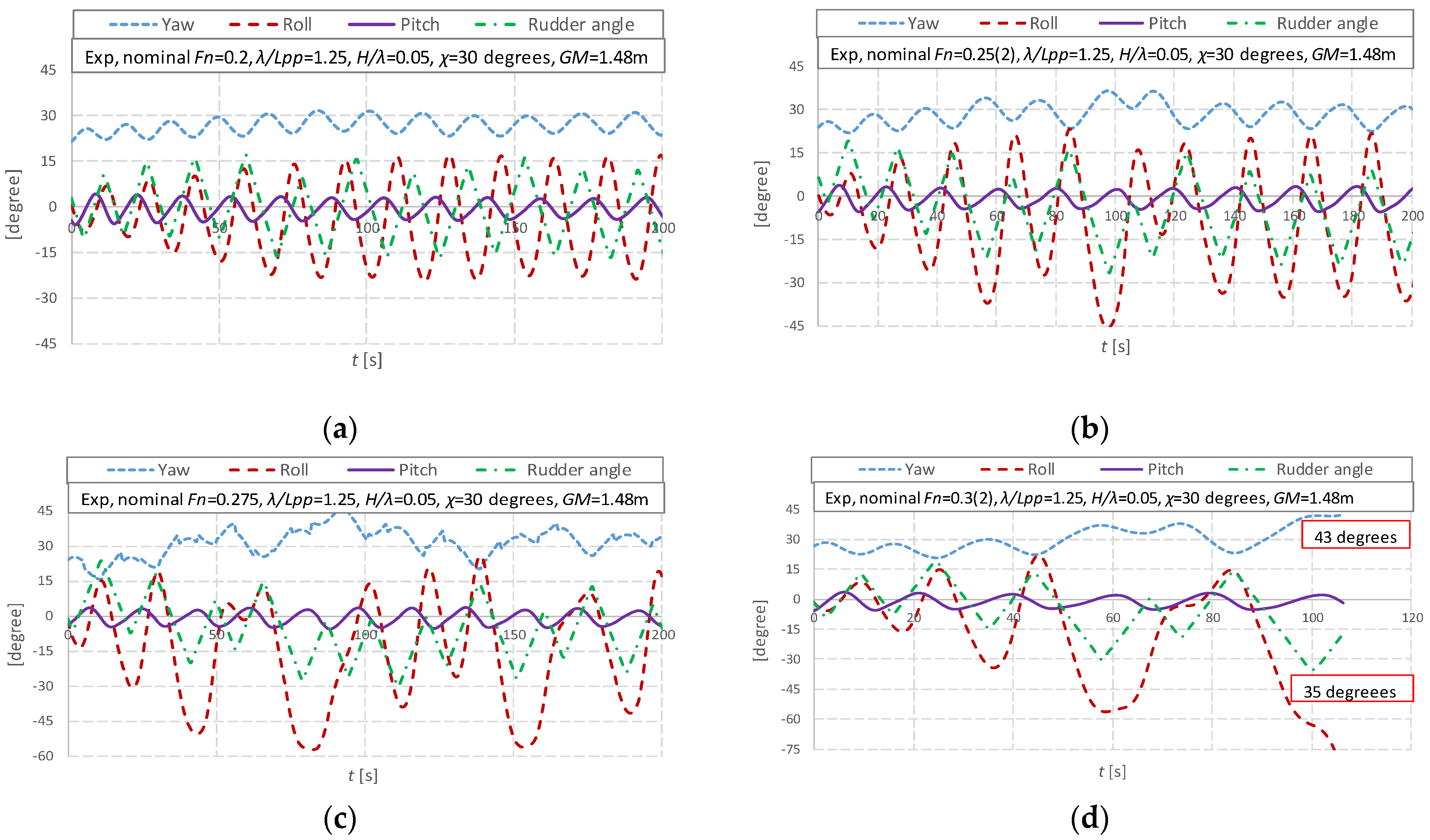
The time-domain rolling, pitching, yawing motions, and rudder angle in the tests are analyzed. Figure 11a shows a periodic stable rolling motion, while Figure 11b shows an unstable rolling motion. Figure 11c shows that the fourth and the seventh roll periods are two times the encounter period, which means subharmonic rolling occurs during stability loss. This phenomenon was also observed by Kan et al. [46] and named period bifurcation. The significant roll developments toward the port occur with the large starboard yaw angle in Figure 11d. The ship heading angle is 43 degrees, and the rudder angle is the maximum of 35 degrees to keep course during the ship capsizing, as shown in Figure 11d, and this could be a typical pattern of capsizing due to yaw-roll coupling with loss of stability.
The 6 DOF time-domain ship motions are calculated with the numerical method mentioned in this paper. The 6 DOF numerical method can predict the maximum rolling angles, as given out in Figure 12. However, the new phenomenon during stability loss, such as unstable rolling motion and subharmonic rolling, still cannot be captured by the numerical method.
The above discussion considers the rolling motion in the starboard and port with the improved 6 DOF numerical method, which is also an improvement, while the previous study [3] only considers the port.
5. Conclusions
The mathematical model of stability loss is updated based on the authors’ previous mathematical model, and the following remarks can be made:
- (1)
- The actual forward speed should be considered by the surge motion.
- (2)
- The yaw motion is significant and results in a ship speed loss which affects the relative longitudinal wave profile in the time domain. The rudder angles are substantial due to the considerable yaw motion, and then the rudder forces in the rolling direction are significant. The above effects from the coupled sway and yaw motion are much more than their centrifugal or coupled force in the rolling direction.
- (3)
- This paper’s improved 6 DOF mathematical model can be utilized for stability loss in astern waves at this stage.
As unstable rolling motions, subharmonic rolling and yaw-roll coupling could exist during stability loss, and some research could be carried out on these complicated phenomena.
Author Contributions
Conceptualization, J.L. and E.B.; methodology, J.L. and M.G.; software, J.L.; validation, J.L. and M.G.; formal analysis, J.L., M.G. and E.B.; writing—original draft preparation, J.L.; writing—review and editing, E.B. All authors have read and agreed to the published version of the manuscript.
Funding
This research was funded by Ministry of Industry and Information Technology of China, grant number No. [2016] 25, 26; [2017]614.
Acknowledgments
Some contents used in this research were once guided by Naoya Umeda during the first author’s Ph.D. course at Osaka University supported by China Scholarship Council [No.2008606031]. The new phenomena of subharmonic rolling and yaw-roll coupling during pure loss of stability are defined in this paper by discussing with Naoya Umeda. This paper is a further study based on the paper [3] which was finished during the first author’s visiting at University of Strathclyde supported by China Scholarship Council [No.201905280001]. These supports are gratefully acknowledged. Boulougouris work was supported from DNVGL and RCCL, sponsors of the MSRC. The opinions expressed herein are those of the authors and do not reflect the views of DNVGL and RCCL.
Conflicts of Interest
The authors declare no conflict of interest.
List of Symbols
| coupling seakeeping coefficients | |
| coupling seakeeping coefficients at the x section | |
| Rudder force increase factor | |
| After section and forward section | |
| Rudder area | |
| The port and starboard rudder area | |
| Sectional breadth | |
| Total resistance coefficient in calm water | |
| Wave celerity | |
| Ship draft | |
| Sectional draught | |
| Propeller diameter | |
| Roll damping moment | |
| Froude–Krylov force in the j direction | |
| Diffraction force in the j direction | |
| Hydrostatic force in the j direction | |
| Rudder normal force | |
| Froude number based on ship length | |
| Rudder lifting slope coefficient | |
| Gravitational acceleration | |
| Metacentric height | |
| Rudder span length | |
| Moment of inertia in roll, pitch, and yaw | |
| Propeller advanced ratio | |
| Wave number | |
| Rudder gain | |
| Thrust coefficient of the propeller | |
| Ship length for integration | |
| Ship length between perpendiculars | |
| Correction factor for flow-straightening due to yaw | |
| Ship mass | |
| Propeller revolution number | |
| Roll rate | |
| Yaw rate | |
| Ship resistance | |
| Sectional area | |
| Wetted hull surface area | |
| Sectional line for sectional integration | |
| Thrust deduction factor | |
| Steering resistance deduction factor | |
| Propeller thrust | |
| The time constant for the steering gear | |
| The time constant for differential control | |
| Natural roll period | |
| Surge and sway velocity of the ship hull | |
| Inflow velocity to the rudder in the surge and sway direction | |
| Ship forward velocity | |
| Wake fraction at propeller position and rudder position | |
| Ship weight | |
| Longitudinal/vertical position of additional sway force due to the rudder | |
| Longitudinal/vertical position of the rudder | |
| Hull force in the surge, sway, yaw, and roll direction in calm water | |
| Rudder force in the surge, sway, yaw, and roll direction | |
| Effective inflow angle to the rudder | |
| Hull drift angle | |
| Rudder angle | |
| Initial phase of the j mode ship motion | |
| The ratio of propeller diameter to rudder span | |
| The ratio of wake fraction at the propeller and rudder position | |
| Propeller-induced flow velocity factor | |
| Wavelength | |
| Ruder aspect ratio | |
| Flow-straightening effect coefficient | |
| Roll and pitch angle | |
| Potential of incident waves | |
| Potential of radiation waves in the j direction | |
| Potential of diffraction waves | |
| Instantaneous ship heading angle considering the yaw motion | |
| Autopilot course or constant ship heading | |
| Water density | |
| Wave frequency and encounter frequency | |
| Longitudinal position of the center of ship gravity from a wave trough | |
| Position of center of ship gravity in the space-fixed coordinate system | |
| Wave amplitude | |
| 1: surge; 2: sway; 3: heave; 4: roll; 5: pitch; 6: yaw |
References
- IMO. Interim Guidelines on the Second Generation Intact Stability Criteria; Msc.1/Circ.1627; IMO: London, UK, 2020. [Google Scholar]
- IMO. Development of Explanatory Notes to the Interim Guidelines on Second Generation Intact Stability Criteria; SDC 8/WP.4. Report of the Drafting Group; IMO: London, UK, 2022. [Google Scholar]
- Lu, J.; Gu, M.; Boulougouris, E. Model experiments and direct stability assessments on pure loss of stability in stern quartering waves. Ocean Eng. 2020, 216, 108035. [Google Scholar] [CrossRef]
- Paulling, J.R. The transverse stability of a ship in a longitudinal seaway. J. Ship Res. 1961, 44, 37–49. [Google Scholar]
- Paulling, J.R.; Oakley, O.H.; Wood, P.D. Ship capsizing in heavy seas: The correlation of theory and experiments. In Proceedings of the 1st International Conference on Stability of Ships and Ocean Vehicle, Glasgow, UK, 24–27 March 1975. [Google Scholar]
- Hamamoto, M.; Nomoto, K. Transverse Stability of Ships in a Following Sea. In Proceedings of the 2nd International Conference on Stability of Ships and Ocean Vehicles, Sasakawa Hall, Tokyo, Japan, 24–29 October 1982; pp. 215–224. [Google Scholar]
- Kuo, C.; Vassalos, D.; Alexander, J.G. Incorporating theoretical advances in usable ship stability criteria. In Proceedings of the RINA International Conference on the Safeship Project—Ship Stability and Safety, London, UK, 9–10 June 1986. [Google Scholar]
- Dunwoody, A.B. Roll of a ship in Astern Seas-metacentric height spectra. J. Ship Res. 1989, 33, 221–228. [Google Scholar] [CrossRef]
- Bulian, G.; Francescutto, A. On the effect of stochastic variations of restoring moment in long-crested irregular longitudinal sea. In Proceedings of the 9th International Conference on Stability of Ships and Ocean Vehicle, Rio de Janeiro, Brazil, 25–29 September 2006; Volume 1, pp. 131–146. [Google Scholar]
- Umeda, N.; Yamakoshi, Y. Probability of ship capsizing due to pure loss of stability in quartering seas. Nav. Archit. Ocean Eng. Sel. Pap. Soc. Nav. Arch. Jpn. 1993, 30, 73–85. [Google Scholar] [CrossRef]
- Vermeer, H. Loss of stability of ships in following waves in relation to their design characteristics. In Proceedings of the 4th International Conference on Stability of Ships and Ocean Vehicles, Naples, Italy, 24–28 September 1990. [Google Scholar]
- Themelis, N.; Spyrou, K.J. Probabilistic assessment of ship stability trans. SNAME 2007, 115, 181–206. [Google Scholar]
- Bulian, G.; Francescutto, A.; Maccari, A. Possible Simplified Mathematical Models for Roll Motion in the Development of Performance-Based Intact Stability Criteria–Extended and Revised Version; University of Trieste: Trieste, Italy, 2008. [Google Scholar]
- Belenky, V.; Weems, K.; Lin, W.-M. Split-time method for estimation of probability of capsizing caused by pure loss of stability. In Proceedings of the 12th International Conference on Stability of Ships and Ocean Vehicles, Glasgow, UK, 19–24 June 2015. [Google Scholar]
- Bassler, C.; Belenky, V.; Bulian, G.; Francescutto, A.; Spyrou, K.; Umeda, N. Review of Available Methods for Application to Second Level Vulnerability Criteria. Contemp. Ideas Ship Stab. Capsizing Waves 2011, 97, 3–23. [Google Scholar]
- Neves, M. Dynamic stability of ships in regular and irregular seas—An overview. J. Ocean Eng. 2016, 120, 362–370. [Google Scholar] [CrossRef]
- Hashimoto, H. Pure Loss of Stability of a Tumblehome Hull in Following Seas. In Proceedings of the 19th International Offshore and Polar Engineering Conference, Osaka, Japan, 21–26 June 2009. [Google Scholar]
- Lu, J.; Gu, M.; Boulougouris, E. Model Experiments and Direct Stability Assessments on Pure Loss of Stability of the ONR Tumblehome in Following Seas. Ocean Eng. 2019, 194, 106640. [Google Scholar] [CrossRef]
- Kubo, H.; Umeda, N.; Yamane, K.; Matsuda, A. Pure Loss of Stability in Astern Seas—Is It Really Pure? In Proceedings of the 6th Asia-Pacific Workshop on Marine Hydrodynamics, Johor, Malaysia, 3–4 September 2012; pp. 307–312. [Google Scholar]
- Umeda, N.; Osugi, M.; Ikenaga, Y.; Matsuda, A. Pure loss of stability in stern quartering waves: Revisited with numerical simulations reproducing accidents. In Proceedings of the 17th International Ship Stability Workshop, Helsinki, Finland, 10–12 June 2019. [Google Scholar]
- IMO. Development of Second Generation Intact Stability Criteria; SLF 55/INF.15.Annex 12; IMO: London, UK, 2013. [Google Scholar]
- Liu, L.; Feng, D.; Wang, X.; Zhang, Z.; Yu, J.; Chen, M. Study on extreme roll event with capsizing induced by pure loss of stability for the free-running ONR Tumblehome. Ocean Eng. 2022, 2557, 111656. [Google Scholar] [CrossRef]
- Petacco, N.; Pitardi, D.; Bonvino, C.P.; Gualeni, P. Application of the IMO Second Generation Intact Stability Criteria to a Ballast-Free Containership. J. Mar. Sci. Eng. 2021, 9, 1416. [Google Scholar] [CrossRef]
- Marlantes, K.; Kim, S.; Hurt, L. Implementation of the IMO Second Generation Intact Stability Guidelines. J. Mar. Sci. Eng. 2022, 10, 41. [Google Scholar] [CrossRef]
- Rinauro, B.; Begovic, E. Vulnerability assessment of surf-riding-broaching and pure loss of stability for Systematic Series D1 model. Ships Offshore Struct. 2019, 14, 1–7. [Google Scholar] [CrossRef]
- Yasukawa, H.; Yoshimura, Y. Introduction of MMG Standard Method for Ship Maneuvering Predictions. J. Mar. Sci. Technol. 2015, 20, 37–52. [Google Scholar] [CrossRef] [Green Version]
- Hashimoto, H.; Umeda, N.; Matsuda, A. Broaching Prediction of a Wave-piercing Tumblehome Vessel with Twin screws and Twin Rudders. J. Mar. Sci. Technol. 2011, 16, 448–461. [Google Scholar] [CrossRef]
- Umeda, N.; Usada, S.; Mizumoto, K.; Matsuda, A. Broaching Probability for a Ship in Irregular Stern-quartering Waves: Theoretical Prediction and Experimental Validation. J. Mar. Sci. Technol. 2016, 21, 23–37. [Google Scholar] [CrossRef]
- Lu, J.; Gu, M. Study on Standard Mathematical Model of Pure Loss of Stability in Stern-quartering Waves. In Proceedings of the 16th International Ship Stability Workshop, Belgrade, Serbia, 5–7 June 2017. [Google Scholar]
- Lu, J.; Gu, M.; Wang, T.H.; Shi, C. Experimental and Numerical Study on Standard Mathematical Model for Pure Loss of Stability. In Proceedings of the 13th International Conference on Stability of Ships and Ocean Vehicles, Kobe, Japan, 16–21 September 2018. [Google Scholar]
- Spyrou, K.J. Dynamic instability in quartering seas-Part III: Nonlinear effects on periodic motions. J. Ship Res. SNAME 1997, 41, 210–223. [Google Scholar] [CrossRef]
- Lu, J.; Gu, M.; Umeda, N. A Study on the Effect of Parametric Rolling on Added Resistance. Ocean Eng. 2016, 122, 288–292. [Google Scholar] [CrossRef]
- Lu, J.; Gu, M.; Umeda, N. Experimental and Numerical Study on Several Crucial Elements for Predicting Parametric Roll in Regular Head Seas. J. Mar. Sci. Technol. 2017, 22, 25–37. [Google Scholar] [CrossRef]
- Umeda, N.; Fujita, N.; Morimoto, A.; Sakai, M. Numerical Prediction of Parametric Roll Resonance in Oblique Waves. In Proceedings of the 12th International Conference on Stability of Ships and Ocean Vehicle, Glasgow, Scotland, 19–24 June 2015. [Google Scholar]
- Hamamoto, M.; Kim, Y.S. A New Coordinate System and the Equations Describing Manovering Motion of a Ship in Waves. J. Soc. Nav. Archit. Jpn. 1993, 173, 209–220. [Google Scholar] [CrossRef]
- Kashiwagi, M. Prediction of Surge and Its Effect on Added Resistance by Means of the Enhanced Unified Theory. Trans West-Jpn. Soc. Nav. Arch. 1995, 89, 77–89. [Google Scholar]
- Kashiwagi, M.; Ikeda, T.; Sasagawa, T. Effect of Forward Speed of a ship on Added Resistance in waves. Int. J. Offshore Polar Eng. 2010, 20, 1–8. [Google Scholar]
- Himeno, Y. Roll damping. In Second Symposium on Seakeeping; Japan Society of Naval Architects and Ocean Engineers: Tokyo, Japan, 1977; Volume 1–21, p. 199. (In Japanese) [Google Scholar]
- Khanfir, S.; Hasegawa, K.; Nagarajan, V.; Shouji, K.; Lee, S.K. Maneuvering Characteristics of Twin-rudder systems: Rudder-hull Interaction Effect on the Maneuverability of Twin-rudder Ships. J. Mar. Sci. Technol. 2011, 16, 472–490. [Google Scholar] [CrossRef]
- Umeda, N.; Furukawa, T.; Matsuda, A.; Usada, S. Rudder Normal Force during Broaching of a Ship in Stern Quartering Waves. In Proceedings of the 30th Symposium on Naval Hydrodynamics, Hobart, TAS, Australia, 2–7 November 2014. [Google Scholar]
- IMO 2018, SDC 5/6/6; Proposals on Validation of the Mathematical Model for the Direct Stability Assessment of Pure Loss of Stability. IMO: London, UK, 2018; Submitted by China.
- IMO 2019, SDC 6/5/3; Scoping Exercise on the Direct Stability Assessment of Pure Loss of Stability. IMO: London, UK, 2019; Submitted by China.
- IMO 2020, SDC 7/INF.8; Analysis of Several Factors on Direct Stability Assessment of Pure Loss of Stability. IMO: London, UK, 2020; Submitted by China.
- IMO 2022, SDC 8/INF.5; The Mathematical Model and Its Validation for the Direct Stability Assessment of Pure Loss of Stability. IMO: London, UK, 2022; Submitted by China.
- IMO 2023, SDC 9/INF.7; The Mathematical Model and Its Validation for the Direct Stability Assessment of Pure Loss of Stability in the Application of MSC.1/Circ.1627. IMO: London, UK, 2023; Submitted by China.
- Kan, M.; Saruta, T.; Taguchi, H.; Yasuno, M.; Takahashi, Y. Model Tests on Capsizing of A Ship in Quartering Waves. In Proceedings of the 4th International Conference on Stability of Ships and Ocean Vehicles, Naples, Italy, 24–28 September 1990. [Google Scholar]
Figure 1.
Coordinate systems.

Figure 2.
Roll-restoring arm with φ = 10 degrees, (a) starboard; (b) port.

Figure 3.
Comparison between ship velocity without/with the yaw motion and wave celerity, (a) without the yaw motion; (b) with the yaw motion.
Figure 3.
Comparison between ship velocity without/with the yaw motion and wave celerity, (a) without the yaw motion; (b) with the yaw motion.

Figure 4.
The roll-restoring arms with and without the surge motions, with φ = 10, −10 degrees, (a) starboard; (b) port.
Figure 4.
The roll-restoring arms with and without the surge motions, with φ = 10, −10 degrees, (a) starboard; (b) port.

Figure 5.
The comparison of the roll-restoring variation at the starboard and port with φ = 10, −10 degrees, (a) GZW_B; (b) GZW_FK only.
Figure 5.
The comparison of the roll-restoring variation at the starboard and port with φ = 10, −10 degrees, (a) GZW_B; (b) GZW_FK only.

Figure 6.
Comparison between the roll-restoring arms and the rudder forces in the rolling direction with φ = 20, −20 degrees, (a) starboard; (b) port.
Figure 6.
Comparison between the roll-restoring arms and the rudder forces in the rolling direction with φ = 20, −20 degrees, (a) starboard; (b) port.

Figure 7.
Comparison between the roll-restoring arms and the coupled sway forces in the rolling direction with φ = 20, −20 degrees, (a) starboard; (b) port.
Figure 7.
Comparison between the roll-restoring arms and the coupled sway forces in the rolling direction with φ = 20, −20 degrees, (a) starboard; (b) port.

Figure 8.
Comparison between the roll-restoring arms and the coupled yaw forces in the rolling direction with φ = 20, −20 degree, (a) starboard; (b) port.
Figure 8.
Comparison between the roll-restoring arms and the coupled yaw forces in the rolling direction with φ = 20, −20 degree, (a) starboard; (b) port.

Figure 9.
Comparison of roll angles between the numerical results and test results without and with the rudder force in rolling direction/swaying and yawing motions, (a) without the rudder force in roll; (b) without sway and yaw motions.
Figure 9.
Comparison of roll angles between the numerical results and test results without and with the rudder force in rolling direction/swaying and yawing motions, (a) without the rudder force in roll; (b) without sway and yaw motions.

Figure 10.
Comparison of the roll angles between the numerical results and test results with the 6 DOF without and with the coupled swaying/yawing force in the rolling direction, (a) without coupled swaying force; (b) without coupled yawing force.
Figure 10.
Comparison of the roll angles between the numerical results and test results with the 6 DOF without and with the coupled swaying/yawing force in the rolling direction, (a) without coupled swaying force; (b) without coupled yawing force.

Figure 11.
The time-domain rolling, pitching, yawing motions, and rudder angle in the tests, (a) Fn = 0.2, stable roll motion; (b) Fn = 0.25, unstable roll motion; (c) Fn = 0.275, subharmonic roll; (d) Fn = 0.3, capsizing.
Figure 11.
The time-domain rolling, pitching, yawing motions, and rudder angle in the tests, (a) Fn = 0.2, stable roll motion; (b) Fn = 0.25, unstable roll motion; (c) Fn = 0.275, subharmonic roll; (d) Fn = 0.3, capsizing.

Figure 12.
The time-domain rolling, pitching, yawing motions, and rudder angle using the 6 DOF numerical method, (a) Fn = 0.20; (b) Fn = 0.25;(c) Fn = 0.275; (d) Fn = 0.30.
Figure 12.
The time-domain rolling, pitching, yawing motions, and rudder angle using the 6 DOF numerical method, (a) Fn = 0.20; (b) Fn = 0.25;(c) Fn = 0.275; (d) Fn = 0.30.


Table 1.
Principal particulars of the ONR tumblehome.
| Items | Ship | Model |
|---|---|---|
| Length: LPP | 154.0 m | 3.800 m |
| Draft: d | 5.494 m | 0.136 m |
| Breadth: B | 18.8 m | 0.463 m |
| Depth: D | 14.5 m | 0.358 m |
| Displ.: W | 8507 ton | 127.8 kg |
| CB | 0.535 | 0.535 |
| GM | 1.48 m | 0.037 m |
| OG | −2.729 m | −0.067 m |
| LCB | −2.569 m | −0.063 m |
| Tφ | 14.0 s | 2.199 s |
| κyy/LPP | 0.25 | 0.25 |
| Κzz/LPP | 0.25 | 0.25 |
| 2 × 23.74 m2 | 2 × 0.0145 m2 | |
| 35 degrees | 35 degrees |
Table 2.
The parameters used in this mathematical model.
| Items | Values | Items | Values |
|---|---|---|---|
| 0.015 | 0.300 | ||
| 3.000 | 0.312 | ||
| 0.000 | −87.4 | ||
| 0.100 | −8.740 | ||
| 0.250 | 0.350 | ||
| 0.150 | 1.170 | ||
| 0.852 | 0.494 | ||
| 1.180 | −0.378 | ||
| 0.982 |
Disclaimer/Publisher’s Note: The statements, opinions and data contained in all publications are solely those of the individual author(s) and contributor(s) and not of MDPI and/or the editor(s). MDPI and/or the editor(s) disclaim responsibility for any injury to people or property resulting from any ideas, methods, instructions or products referred to in the content. |
© 2023 by the authors. Licensee MDPI, Basel, Switzerland. This article is an open access article distributed under the terms and conditions of the Creative Commons Attribution (CC BY) license (https://creativecommons.org/licenses/by/4.0/).
Share and Cite
MDPI and ACS Style
Lu, J.; Gu, M.; Boulougouris, E. Further Study on One of the Numerical Methods for Pure Loss of Stability in Stern Quartering Waves. J. Mar. Sci. Eng. 2023, 11, 394. https://doi.org/10.3390/jmse11020394
AMA Style
Lu J, Gu M, Boulougouris E. Further Study on One of the Numerical Methods for Pure Loss of Stability in Stern Quartering Waves. Journal of Marine Science and Engineering. 2023; 11(2):394. https://doi.org/10.3390/jmse11020394
Chicago/Turabian StyleLu, Jiang, Min Gu, and Evangelos Boulougouris. 2023. "Further Study on One of the Numerical Methods for Pure Loss of Stability in Stern Quartering Waves" Journal of Marine Science and Engineering 11, no. 2: 394. https://doi.org/10.3390/jmse11020394
Note that from the first issue of 2016, this journal uses article numbers instead of page numbers. See further details here.