
Modeling Riverbank Slope Reinforcement Using Anti-Slide Piles with Geocells


1
School of Civil Engineering, Sun Yat-sen University, Guangzhou 510275, China
2
Guangdong Engineering Research Centre for Major Infrastructure Safety, Guangzhou 510275, China
3
Research Center for Geotechnical Engineering and Information Technology, Sun Yat-sen University, No. 135 XinGangXiLu, Guangzhou 510275, China
4
Department of Infrastructure Engineering, The University of Melbourne, Melbourne, VIC 3010, Australia
*
Author to whom correspondence should be addressed.
J. Mar. Sci. Eng. 2021, 9(4), 394; https://doi.org/10.3390/jmse9040394
Submission received: 2 February 2021
/
Revised: 24 March 2021
/
Accepted: 5 April 2021
/
Published: 7 April 2021
(This article belongs to the Section Coastal Engineering)
Abstract
:Geocells are increasingly used in engineering applications, but the design of riverbank slope reinforcements that use only geocells limits reinforcement performance. Moreover, the design and use of anti-slide piles with geocells are mainly based on experiences that are unsupported by theoretical models. In this paper, by combining the confinement effect and vertical action mechanism of geocells, the horizontal friction mechanism of the geocell layer and the vertical support mechanism of piles, a theoretical model of riverbank slope reinforced by anti-slide piles with geocells was constructed. In addition, to describe the mechanical behavior of a riverbank slope reinforced by anti-slide piles with geocells, the slip-resisting mechanism of the anti-slide pile with interaction between geocells and their internal filler is considered in the model. Furthermore, to investigate the influence of changes in water level on riverbank slope stability, the developed model takes into account settlement, lateral displacement, pile bending moment and pile axial force. The model predications were validated by the field measurement data. The results from a series of parametric studies show that the use of anti-slide pile and geocells can effectively reduce the settlement and the lateral displacement of a riverbank slope. The developed model could contribute to an optimal design of anti-slide pile with geocells for enhancing the stability of a riverbank slope.
1. Introduction
Piles and geocells are widely used to reinforce soft foundation because they reduce soil settlement [1,2,3]. However, research on riverbank slope reinforcement using anti-slide piles with geocells is limited, and the application of geocells in engineering practice is mainly based on experience. Therefore, it is important to understand fundamental mechanical mechanisms underlying anti-slide piles and geocell-enhanced slopes.
In terms of soil and pile interaction, piles are mainly subjected to vertical and lateral forces in geotechnical engineering [4]. Under external loads, the lateral compressive soil surrounding a pile may induce lateral movement of the pile [5]. Kavitha, P.E. [6] further found that pile–soil interaction depends on the properties of the pile and soil, pile material, load, and so on. In terms of the axial load, the pile mainly transfers the axial load to the soil through side friction, based on the soil–pile interface resistance of the soil bed [7,8]. Furthermore, Küçükarslan, S. [9] used a load-displacement curve to describe the behavior of piles, while the interaction between soil and pile has been fully studied in the above literature, and the method of using anti-slide piles without geocell in the process of strengthening geotechnical engineering limits the potential performance of piles.
The interaction between soil and geocells has also been extensively investigated [10,11,12,13,14]. What is established about geocells is as follows: The lateral resistance effect of soft soil foundation that is strengthened by geocells was analyzed by establishing an interaction model for soil and geocells [15,16]. Mehdipour’s research [17] indicated that geocells can disperse stress during the process of transmission by absorbing the load, which in turn reduces both permanent transverse and longitudinal deformation. Hegde, A. et al. [18] and Liu, Y. et al. [19] proposed a method for building three-dimensional (3D) geocell models. Dash, S.K. et al. [20] proposed that frictional resistance develops at soil–geocell interfaces. Also, geocells have been inferred to play an important role in governing the characteristics of interface friction [21,22]. In this regard, geocells can significantly improve the frictional characteristics at the interface and can substantially arrest lateral spreading of railway subgrade [23]. Lambert, S. et al. [24], Sheikh, I.R. et al. [25] and Siabil, S.M.A.G. et al. [26] also conducted research on the interaction between soil and geocells with fruitful results. Based on existing mechanical models of and experience with geocells, the above research has explored the interaction and relationship between the geocell structure and soil layer.
However, quantitative studies of models of anti-slide pile with geocell are lacking. Therefore, existing mechanical models and experiences with geocells have been unable to fully meet the needs of engineering practice in the aspects of settlement, lateral displacement and water level change, especially riverbank slope engineering.
Similarly, research literature on the interaction between soil and geocell-reinforced pile is very limited and still at the exploratory stage. Emersleben, A. and N. Meyer. [27] used a geocell compound structural layer on top of an anti-slide pile to study the process of load transformation and dispersion. Tafreshi, S.M. et al. [28] and Zhao et al. [29] used geocells with piles to reinforce geotechnical engineering and verified that the reinforcement provided by geocells played a major role.
Given the above introduction, a theoretical model of anti-slide pile with geocell-reinforced riverbank slope was constructed based on the failure mechanism of the slopes. The model accounts for the confinement effect and vertical action mechanism of geocells, the horizontal friction mechanism above and below the geocell layer and the vertical support mechanism of the pile for the geocell composite layer. Using a riverbank slope project in a port located in South China as a case study, the developed model was implemented to analyze the stability of the riverbank slope. The model predictions were validated by using the field measurement data. After model validation, the effectiveness of different enhancement methods, such as anti-slide pile, geocells and anti-slide pile with geocell were theoretically assessed.
2. Materials and Methods
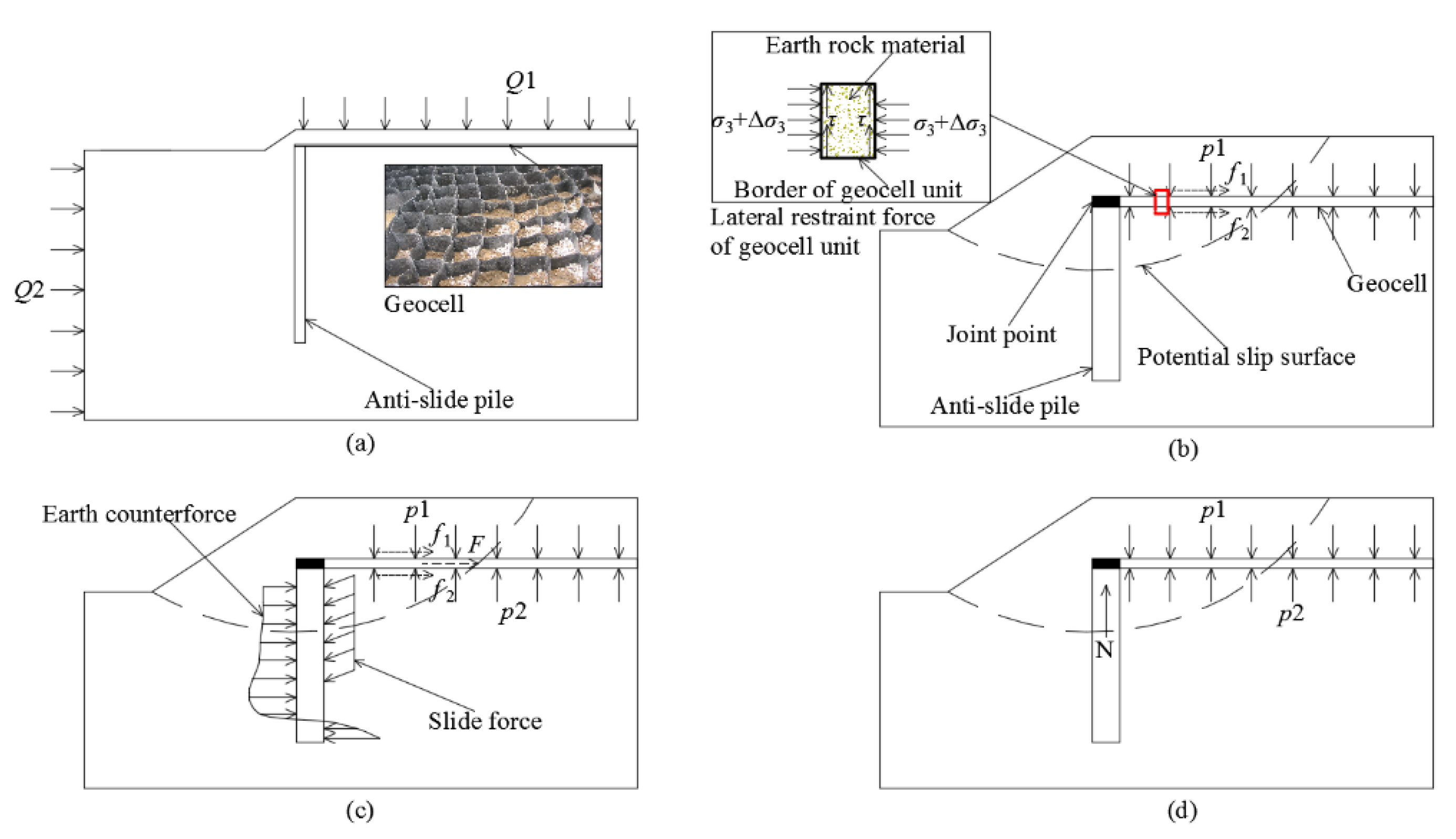
In this study, a theoretical model was first developed to investigate the working mechanism of the anti-slide pile and geocell system for riverbank slope enhancement. The loads applied on the system include the surcharge loading (Q1) of filling, etc., imposed on the top of the riverbank slope and water pressure (Q2) imposed on the left boundary of the riverbank slope. Figure 1b shows the loading condition of the geocells, which is a three-dimensional structure with excellent lateral confinement effect, horizontal friction, pull-out resistance and shear resistance [30]. The model was then validated by the field measurement data.
2.1. Theoretical Model Development
Under external loading on the riverbank slope, the increase in soil stress inside the geocells results in the outward deformation of its side walls as well as the lateral binding force and vertical friction force of the side wall of the geocell on the internal sand and aggregate, as shown in Figure 1b. Therefore, the geocells provide both the riverbank slope lateral and vertical resistance under external loads on the whole. Assuming the lateral restraint stress (Δσ3) is determined by the deformation behavior of the soil inside the geocells and the mechanical properties of the geocell material [31], and using membrane theory proposed by Henkel and Gilbertd et al. [32,33,34], Δσ3 can be expressed as
where M is the modulus of the geocell material (kN/m), d0 is the initial diameter of the geocell, εc is the allowable radial strain of the geocell, and εa is the axial strain of the geocell.
The vertical load imposed on the riverbank slope is partially carried by the anti-slide piles and the geocell layer through both confinement and beam effects. Assuming that maximum vertical friction on the geocell walls is determined by the friction angle between the geocells and soil and the lateral pressure on the wall, the maximum vertical friction stress (τ) can be expressed as
where σ3 is the total lateral pressure and φ1 is the internal friction angle of the soil, and φ2 is the internal friction angle between the geocell material and the internal soil of geocell, and Δc is the cohesion incremental.
As shown in Figure 1b,c, considering the interaction between soil and geocell, the geocell layer could provide anti-slide forces for the riverbank slope. The friction forces on the top surface (f1) and bottom surface (f2) of the geocell layer can be defined as
where c is the cohesion of the soil, p1 and p2 are the stress imposed on the top and bottom surfaces of the geocell layer, respectively, φ3 and φ4 are the internal friction angle between the material of the top and bottom surfaces of the geocell layer and the soil, respectively.
where l is the length of the geocell layer.
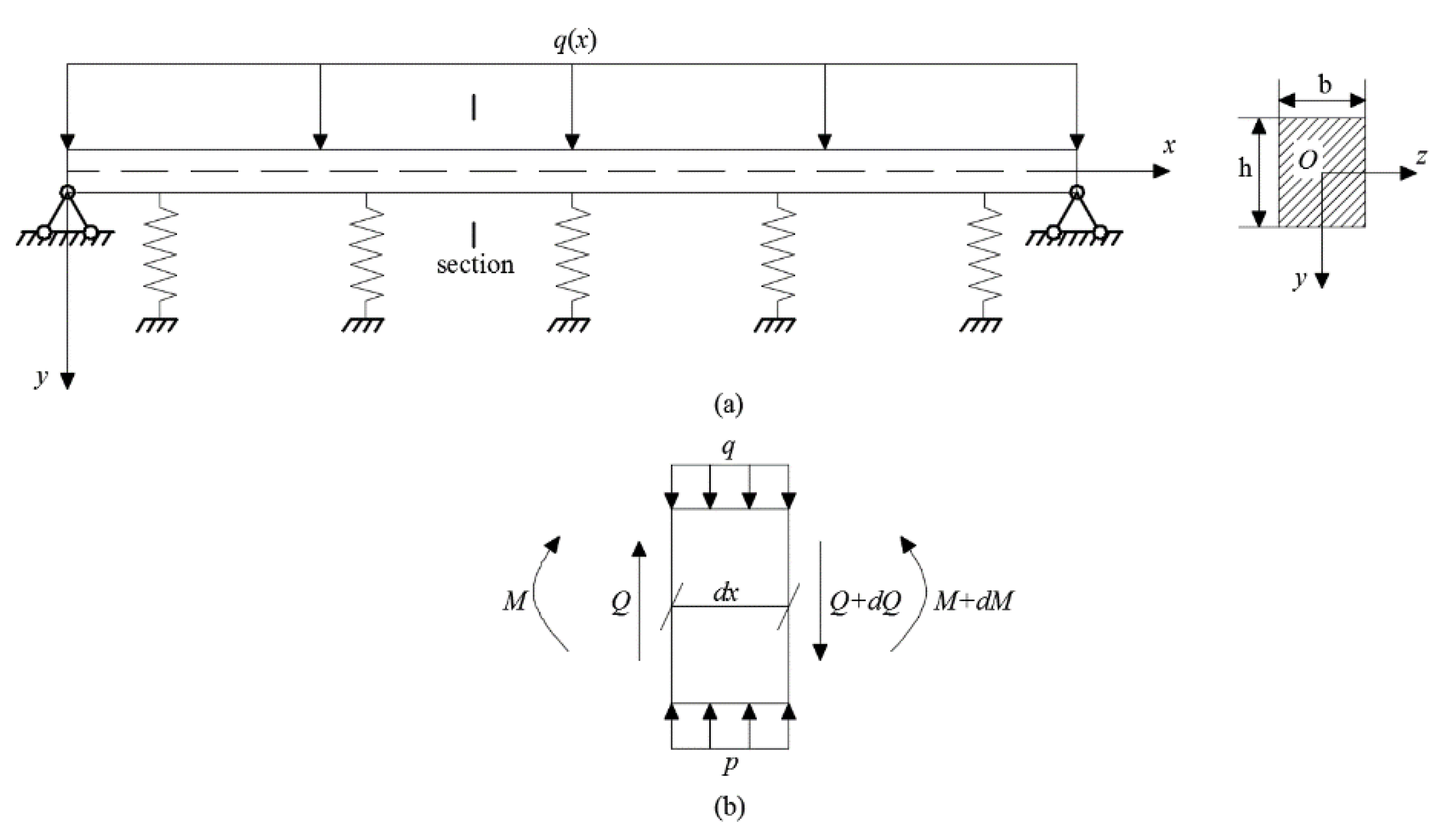
As shown in Figure 2a, the geocell layer can be modelled as a beam on elastic foundation with the loads imposed on the geocell layer, as shown in Figure 1d. The loading on a geocell beam element is shown in Figure 2b. q(x) is the surcharge loading imposed on the top of the riverbank slope Q1, which distributes the loading on the top surface of the geocell layer. p(x, y) is the reaction force on the bottom surface of the geocell layer.
The force and moment balance of the beam element lead to
where E is elastic modulus of the geocell layer and I is the moment of inertia of the geocell layer.
Furthermore, the moment of inertia of the geocell layer I can be defined as
where b is the geocell layer width and h is the geocell layer height.
2.2. Boundary Conditions
In this study, we assumed the following boundary conditions:
- The connection between the anti-slide piles and the geocell layer is rigid. The settlement of piles and rotation at the top of the piles are relatively small due to the large stiffness of the piles (i.e., at x = 0, y = 0 and θ = 0) [29].
- At the end of the geocell layer without pile support, both bending moment and shear force are zero (i.e., free end).
Assuming p(x, y) = ky where k is the elastic foundation coefficient and q(x) = q, the deflection of the geocell layer can be obtained by solving Equation (6) together with the boundary conditions, that is,
where is the eigenvalue and L = 1/β is the characteristic length.
2.3. Problem Description
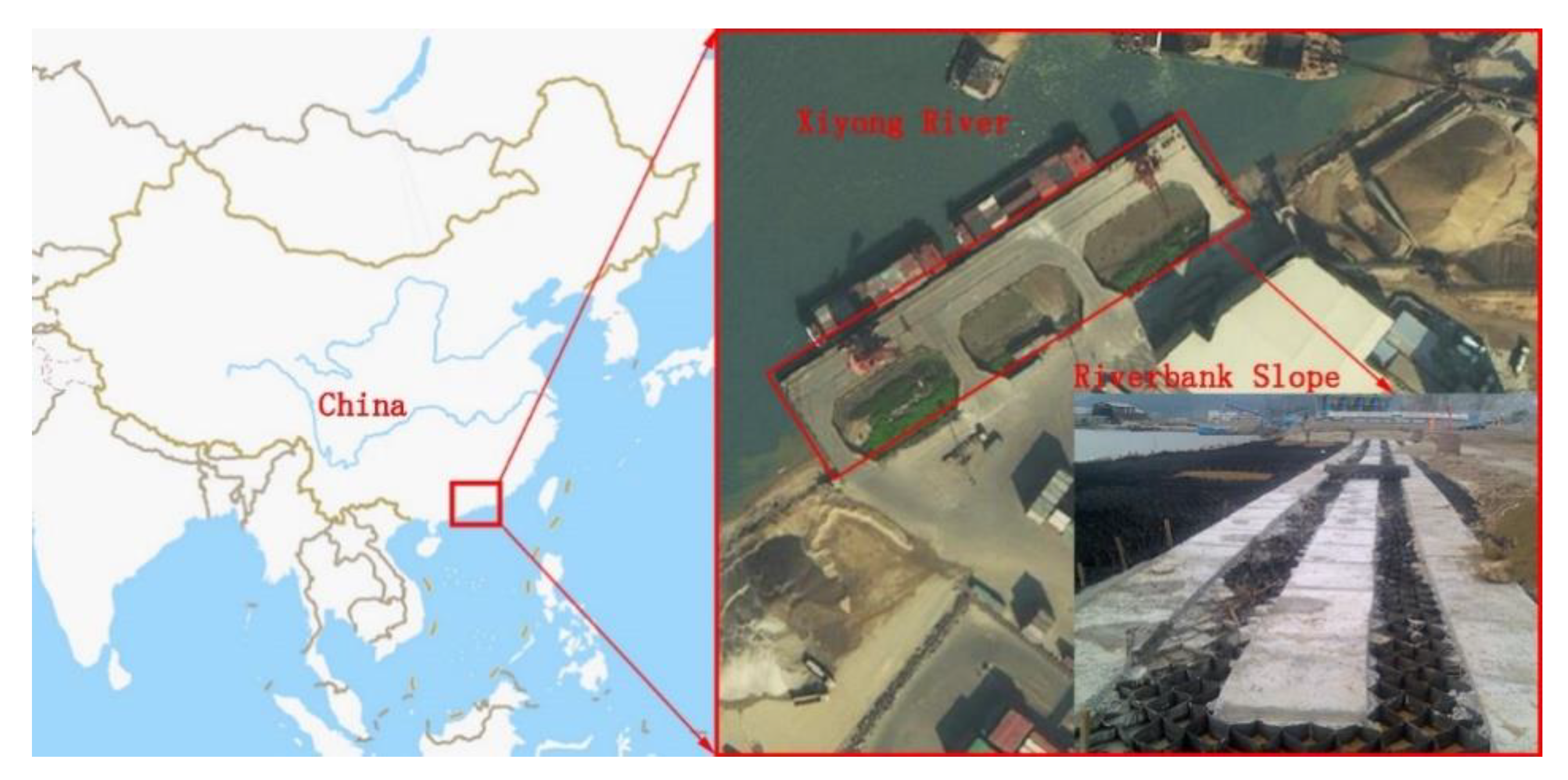
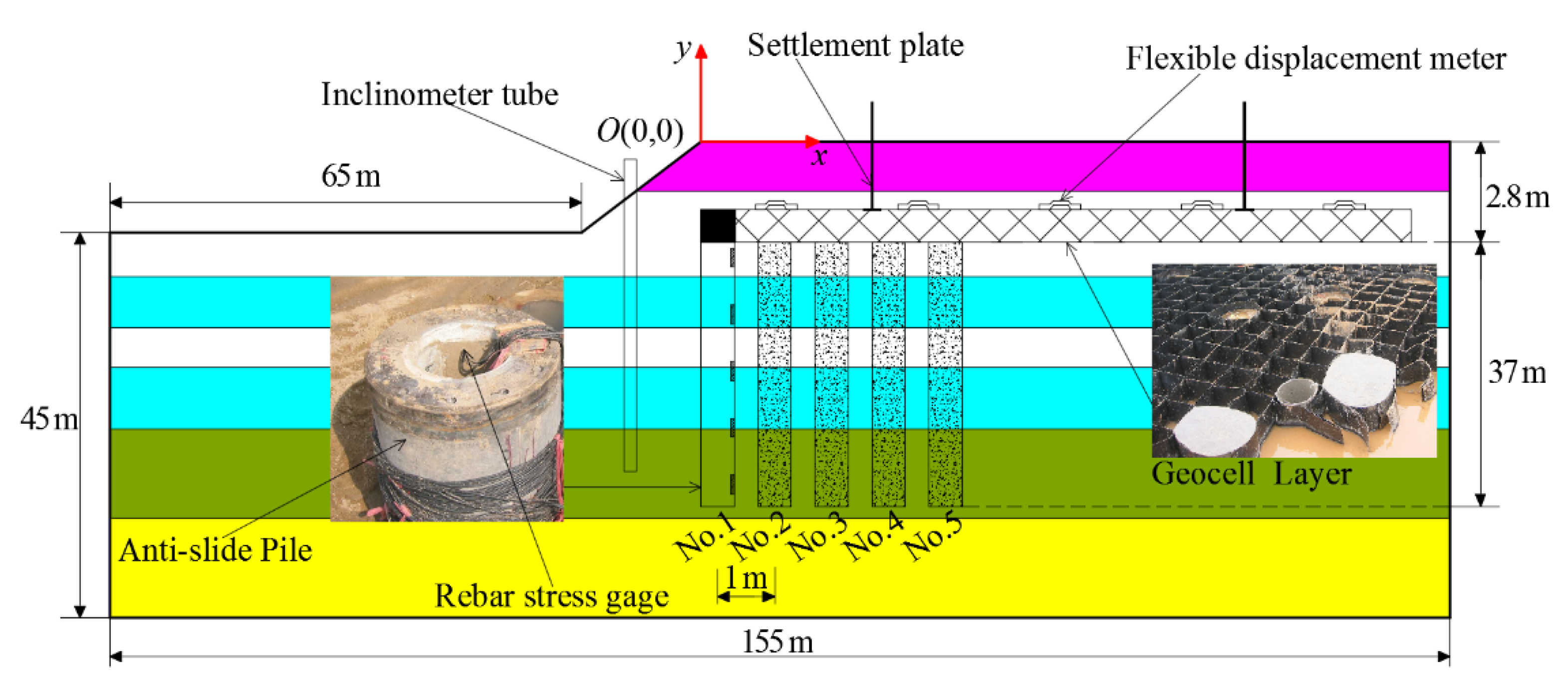
The model developed in this study was implemented to investigate a 391 m long riverbank slope in a port of the Pearl River Estuary in southern China. This riverbank slope had some small-scale landslides in the early stage of construction, as shown in Figure 3 [35]. The height of the riverbank slope is 2.8 m with a slope gradient of 1:2. Figure 4 shows the flowchart of the riverbank slope monitoring system in this study. The riverbank slope model consisted of five anti-slide piles (pre-stressed high-strength concrete, diameter of 40 cm and 37 m long each) with 1 m spacing. To investigate the influence of the anti-slide piles, 1.5 times the depth of the pile was used as the depth of the model. The height and thickness of the geocells were 100 mm and 1.2 mm, respectively, and the geocell layer was filled with sand and aggregate. Due to its weak and soft structure, the riverbank slope was enhanced by anti-slide piles and a geocell layer, with the joint point of the geocells and piles connected by concrete. While sand and aggregate were used to fill the geocell layer, sand cushion was laid under the geocell layer [36]. The details of the material properties of the riverbank slope soil, anti-slide piles and geocells are shown in Table 1. The section of material of the riverbank slope’s soil is shown in Figure 4. Furthermore, these material parameters will be used for numerical analysis.
For the proposed riverbank slope reinforcement model, this paper compares model calculations with actual measurements to verify the model’s effectiveness. Compared with the adjacent soil, the geocell structure had higher stiffness and strength, and functioned to diffuse stress and homogenize the riverbank slope deadweight. To a certain extent, the geocell structure can improve distribution of stress from the riverbank slope and anti-slide pile. In the horizontal direction, the geocells have a certain limiting effect on the lateral displacement of riverbank slope and the bending moment of the anti-slide piles. Furthermore, in the vertical direction, the main factor of variation in anti-slide pile axial force is the deadweight of the geocell layer and its upper soil, the anti-slide piles have an excellent supporting effect on the geocell layer, limiting the vertical displacement of the riverbank slope. Therefore, using model calculations, measured values of horizontal and vertical displacements of the slope, axial force end and bending moment of the anti-slide piles, the effect of a riverbank slope that is reinforced by anti-slide pile with geocell can be verified.
In order to monitor the vertical and lateral displacements of the riverbank slope more accurately, we monitored the vertical and lateral displacement of the riverbank slope a period of time after the completion of riverbank slope construction. Figure 5 shows the steps used to install monitoring sensors in the riverbank slope.
Based on the monitoring purpose and the working mechanism of the anti-slide piles and geocells, the following monitoring contents were formulated.
- Monitor the vertical and lateral displacements of the riverbank slope
For the vertical displacement of the riverbank slope, 15 displacement meters were arranged along the top of the riverbank slope, as shown in Figure 6. Furthermore, the typical resolution of the displacement meter was 0.01 mm, and the maximum vertical displacement of the riverbank slope was located on the measurement range of the displacement meter (maximum measurement range 0.8 m). One inclinometer hole with diameter 110 mm was arranged in the slide mass, and the design depth was 45 m. The inclinometer pipe was embedded in the riverbank slope in advance, and the inclinometer was used to monitor the lateral displacement of the riverbank slope.
- Monitor the axial force and bending moment of the anti-slide piles
In general, the lateral critical pile spacing of the pile group effect is about 3 times the diameter of anti-slide pile [37]. Therefore, for 40 cm diameter anti-slide pile, this paper ignores the pile group effect under the condition of 1 m distribution spacing. The bending moment is a main parameter in anti-slide piles design, and the field test is an important means for inspecting the calculated results for the bending moment. However, the bending moment is an indirect parameter—it cannot be directly observed in the field, but can be obtained by measuring the steel stress, with the rebar’s stress gage set in the longitudinal tension bar of anti-slide pile, as shown in Figure 6. According to the characteristics of the force in anti-slide piles, 22 rebar stress gages were arranged in equal distances along the longitudinal tension bar of the anti-slide pile. Furthermore, the axial force of the anti-slide piles was primarily obtained by model calculation to verify comprehensively the effect of a riverbank slope that is reinforced by anti-slide pile with geocell.
3. Results and Discussion
3.1. Finite Element (FE) Calculation
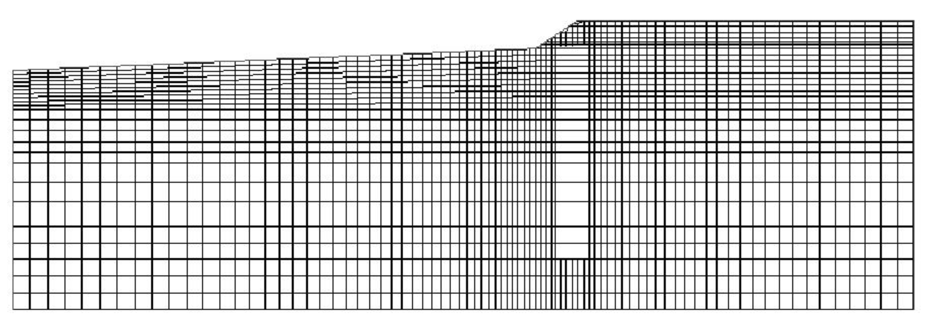
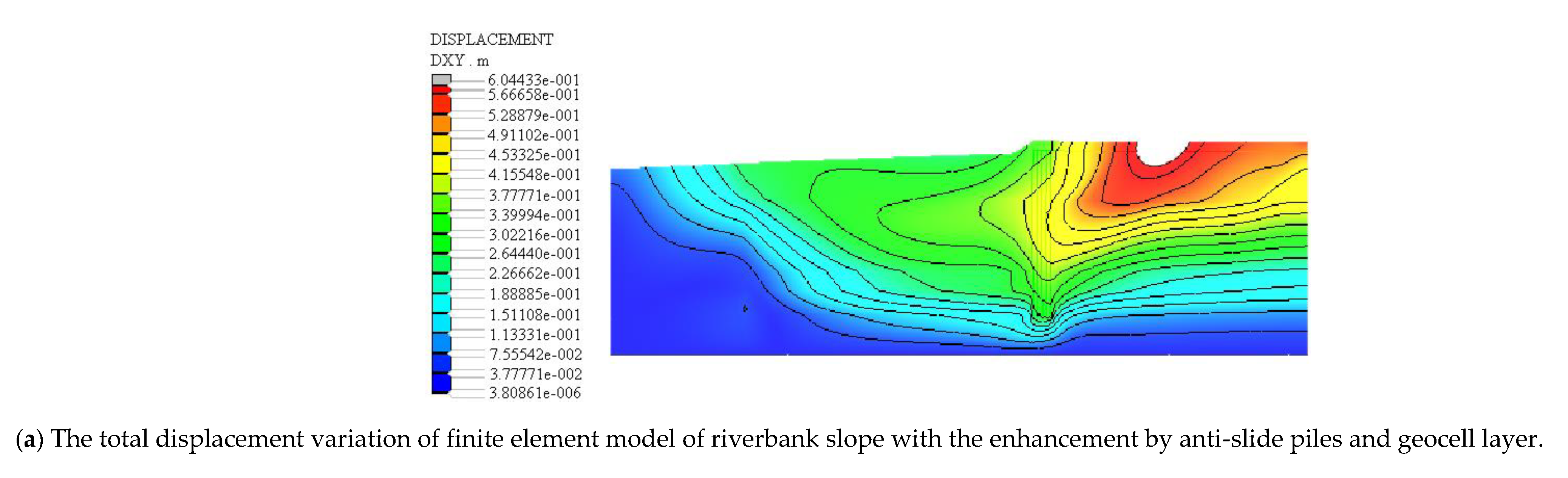
In this paper, the riverbank slope reinforced by anti-slide pile and geocell is modeled. The sand and soil are divided into eight-node quadrilateral high-order elements, and the anti-slide pile with geocell layer is divided into line beam elements. The model after meshing is shown in Figure 7; furthermore, the total displacement variation of the model of riverbank slope with and without the enhancement by anti-slide pile and geocell layer. The total displacement includes vertical settlement and lateral displacement. The calculation results are shown in Figure 8. It can be seen from Figure 8 that the total displacement of the riverbank slope is reduced after setting the enhancement by anti-slide piles and geocell layer, which proves the effectiveness of the enhancement by anti-slide piles and geocell layer.
3.2. Displacement of Riverbank Slope under Different Water Levels
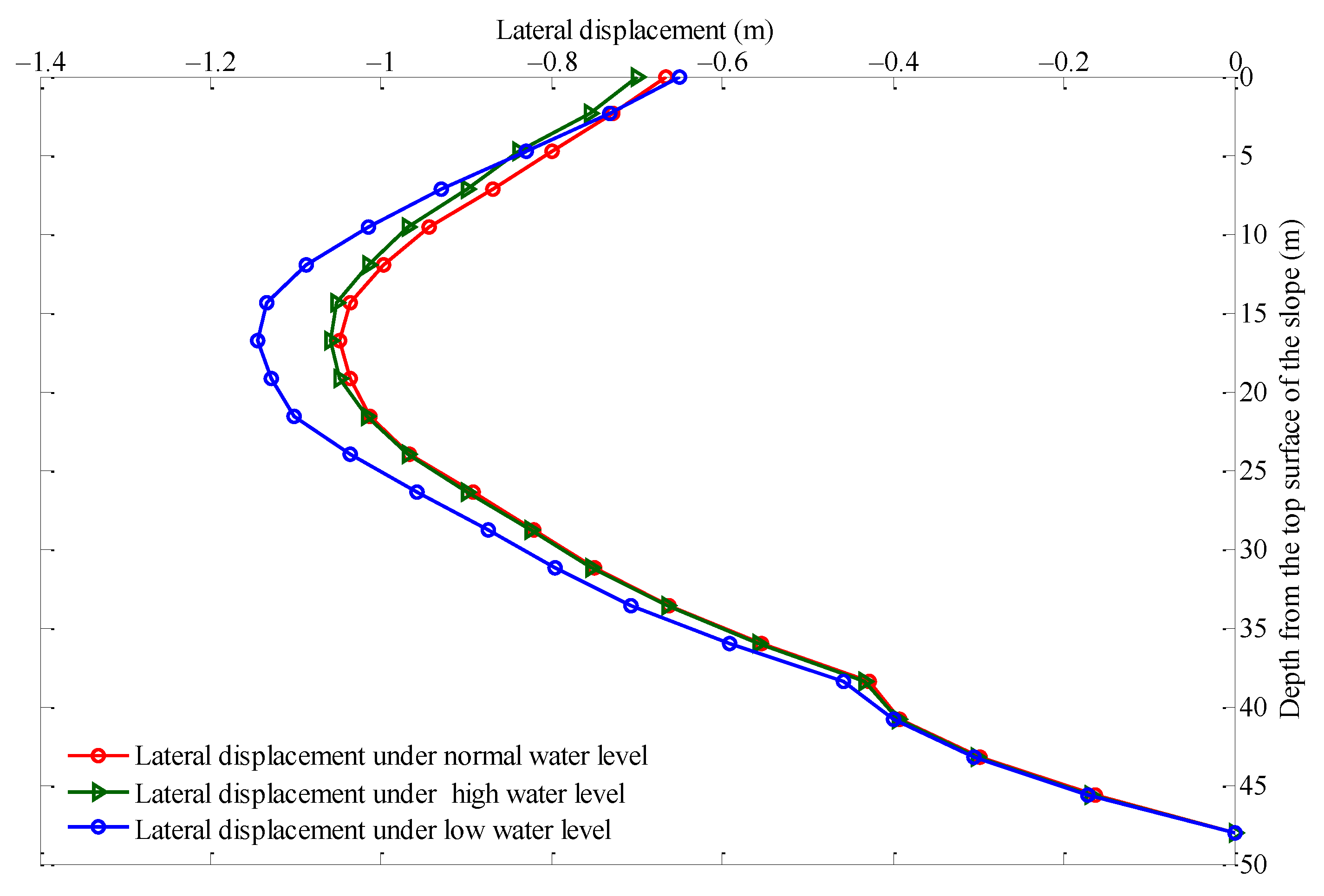
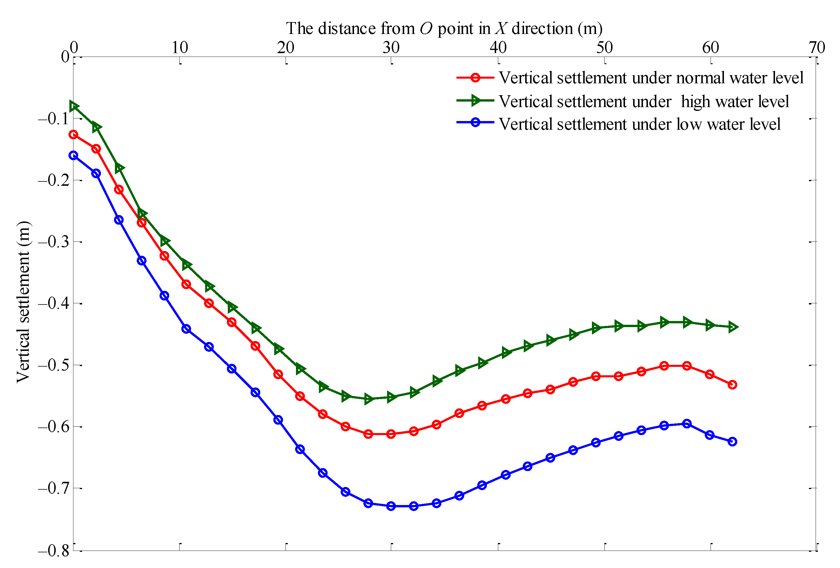
As the left side of the riverbank slope was in contact with water, the influence of water on the riverbank slope should be considered when analyzing riverbank slope stability. However, this influence is complex, and this paper provides a qualitative analysis of the influence of changes in water level through changes in vertical settlement of the top surface of the riverbank slope in the horizontal direction, and the lateral displacement under different water levels. Based on the distance between the water level and the measurement datum, the water levels of the Xiyong River can be divided into high, normal, and low water level. Further, the distance between high water level and normal water level as well as the distance between low water level and normal water level is 1 m. The change curve of the settlement value of the riverbank slope’s top surface at different water levels is shown in Figure 9, and the lateral displacement change of riverbank slope at different water levels is shown in Figure 10. Due to the elastoplastic deformation of geocell, the settlement change and lateral displacement change of riverbank slope are irreversible.
3.3. Model Validation
For the case study analysis, the left and right surface boundaries of the model were constrained horizontally while the bottom surface boundary of the model was fixed. The magnitude of the ultimate force was determined using the Mohr–Coulomb theory [38].
3.3.1. Vertical Settlement on the Top Surface of the Riverbank Slope
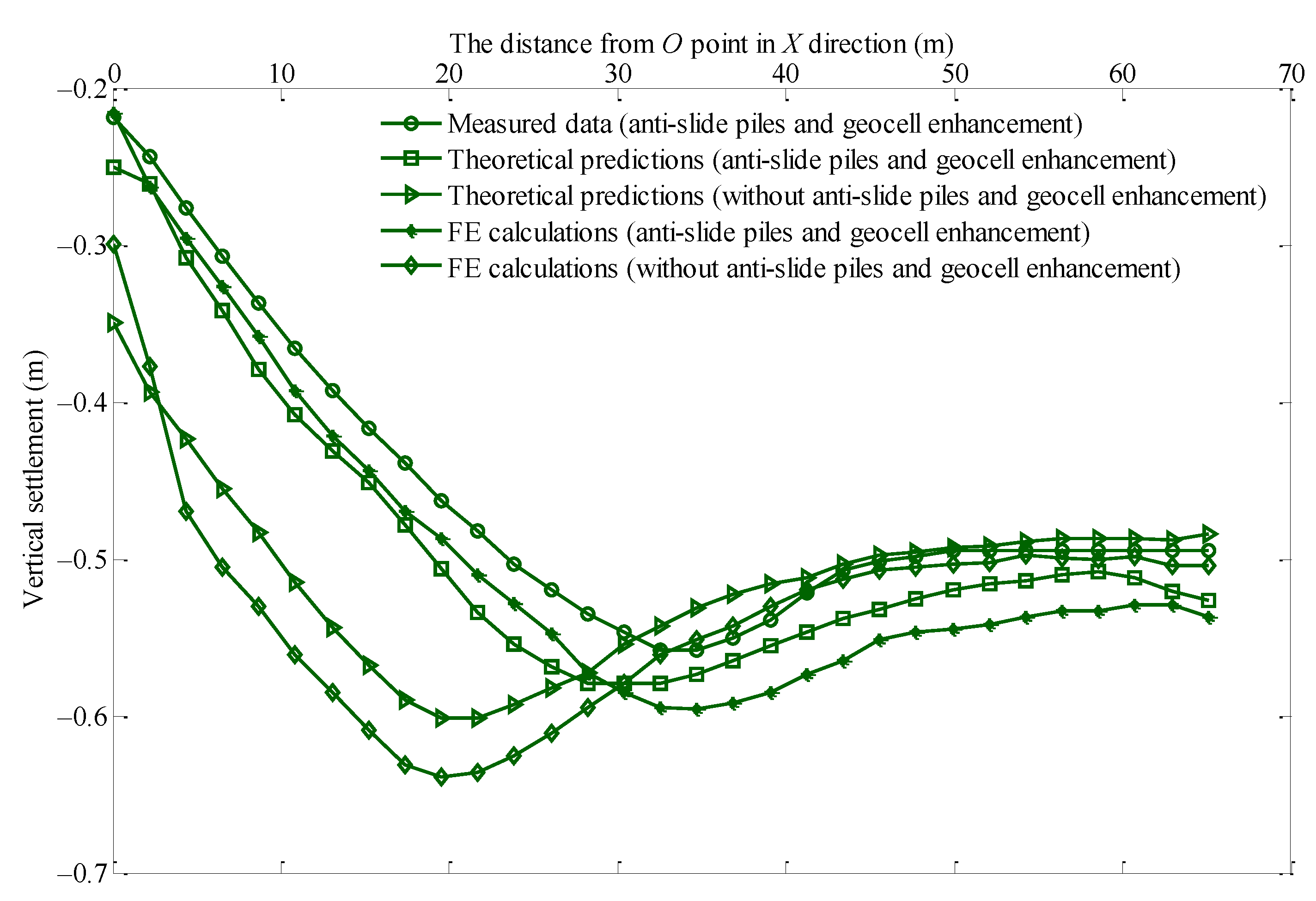
The vertical settlement on the surface of the riverbank slope was measured after riverbank slope construction had been completed for a period of time under the high water level. The measurements are presented in Figure 11, which compares the measured and predicted vertical settlement on the surface of the riverbank slope with and without riverbank slope enhancement by anti-slide piles and geocell layer. The results show that the theoretical predictions agreed with the field measurements reasonably well. The maximum vertical settlement of the riverbank slope occurred at around 30 m from the top of the riverbank slope. In addition, the figure demonstrates that the maximum vertical settlement of the riverbank slope enhanced by anti-slide piles and geocell layer could be reduced by 15% compared to that without riverbank slope enhancement, moving the maximum vertical settlement point back to around 10 m. Therefore, riverbank slope with anti-slide piles and geocell enhancement can be effectively reduced by the maximum vertical settlement.
According to the maximum value of vertical settlement of high water level, the theoretical predictions maximum value of vertical settlement without anti-slide piles and geocell enhancement is compared with the actual measured maximum value of the vertical settlement. It was found that the percentage of influence of high water level on the vertical settlement of riverbank slope in the above two situation reaches 11% without anti-slide piles and geocell enhancement and 5% with anti-slide piles and geocell enhancement, respectively. Therefore, the riverbank slope with anti-slide piles and geocell enhancement can be effectively reduced by the influence of water level.
3.3.2. Depth-Dependent Lateral Displacement of the Riverbank Slope
Figure 12 compares the measured and predicted depth-dependent lateral settlement of the riverbank slope, with and without the riverbank slope enhancement by anti-slide piles and geocell layer. It shows that the theoretical predictions fit the field measurements well. In addition, it indicates that the lateral displacement of the riverbank slope initially increased with depth, reached maximum value (around 0.45 m) at around 17 m, and then gradually decreased. Most importantly, the theoretical results demonstrate that the anti-slide piles and geocell layer could decrease the maximum lateral displacement by around 40%.
3.4. Mechanical Behavior of the Anti-Slide Piles
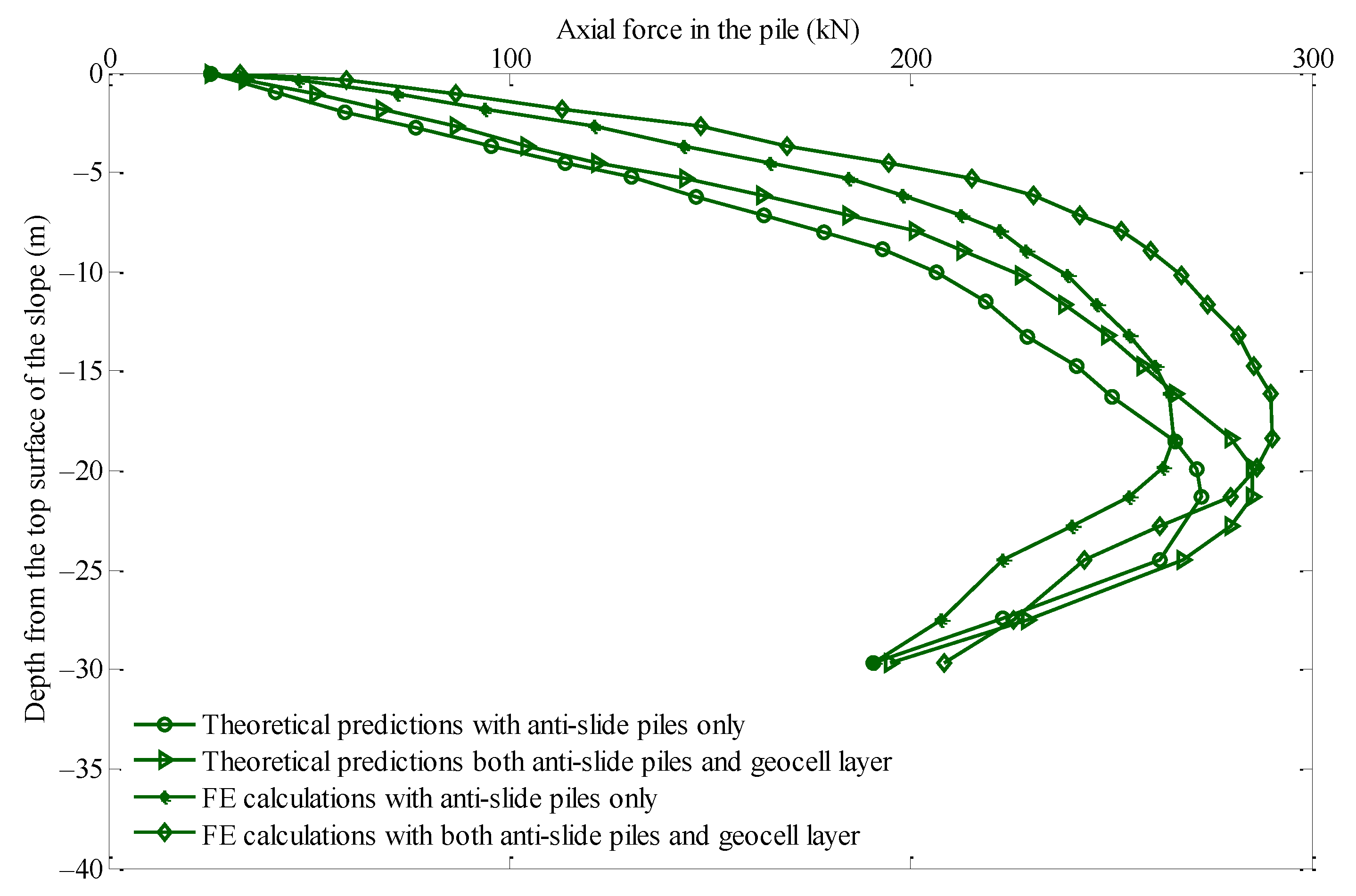
Due to the above analysis results, the model was implemented to investigate the mechanical behavior of the anti-slide piles in the riverbank slope. Figure 13 compares the depth-dependent axial force of the No. 1 anti-slide pile, with and without geocell layer. Among them, the results of FE calculation are similar with theoretical prediction. It shows that the axial force in this pile initially increased with increase in depth, reached maximum value at a depth of around 23 m, and then gradually decreased. In addition, although the application of the geocell layer could increase the axial force in the anti-slide piles, the increase in maximum axial force was limited (around 7%).
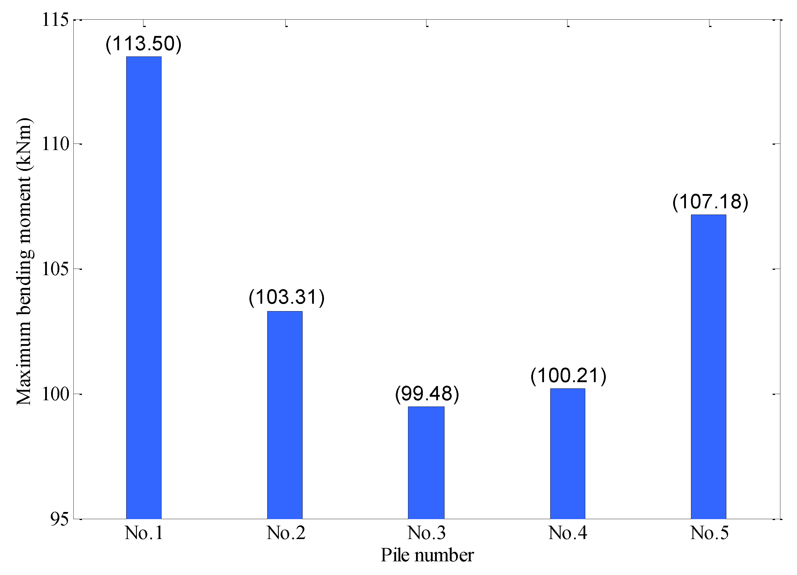
In addition to axial force, the anti-slide piles were also subject to bending moment, which can be calculated using the interaction model of anti-slide pile and soil. Figure 14 shows that the anti-slide piles located at riverbank slope boundaries were subject to a relatively large bending moment. Geocell layer and anti-slide piles are jointly composed of a slope side pressure support system. The outermost No. 1 anti-slide pile is near the free face above the water surface, which bears the force of the soil behind the riverbank slope, anti-slide piles and geocell layer. Therefore, the bending moment of the No. 1 anti-slide pile is relatively large. Furthermore, the No. 5 anti-slide pile is subjected firstly to the force of the soil behind the riverbank slope, so the bending moment is also relatively large. The No. 2 anti-slide pile, No. 3 anti-slide pile and No. 4 anti-slide pile are located in the middle part of the pile group, and undertake the force of the soil behind the riverbank slope and the geocell layer jointly. Therefore, the bending moment of the No. 2 anti-slide pile, No. 3 anti-slide pile and No. 4 anti-slide pile is relatively small.
4. Conclusions
In the present study, a theoretical model was proposed to investigate the effects of riverbank slope enhanced by anti-slide piles and geocell layer. The model was validated using field measurement data. The following are the major findings.
The theoretical predictions fit the field measurements reasonably well. The model predicted that the maximum vertical settlement position of the top surface of the riverbank slope would be around 30 m from the edge of the top of the riverbank slope, and the use of the anti-slide piles and geocell layer would reduce vertical settlement by 15% and move the maximum vertical settlement point back by around 10 m.
The lateral displacement of the riverbank slope initially increased with depth, reached its maximum value (around 0.45 m) at around 17 m, and then gradually decreased. The use of the anti-slide piles and geocell layer was measured to decrease maximum lateral displacement by around 40%.
The axial force in the pile initially increased with increase in depth, reached its maximum value at a depth of around 23 m, and then gradually decreased. The application of the geocell layer was found to increase axial force in the anti-slide piles to some extent.
Author Contributions
Conceptualization, C.Z. and Z.L.; methodology, C.Z. and Z.L.; software, Z.L. and P.L.; validation, C.Z., Z.L., P.L.; formal analysis, Z.L., P.L.; investigation, Z.L., P.L.; resources, C.Z. and Z.L.; data curation, Z.L. and P.L.; writing—original draft preparation, Z.L. and P.L.; writing—review and editing, C.Z., Z.L., P.L., Y.L., L.Z.; visualization, Z.L. and P.L.; supervision, C.Z. and Z.L.; project administration, C.Z. and Z.L.; funding acquisition, C.Z. and Z.L. All authors have read and agreed to the published version of the manuscript.
Funding
This research was funded by the Ministry of Science and Technology of The People´s Republic of China, grant numbers 2017YFC1501203 and 2017YFC1501201; National Natural Science Foundation of China, grant numbers 41530638 and 41977230; and Guangdong Science and Technology Department, grant numbers 2015B090925016 and 2016B010124007.
Institutional Review Board Statement
Not applicable.
Informed Consent Statement
Not applicable.
Data Availability Statement
The data are presented in the paper.
Acknowledgments
The authors are greatly thankful to the assistant editor for consultation, to the Journalof Marine Science and Engineering Editorial Office for editing and reviewing the manuscript and to the experts of external audit for proposing valuable suggestions for this paper.
Conflicts of Interest
The authors declare no conflict of interest.
References
- Hegde, A.; Sitharam, T. Three-dimensional numerical analysis of geocell-reinforced soft clay beds by considering the actual geometry of geocell pockets. Can. Geotech. J. 2015, 52, 1396–1407. [Google Scholar] [CrossRef]
- Mastbergen, D.R.; Beinssen, K.; Nédélec, Y. Watching the Beach Steadily Disappearing: The Evolution of Understanding of Retrogressive Breach Failures. J. Mar. Sci. Eng. 2019, 7, 368. [Google Scholar] [CrossRef] [Green Version]
- Stacul, S.; Squeglia, N.; Morelli, F. Laterally loaded single pile response considering the influence of suction and non-linear behaviour of reinforced concrete sections. Appl. Sci. 2017, 7, 1310. [Google Scholar] [CrossRef] [Green Version]
- Duncan, J.M.; Evans, L.T., Jr.; Ooi, P.S. Lateral load analysis of single piles and drilled shafts. J. Geotech. Eng. 1994, 120, 1018–1033. [Google Scholar] [CrossRef]
- Zhang, Z.; Wei, H.; Qin, X. Experimental study on damping characteristics of soil-structure interaction system based on shaking table test. Soil Dyn. Earthq. Eng. 2017, 98, 183–190. [Google Scholar] [CrossRef]
- Kavitha, P.; Beena, K.; Narayanan, K. A review on soil-structure interaction analysis of laterally loaded piles. Innov. Infrastruct. Solut. 2016, 1, 1–15. [Google Scholar] [CrossRef] [Green Version]
- Chore, H.; Ingle, R.; Sawant, V. Parametric study of laterally loaded pile groups using simplified FE models. Coupled Syst. Mech. 2012, 1, 1–18. [Google Scholar] [CrossRef]
- Mostofi, A.; Bargi, K. Analytical and numerical evaluation of flexible response of floating piers to ship berthing impact. Int. J. Civ. Struct. Eng. 2011, 2, 249. [Google Scholar]
- Küçükarslan, S.; Banerjee, P.; Bildik, N. Inelastic analysis of pile soil structure interaction. Eng. Struct. 2003, 25, 1231–1239. [Google Scholar] [CrossRef]
- Dutta, S.; Mandal, J. Model studies on encased fly ash column–geocell composite systems in soft clay. J. Hazard Toxic Radioact. Waste 2017, 21, 04017001. [Google Scholar] [CrossRef]
- Han, J.; Gabr, M. Numerical analysis of geosynthetic-reinforced and pile-supported earth platforms over soft soil. J. Geotech. Geoenviron. Eng. 2002, 128, 44–53. [Google Scholar] [CrossRef]
- Hegde, A. Geocell reinforced foundation beds-past findings, present trends and future prospects: A state-of-the-art review. Constr. Build. Mater. 2017, 154, 658–674. [Google Scholar] [CrossRef]
- Latha, G.M.; Dash, S.K.; Rajagopal, K. Numerical simulation of the behavior of geocell reinforced sand in foundations. Int. J. Geomech. 2009, 9, 143–152. [Google Scholar] [CrossRef]
- Zheng, J.; Chen, B.; Lu, Y.; Abusharar, S.; Yin, J. The performance of an embankment on soft ground reinforced with geosynthetics and pile walls. Geosynth. Int. 2009, 16, 173–182. [Google Scholar] [CrossRef]
- Pokharel, S.K. Experimental Study on Geocell-Reinforced Bases under Static and Dynamic Loading; University of Kansas: Lawrence, KS, USA, 2010. [Google Scholar]
- Song, F.; Tian, Y. Three-dimensional numerical modelling of geocell reinforced soils and its practical application. Geomech. Eng. 2019, 17, 1–9. [Google Scholar]
- Mehdipour, I.; Ghazavi, M.; Ziaie Moayed, R. Stability analysis of geocell-reinforced slopes using the limit equilibrium horizontal slice method. Int. J. Geomech. 2017, 17, 06017007. [Google Scholar] [CrossRef]
- Hegde, A.; Sitharam, T. 3-Dimensional numerical modelling of geocell reinforced sand beds. Geotext. Geomembr. 2015, 43, 171–181. [Google Scholar] [CrossRef]
- Liu, Y.; Deng, A.; Jaksa, M. Three-dimensional discrete-element modeling of geocell-reinforced ballast considering breakage. Int. J. Geomech. 2020, 20, 04020032. [Google Scholar] [CrossRef]
- Dash, S.K.; Krishnaswamy, N.R.; Rajagopal, K. Bearing capacity of strip footings supported on geocell-reinforced sand. Geotext. Geomembr. 2001, 19, 235–256. [Google Scholar] [CrossRef]
- Biswas, A.; Krishna, A.M. Geocell-reinforced foundation systems: A critical review. Int. J. Geosynth Ground. Eng. 2017, 3, 17. [Google Scholar] [CrossRef]
- Halder, K.; Chakraborty, D. Influence of soil spatial variability on the response of strip footing on geocell-reinforced slope. Comput. Geotech. 2020, 122, 103533. [Google Scholar] [CrossRef]
- Dash, S.K.; Shivadas, A.S. Performance improvement of railway ballast using geocells. Indian Geotech. J. 2012, 42, 186–193. [Google Scholar] [CrossRef]
- Lambert, S.; Gotteland, P.; Nicot, F. Experimental study of the impact response of geocells as components of rockfall protection embankments. Nat. Hazards Earth Syst. Sci. 2009, 9, 459–467. [Google Scholar] [CrossRef]
- Sheikh, I.R.; Shah, M. Experimental study on geocell reinforced base over dredged soil using static plate load test. Int. J. Pavement Res. Technol. 2020, 13, 286–295. [Google Scholar] [CrossRef]
- Siabil, S.G.; Tafreshi, S.M.; Dawson, A. Response of pavement foundations incorporating both geocells and expanded polystyrene (EPS) geofoam. Geotext. Geomembr. 2020, 48, 1–23. [Google Scholar] [CrossRef]
- Emersleben, A.; Meyer, N. Use of Geocell Reinforced Load Transfer Platforms over Vertical Columns. In Geo-Frontiers 2011: Advances in Geotechnical Engineering; ASCE: Reston, VA, USA, 2011; pp. 3255–3265. [Google Scholar]
- Tafreshi, S.M.; Javadi, S.; Dawson, A. Influence of geocell reinforcement on uplift response of belled piles. Acta Geotech. 2014, 9, 513–528. [Google Scholar] [CrossRef] [Green Version]
- Zhao, M.; Zhang, L.; Zou, X.; Zhao, H. Research progress in two-direction reinforced composite foundation formed by geocell reinforced mattress and gravel piles. Chin. J. Highway Transp. 2009, 22, 1–10. [Google Scholar]
- Avesani Neto, J.; Bueno, B.; Futai, M. Evaluation of a calculation method for embankments reinforced with geocells over soft soils using finite-element analysis. Geosynth. Int. 2015, 22, 439–451. [Google Scholar] [CrossRef]
- Kumar, S.; Sahu, A.K.; Naval, S. Performance of circular footing on expansive soil bed reinforced with geocells of Chevron pattern. Civ. Eng. J. 2019, 5, 2333–2348. [Google Scholar] [CrossRef]
- Zhang, L.; Gardiner, B.S.; Smith, D.W.; Pivonka, P.; Grodzinsky, A.J. IGF uptake with competitive binding in articular cartilage. J. Biol. Syst. 2008, 16, 175–195. [Google Scholar] [CrossRef] [Green Version]
- Zhang, L.; Smith, D.W.; Gardiner, B.S.; Grodzinsky, A.J. Modeling the Insulin-Like Growth Factor System in Articular Cartilage. PLoS ONE 2013, 8, e66870. [Google Scholar] [CrossRef] [Green Version]
- Bathurst, R.J.; Karpurapu, R. Large-scale triaxial compression testing of geocell-reinforced granular soils. Geotech. Test. J. 1993, 16, 296–303. [Google Scholar]
- Zhuhai Hongwan Port Phase I Project, 2005. Available online: https://map.baidu.com/@12631011,2515555.75,18z/maptype%3DB_SATELLITE_MAP (accessed on 1 March 2021).
- Zhang, L.; Zhao, M.; Shi, C. Bearing capacity of geocell reinforcement in embankment engineering. Geotext. Geomembr. 2010, 28, 475–482. [Google Scholar] [CrossRef]
- Kourkoulis, R.; Gelagoti, F.; Anastasopoulos, I. Slope stabilizing piles and pile-groups: Parametric study and design insights. J. Geotech. Geoenviron. Eng. 2011, 137, 663–677. [Google Scholar] [CrossRef] [Green Version]
- Madhavi Latha, G.; Rajagopal, K.; Krishnaswamy, N. Experimental and theoretical investigations on geocell-supported embankments. Int. J. Geomech. 2006, 6, 30–35. [Google Scholar] [CrossRef]
Figure 1.
The proposed theoretical model for investigating an anti-slide pile and geocell system for riverbank slope enhancement. (a) Detailed design of anti-slide pile with geocells (Q1: Surcharge loading imposed on top of the riverbank slope; Q2: Water pressure imposed on the left boundary of the riverbank slope); (b) Loading condition of the geocell layer; (c) Loading condition of the anti-slide pile; and (d) Load transfer between the anti-slide pile and geocell.

Figure 2.
(a) Modelling the geocell layer as a beam on elastic foundation; (b) A geocell beam element.
Figure 2.
(a) Modelling the geocell layer as a beam on elastic foundation; (b) A geocell beam element.

Figure 3.
Location of the riverbank slope for the model developed in this study.

Figure 4.
The section of material of the riverbank slope’s soil.

Figure 5.
The steps used to install monitoring sensors in the riverbank slope: (a) sensor calibration; (b) geocell and anti-slide pile layout; (c) grouting and sealing; (d) filling.
Figure 5.
The steps used to install monitoring sensors in the riverbank slope: (a) sensor calibration; (b) geocell and anti-slide pile layout; (c) grouting and sealing; (d) filling.

Figure 6.
A schematic diagram showing the sectional details of monitoring of the riverbank slope model in this study; point O is the origin of values of model calculation and actual measurement (155 m wide, 65 m from the riverbank slope toe to the left boundary of the riverbank slope, and 90 m from the riverbank slope toe to the right boundary of the riverbank slope).

Figure 7.
Computational model after meshing.

Figure 8.
The finite element analysis result.


Figure 9.
The depth-dependent lateral displacement of the riverbank slope under different water levels.
Figure 9.
The depth-dependent lateral displacement of the riverbank slope under different water levels.

Figure 10.
Vertical settlement of the top surface of the riverbank slope in the horizontal direction under different water levels.
Figure 10.
Vertical settlement of the top surface of the riverbank slope in the horizontal direction under different water levels.

Figure 11.
Vertical settlement of the top surface of the riverbank slope in the horizontal direction.
Figure 11.
Vertical settlement of the top surface of the riverbank slope in the horizontal direction.

Figure 12.
Depth-dependent lateral displacement of the riverbank slope.

Figure 13.
Depth-dependent axial force in the No. 1 anti-slide pile.

Figure 14.
Maximum bending moment of individual anti-slide piles.


Table 1.
The material properties of the riverbank slope’s soil, anti-slide piles and geocells.
| Soil Layer Name | Thickness (m) | Deformation Modulus (MPa) | Poisson’s Ratio ν | Severe γ (kN/m3) | Cohesion c (kPa) | Internal Friction Angle φ (°) |
|---|---|---|---|---|---|---|
| Original artificial fill | 10.4 | 14 | 0.2 | 19.5 | 10 | 12 |
| Silt | 9.3 | 1.5 | 0.42 | 16.5 | 5 | 2 |
| Mucky soil | 6.7 | 1.8 | 0.4 | 17 | 10 | 3.5 |
| Clay | 4.3 | 4.5 | 0.35 | 19.5 | 30 | 9 |
| Silt clay | 5.5 | 1.8 | 0.4 | 17 | 10 | 3.5 |
| Clay | 8.8 | 4.5 | 0.35 | 19.5 | 22 | 9 |
| New artificial fill | 3.8 | 14 | 0.2 | 18 | 10 | 12 |
| Sand | 0.5 | 15 | 0.25 | 20 | 1 | 25 |
| Anti-slide pile | 37.0 | 30,000 | 0.2 | 25 | —— | —— |
| Geocell | 0.2 | 40 | 0.2 | 20 | —— | —— |
Publisher’s Note: MDPI stays neutral with regard to jurisdictional claims in published maps and institutional affiliations. |
© 2021 by the authors. Licensee MDPI, Basel, Switzerland. This article is an open access article distributed under the terms and conditions of the Creative Commons Attribution (CC BY) license (https://creativecommons.org/licenses/by/4.0/).
Share and Cite
MDPI and ACS Style
Liu, Z.; Liu, P.; Zhou, C.; Li, Y.; Zhang, L. Modeling Riverbank Slope Reinforcement Using Anti-Slide Piles with Geocells. J. Mar. Sci. Eng. 2021, 9, 394. https://doi.org/10.3390/jmse9040394
AMA Style
Liu Z, Liu P, Zhou C, Li Y, Zhang L. Modeling Riverbank Slope Reinforcement Using Anti-Slide Piles with Geocells. Journal of Marine Science and Engineering. 2021; 9(4):394. https://doi.org/10.3390/jmse9040394
Chicago/Turabian StyleLiu, Zhen, Pengzhen Liu, Cuiying Zhou, Yasheng Li, and Lihai Zhang. 2021. "Modeling Riverbank Slope Reinforcement Using Anti-Slide Piles with Geocells" Journal of Marine Science and Engineering 9, no. 4: 394. https://doi.org/10.3390/jmse9040394
Note that from the first issue of 2016, this journal uses article numbers instead of page numbers. See further details here.