
Laser Powder Bed Fusion of a Topology Optimized and Surface Textured Rudder Bulb with Lightweight and Drag-Reducing Design


 ,
,
Abstract
:1. Introduction
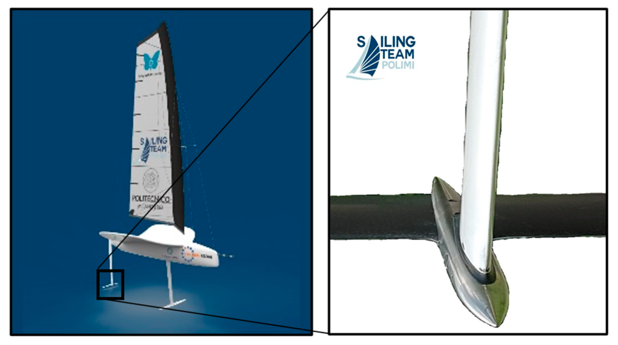
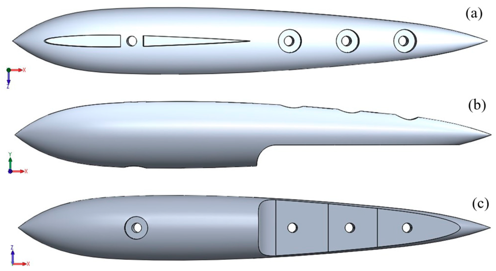
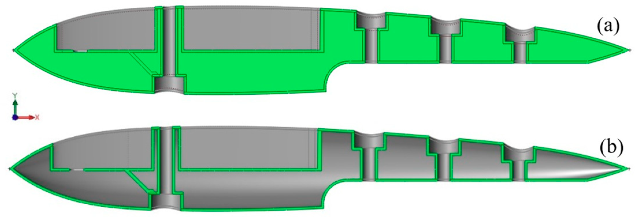
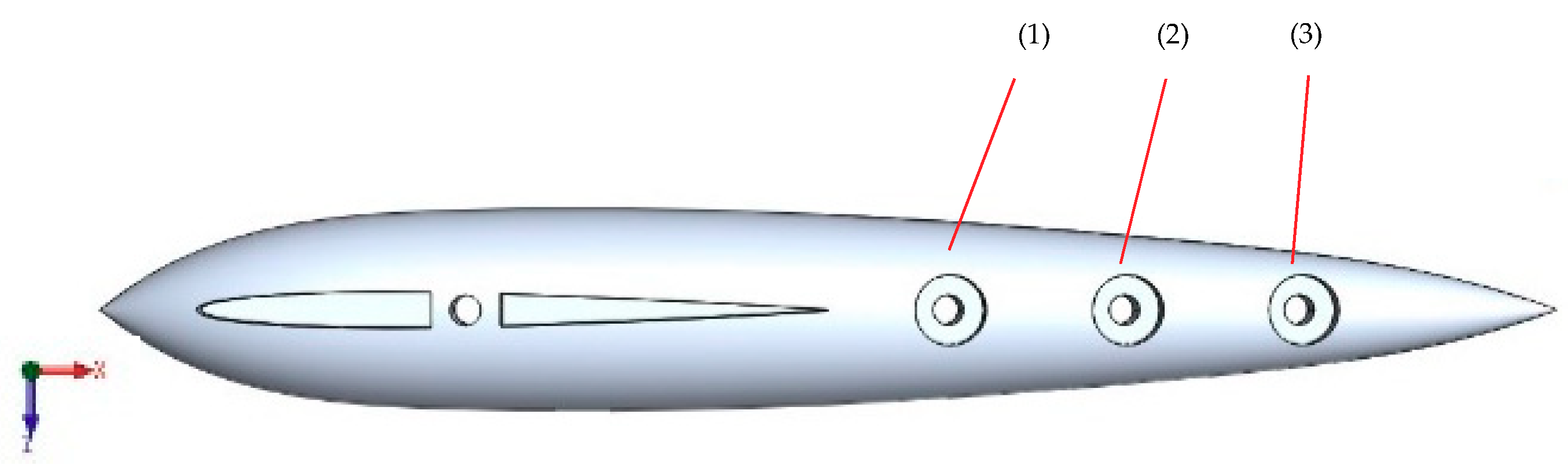
2. Design of the Rudder Bulb
2.1. Design Requirements and Choices
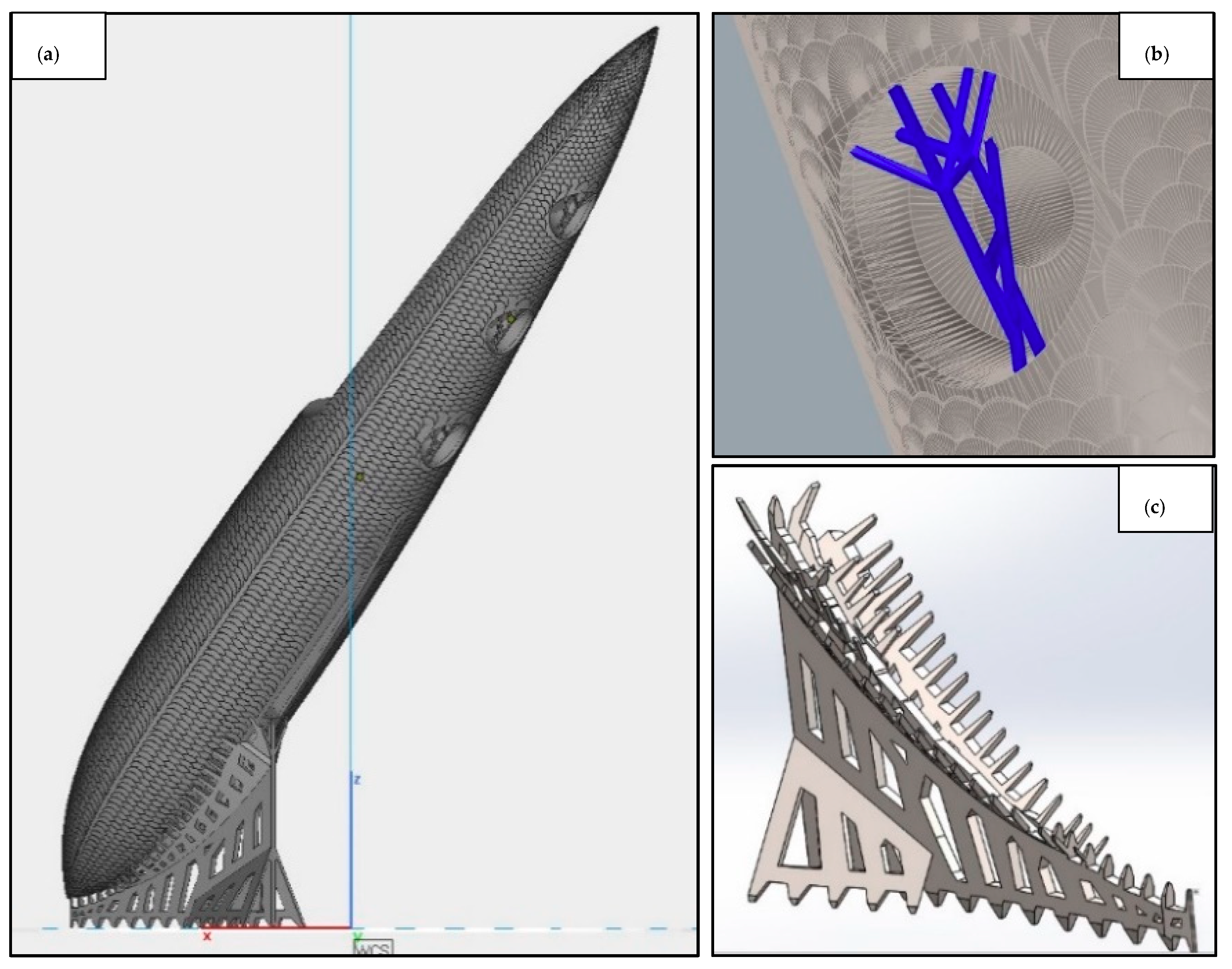
2.2. Topology Optimization Strategy
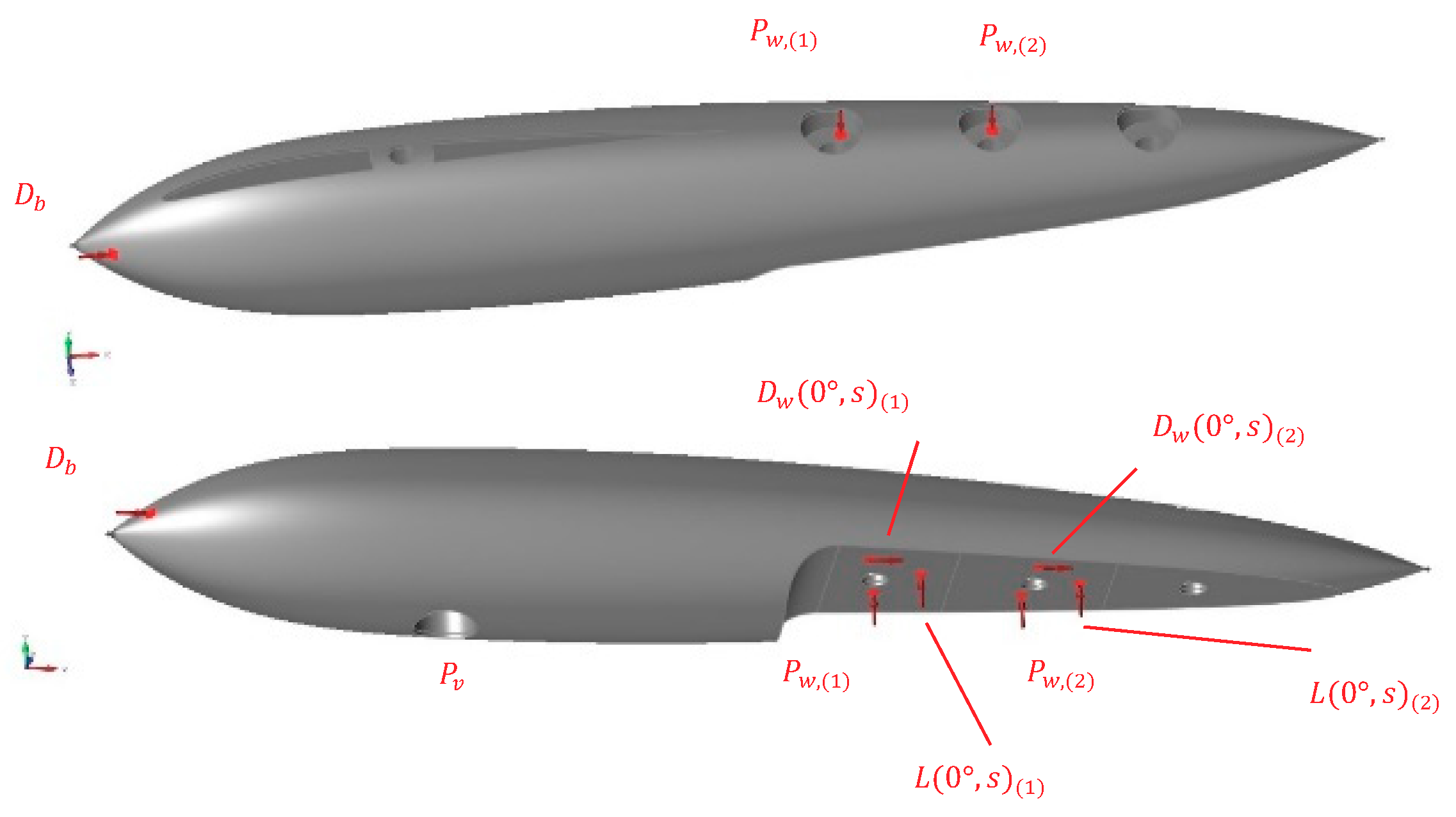
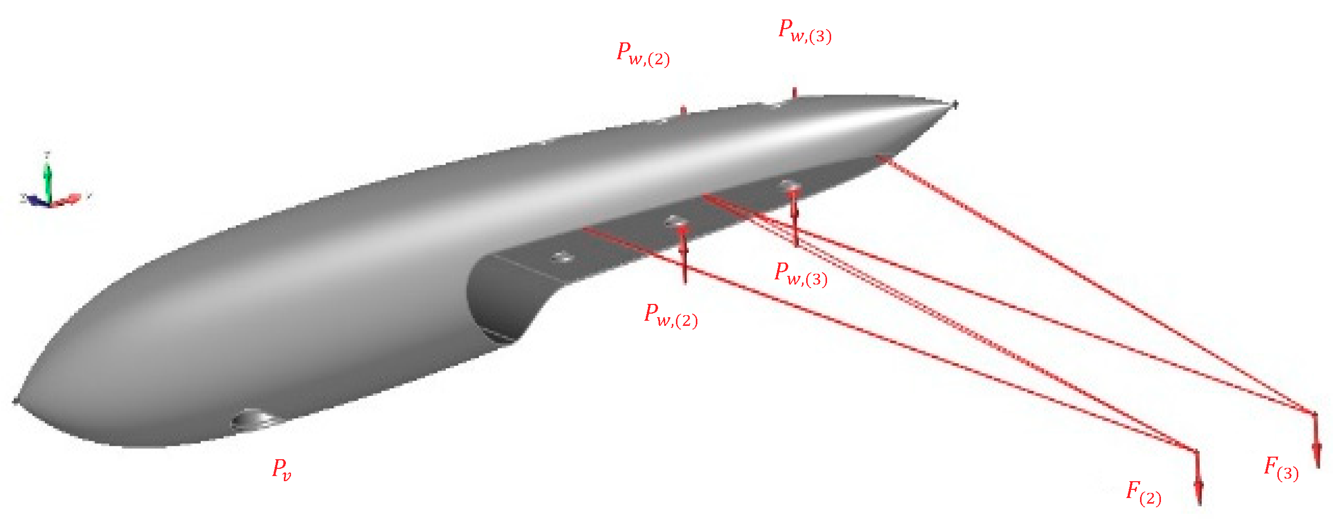
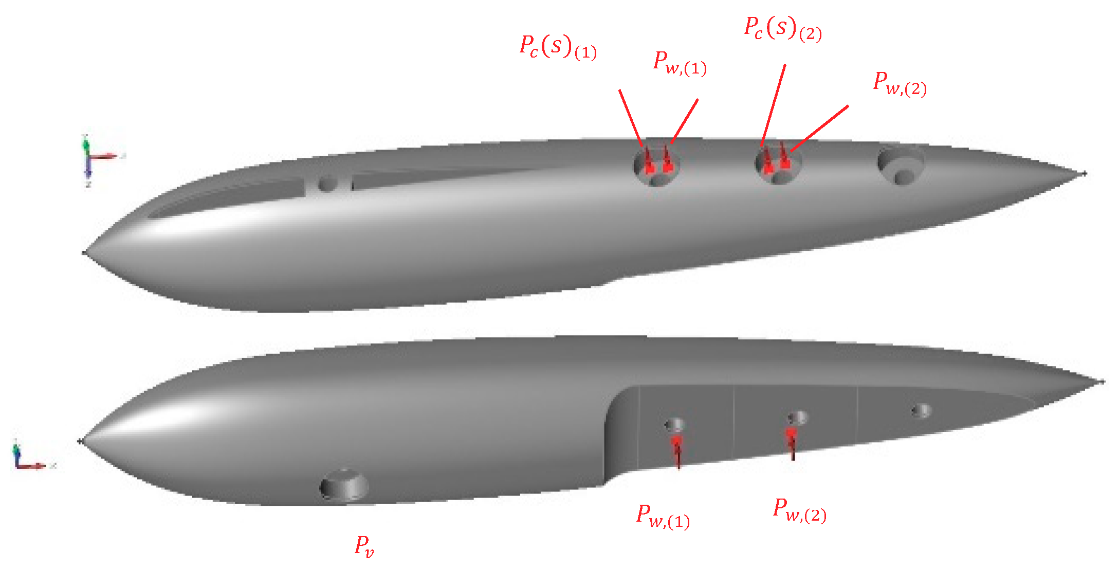
2.3. Definition of the Load Cases
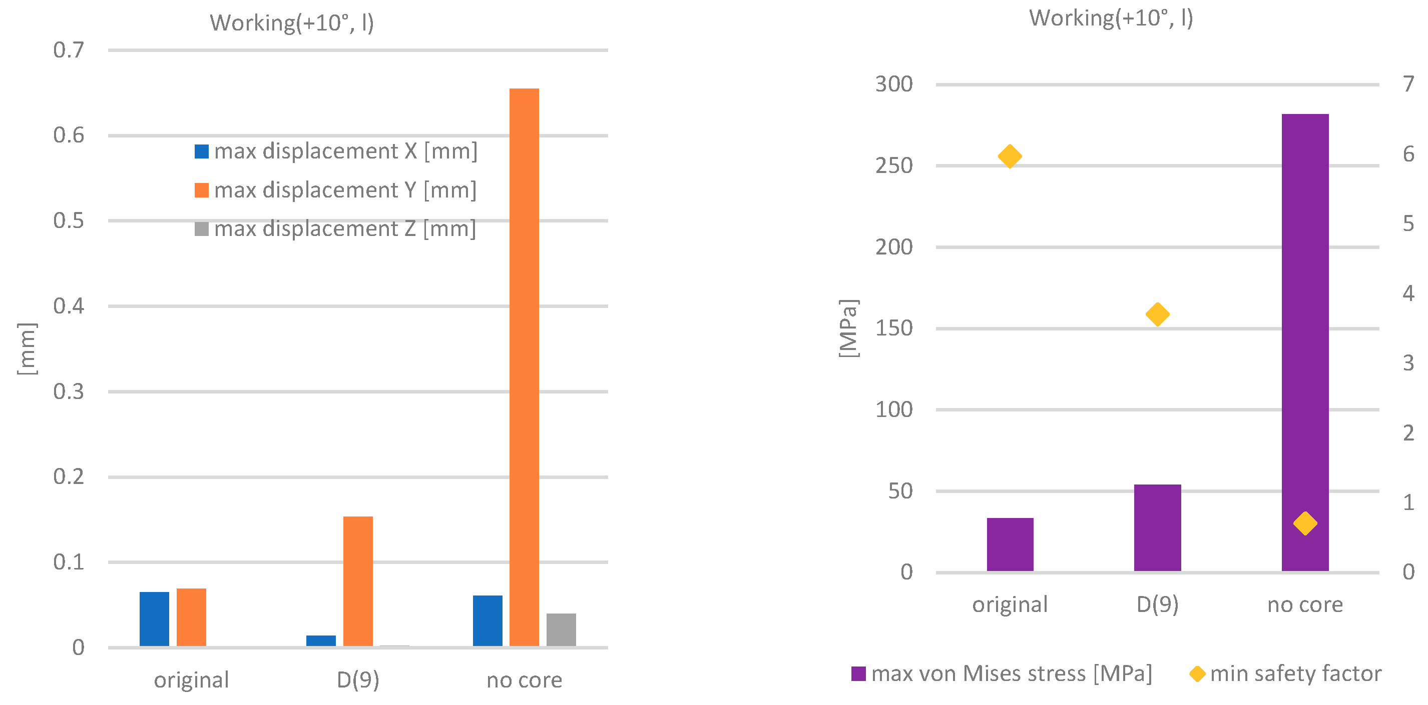
- Lift force () generated on rudder accounts approximately for the of the overall lift required, however, due to the changing attack angle, the wing may transmit a variable load. To account for this variation, it is considered to have to be equal to for attack angle, with a direction perpendicular with respect to bulb–wing interface. A magnitude of was assumed with inclinations of with respect to the interface, to account for magnitude and direction variability load cases. The overall drag force () due to the relative motion of the wing and the water, transmitted to the bulb is estimated to be approximately at while increasing up to about in magnitude for attack angle.
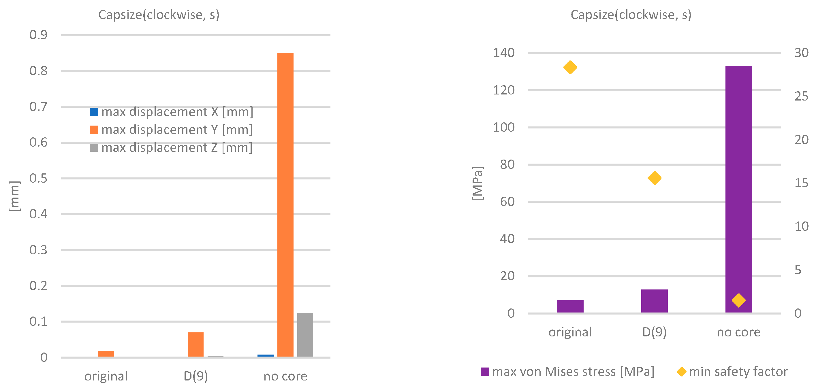
- Exceptional circumstances may lead to boat roll up to capsize, during such event, or after, while recovering, the wing opposes resistance to fluid, or it may be used as lever for boat recovery. These situations may be emulated on the bulb by means of a torque action (). The value considered is . This value simulates a force of applied at , as it is approximately the distance of one wing extremity.
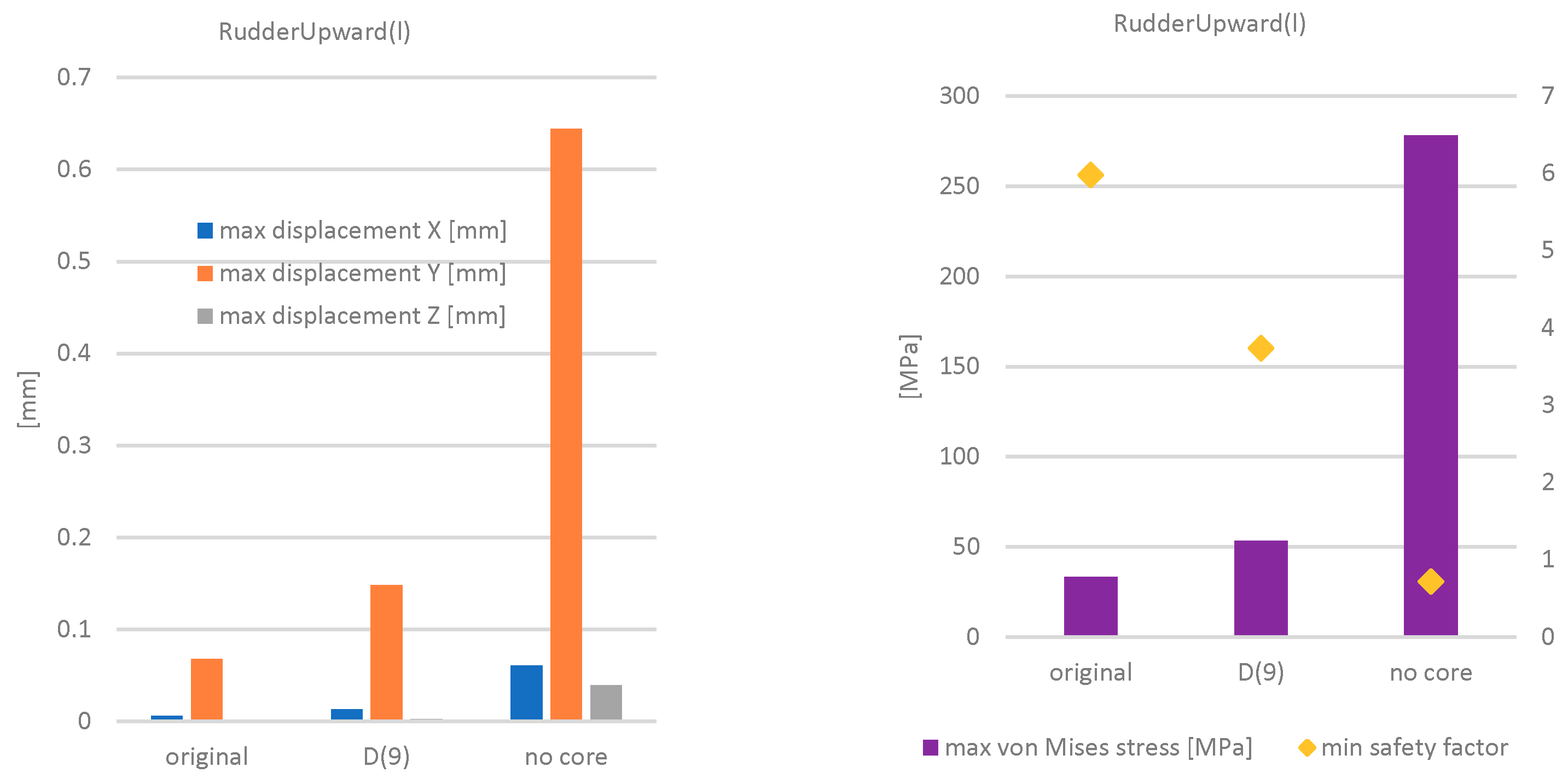
- It may happen that the rudder is carried upward due to boat rapid pitch angle change. As a consequence, the wing acts as hydrodynamic resistance, trying to force downward the bulb rear portion with it. The load () is estimated to be at max . This load is transmitted to the bulb body by means of wing connecting bolts.
- Bulb overall drag force () at max boat speed condition was estimated to be about . However, for simplicity no change in magnitude was set when dealing with different attack angle conditions.
- During the assembly, the compression state imposed by bolts preload should be considered. Rudder vertical bolt preload () is while preloads on wing bolts ( and ) are each.
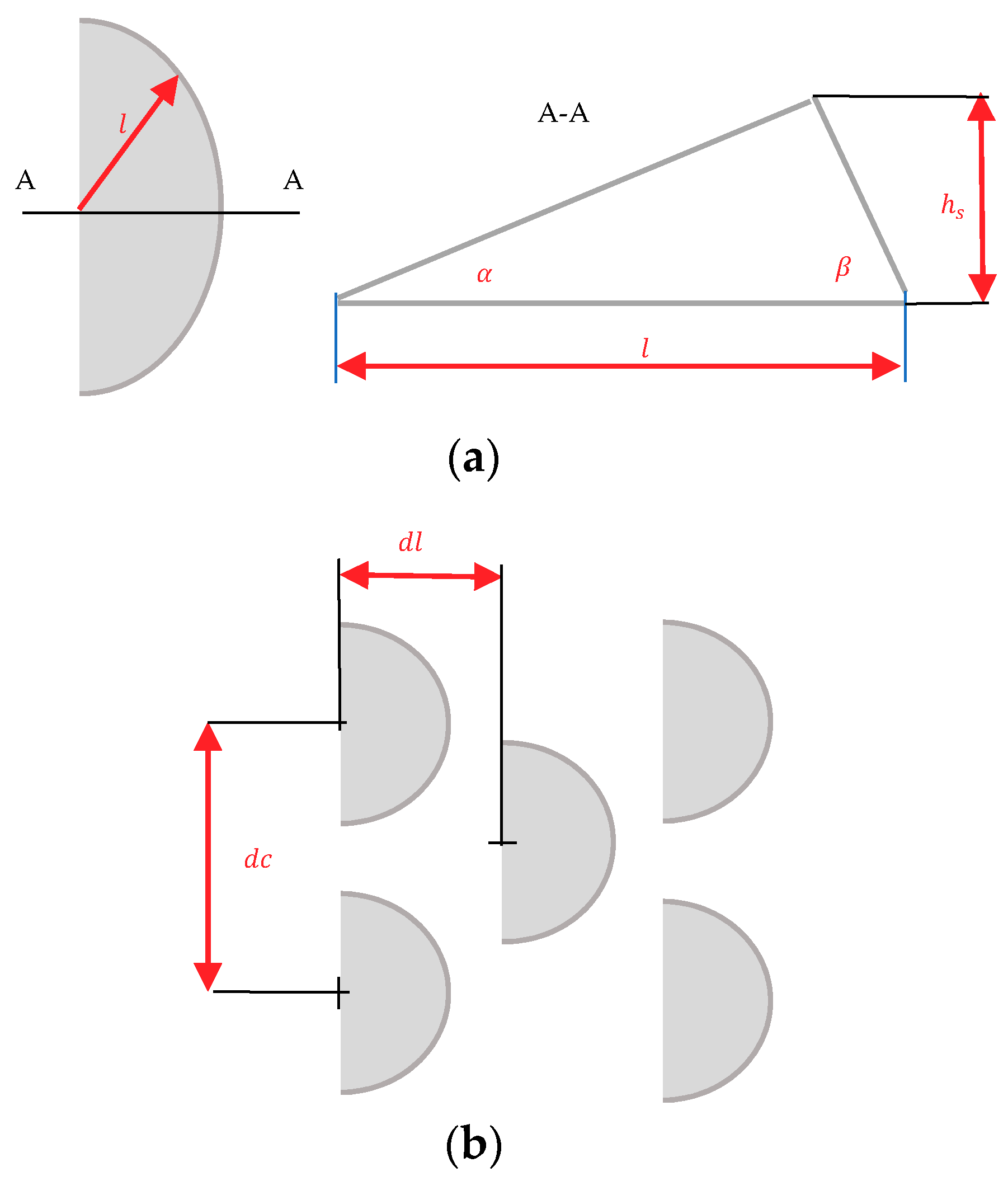
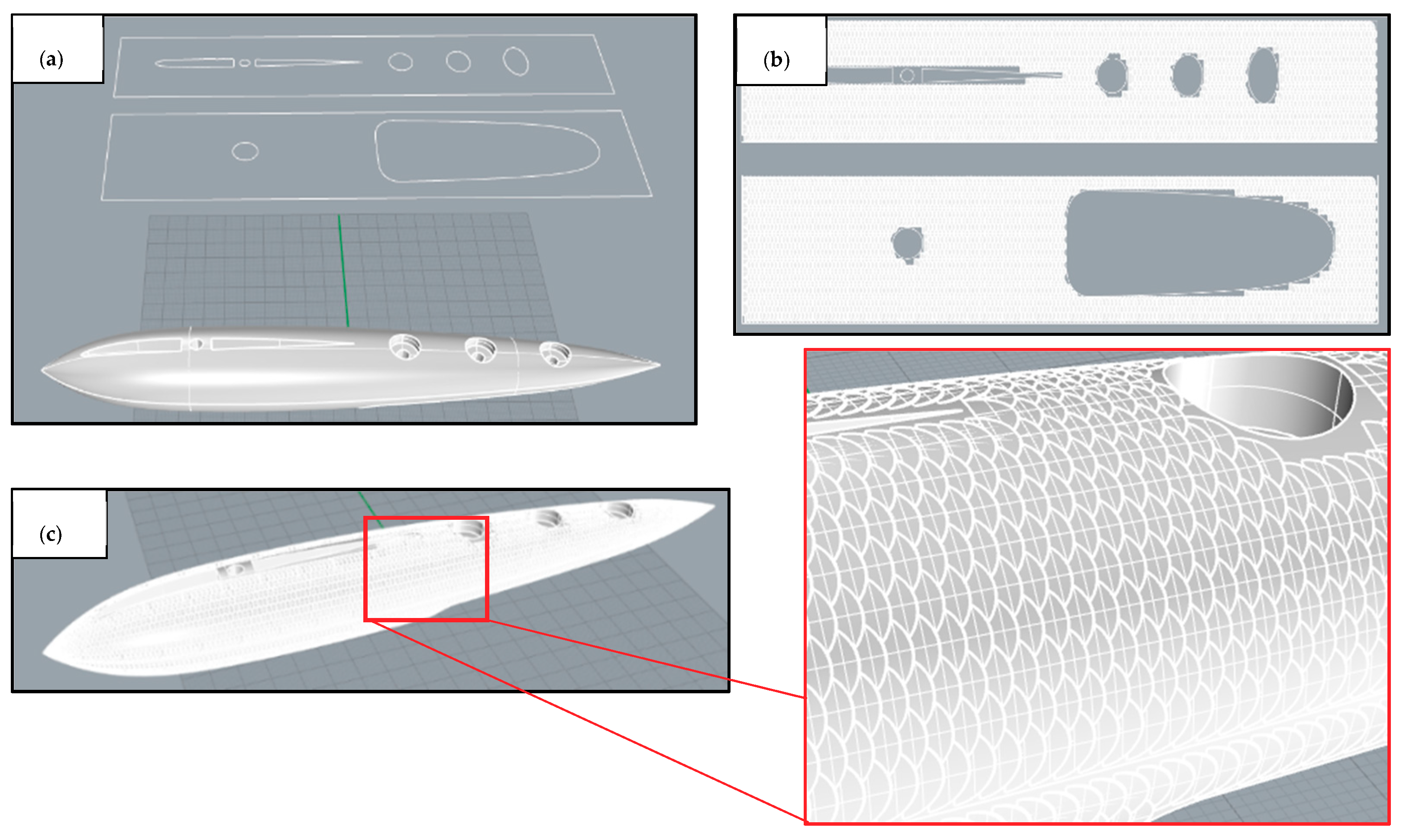
2.4. Biomimetic Texture Design
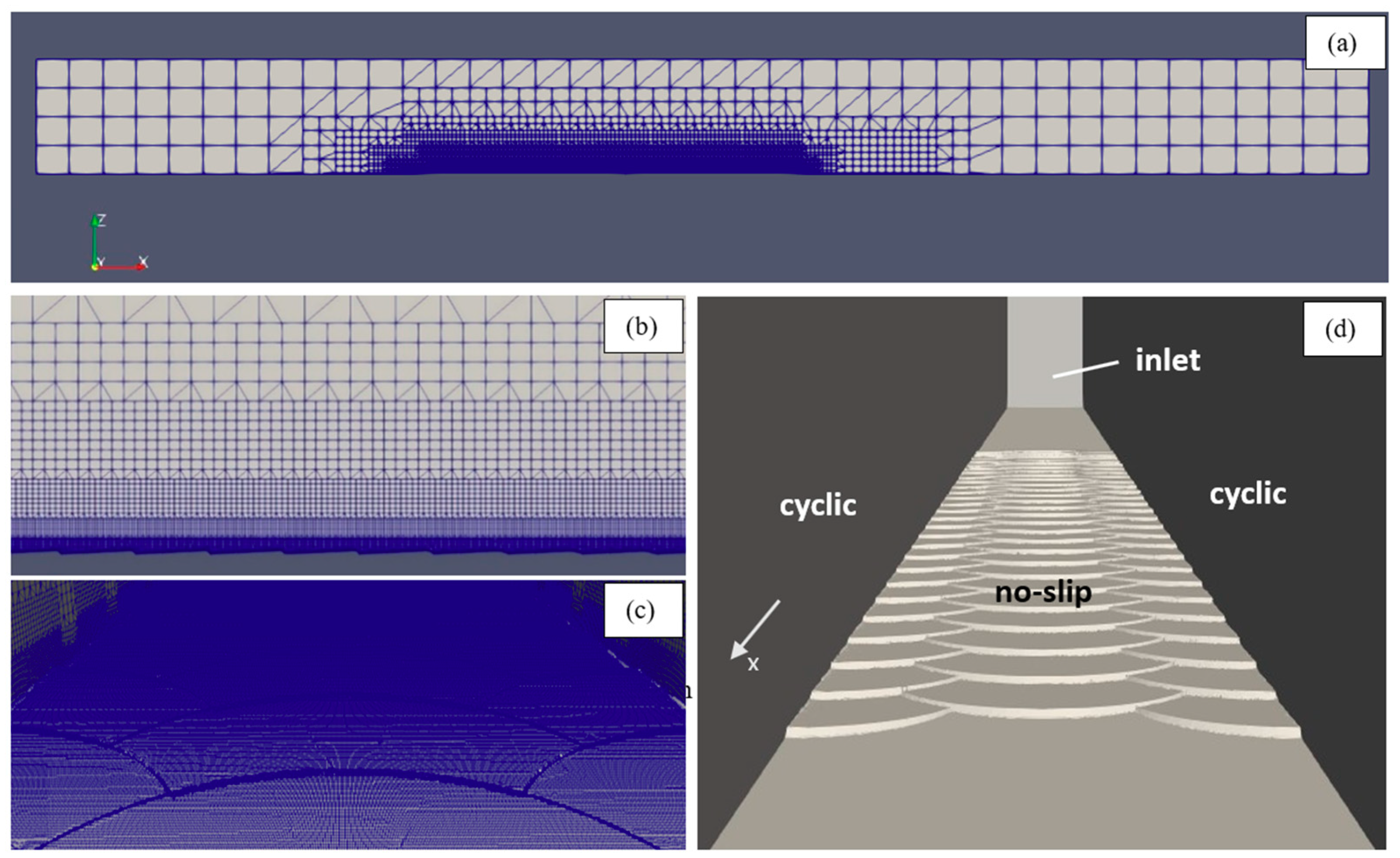
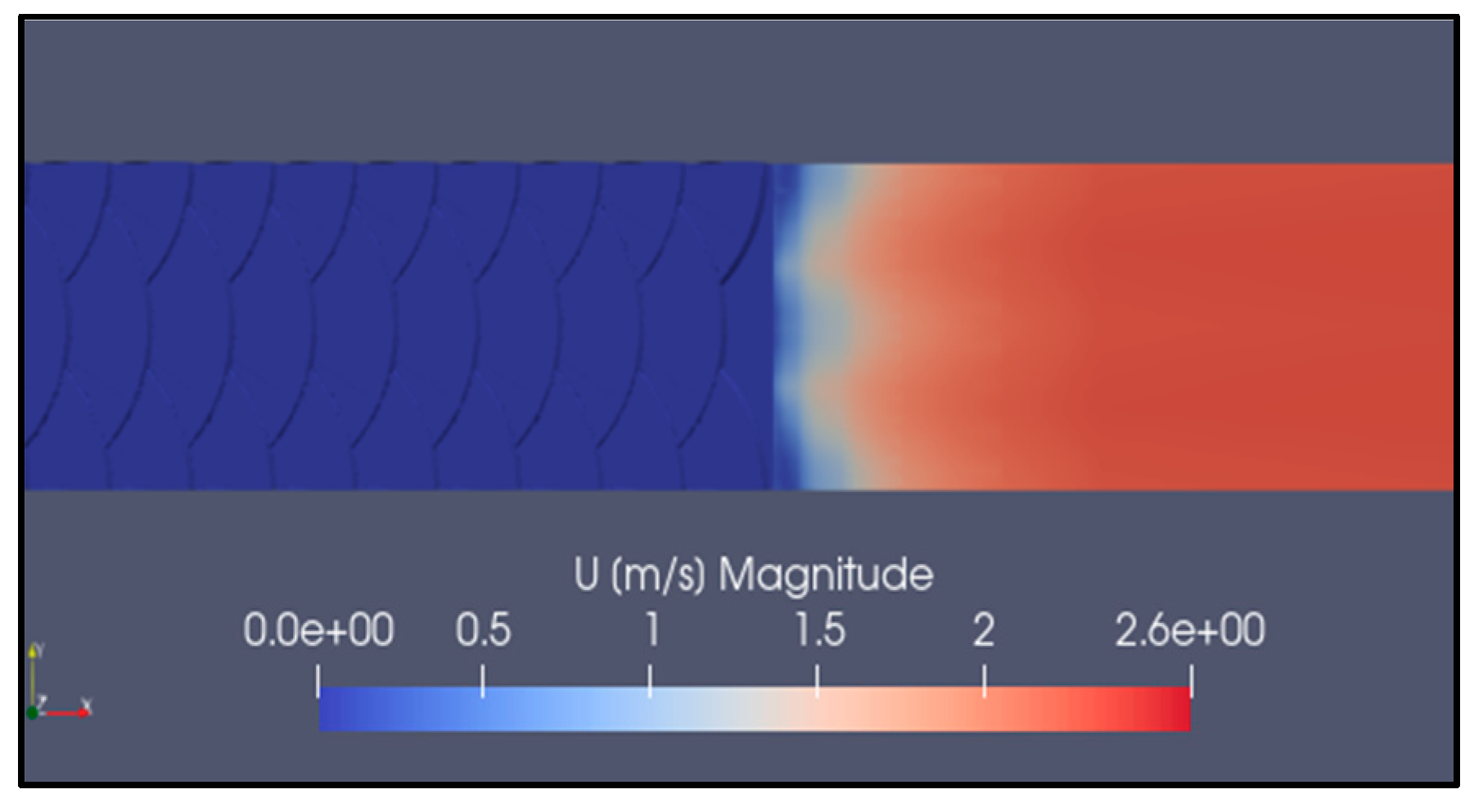
2.5. Fluid Dynamic Behavior of the Fish Scale
3. Materials and Experimental Systems
3.1. Laser Powder Bed Fusion System
3.2. Surface Finishing
3.3. Tensile Test
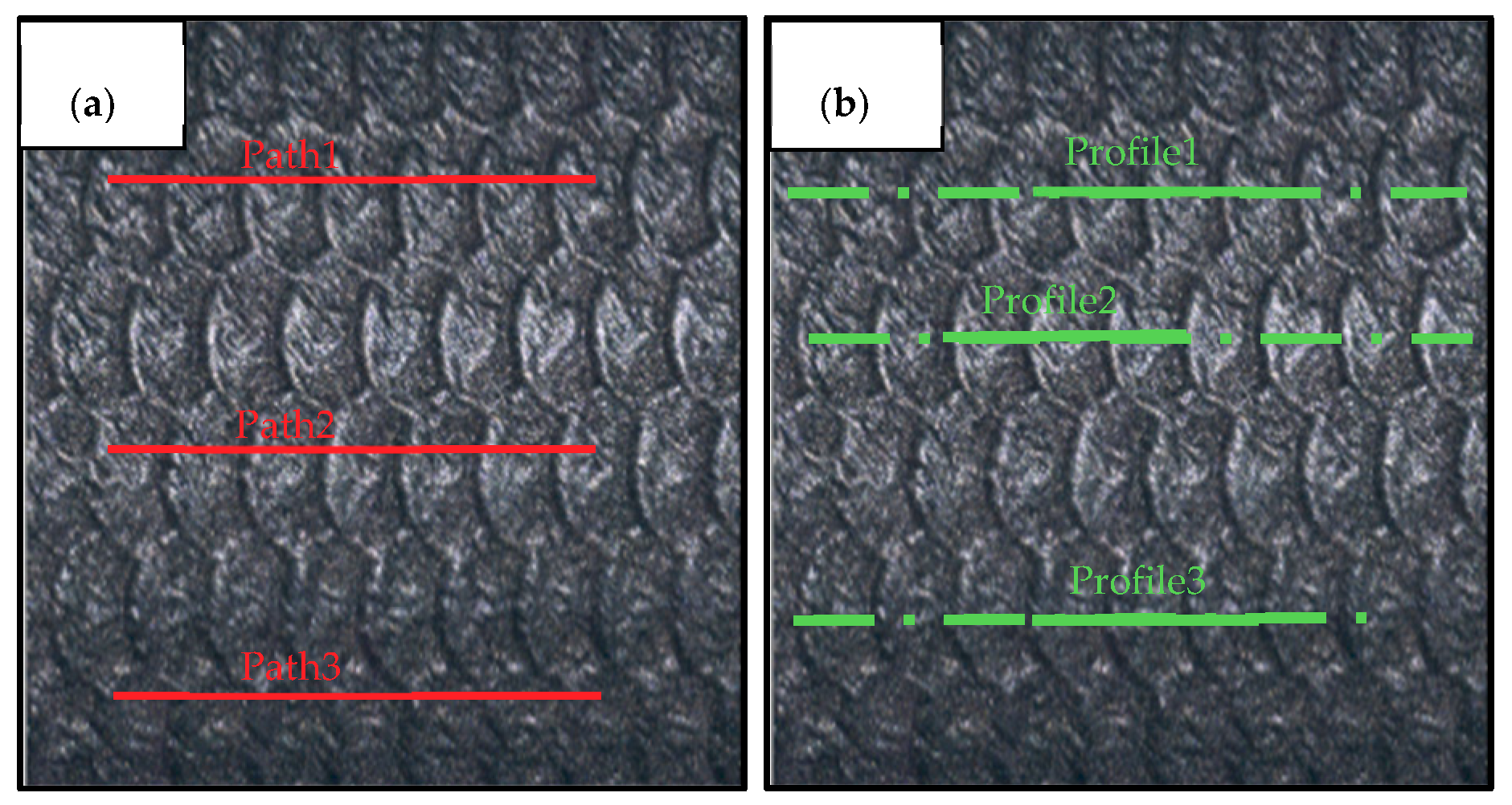
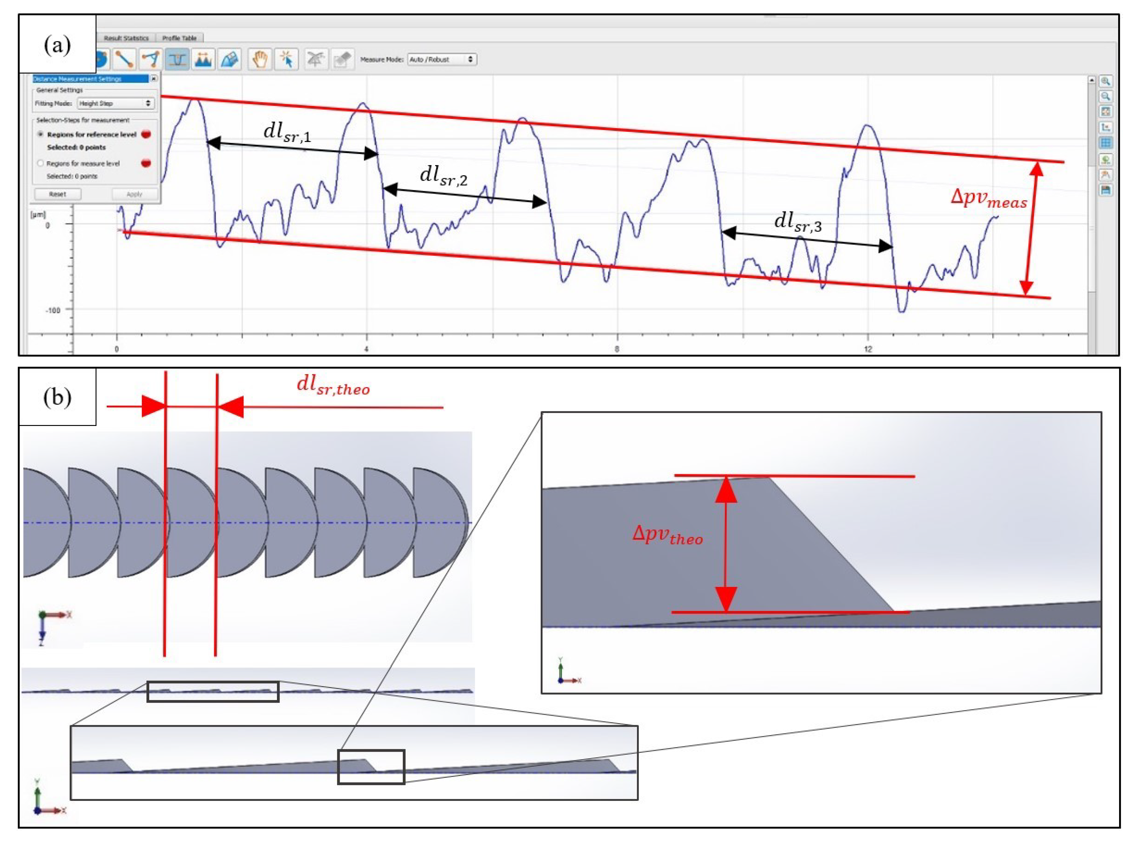
3.4. Surface Analysis
4. Results and Discussion
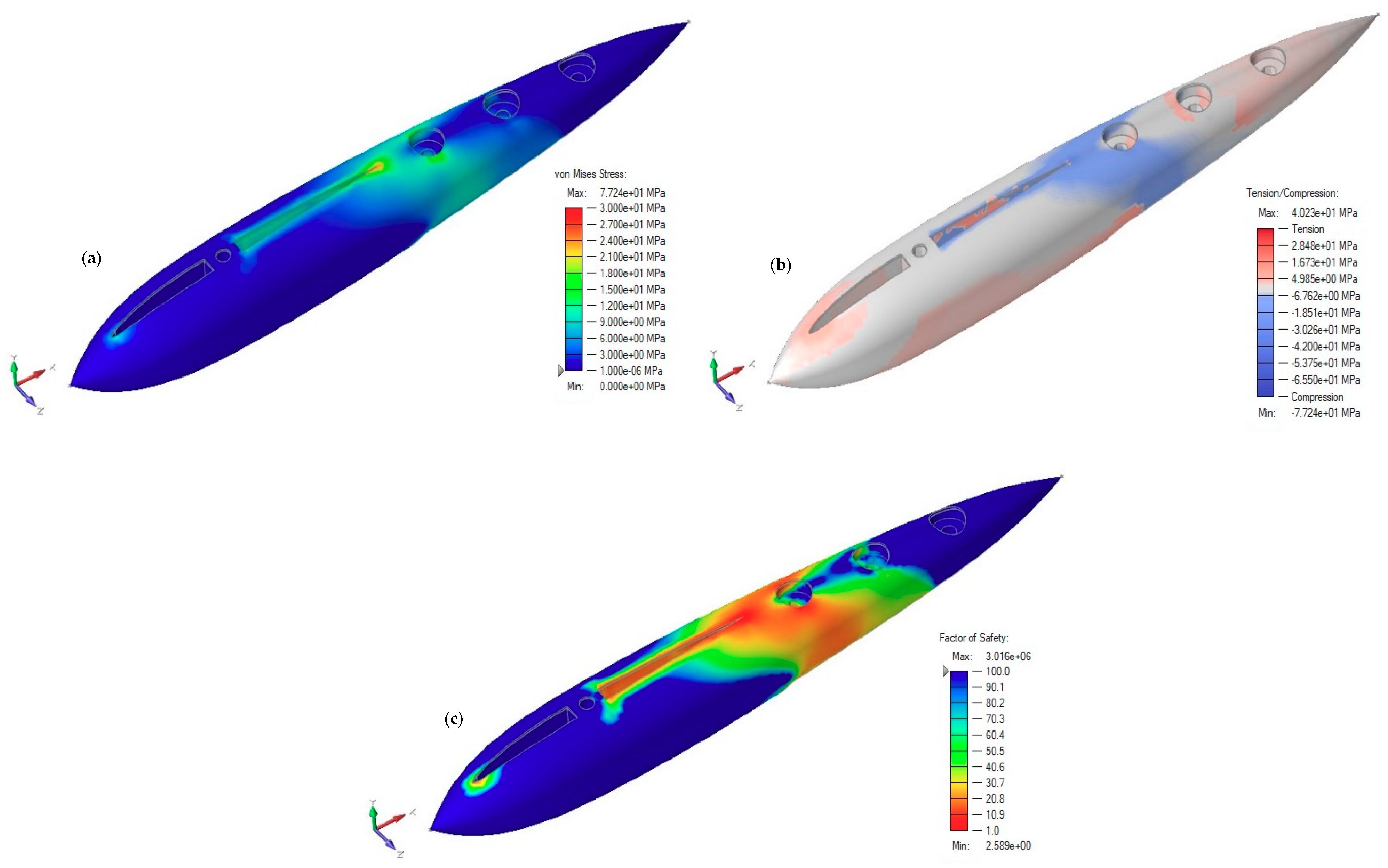
4.1. Topology Optimized Model
4.2. Drag Reduction
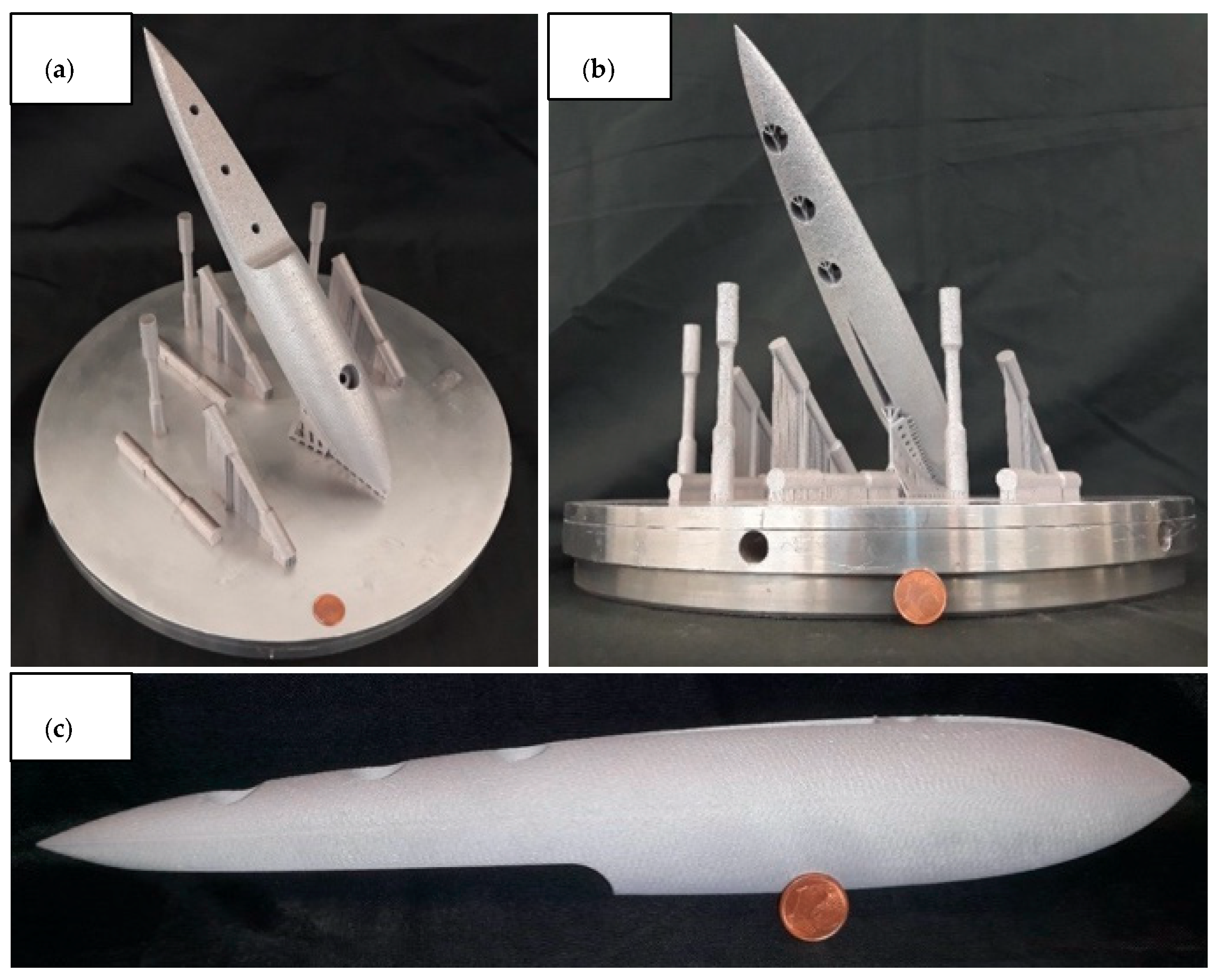
4.3. Bulb Production
4.4. Surface and Material Properties
5. Conclusions
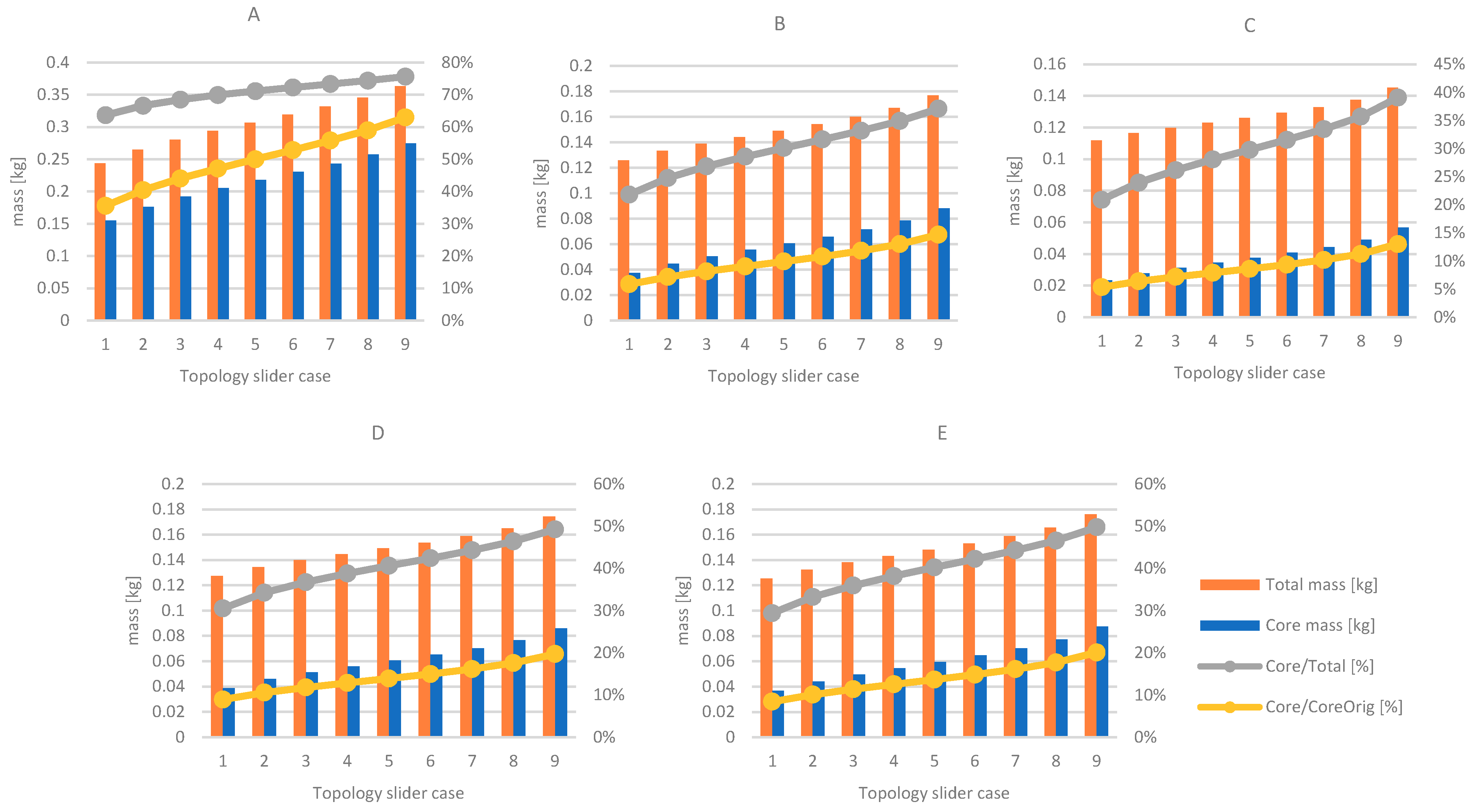
- The design step satisfied the mass reduction target. The core mass was reduced by 80.3% (corresponding to of the original core mass) with acceptable increase in elastic deformations and maximum displacements in the order of for the most critical load cases. The final mass composed of the shell and core was reduced by from 452 to 190 g.
- The biomimetic fish scale surfaces were modeled to understand their fluid dynamic behavior. The results showed improved behavior in terms of viscous drag force component which sees a reduction of about .
- The designed rudder hub was manufactured along with specimens to verify the mechanical behavior of the build. The results showed high geometrical fidelity of the scale details, acceptable surface roughness after sandblasting and the desired mechanical properties.
- The results confirm the great potential of using metal AM processes in the naval industry as it combined great geometrical flexibility as well as design and manufacturing in a digital environment. Along with the obtained results, the work shows a framework for the design, manufacturing and verification of the metal AM products for the naval industry with novel features.
Author Contributions
Funding
Data Availability Statement
Acknowledgments
Conflicts of Interest
Appendix A. Load Cases

| Load Case | Description | Loads |
|---|---|---|
| Working (0°) | Rudder cruising with 0° wing attack angle | , , , , , |
| Working (+10°) | Rudder cruising with +10° wing attack angle | , , , , , |
| Working ( −10°) | Rudder cruising with −10° wing attack angle | , , , , , |
| Capsize (clockwise) | Rudder rotation in correspondence of bulb longitudinal axis clockwise | , , , |
| Capsize (counterclockwise) | Rudder rotation in correspondence of bulb longitudinal axis counterclockwise | , , , |
| RudderUpward | Rudder carried upward by boat vertical translation | , , , |

| Load Case | Description | Loads |
|---|---|---|
| Working (0°, s) | Rudder cruising with 0° wing attack angle and short configuration | , , , , , |
| Working (+10°, s) | Rudder cruising with +10° wing attack angle and short configuration | , , , , , |
| Working (−10°, s) | Rudder cruising with −10° wing attack angle and short configuration | , , , , , |
| Capsize (clockwise, s) | Rudder rotation in correspondence of bulb longitudinal axis clockwise and short configuration | , , , |
| Capsize (counterclockwise, s) | Rudder rotation in correspondence of bulb longitudinal axis counterclockwise and short configuration | , , , |
| RudderUpward (s) | Rudder carried upward by boat vertical translation and short configuration | , , , |
| Working (0°, l) | Rudder cruising with 0° wing attack angle and long configuration | , , , , , |
| Working (+10°, l) | Rudder cruising with +10° wing attack angle and long configuration | , , , , , |
| Working (−10°, l) | Rudder cruising with −10° wing attack angle and long configuration | , , , , , |
| Capsize (clockwise, l) | Rudder rotation in correspondence of bulb longitudinal axis clockwise and long configuration | , , |
| Capsize (counterclockwise, l) | Rudder rotation in correspondence of bulb longitudinal axis counterclockwise and long configuration | , , , |
| RudderUpward (l) | Rudder carried upward by boat vertical translation and long configuration | , , , |


Appendix B. Topological Optimization Runs

Appendix C. Rudder Bulb Model Design and Support Preparation


References
- Ramirez-Peña, M.; Sotano, A.J.S.; Pérez-Fernandez, V.; Abad, F.J.; Batista, M. Achieving a sustainable shipbuilding supply chain under I4.0 perspective. J. Clean. Prod. 2020, 244, 118789. [Google Scholar] [CrossRef]
- University of Maine. Available online: https://composites.umaine.edu/3dirigo-the-worlds-largest-3d-printed-boat/ (accessed on 7 May 2020).
- Braghin, F. Tecnologie Free-form per la Realizzazione di Componenti Nautici Tramite Fiber Placement. In NAUTICA +++ | Additive Manufacturing in campo Navale e Nautico | Arianna Bionda e Andrea Ratti; Edizioni Poli.design: Milano, Italy, 2017; ISBN 978-88-95651-11-8. [Google Scholar]
- Tecniche Nuove Spa, Mini 650. Available online: https://www.plastix.it/mini-650-ocore-stampa-3d/ (accessed on 29 April 2020).
- Cevola, D. Fabbricazione Additiva nel Comparto Nautico: Nuovi Scenari e Prospettive. In NAUTICA +++. Additive Manufacturing in Campo Navale e Nautico | Arianna Bionda e Andrea Ratti; Edizioni Poli.design: Milano, Italy, 2017; ISBN 978-88-95651-11-8. [Google Scholar]
- Nemani, A.V.; Ghaffari, M.; Nasiri, A. Comparison of microstructural characteristics and mechanical properties of shipbuilding steel plates fabricated by conventional rolling versus wire arc additive manufacturing. Addit. Manuf. 2020, 32, 101086. [Google Scholar] [CrossRef]
- Horgar, A.; Fostervoll, H.; Nyhus, B.; Ren, X.; Eriksson, M.; Akselsen, O. Additive manufacturing using WAAM with AA5183 wire. J. Mater. Process. Technol. 2018, 259, 68–74. [Google Scholar] [CrossRef]
- Torims, T.; Pikurs, G.; Ratkus, A.; Logins, A.; Vilcāns, J.; Sklariks, S. Development of Technological Equipment to Laboratory Test In-situ Laser Cladding for Marine Engine Crankshaft Renovation. Procedia Eng. 2015, 100, 559–568. [Google Scholar] [CrossRef] [Green Version]
- Korsmik, R.S.; Rodionov, A.A.; Korshunov, V.A.; Ponomarev, D.A.; Prosychev, I.S.; Promakhov, V.V. Topological optimization and manufacturing of vessel propeller via LMD-method. Mater. Today Proc. 2020, 30, 538–544. [Google Scholar] [CrossRef]
- Liravi, M.; Pakzad, H.; Moosavi, A.; Nouri-Borujerdi, A. A comprehensive review on recent advances in superhydrophobic surfaces and their applications for drag reduction. Prog. Org. Coat. 2020, 140, 105537. [Google Scholar] [CrossRef]
- Aboulkhair, N.T.; Simonelli, M.; Parry, L.; Ashcroft, I.; Tuck, C.; Hague, R. 3D printing of Aluminium alloys: Additive Manufacturing of Aluminium alloys using selective laser melting. Prog. Mater. Sci. 2019, 106, 100578. [Google Scholar] [CrossRef]
- Park, S.H.; Lee, I. Optimization of drag reduction effect of air lubrication for a tanker model. Int. J. Nav. Archit. Ocean Eng. 2018, 10, 427–438. [Google Scholar] [CrossRef]
- Pujals, G.; Depardon, S.; Cossu, C.; Pujals, G.; Depardon, S.; Cossu, C. Drag reduction of a 3D bluff body using coherent streamwise streaks. Exp. Fluids 2010, 5, 1085–1094. [Google Scholar] [CrossRef] [Green Version]
- Fu, Y.F.; Yuan, C.Q.; Bai, X.Q. Marine drag reduction of shark skin inspired riblet surfaces. Biosurface Biotribology 2017, 3, 11–24. [Google Scholar] [CrossRef]
- Ibrahim, M.D.; Amran, S.N.A.; Yunos, Y.S.; Rahman, M.R.A.; Mohtar, M.Z.; Wong, L.K.; Zulkharnain, A. The Study of Drag Reduction on Ships Inspired by Simplified Shark Skin Imitation. Appl. Bionics Biomech. 2018, 2018, 1–11. [Google Scholar] [CrossRef] [PubMed] [Green Version]
- Ran, W.; Zare, A.; Jovanović, M.R. Model-Based Design of Riblets for Turbulent Drag Reduction. February 2020. Available online: http://arxiv.org/abs/2002.01671 (accessed on 5 June 2020).
- Song, X.; Zhang, M. Turbulent Drag Reduction Characteristics of Bionic Nonsmooth Surfaces with Jets. Appl. Sci. 2019, 9, 5070. [Google Scholar] [CrossRef] [Green Version]
- Bai, J.; Meng, X.; Ji, C.; Liang, Y. Drag reduction characteristics and flow field analysis of textured surface. Friction 2016, 4, 165–175. [Google Scholar] [CrossRef] [Green Version]
- Hu, H.; Tamai, M.; Murphy, J.T. Flexible-Membrane Airfoils at Low Reynolds Numbers. J. Aircr. 2008, 45, 1767–1778. [Google Scholar] [CrossRef]
- Banks, J.; Giovannetti, L.M.; Taylor, J.; Turnock, S. Assessing Human-Fluid-Structure Interaction for the International Moth. Procedia Eng. 2016, 147, 311–316. [Google Scholar] [CrossRef] [Green Version]
- Giovannetti, L.M.; Banks, J.; Ledri, M.; Turnock, S.; Boyd, S. Toward the development of a hydrofoil tailored to passively reduce its lift response to fluid load. Ocean Eng. 2018, 167, 1–10. [Google Scholar] [CrossRef] [Green Version]
- International Sailing Federation. International Moth Class Rules. 1 May 2017. Available online: http://www.moth-sailing.org/history/rules-and-documents/ (accessed on 1 February 2020).
- Pereira, J.C.; Gil, E.; Solaberrieta, L.; Sebastián, M.S.; Bilbao, Y.; Rodríguez, P.P. Comparison of AlSi7Mg0.6 alloy obtained by selective laser melting and investment casting processes: Microstructure and mechanical properties in as-built/as-cast and heat-treated conditions. Mater. Sci. Eng. A 2020, 778, 139124. [Google Scholar] [CrossRef]
- Muthuramalingam, M.; Villemin, L.S.; Bruecker, C. Streak formation in flow over biomimetic fish scale arrays. J. Exp. Biol. 2019, 222. [Google Scholar] [CrossRef] [Green Version]
- Rao, H.; Giet, S.; Yang, K.; Wu, X.; Davies, C. The influence of processing parameters on aluminium alloy A357 manufactured by Selective Laser Melting. Mater. Des. 2016, 109, 334–346. [Google Scholar] [CrossRef]
- Rao, J.H.; Zhang, Y.; Fang, X.; Chen, Y.; Wu, X.; Davies, C.H. The origins for tensile properties of selective laser melted aluminium alloy A357. Addit. Manuf. 2017, 17, 113–122. [Google Scholar] [CrossRef]
- Trevisan, F.; Calignano, F.; Lorusso, M.; Pakkanen, J.; Ambrosio, E.P.; Lombardi, M.; Pavese, M.; Manfredi, D.; Fino, P. Effects of Heat Treatments on A357 Alloy Produced by Selective Laser Melting. In Proceedings of the World PM 2016 Congress Exhibition: European Powder Metallurgy Association, Hamburg, Germany, 9–13 October 2016; pp. 1–7. [Google Scholar]
- Aversa, A.; Lorusso, M.; Trevisan, F.; Ambrosio, E.P.; Calignano, F.; Manfredi, D.G.; Biamino, S.; Fino, P.; Lombardi, M.; Pavese, M. Effect of Process and Post-Process Conditions on the Mechanical Properties of an A357 Alloy Produced via Laser Powder Bed Fusion. Metals 2017, 7, 68. [Google Scholar] [CrossRef]
- Grande, A.M.; Cacace, A.; Demir, A.G.; Sala, G. Fracture and fatigue behaviour of AlSi7Mg0. 6 produced by Selective Laser Melting: Effects of thermal-treatments. In Proceedings of the 25th Conference of the Italian Association of Aeronautics and Astronautics (AIDAA 2019) AIDAA, Rome, Italy, 9–12 September 2019; pp. 1138–1144. [Google Scholar]
- Sorci, R.; Tassa, O.; Colaneri, A.; Astri, A.; Mirabile, D.; Iwnicki, S.; Demir, A.G. Design of an Innovative Oxide Dispersion Strengthened Al Alloy for Selective Laser Melting to Produce Lighter Components for the Railway Sector. J. Mater. Eng. Perform. 2021, 30, 1–11. [Google Scholar] [CrossRef]
- Garavaglia, M.; Demir, A.G.; Zarini, S.; Victor, B.M.; Previtali, B. Fiber laser welding of AA 5754 in the double lap-joint configuration: Process development, mechanical characterization, and monitoring. Int. J. Adv. Manuf. Technol. 2020, 111, 1643–1657. [Google Scholar] [CrossRef]
- Mäkikangas, J.; Rautio, T.; Mustakangas, A.; Mäntyjärvi, K. Laser welding of AlSi10Mg aluminium-based alloy produced by Selective Laser Melting (SLM). Procedia Manuf. 2019, 36, 88–94. [Google Scholar] [CrossRef]


| Load | Description | Symbol | Unit | Magnitude |
|---|---|---|---|---|
| Lift force | Rudder wing lift action | [] | 600 | |
| [] | 400 | |||
| [] | 400 | |||
| Wing drag force | Rudder wing motion with respect to water | [] | 34 | |
| [] | 50 | |||
| [] | 50 | |||
| Capsize torque | Torque due to capsizing of boat | [] | 6.25 | |
| Wing vertical resistance | Resistance to vertical translation of the wing | [] | 400 | |
| Bulb drag force | Bulb motion with respect to water | [] | 50 | |
| Rudder vertical bolt preload | Compression due to assembly | [] | 60 | |
| Wing bolts preloads | Compression due to assembly | [] | 125 | |
| [] | 125 |
| [] | [] | [] | [] |
| 3 | 3 | 0.9 | 6 |
| Process Parameters | Level | |
|---|---|---|
| Chamber oxygen concentration | [%] | 0.1 |
| Inert gas type | [–] | Ar |
| Shielding gas flow rate | [] | 0.8 |
| Preheating temperature () | 100 | |
| Laser spot diameter () | [] | 100 |
| Layer thickness () | [] | 50 |
| Layer scan strategy | [–] | No pattern |
| Scan direction rot. layer by layer | [] | 67 |
| Laser power () | [] | 345 |
| Scan speed () | [] | 1500 |
| Hatch distance () | [] | 0.10 |
| Run Name | Mass Target | Overhang Control | Core Mass | Core Mass |
|---|---|---|---|---|
| [] wrt. Original | [Yes/No] | [] | [] wrt. Original | |
| A | 50 | No | 0.218 | 50 |
| B | 15 | No | 0.061 | 14 |
| C | 10 | No | 0.038 | 9 |
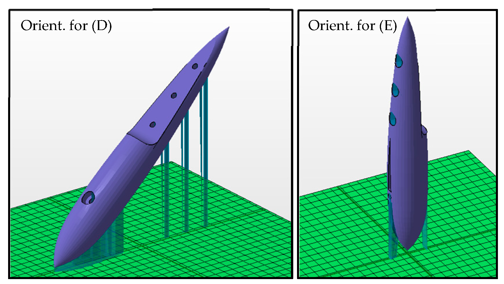
| D | 15 | Yes—45° printing orientation | 0.061 | 14 |
| E | 15 | Yes—90° printing orientation | 0.059 | 14 |
| Condition | ||||||
|---|---|---|---|---|---|---|
| [] | [] | [] | [] | [] | [] | |
| As-built | 11.9 | 15.8 | 1800 | 1787 | 89.94 | 99.11 |
| Sandblasted | 7.13 | 9.09 | 1800 | 1888 | 89.94 | 84.29 |
Publisher’s Note: MDPI stays neutral with regard to jurisdictional claims in published maps and institutional affiliations. |
© 2021 by the authors. Licensee MDPI, Basel, Switzerland. This article is an open access article distributed under the terms and conditions of the Creative Commons Attribution (CC BY) license (https://creativecommons.org/licenses/by/4.0/).
Share and Cite
Scarpellini, A.; Finazzi, V.; Schito, P.; Bionda, A.; Ratti, A.; Demir, A.G. Laser Powder Bed Fusion of a Topology Optimized and Surface Textured Rudder Bulb with Lightweight and Drag-Reducing Design. J. Mar. Sci. Eng. 2021, 9, 1032. https://doi.org/10.3390/jmse9091032
Scarpellini A, Finazzi V, Schito P, Bionda A, Ratti A, Demir AG. Laser Powder Bed Fusion of a Topology Optimized and Surface Textured Rudder Bulb with Lightweight and Drag-Reducing Design. Journal of Marine Science and Engineering. 2021; 9(9):1032. https://doi.org/10.3390/jmse9091032
Chicago/Turabian StyleScarpellini, Alessandro, Valentina Finazzi, Paolo Schito, Arianna Bionda, Andrea Ratti, and Ali Gökhan Demir. 2021. "Laser Powder Bed Fusion of a Topology Optimized and Surface Textured Rudder Bulb with Lightweight and Drag-Reducing Design" Journal of Marine Science and Engineering 9, no. 9: 1032. https://doi.org/10.3390/jmse9091032