As-Built Simulation of the High Flux Isotope Reactor †
by
 ,
,
Benjamin R. Betzler
1,*, 
David Chandler
1,
Thomas M. Evans
1,
Gregory G. Davidson
1,
Charles R. Daily
1,
Stephen C. Wilson
2 and
Scott W. Mosher
2 1
Oak Ridge National Laboratory, 1 Bethel Valley Rd., Oak Ridge, TN 37831, USA
2
Los Alamos National Laboratory, P.O. Box 1663, Los Alamos, NM 87545, USA
*
Author to whom correspondence should be addressed.
†
This manuscript has been authored by UT-Battelle, LLC, under contract DE-AC05-00OR22725 with the US Department of Energy (DOE). The US government retains and the publisher, by accepting the article for publication, acknowledges that the US government retains a nonexclusive, paid-up, irrevocable, worldwide license to publish or reproduce the published form of this manuscript, or allow others to do so, for US government purposes. DOE will provide public access to these results of federally sponsored research in accordance with the DOE Public Access Plan (http://energy.gov/downloads/doe-public-access-plan ).
J. Nucl. Eng. 2021, 2(1), 28-34; https://doi.org/10.3390/jne2010003
Submission received: 2 October 2020
/
Accepted: 2 February 2021
/
Published: 7 February 2021
(This article belongs to the Special Issue Selected Papers from PHYSOR 2020)
Abstract
:The Oak Ridge National Laboratory High Flux Isotope Reactor (HFIR) is an 85 MWt flux trap-type research reactor that supports key research missions, including isotope production, materials irradiation, and neutron scattering. The core consists of an inner and an outer fuel element containing 171 and 369 involute-shaped plates, respectively. The thin fuel plates consist of a U3O8-Al dispersion fuel (highly enriched), an aluminum-based filler, and aluminum cladding. The fuel meat thickness is varied across the width of the involute plate to reduce thermal flux peaks at the radial edges of the fuel elements. Some deviation from the designed fuel meat shaping is allowed during manufacturing. A homogeneity scan of each fuel plate checks for potential anomalies in the fuel distribution by scanning the surface of the plate and comparing the attenuation of the beam to calibration standards. While typical HFIR simulations use homogenized fuel regions, explicit models of the plates were developed under the Low-Enriched Uranium Conversion Program. These explicit models typically include one inner and one outer fuel plate with nominal fuel distributions, and then the plates are duplicated to fill the space of the corresponding fuel element. Therefore, data extracted from these simulations are limited to azimuthally averaged quantities. To determine the reactivity and physics impacts of an as-built outer fuel element and generate azimuthally dependent data in the element, 369 unique fuel plate models were generated and positioned. This model generates the three-dimensional (i.e., radial–axial–azimuthal) plate power profile, where the azimuthal profile is impacted by features within the adjacent control element region and beryllium reflector. For an as-built model of the outer fuel element, plate-specific homogeneity data, 235U loading, enrichment, and channel thickness measurements were translated into the model, yielding a much more varied azimuthal power profile encompassed by uncertainty factors in analyses. These models were run with the ORNL-TN and Shift Monte Carlo tools, and they contained upwards of 500,000 cells and 100,000 unique tallies.
1. Introduction
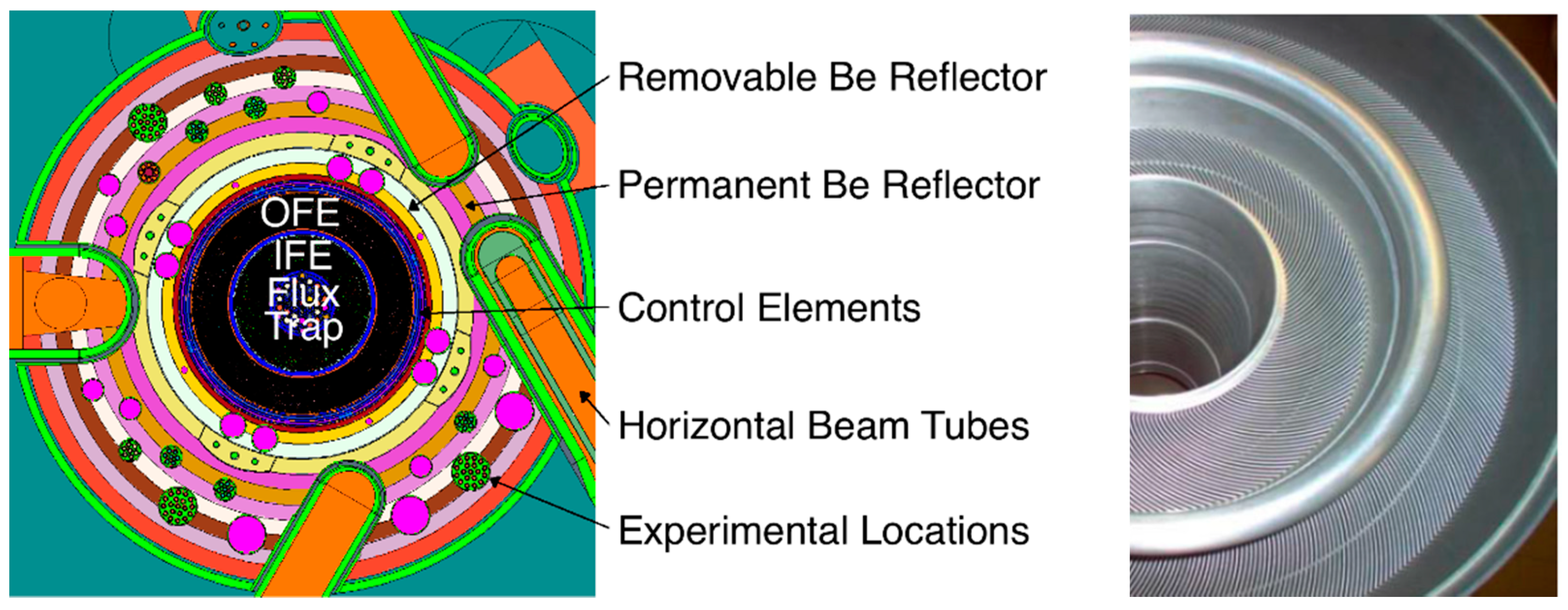
The Oak Ridge National Laboratory High Flux Isotope Reactor (HFIR) is a very high power density research reactor supporting several scientific missions, including neutron scattering, isotope production, and materials irradiation. The water-cooled reactor consists of several concentric cylindrical regions (Figure 1), including a central flux trap, core, control elements, and beryllium reflectors. The core consists of a 171-plate inner fuel element (IFE) and a 369-plate outer fuel element (OFE), each with 1.27 mm thick involute-shaped fuel plates and coolant channel gaps (Figure 1). Each 1.27 mm thick plate consists of a 0.762 mm thick central volume filled with a U3O8-Al dispersion fuel and an Al filler, with additional boron in the IFE filler (Figure 1) [1].
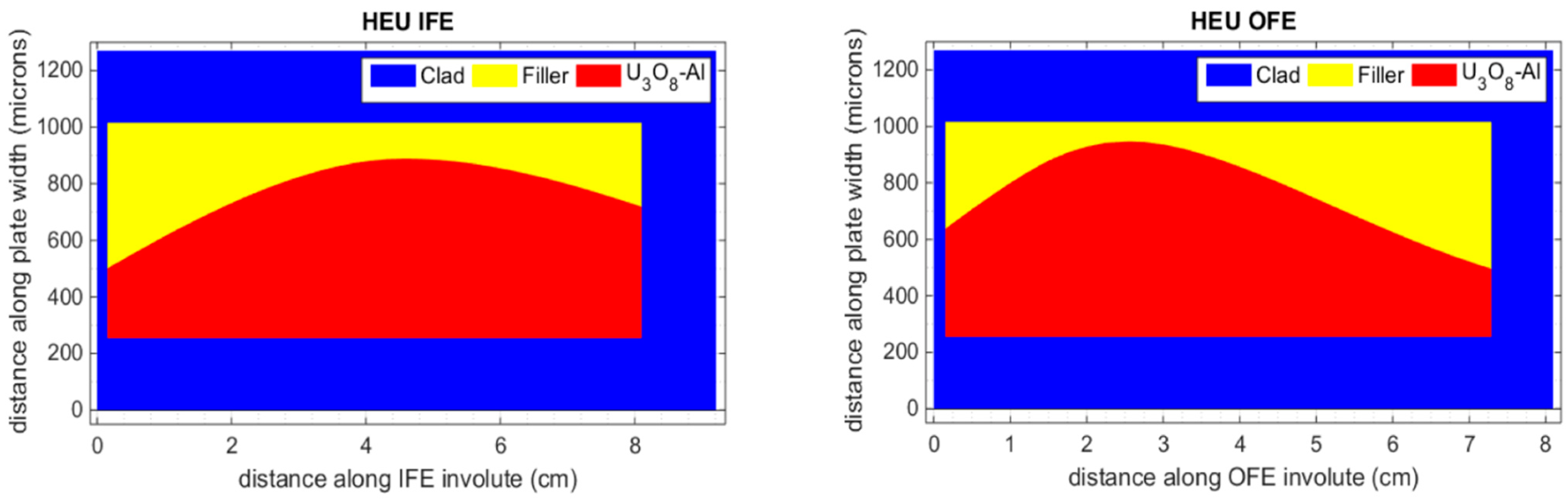
To reduce power peaking at the radial edges of the fuel elements, the thickness of the U3O8-Al fuel mixture is varied along the length of the involute (Figure 2). The as-designed distribution of this fuel mixture was defined in flat-plate geometry (Figure 2) before the plates were curved to final involute form. To accommodate the difficulties in manufacturing processes with such finely detailed geometries, tolerances were defined within the design specifications, and uncertainty factors were used in safety analyses to account for inhomogeneities or other manufacturing variances [2]. Data generated during the manufacturing process quantified this deviation from the designed IFE and OFE. Interpreting and incorporating this data within the highest fidelity models of the HFIR OFE and examining the impact demonstrated the capability of modern modeling and simulation tools and showed the value of as-built simulations.
2. Modeling Tools
Significant efforts through the Low-Enriched Uranium (LEU) Conversion Program have yielded high-fidelity reactor physics models of HFIR, including explicit models of the current highly enriched uranium (HEU) core [3]. These reactor physics models have been fully reviewed and checked, and they serve as the starting point for this analysis: HFIR with an HEU core and a representative target loading.
The Shift Monte Carlo tool [4,5,6] was leveraged by the LEU Conversion Program for design optimization studies due to its scalability and its ability to yield results equivalent to those obtained using software quality assurance tools [4]. Average run times reduced by orders of magnitude yielded accurate results within hours [7]. In addition, the HFIRCON tool developed for high-fidelity multicycle target depletion calculations for HFIR was leveraged. HFIRCON uses the MCNP [8] transport solver with ORNL-TN upgrades [9] and the SCALE/ORIGEN [10] depletion solver to perform time-dependent depletion calculations with automatic detailed heating output.
In design studies for the LEU Conversion Program, fuel meshes, coupling methods, and data formats were generated and thoroughly exercised between reactor physics tools and thermal hydraulic solvers [2,11,12,13,14]. Of particular interest is the fission density and relative fission density distributions within the IFE and OFE fuel plates, which are typically azimuthally integrated quantities due to the transport model. This model explicitly defines one IFE and one OFE fuel plate and duplicates this plate throughout the IFE and OFE regions. The relative fission density takes the fission density distribution and effectively renormalizes it over an overlaid mesh to account for the volumetric distribution of the fuel,
where is the volume of the given mesh region, is the number density of isotope , is the fission cross-section of isotope , is the scalar flux, the sum is over the fissile isotopes within the fuel region, and is a normalization factor defined by the total fissions divided by the volume of the total mesh.
Monte Carlo source convergence is not an issue for small, tightly coupled cores, such as HFIR; calculated Shannon entropy of the Monte Carlo source tends to show source convergence within tens of cycles [7]. Typical HFIR Monte Carlo simulations for LEU and HEU core analysis use 50 inactive cycles, 300 active cycles, and 105 particles per cycle, for a total of 30 106 active particles. This is sufficient for the 43,000-group flux tallies used for fuel region depletion, but it does not provide low-uncertainty results globally, particularly toward the outer edges of the reactor [2,15,16,17,18]. Therefore, more detailed metrics and heat deposition calculations requiring higher confidence in tallies in small cells far from the core use approximately 500 106 active particles [19,20]. Though many quantities tallied for the following analysis were within the fuel, there was additional fidelity in these models, and there was a need to quantify the power distribution within individual fuel plates. Thus, the results shown herein used at least 3 109 active particles to reduce tally uncertainties adequately. In all cases, the calculated Monte Carlo uncertainty was less than 0.5% for single plate quantities and less than 0.1% for azimuthally integrated quantities.
3. As-Built Data
Homogeneity, enrichment, and mass data were taken for each fuel plate that was inserted into the fuel elements. A homogeneity scan effectively measured the fuel distribution within a given plate, which should reflect the as-designed radial distribution of the fuel meat. After the plates were inserted into the elements, the width distribution of each coolant channel between the plates was measured. The result was an indexed set of as-built fuel plate and coolant channel gap data.
Before this data could be incorporated into the explicit HFIR models, it must be remapped onto the existing fuel mesh. The HFIR HEU OFE 14 19 fuel mesh (radial axial) has been shown to capture heat deposition and depletion physics adequately [16,21]. The coolant channel gap was discretized in a similar manner, with additional mesh elements in the unfueled regions, resulting in a 16 21 mesh. Conversely, homogeneity data were taken on a 48 333 mesh, and coolant channel gap data were taken on a 5 461 mesh. For the homogeneity data, the as-built integrated average fuel thickness was coarsened onto the MCNP mesh (Figure 3). This generated an as-built fuel distribution within the plate, which was then adjusted to match the as-built plate mass and enrichment data. For the coolant channel gap data, the nearest neighbor extrapolation and linear interpolation approach in the radial dimension (to convert to a finer mesh) followed an axial integration onto the neutronics mesh. Previous preliminary analyses of as-built data determined that its inclusion would likely reduce conservatism, as the as-built plates are typically underloaded at the radial and axial edges of the active fuel region, where the fission power is typically higher.
4. Results and Discussion
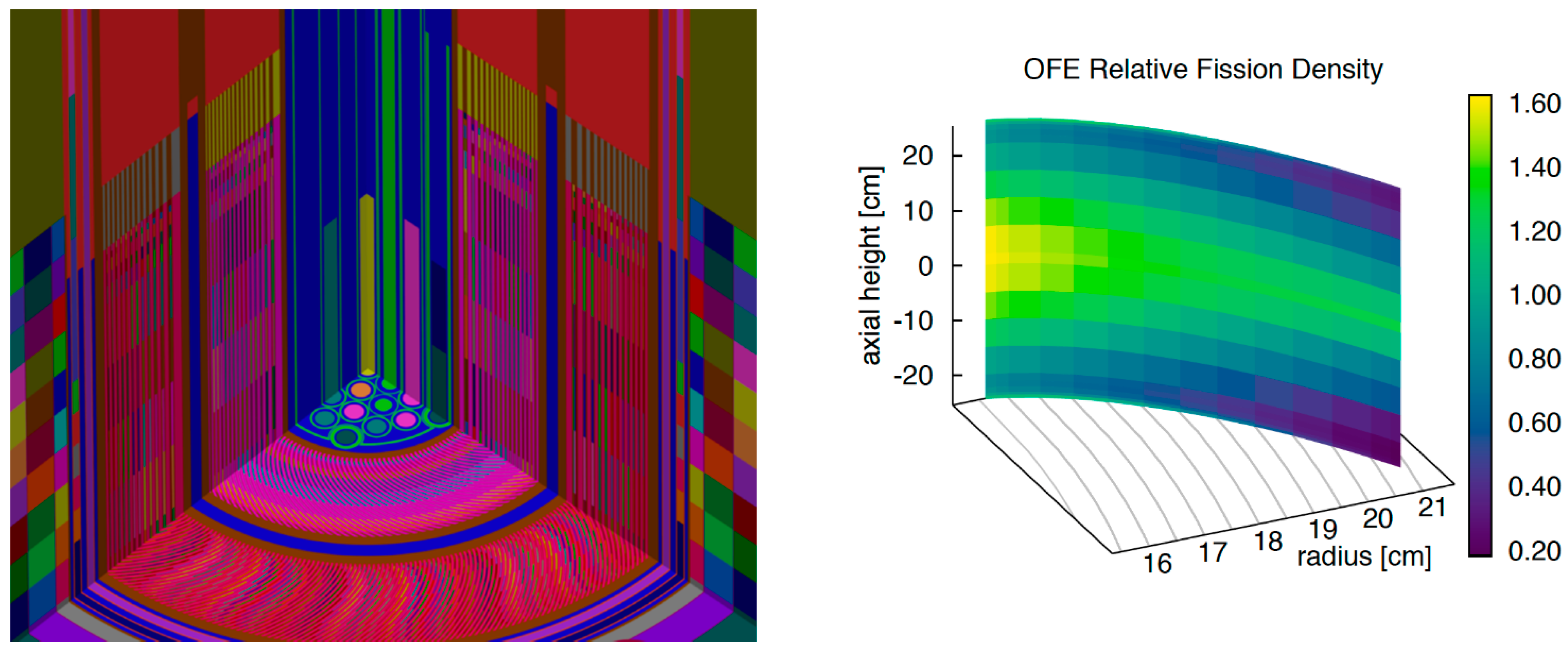
The first step to incorporating this plate-specific data was to build a model that can accept this data: each OFE fuel plate must be explicitly defined. The resulting 369 individual explicit OFE plate model comprised 1.5 million lines of input and nearly 500 thousand cells (Figure 4). Two models were generated: (1) with the as-designed fuel distribution repeated in all fuel plates, and (2) incorporating this as-built data. In all cases, the data were incorporated via density adjustments instead of physical changes to the geometry. This density adjustment approximation introduced negligible error [16]. The as-built OFE alone consisted of 100,000 fuel and 125,000 coolant cells, with an individual reaction rate cell tally defined for each fuel cell to determine the fission density.
All computations were performed on the Oak Ridge Leadership Computing Facility machine, Titan [22]. Each calculation was run using 350 total cycles with 50 inactive cycles and 10 106 particle histories per cycle. Regardless of the complexity of the simulation, Shift was able to return results within hours of real-time (Table 1). Modeling 369 individual fuel plates resulted in Shift Monte Carlo run times that were over eight times longer than previous models.
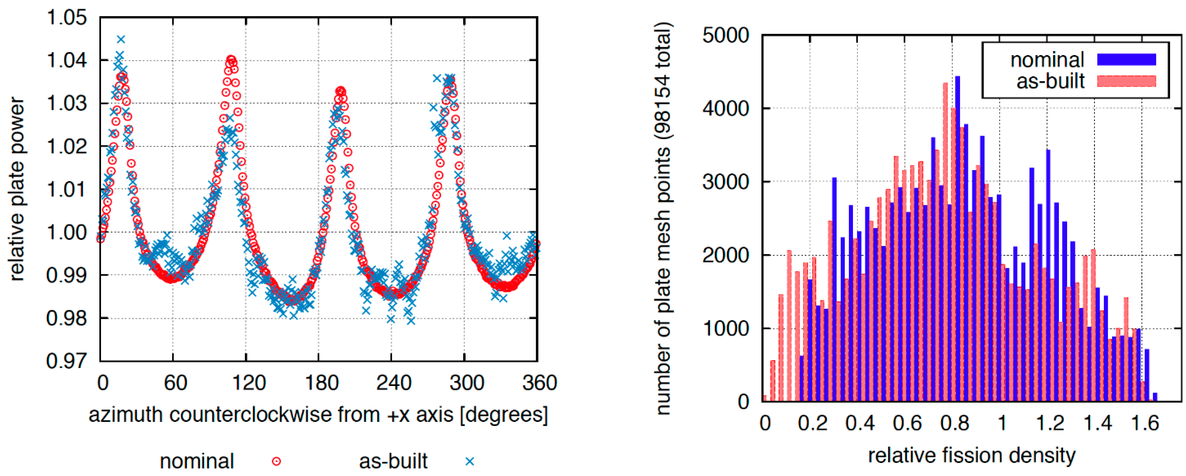
The change in the reactivity was relatively small (500 pcm) and, as expected, due to the underloading (relative to as-designed) of fuel plates toward the radial and axial edges of the plates. Replicating the as-designed fuel plates throughout the OFE yielded a smooth, well-behaved plate power distribution that was impacted by the features in the control element and reflector regions (Figure 5): the plate power recovered in azimuthal locations adjacent to the four gaps between the absorbers within the control elements. Incorporating as-built data showed significant deviations from this smooth shape, although the peak powers were nearly bounded by those of the as-deigned model (Figure 5). Localized impacts of incorporating the as-built data showed reduced peak relative power densities (Figure 5), again due to the underloading at the radial edges of the core.
5. Discussion
The programmatic generation of the explicit fuel plate models developed under the LEU Conversion Program streamlined the generation of these models and incorporation of the as-built data. The capability of ORNL-TN in generating the geometry for a very lengthy MCNP model and the scalability of Shift were also critical in generating tightly converged results within tens of hours of real-time. The resulting as-built fission density distributions were bounded by current safety factors incorporated into safety analyses, supporting the current approach for reactor operations. Local impacts from incorporating the as-built data would have little impact relative to using the as-designed fuel plates. While this level of fidelity has less use for normal operations, the capability to incorporate as-built data in models provides for the analysis of manufacturing anomalies or nonconforming components.
The MCNP model described herein is the largest and most detailed model of HFIR. To the author’s knowledge, this is the largest Shift simulation (i.e., in terms of number of cells in the model and number of cell tallies) ever performed.
Author Contributions
Conceptualization, B.R.B., D.C. and T.M.E.; methodology, B.R.B., D.C., G.G.D.; software, T.M.E., S.C.W., S.W.M.; validation, C.R.D. formal analysis, B.R.B., C.R.D., D.C.; writing—original draft preparation, B.R.B.; visualization, G.G.D., S.C.W. All authors have read and agreed to the published version of the manuscript.
Funding
This work was supported by the ORNL Research Reactors Division. This research used resources of the Oak Ridge Leadership Computing Facility at the Oak Ridge National Laboratory, which is supported by the Office of Science of the US Department of Energy under Contract No. DE-AC05-00OR22725.
Conflicts of Interest
The authors declare no conflict of interest.
References
- Cheverton, R.D.; Sims, T.M. HFIR Core Nuclear Design; ORNL-4621; Oak Ridge National Laboratory: Oak Ridge, TN, USA, 1971. [Google Scholar]
- Chandler, D.; Betzler, B.; Cook, D.; Ilas, G.; Renfro, D. Neutronic and thermal-hydraulic feasibility studies for high flux isotope reactor conversion to low-enriched uranium silicide dispersion fuel. Ann. Nucl. Energy 2019, 130, 277–292. [Google Scholar] [CrossRef]
- Chandler, D.; Betzler, B.R.; Davidson, E.E.; Ilas, G. Modeling and Simulation of a High Flux Isotope Reactor Representative Core Model for Updated Performance and Safety Basis Assessments. Nucl. Eng. Des. 2020, 366, 110752. [Google Scholar] [CrossRef]
- Pandya, T.M.; Johnson, S.R.; Evans, T.M.; Davidson, G.G.; Hamilton, S.P.; Godfrey, A.T. Implementation, capabilities, and benchmarking of shift, a massively parallel Monte Carlo radiation transport code. J. Comput. Phys. 2016, 308, 239–272. [Google Scholar] [CrossRef] [Green Version]
- Davidson, G.G.; Pandya, T.M.; Johnson, S.R.; Evans, T.M.; Isotalo, A.E.; Gentry, C.A.; Wieselquist, W.A. Nuclide depletion capabilities in the shift Monte Carlo code. Ann. Nucl. Energy 2018, 114, 259–276. [Google Scholar] [CrossRef]
- Pandya, T.M.; Johnson, S.R.; Davidson, G.G.; Evans, T.M.; Hamilton, S.P. Shift: A massively parallel monte carlo radiation transport package. In Proceedings of the M&C 2015, Nashville, TN, USA, 19–23 April 2015. [Google Scholar]
- Betzler, B.R.; Ade, B.; Chandler, D.; Ilas, G.; Sunny, E. Optimization of depletion modeling and simulation for the high flux isotope reactor. In Proceedings of the ANS Mathematics & Computation Topical Meeting, Nashville, TN, USA, 19–23 April 2015. [Google Scholar]
- X-5 Monte Carlo Team. MCNP—A General N-Particle Transport Code; Version 5; LA-UR-03-1987; Los Alamos National Laboratory: Los Alamos, NM, USA, 2003.
- Mosher, S.W.; Wilson, S.C. Algorithmic Improvements to MCNP5 for High-Resolution Fusion Neutronics Analyses. Fusion Sci. Technol. 2018, 74, 263–276. [Google Scholar] [CrossRef]
- Rearden, B.T.; Jessee, M.A. (Eds.) SCALE Code System; Version 6.2; ORNL/TM-2005/39; Oak Ridge National Laboratory: Oak Ridge, TN, USA, 2016; Available from Radiation Safety Information Computational Center at Oak Ridge National Laboratory as CCC-834. [Google Scholar]
- Betzler, B.R.; Chandler, D.; Davidson, E.E.; Ilas, G. Optimized Design Performance Analysis Tools for a High Flux Isotope Reactor Low-Enriched Uranium Core; Oak Ridge National Laboratory: Oak Ridge, TN, USA, 2018; Volume 119. [Google Scholar]
- Betzler, B.R.; Chandler, D.; Cook, D.H.; Davidson, E.E.; Ilas, G. High flux isotope reactor low-enriched uranium core designs and challenges. In Proceedings of the ANTPC 2018—Advances in Nuclear Nonproliferation Technology and Policy Conference, Wilmington, NC, USA, 23–27 September 2018. [Google Scholar]
- Chandler, D.; Betzler, B.R.; Ilas, G.; Cook, D.H.; Renfro, D.G. Neutronic and thermal-hydraulic feasibility studies for high flux isotope reactor conversion to low-enriched uranium U3Si2-Al fuel. In Proceedings of the PHYSOR 2018—Reactor Physics Paving the Way Towards More Efficient Systems, Cancun, Mexico, 22–26 April 2018. [Google Scholar]
- Betzler, B.R.; Chandler, D.; Cook, D.H.; Davidson, E.E.; Ilas, G. High flux isotope reactor low-enriched uranium core design optimization studies. In Proceedings of the PHYSOR 2018—Reactor Physics Paving the Way Towards More Efficient Systems, Cancun, Mexico, 22–26 April 2018. [Google Scholar]
- Betzler, B.R.; Chandler, D.; Davidson, E.E.; Ilas, G. Design Optimization Studies for a High Flux Isotope Reactor Low-Enriched Uranium Core; Oak Ridge National Laboratory: Oak Ridge, TN, USA, 2017; Volume 117. [Google Scholar]
- Betzler, B.R.; Chandler, D.; Davidson, E.E.; Ilas, G. High fidelity modeling and simulation for a high flux isotope reactor low-enriched uranium core design. Nucl. Sci. Eng. 2017, 187, 81–99. [Google Scholar] [CrossRef]
- Davidson, E.E.; Betzler, B.R.; Chandler, D.; Ilas, G. Heat deposition analysis for the high flux isotope reactor’s HEU and LEU core models. Nucl. Eng. Des. 2017, 322, 563–576. [Google Scholar] [CrossRef]
- Davidson, E.E.; Betzler, B.R.; Chandler, D.; Ilas, G. High-fidelity heat deposition analysis for the high flux isotope reactor. In Proceedings of the PHYSOR 2016—Unifying Theory and Experiments in the 21st Century, Sun Valley, ID, USA, 1–5 May 2016. [Google Scholar]
- Ilas, G.; Betzler, B.R.; Chandler, D.; Davidson, E.E. High flux isotope reactor core analysis—Challenges and recent enhancements in modeling and simulation. In Proceedings of the PHYSOR 2016—Unifying Theory and Experiments in the 21st Century, Sun Valley, ID, USA, 1–5 May 2016. [Google Scholar]
- Ilas, G.; Chandler, D.; Ade, B.J.; Sunny, E.E.; Betzler, B.R.; Pinkston, D. Modeling and Simulations for the High Flux Isotope Reactor Cycle 400; Oak Ridge National Laboratory Report ORNL/TM-2015/36; Oak Ridge National Laboratory: Oak Ridge, TN, USA, 2015. [Google Scholar]
- Bergeron, A. Review of the Oak Ridge National Laboratory Neutronic Calculations Regarding the Conversion of the High Flux Isotope Reactor to the Use of LEU Fuel; ANL/RERTR/TM-12/49; Argonne National Laboratory: Argonne, IL, USA, 2012. [Google Scholar]
- Oak Ridge Leadership Computing Facility. Titan Cray XK7; Oak Ridge Leadership Computing Facility: Oak Ridge, TN, USA, 2015.
Figure 1.
The high flux isotope reactor (HFIR) core at the axial horizontal midplane (left) and a top-down view of the HFIR core showing the curved fuel plates (right).
Figure 1.
The high flux isotope reactor (HFIR) core at the axial horizontal midplane (left) and a top-down view of the HFIR core showing the curved fuel plates (right).

Figure 2.
The highly enriched uranium (HEU) fuel meat profiles in the inner fuel element (IFE) (left) and the outer fuel element (OFE) (right).
Figure 2.
The highly enriched uranium (HEU) fuel meat profiles in the inner fuel element (IFE) (left) and the outer fuel element (OFE) (right).

Figure 3.
From left to right displayed as a function of axial height and length along the involute (s): a sample homogeneity scan (hasb), a calculated thickness profile from the scan (tasb), a mapped thickness profile from the scan (tasb MCNP), the nominal thickness profile (tnom), and homogeneity factors to apply to model the deviation from the nominal (hasb MCNP). This is for a single plate.

Figure 4.
The HFIR explicit fuel plate model with 369 unique OFE plates showing different materials and mixtures distributed throughout the OFE (left) and the relative fission density distribution within a given plate in the OFE (right).
Figure 4.
The HFIR explicit fuel plate model with 369 unique OFE plates showing different materials and mixtures distributed throughout the OFE (left) and the relative fission density distribution within a given plate in the OFE (right).

Figure 5.
Plate power distribution for the 369 fuel plates (left) and relative fission density distribution for all fuel mesh regions (right).
Figure 5.
Plate power distribution for the 369 fuel plates (left) and relative fission density distribution for all fuel mesh regions (right).


Table 1.
Shift calculation times.
| Model | Nodes (Processors per Node) | Real-Time (Hours) |
|---|---|---|
| One-plate as-designed | 1280 (16) | 1.17 |
| 369-plate as-designed | 5120 (16) | 2.67 |
| 369-plate as-built | 5120 (16) | 3.53 |
Publisher’s Note: MDPI stays neutral with regard to jurisdictional claims in published maps and institutional affiliations. |
© 2021 by the authors. Licensee MDPI, Basel, Switzerland. This article is an open access article distributed under the terms and conditions of the Creative Commons Attribution (CC BY) license (http://creativecommons.org/licenses/by/4.0/).
Share and Cite
MDPI and ACS Style
Betzler, B.R.; Chandler, D.; Evans, T.M.; Davidson, G.G.; Daily, C.R.; Wilson, S.C.; Mosher, S.W. As-Built Simulation of the High Flux Isotope Reactor. J. Nucl. Eng. 2021, 2, 28-34. https://doi.org/10.3390/jne2010003
AMA Style
Betzler BR, Chandler D, Evans TM, Davidson GG, Daily CR, Wilson SC, Mosher SW. As-Built Simulation of the High Flux Isotope Reactor. Journal of Nuclear Engineering. 2021; 2(1):28-34. https://doi.org/10.3390/jne2010003
Chicago/Turabian StyleBetzler, Benjamin R., David Chandler, Thomas M. Evans, Gregory G. Davidson, Charles R. Daily, Stephen C. Wilson, and Scott W. Mosher. 2021. "As-Built Simulation of the High Flux Isotope Reactor" Journal of Nuclear Engineering 2, no. 1: 28-34. https://doi.org/10.3390/jne2010003