
Identification of Property Boundaries Using an IFC-Based Cadastral Database


The Centre for Spatial Data Infrastructures and Land Administration, Department of Infrastructure Engineering, The University of Melbourne, Victoria 3010, Australia
*
Author to whom correspondence should be addressed.
Land 2021, 10(3), 300; https://doi.org/10.3390/land10030300
Submission received: 25 January 2021
/
Revised: 26 February 2021
/
Accepted: 12 March 2021
/
Published: 15 March 2021
(This article belongs to the Special Issue Smart Land Administration and Modern Cadastre: New Frontiers)
Abstract
:Property boundaries have a significant importance in cadaster as they define the legal extent of the ownership rights. Among 3D data models, Industry Foundation Class (IFC) provides the potential capabilities for modelling property boundaries in a 3D environment. In some jurisdictions, such as Victoria, Australia, some property boundaries are assigned to the faces of building elements which are modelled as solids in IFC. In order to retrieve these property boundaries, boundary identification analysis should be performed, and faces of building elements should be extracted. However, extracting faces of solids from an IFC file is not possible as faces of solids are not considered as a separate object-type. Therefore, this paper aims to develop a spatial query approach for the identification of property boundaries using 3D spatial operators of a database to address this problem. The viability of the developed approach is tested using an IFC-based 3D cadastral database with two real datasets and one test dataset. The proposed methodology not only supports vertical walls and horizontal roofs but can also be used for detecting boundaries in properties surrounded by complex building structures such as oblique and curved walls and roofs.
1. Introduction
Unclear boundaries can lead to costly disputes amongst interest holders, and boundary identification has a crucial function in solving these issues [1]. In order to perform boundary identification analysis, faces of the 3D legal space of the property, which are representatives of property boundaries should be extracted. Subsequently, based on the spatial relationships between the 3D legal space and the surrounding building elements, the type of boundary will be assigned to each face.
Currently, Building Information Modelling (BIM) is adopted by many countries for managing the 3D physical dimensions of buildings and modelling property boundaries in cadaster [1,2,3,4,5,6,7]. Therefore, it is more probable that land surveyors would use BIM models for the purpose of subdividing the ownership of properties [1,3]. Due to the fact that architects use different BIM software, when it comes to sharing information, an open file format such as IFC should be chosen to guarantee software independency.
In some jurisdictions, such as Victoria, Australia, some property boundaries are assigned to the faces of building elements such as walls, ceilings, and floors. For instance, an “Interior” boundary for a wall is defined by the interior face of the wall, an “Exterior” boundary is defined based on the exterior face of the wall, “Median” boundary is defined based on the midline between the faces of the wall, and an “Other” boundary is defined based on a line (except midline) between two faces of the wall [8]. IfcSpace element, which represents a bounded volume can be used for modelling 3D legal spaces, and its faces can represent the property boundaries [4,9].
As mentioned before, for performing boundary identification analysis, surface-level queries are needed. However, by using IFC files, surface-level queries are not possible. This stems from the fact that building elements are modelled as solids in IFC and, extracting faces of solids from an IFC file is impossible as faces of solids are not considered as a separate object-type. Therefore, they do not have a specific GlobalId (unique identifier) and cannot be extracted from the IFC file. Furthermore, according to Barzegar et al. [10], after registration of a property in the cadastral system, the data should be stored in a database. Therefore, for solving potential boundary disputes after registration of the property, a database approach for retrieving property boundaries is needed.
This study aims to provide a general analytical approach for boundary identification analysis using an IFC-based 3D cadastral database proposed by Barzegar et al. [10] to solve the issue regarding the use of IFC files for spatial analysis. This database has been designed based on the analysis requirements of cadaster and stores both physical (e.g., wall, roof, and floor) and legal (e.g., legal space, and legal zones) data. In a 3D spatial database, building elements can be modelled using polyhedral surface geometry; therefore, extracting faces of objects is feasible. Consequently, boundary identification analysis which consists of several object and surface-level queries can be performed. The developed analytical approach can differentiate among different types of property boundaries and can support both complex (surrounded by oblique and curved building structures) and simple (surrounded by horizontal and vertical building structures) legal spaces.
This paper is structured as follows. In Section 2 the related work for boundary identification analysis and spatial analysis using IFC-based 3D spatial databases are investigated to identify research gaps. Section 3 presents a methodology for boundary identification analysis using a 3D cadastral database and explains how the type of boundary is determined for each building element. In Section 4 the proposed methodology is implemented using SQL queries, and in Section 5 the results are provided. Following that, Section 6 discusses the challenges and limitations of the proposed methodology, and Section 7 concludes the paper.
2. Related work
2.1. Boundary Identification Analysis
The identification of property boundaries in a 3D environment is a new topic that has been investigated in several studies. For instance, Barzegar et al. [1] used an extension of the BIM model for land administration proposed by Atazadeh et al. [6] for the identification of different types of property boundaries. In order to access legal spaces in the 3D environment, they extruded the created footprint area of property boundaries. Moreover, they used the ray projection method alongside the topological relationships between legal space and physical elements (walls, roofs, ceilings) to differentiate between different types of boundaries. This study has been implemented using the Revit API [11]; therefore, the proposed methodology is limited to Revit files. Moreover, in the proposed methodology, complex structures such as curved and oblique walls and roofs have not been considered in the analysis and walls should be vertical (the footprint of the uppermost face of the wall should be coincident with the footprint of the lowermost face of the wall) and roofs should be horizontal.
In another study, Atazadeh et al. [7] used JSON queries of BIMViews to access BIMServer to perform some queries for retrieving legal data inside multi-story buildings using IFC files. These queries include identifying legal spaces related to private or common properties, retrieving building elements that bound a legal space and finding adjacent legal spaces at a specific building element. The queries in this paper can just retrieve the building elements assigned to property boundaries and cannot differentiate among different types of property boundaries. For instance, as mentioned before, in the cadastral system of Victoria, Australia, there are four types of property boundaries, including Interior, Exterior, Median, and Other boundaries [8]. For differentiating among these four types of boundaries, spatial relationships between legal space and building elements should be checked using spatial queries. However, BIMServer does not have any 3D spatial operator for performing spatial analysis. Furthermore, since property boundaries are assigned to the faces of building elements, for extracting the property boundaries, surface-level queries are needed. However, in IFC, building elements such as walls, ceilings, and floors are modelled as solids and faces of solids cannot be extracted from an IFC file.
To sum up, the previous studies related to boundary identification analysis are either incapable of extracting property boundaries (due to the limitations of IFC files) or cannot support complex legal spaces (associated with oblique and curved boundaries).
2.2. Spatial Analysis Using IFC-Based 3D Spatial Databases
Due to the capabilities of 3D spatial databases for performing spatial analysis, IFC-based 3D spatial databases have been used widely to answer analysis requirements in different domains. These capabilities refer to supporting different topological, directional, and metric operators for performing spatial analysis. Generally, topological operators such as Overlaps, Contain, and Touch are used to query the topological relationship between two spatial objects [12]. Metric operators such as Distance, CloserThan, and FartherThan rely on the Euclidean metric defined in 3D space [13]. Directional operators such as Above, Below, and NorthOf detect directional relations between two objects and are formed by the reference frame, which assigns names or symbols to space partitions [14].
The provided spatial queries and algorithms in one domain can be altered and used for a different purpose in another domain. Therefore, investigating the provided spatial analysis methods using 3D spatial databases in other domains can provide insights regarding the capabilities of 3D spatial databases. For instance, Solihin et al. [15] defined a schema and transformation rules to bring IFC data into the Oracle database to perform more complicated queries such as spatial queries. In the presented schema, each set of federated BIM models have their own set of tables and numeric properties are converted to string values. This conversion is required to perform queries using LIKE syntax. In this paper, XBIM was used as an IFC parser [16]. This toolkit processes the IFC geometries to generate a simplified triangulated polyhedron data, which provides the source geometry for Oracle spatial database. They also used R-tree spatial indexing, and the results showed that for spatial queries, the process is not efficient enough and takes a long time. Therefore, in their next work, Solihin et al. [17] used Octree indexing to achieve a high-performance method for querying spatial relationships. They proved that by using a combination of procedures for encoding, database storage and B-tree indexing, Octree could have a better performance in comparison with R-tree. In this research, they covered both directional and topological operators; however, they found that Octree cannot answer the touch relation. In order to find touch relations, they used boundary faces and boundary relationships.
In another work, Solihin et al. [18] proposed a simplified schema for storing IFC data using extract, transform, load (ETL) processes in the PostgreSQL database. This database has been designed based on Architecture, Engineering, Construction, and Operation (AECO) industry requirements [18]. In order to check the efficiency of this database, they performed the line of sight analysis for checking the hospital designs. In the design of hospitals, all patient rooms should be visible from the nurse station. Therefore, using a rule checking process, they tested the visibility of nurse stations by computing the shortest path between patient rooms and nurse station.
Khalili and Chua [19] also proposed a graph data model for storing topological relationships between building elements in an IFC model and stored this model in a relational database. In order to showcase the capabilities of this database, they performed two spatial analyses using C# coding including finding the shortest path from a targeted room to the exit for emergency response analysis and checking the connectivity of building elements with the purpose of grouping precast elements for prefabricated buildings to minimize the total number of components and reducing the production, transportation, and installation cost.
Although PostGIS and Oracle Spatial are the most popular 3D spatial databases, in some studies, other 3D spatial databases have been used. For instance, Lee et al. [20] stored IFC data in the CUBRID database (https://www.cubrid.org/cubrid, accessed on 15 March 2021) based on both an object-relational approach and a relational approach and compared their performance; however, they found that using an object-relational approach leads to better query performance. They only tested attribute queries, not spatial queries. He et al. [21] developed a plugin for Revit software to build a residential plan from standard-unit and then stored this plan using IFC format in a relational database. Following that, they examined the similarity between standard-units in order to collect all the similar standard-units to one standard-unit (a residential design template). To do so, they considered criteria such asroom-type similarity, room-size similarity, accessibility similarity, and adjacency similarity as a similarity vector. They, then calculated the similarity using vector distance which means the farther their distance is, the less their similarity is.
In another study, Ismail et al. [22] stored IFC data in a Neo4j graph database and used Cypher queries to extract knowledge from the database. The queries include retrieving spaces which are larger than a given area value, and spaces with more than three doors and retrieving emergency routes on the first floor of a building. Queries in this paper are not spatial queries, and the required information has been retrieved using IFC attributes stored in the database. Marmo et al. [23] created an SQLite database to support building performance assessment and maintenance management by integrating a facility management system and BIM technology. The SQL queries tested in this paper include retrieving data about corrective maintenance tasks and retrieving data about planned maintenance tasks. In both queries, no spatial function has been used.
To sum up, all the reviewed papers stored IFC data in a 3D spatial database; however, they designed the database based on the analysis requirements of a specific domain such as the AEC industry. Consequently, they did not consider legal aspects in their proposed databases. For instance, Room element in the BIM model is exported as IfcSpace and stored in the database. However, the created IfcSpace from Room element cannot be used as a representative of legal space since by default, this element is constructed using the interior faces of building elements bounding the Room. Therefore, the faces of IfcSpace in the proposed databases do not show the legal boundaries and cannot be used for boundary identification analysis.
Furthermore, no spatial query related to 3D cadaster has been found. There was just one paper [18] in which authors provided an example related to checking setback distance requirements for residential buildings facing a specific category of roads. The setback distance should be calculated based on the distance to the boundary edges of the building. However, in this paper, no implementation has been provided for this application. In general, since most of the studies have used the combination of 3D topological and metric operators to answer their analysis requirements, their methodology can provide some ideas to perform boundary identification analysis in the 3D cadastral domain. For instance, it can be found that current 3D spatial databases do not fully support 3D topological relationships (e.g., touch, and contains) [24,25]. Therefore, for checking some of the 3D topological relationships, a combination of 3D intersection and some rules should be used. In the next section, by considering the capabilities of current 3D spatial databases, a methodology for boundary identification analysis will be provided.
3. A Methodology for Boundary Identification Analysis Using a 3D Cadastral Database
As mentioned in the introduction, there are four different types of property boundaries in the cadastral system of Victoria, including Interior, Exterior, Median, and Other boundaries. These boundaries can be associated with walls, roofs, and floors. In case of floors, the boundary is generally a horizontal boundary based on strength and stability reasons in construction. However, in the case of walls and roofs, different shapes can be used. In most buildings, walls are vertical, and roofs are horizontal, but in some buildings, oblique and curved walls and roofs can also be found. In this paper, “roof” refers to the uppermost part of a property, and in an architectural context, it can also be “ceiling” and “roof slab”. In addition, “floor” refers to the lowermost part of a property, and it can also be a “floor slab”. Therefore, in the database, Roof table stores roofs, ceilings and roof slabs, and Floor table stores both floors and floor slabs. More information can be found in [10].
Figure 1 shows the proposed methodology for boundary identification analysis by considering both complex and non-complex building elements. This process starts by extracting faces of legal space and storing them in the Face table. However, in case of complex building elements (oblique, shed, gable, etc.) and curved roofs and oblique and curved walls), as shown in Figure 2, after extracting the faces of legal space; for instance, the associated face to the complex roof breaks down to several small faces. Therefore, these small faces should be collected and converted to one single geometry which is associated with the roof. In the next step, the created geometry should be stored in the Face table, and the small faces should be deleted. In order to avoid repetition of the process, the GlobalID of the complex building element is also assigned to the new face to be able to identify this face in the database effortlessly. Subsequently, this GlobalID is used for assigning the type of boundary.
It is noteworthy to mention that each property has only one floor and one roof. However, a property is surrounded by several boundary walls (walls associated with legal boundaries). Therefore, for walls, a loop should be used to be able to assign the type of boundary to all boundary walls. In the following subsections, the proposed methodology for identifying the associated property boundaries to floors, roofs, and walls will be explained in detail.
3.1. Identifying the Associated Property Boundaries to Floor (Horizontal)
For identifying property boundaries associated with the floor element, the methodology in Figure 3 is used. First faces of legal space are extracted and stored in the Face table. Then, using the intersection of legal space with floor elements, the associated floor element to the legal space is identified (boundary floor). In order to assign the type of boundary to the lowermost face of legal space (associated with the floor), the thickness of intersection between the floor and legal space (m3), and thickness of floor (m1) are used. Since these thicknesses are alongside z-direction, (Zmax − Zmin) can be used for achieving thickness. There is no need to calculate m1, and it can be retrieved from IFC (Industry Foundation Class) data and stored as Thickness attribute for each floor in the database. Since each property (legal space) has only one floor and it is always horizontal, for an Exterior boundary m3 is equal to m1, for a Median boundary m3 is equal to m1/2, and for an Interior boundary m3 is equal to zero. Figure 4 shows a Median boundary for the floor element as an example. The lowermost face of the legal space can be identified using two rules: having the minimum of Zmax among all faces and Zmax − Zmin = 0. Therefore, first, the Exterior and Median boundary types are checked, and if the face still has a null value for the boundary type attribute, Interior boundary type is assigned to the lowermost face of legal space.
3.2. Identifying the Associated Property Boundaries with Roofs (Horizontal, Oblique (Shed, and Gable), Curved)
Due to the fact that oblique and curved roofs are complicated structures, in order to use them for spatial analysis in the database, 3D bounding box which is a 3D dimensional enclosing box of geometry should be used. Therefore, for differentiating between different types of property boundaries, the thickness of intersection between 3D bounding box of legal space and 3D bounding box of roof is used.
As shown in Figure 5, for an oblique roof (gable roof as an example), if m1 is considered as roof thickness, m2 as the thickness of 3D bounding box of roof and m3 as the thickness of intersection between 3D bounding box of roof and 3D bounding box of legal space, for Exterior boundaries, m3 = m2, for Interior boundaries, m3 ≈ (m2 − m1), and for Median boundaries, m3 ≈ (m2 − (m1/2)). The same rules can be applied for a curved roof. Figure 6 shows a curved roof associated with an Interior boundary.
It is noteworthy that for Interior and Median boundaries, the rules are not defined exactly as m3 = (m2 − m1) and m3 = (m2 − (m1/2)) since as shown in Figure 7, m1 is not the real roof thickness, and it is slightly bigger than the real roof thickness. Therefore, in case of oblique roofs, m3 will have slightly lower values for Median and Interior boundaries.
By considering the difference between m1 and real roof thickness, the following rules are used to differentiate between three types of boundaries:
Exterior: m3 = m2
Median: m2 > m3 ≥ (m2 − (m1/2))
Interior: (m2 − m1) ≤ m3 < (m2 − (m1/2))
In order to assign the type of boundary to each face of legal space, since in the previous subsection, faces of legal space have been stored in the Face table, there is no need to repeat this process again. However, in case of complex roofs (oblique, shed, gable, etc.) and curved, as mentioned before, after extracting the faces of legal space, the associated face to the roof breaks down to several small faces. Therefore, these small faces should be collected and converted to one single geometry which is associated with the roof. To do so, the process in Figure 8 is used.
Therefore, first, using the intersection of roofs with the legal space, the boundary roof (roof element associated with the legal space) is detected, and it will be stored in the Boundary table (this table is only used for storing boundary elements and using them in the next steps of analysis and after identifying the type of boundary for the boundary element, boundary element is then removed from the table). In the next step, the ratio of (volume of intersection between 3D bounding box of the roof and 3D bounding box of each face of legal space)/(volume of the 3D bounding box of the face of legal space) is used for collecting the small faces associated with the roof element. The reason for using this ratio is that for a roof which is associated with an Interior boundary, the roof will have intersection with both small faces that create the real face, and other faces with joint edges to the roof. However, faces with joint edges are boundary faces associated with other building elements. Therefore, using the defined ratio, only faces that their 3D bounding box has more than 90% overlap with the 3D bounding box of roof element are collected. As such, a single geometry is created using these small faces and stored in the Face table, and the small faces are deleted from the Face table. Moreover, in order to identify the created geometry (associated face with roof) in the Face table and avoid repetition of this process in the next steps of analysis, GlobalID of roof element is also assigned to its related face of legal space in the Face table.
It should be noted that for vertical and horizontal faces of legal space, the volume of the bounding box is zero, and they are not associated with any complex building element. Therefore, for avoiding the zero value at the bottom of the ratio and simplifying the process, only non-horizontal and non-vertical faces of legal space are considered in the procedure of Figure 8.
For assigning the type of boundary to each face of legal space, the methodology in Figure 9 is used. Therefore, the thickness of intersection between 3D bounding box of the roof and 3D bounding box of legal space (m3) and thickness of 3D bounding box of roof (m2) should be calculated. Since these thicknesses are alongside z-direction, (Zmax − Zmin) can be used for achieving thickness. There is no need to calculate m1, and it can be retrieved from IFC data and stored as Thickness attribute for each roof in the database.
After calculating m2 and m3 and retrieving m1, in order to identify the associated face with a complex roof, the GlobalID of the roof which has been assigned to the face of legal space in the previous step is used. Therefore, using the identified rules in Figure 6 for differentiating among three types of boundaries, the type of boundary is assigned to the face with the same GlobalID as the complex roof. In addition, the roof element is also deleted from the Boundary table to use the Boundary table in the next subsection for identifying boundaries associated with walls. In the case of a non-complex roof (horizontal roof), the type of boundary will be assigned to the uppermost face of legal space. The uppermost face of legal space can be retrieved using two rules: having the maximum of Zmax among all faces and Zmax − Zmin = 0.
Since a horizontal roof has the same characteristics as a floor, the identified rule set for differentiating among different types of boundaries associated with the floor can also be used for a horizontal roof. It is noteworthy to mention that for a horizontal roof, the determined rules in Figure 6 will be equal to the identified rules for the floor in the previous subsection as below:
Therefore, to avoid repetition of the m3 calculation process, the ruleset of complex roofs can also be used for horizontal roofs.
3.3. Identifying the Associated Property Boundaries with Walls (Vertical, Oblique, and Curved)
In the case of walls, the identified rules for roofs can also be applied. As shown in Figure 10, for an oblique wall, if m1 is considered as wall thickness, m2 as the thickness of 3D bounding box of wall, and m3 as the thickness of intersection between 3D bounding box of the wall and 3D bounding box of legal space, for Exterior boundaries, m3 = m2, for Interior boundaries, m3 ≈ (m2 − m1), and for Median boundaries, m3 ≈ (m2 − (m1/2)). The same rules can apply for a curved and vertical wall. Figure 11 shows a curved wall associated with a Median boundary, and Figure 12 shows a vertical wall associated with an Exterior boundary.
It is noteworthy that similar to complex roofs, rules are not defined exactly as (m2 − m1) and (m2 − (m1/2)) since as shown in Figure 13, m1 is not the real wall thickness, and it is slightly bigger than the real wall thickness. Therefore, in the case of oblique walls, m3 will have slightly lower values for Median and Interior boundaries. Therefore, by considering the difference between m1 and the real wall thickness, the defined intervals in the previous subsection for roofs are also used for walls.
In order to detect different types of property boundaries associated with wall elements, first, the boundary walls are detected using the intersection of faces of legal space with a null value for boundary_type attribute (other faces have a value for boundary_type attribute since they are associated with floor and roof elements and their boundary type have been assigned in the previous subsections). Due to the fact that associated faces of legal space with roof and floor also have intersection with internal walls, if these faces are considered in the analysis, the result of the intersection between walls and legal space will be both internal (located inside of legal space) and boundary walls (Figure 14). Therefore, for detecting boundary walls, only associated faces of legal space with walls should be considered, and the legal space itself cannot be used.
After finding boundary walls, the same procedure as the roof procedure should be applied to convert the small faces related to each complex wall to a single geometry (Figure 15). Therefore, by considering the ratio of (volume of intersection between 3D bounding box of the wall and 3D bounding box of a non-horizontal and non-vertical face of legal space)/(volume of the 3D bounding box of the non-horizontal and non-vertical face of legal space), small faces associated with the wall element are collected. In the next step, using this ratio, only faces that the 3D bounding box has more than 90% overlap with the 3D bounding box of roof element are collected. Subsequently, a single geometry is created using these small faces and stored in the Face table, and the small faces are deleted from the Face table. Moreover, in order to identify the created geometry (associated face with the wall) in the Face table and avoid repetition of this process in the next steps of analysis, GlobalID of the wall element is also assigned to its related face of legal space in the Face table. Since a property might be surrounded by several complex walls, this process should be performed in a loop. Moreover, this process is also done for only the complex walls which surround a complex legal space.
For assigning the type of boundary to the faces associated with walls, the methodology in Figure 16 is used.
As mentioned before, the thickness of intersection between 3D bounding box of the wall and 3D bounding box of legal space (m3), the thickness of 3D bounding box of the wall (m2) and thickness of the wall (m1) are used to find the associated property boundary to the wall. Depending on the orientation of the wall, (Xmax − Xmin) or (Ymax − Ymin) can be used for computing the thickness alongside the XY axis. For each wall one shows the thickness and another one shows the length of the 3D bounding box. Since the thickness of the wall is always less than the length of the wall (same rule can be considered for the 3D bounding box), Min ((Xmax − Xmin), (Ymax − Ymin)) provides the thickness. Therefore, Min ((Xmax − Xmin), (Ymax − Ymin)) 3D bounding box of wall and Min ((Xmax − Xmin), (Ymax − Ymin)) intersection between 3D bounding box of the wall and 3D bounding box of legal space are used for computing m3 and m2. There is no need to calculate m1 since it can be retrieved from IFC data and stored as Thickness attribute for each wall in the database.
It should be noted that usually a property has more than four walls and most of the walls are vertical. In addition, if for all properties 3D bounding box of legal space is used, due to the fact that 3D bounding box is only a simple cubic representation, some errors may occur (Figure 17). Therefore, for avoiding errors as much as possible, for properties with a non-complex legal space (without any oblique or curved wall), the real geometries of legal space and walls are used in the analysis and for properties with complex legal spaces, the 3D bounding box of legal space and 3D bounding box of the wall are used. It is noteworthy to mention that using the 3D bounding box is the only way to perform spatial analysis with complex structures since the PostGIS database does not recognize these structures as valid objects. Therefore, PostGIS does not let users perform accurate spatial analysis such as retrieving the geometry of the result of the intersection between two 3D objects (ST_3DIntersection) and computing volume (ST_Volume) for complex structures.
After identifying the type of boundary, using the assigned GlobalID of the complex wall to its associated face of legal space in the Face table (this GlobalID was assigned to the face after conversion to a single geometry in the previous step), the boundary type of each complex wall will be assigned to the face of legal space with the same GlobalID. For non-complex walls, the boundary type will be assigned to their closest face of legal space by computing the minimum distances between faces of legal space and the center point of the wall. After assigning Exterior and Median boundary types to surround faces of legal space, for faces with a null value for the boundary_type attribute in the Face table, Interior boundary type is assigned. For avoiding duplication in the database, the rows of Boundary table are deleted after completion of the process.
4. Implementation of the Proposed Spatial Query Approach
In order to show the viability of the proposed approach, an IFC-based 3D cadastral database is used [10]. In this database, two real datasets with multi-story buildings located in Victoria, Australia, and one test dataset which includes properties with oblique and curved structures and a property with a hole have been stored. In this process, first, the legal spaces and other legal information such as the name of the owner of each property, legal zones and restrictions of each property are added to the BIM (Building Information Modelling) models. In the next step, BIM models are georeferenced in ArcGIS Pro. The coordinate system is used in Australia is Geocentric Datum of Australia (GDA94), and Melbourne is located in Zone 55 (EPSG:28355). Noteworthy to mention that, georeferencing is a mandatory step since when for instance the geometries of roof elements from different files are stored in the geometry column of the Roof table in the database, all should be in the same coordinate system and have the same Spatial Reference Identifier (SRID). After georeferencing, the data is exported to IFC. Figure 18 shows the two buildings in the first real datasets, and Figure 19 shows the building in the second real dataset. Moreover, Figure 20 shows the test dataset with oblique and curved structures and a hole in Solibri AnyWhere model viewer.
In the next step, IFC data validation and data cleaning are performed to prepare clean IFC data. Following that, the required pertinent IFC data elements to cadaster are stored in the PostGIS database using the FME software. For removing the errors that may occur in the conversion process (solid geometry of IFC to the polyhedral surface geometry of the PostGIS data), PostGIS data validation and cleaning are performed to prepare clean data for the analysis. For more information about this database, see [10]. Table 1 shows the required tables for boundary identification analysis in this database. The GlobalID attribute refers to IFC GlobalID for each element, and Building attribute refers to the GlobalID of the building in which the element is located. Moreover, the BuildingStorey attribute refers to the instance name of the building story in which the element is located. The Instance Name attribute is a label that is assigned to each instance of a collection in order to be able to identify the instance [26].
In order to be able to identify legal spaces associated with complex building structures in the database, Complex attribute is defined. Therefore, complex building elements have True value for Complex attribute and non-complex building elements have False value. Furthermore, for retrieving the thickness of building elements, the Reference attribute in the IFC common property sets is used. Since in the proposed methodologies several loops are needed, SQL codes are implemented in Python using Psycopg2 API.
4.1. Boundary Associated with Floor
For retrieving the boundary associated with floor, the methodology in Figure 3 is used, and Floor and LegalSpace tables should be considered.
- 1-
- The first step is extracting faces of legal space. To do so, faces are extracted using St_GemetryN function and stored in the Face table. This table has four columns, including face_number, geom, boundary_type, and boundary_globalid. The boundary_globalid attribute will be used in the next subsections for assigning the GlobalID of associated complex boundary roof or wall to each face, but since the floor cannot be a complex structure, this column is not used in this subsection. The SQL statements of Appendix A.1 are used to create the Face table and storing faces in this table.
- 2-
- The second step is retrieving the boundary floor (Appendix A.2-(table_1, table_2)). Therefore, the intersection of legal space with floors is being checked using ST_3DIntersects function to find the boundary floor. In order to expedite the process of detecting the boundary floor, only the floors which are located in the same building as the legal space are considered (using the building attribute of tables).
- 3-
- The third step is computing m3 (thickness of intersection between 3D bounding box of the floor and 3D bounding box of legal space) using 3DIntersection function and retrieving m1 to be able to identify the type of boundary associated with the floor (Appendix A.2-(table_3)).
- 4-
- Using the values of m1 and m2, and the defined rule set in Section 3.1, the type of boundary associated with the floor is identified. In the next step, the type of boundary should be assigned to the lowermost face of legal space associated with the floor. In order to assign the type of boundary to the lowermost face, the boundary_type attribute in the Face table should be updated three times since, in the proposed method, three types of boundaries are detected. However, due to the fact that in a SQL code with several With clauses, the order in which the updates actually happen is unpredictable, defining three updates in With clauses is not an efficient way for assigning the boundary type [27]. To overcome this problem and avoid repeating the execution of a SQL statement with high computation cost (3DIntersection) and expedite the process, the result of SQL statements of Appendix A.2 is stored in a Materialized View. Following that, first, Exterior (Appendix A.3) and Median (Appendix A.4) boundary types are being checked, and then if the face still has a null value for boundary_type attribute, the Interior boundary type is assigned to the face (Appendix A.5). To avoid duplication of data, after assigning the type of boundary to the face associated with floor, the created Materialized View is also removed using Drop statement.
4.2. Boundaries Associated with Roofs
For retrieving the boundaries associated with roofs, the methodologies in Figure 8 and Figure 9 are used, and Roof and LegalSpace tables should be considered. The procedure is as follows:
- 1-
- First, the Boundary table that stores boundary elements to be utilized in the next steps of analysis should be created. This table has four columns which store the geometry of the boundary element, its GlobalID and the values for Complex and Thickness attributes of the element. Then, the boundary roof should be retrieved using the intersection of the 3D bounding box of legal space and 3D bounding box of roofs. To expedite the process, only roofs which are located in the same building as legal space are considered. Boundary roof is also stored in the Boundary table for using in the next steps (Appendix B.1).
- 2-
- After retrieving boundary roof, for a complex roof (with True value for Complex attribute), the ratio of (volume of intersection between 3D bounding box of the roof and 3D bounding box of each face of legal space)/(volume of the 3D bounding box of the face of legal space) is used to collect the small faces associated with this roof and convert them to a single geometry using ST_Collect function (Appendix B.2). After converting small faces to a single geometry, the created geometry is then inserted to the Face table, and the small faces are deleted. Since Insert and Delete are used in data manipulation statements, to avoid repeating the process, after collecting associated faces with the complex roof, they are stored in a Materialized View. Therefore, using the Materialized View, the required Insert and Delete statements are performed. To avoid duplication of data, after finishing the process, the created Materialized View is removed using the Drop statement.
- 3-
- For finding the type of boundary for the boundary roof, the thickness of intersection between 3D bounding box of the roof and 3D bounding box of legal space (m3) and thickness of 3D bounding box of roof (m2) should be calculated (Appendix B.3). Moreover, the results are stored in a Materialized View to avoid repetition of the process in the next steps. For a non-complex roof, the type of boundary will be assigned to the uppermost face of legal space. Appendix B.4, Appendix B.5 and Appendix B.6 show the required SQL codes for assigning Exterior, Median and Interior boundary types to the associated face with a non-complex roof. For a complex roof, using the GlobalID of the roof in the Boundary table, the type of boundary will be assigned to the face of legal space. Appendix B.7, Appendix B.8, and Appendix B.9 show the required SQL codes for assigning Exterior, Median, and Interior boundary types to the associated face with a non-complex roof.
- 4-
- After assigning the type of boundary to the associated face with roof, the related row in the Boundary table to the roof element and the created Materialized View in the previous steps will be deleted (Appendix B.10).
4.3. Boundaries Associated with Walls
For retrieving the property boundaries associated with walls, Wall_Exterior, Wall_Interior, and LegalSpace tables should be considered. The methodology is as follows (Figure 15 and Figure 16):
- 1-
- The first step is retrieving boundary walls. Therefore, the intersection of faces of legal space with walls is being checked using ST_3DIntersects function. For detecting boundary walls, only surrounding faces of LegalSpace should be considered. Since the type of boundary has been assigned to the faces of legal space associated with floor and roof in previous steps, at this stage, only the faces associated with walls have a null value for boundary_type attribute. Therefore, using this criterion, the faces associated with walls can be retrieved (temporary table_1 in Appendix C.1).In order to expedite the process of detecting boundary walls, only the walls which are located in the same building and building storey as the legal space are considered (using the Building and BuildingStorey attributes of tables). After finding all walls on the same storey and building, they are all populated in a temporary table (table_5 in Appendix C.1) using Union All operator. In the next step, the intersected walls with faces of legal space will be retrieved (temporary table_6 in Appendix C.1) and stored in the Boundary table. Moreover, complex walls are also stored in the Complex table (a new table, Appendix C.2).
- 2-
- After retrieving boundary walls, for a complex wall (with True value for Complex attribute), the ratio of (volume of intersection between 3D bounding box of the wall and 3D bounding box of each face of legal space) / (volume of the 3D bounding box of the face of legal space) is used to collect the small faces of legal space associated with this wall and storing the results in a Materialized View. Then, the small faces are converted to a single geometry using ST_Collect function, and the new geometry and the GlobalID of its associated complex wall are stored in the Face table. In the next step, small faces are deleted from the Face table and Materialized View is also removed. This process repeats until all complex walls are checked (Appendix C.3).
- 3-
- In order to differentiate between different types of property boundaries, for a non-complex legal space, the thickness of intersection between the legal space and wall is used. However, for a complex legal space, the thickness of intersection between 3D bounding box of legal space and 3D bounding box of the wall is used.For finding the type of boundary for each boundary wall, the thickness of intersection between 3D bounding box of the wall and 3D bounding box of legal space (m3) and thickness of 3D bounding box of the wall (m2) should be calculated (Appendix C.4 (non-complex legal space), Appendix C.5 (complex legal space)). For a non-complex wall, the GlobalID of the associated wall with the face is unknown. Therefore, for instance, in case of an Exterior boundary, by computing the distance from each face of the legal space to the center point of walls associated with Exterior boundaries, the Exterior boundary type will be assigned to the closest face of each wall in the Face table (Appendix C.6 (Exterior), Appendix C.7 (Median), Appendix C.8 (Interior)). However, since in step 2 (Appendix C.3), the GlobalID of the wall has been assigned to its associated face of legal space (collection of small faces that have been stored as a single geometry in the Face table), for a complex wall, using the stored GlobalID of the wall in the Complex table, the type of boundary will be assigned to the face of legal space (Appendix C.9 (Exterior), Appendix C.10 (Median), and Appendix C.11 (Interior)). It should be noted that a complex legal space might be surrounded by both complex and non-complex (vertical) walls. Therefore, for a complex legal space, both mentioned procedures for assigning the type of boundary to complex and non-complex walls should be used.Since in the previous steps, the type of boundary has been assigned for faces of legal space associated with floor and roof, only the faces of legal space associated with walls have remained with a null value for boundary_type attribute in the Face table. Therefore, first, the Exterior and Median boundary types are assigned to faces, and then for those faces with a null value for boundary_type attribute, the Interior boundary type is assigned.
- 4-
- To avoid redundancy in the database, the rows in Boundary and Complex tables and the created Materialized Views will be deleted after completion of the process.
5. Results
Due to the fact that the PostGIS database cannot visualize 3D objects, for visualizing the results, FME software has been employed. Therefore, if the 2D plan of two properties would be similar to Figure 21 (located in the real dataset1, Figure 18), the type of defined boundaries for the legal space of the lot on the left side of Figure 21 (Globalid: 3DIM_BZAL3S95wtC0WrsWI) can be assigned to the faces of legal space as shown in Figure 22 and Figure 23.
Furthermore, the type of property boundaries for the legal space of the lot on the right side of Figure 21 (Globalid: 0_rhK5ycT19Ow$HhyTPffK) can be assigned to the faces of legal space as shown in Figure 24 and Figure 25 for boundaries associated with walls and Figure 26 for a boundary associated with roof.
Furthermore, Figure 27 shows an Exterior boundary for one of the shapes in the test dataset with oblique walls (the one without the roof in Figure 20) and Figure 28 shows the result of analysis for a test shape with a curved wall in which the curved wall is associated with a Median boundary. Moreover, Figure 29 shows the result of analysis for a legal space with a hole in the test dataset and one of its Exterior boundaries associated with the roof.
In order to show property boundaries in a more tangible way, different colors can be defined for each type of property boundaries in FME software, as shown in Figure 30.
6. Discussion
In the cadastral system, the legal extent of the ownership of properties is defined using property boundaries. These property boundaries are mostly assigned to the faces of building elements including walls, floors, and roofs. By moving towards 3D cadastral systems, the IFC (Industry Foundation Class) data model is increasingly being adopted for modelling property boundaries. In order to retrieve property boundaries from an IFC model, the faces of 3D legal space of each property should be extracted, and the type of boundary should be assigned to each face based on the spatial relationships between 3D legal space and the surrounding building elements. However, since 3D legal spaces are modelled as solids in IFC, extracting faces of legal space from an IFC model is impossible. Therefore, in this study, a method for boundary identification analysis using an IFC-based 3D cadastral database was proposed to solve this problem. In the utilized database, objects were modelled as polyhedral surfaces. Therefore, faces of objects were extracted and using the spatial operators of the database, the type of boundary was assigned to each face of legal space. The proposed methodology not only can support simple legal spaces surrounded by vertical walls and horizontal roof but can also support complex legal spaces surrounded by oblique and curved walls and roofs.
Although some of the challenges were addressed in the proposed method, during implementation, other challenges have also been identified. The first challenge is related to faces that cannot be associated with a specific wall. As shown in Figure 31, when different types of walls have been drawn in a row, and an Exterior boundary is defined to show the legal extent for these walls, two small faces are needed to connect the boundaries of these walls. However, these small faces cannot be associated with any of these three walls since surveyors do not consider these small faces on 2D plans. Therefore, the defined Exterior boundary on the right side of the lot is considered as one line (one face of legal space) on 2D plans, but in reality, those smalls faces should also be considered.
The same problem can happen when an Exterior boundary and a Median boundary are defined in a row (Figure 32). In order to connect an Exterior boundary to a Median boundary in a BIM model, a small face is needed. This small face cannot be categorized in any category of property boundaries.
Another challenge was related to ST_Dump function. Although based on the PostGIS documents, the ST_Dump function is more efficient when compare to ST_GeometryN function [28], as when using ST_Dump function, the uppermost and lowermost faces of the object with a curved wall in the test dataset (Figure 20) could not be extracted, and the resultant geometry for these two faces were two line geometries instead of polygon geometries. However, using ST_GeometryN function, all faces of legal space were extracted correctly from the geometry of legal space.
In the proposed methodology, holes created by columns in the legal space of properties have not been considered since the properties of the utilized datasets did not have any hole caused by a column. There was only one hole in the test dataset (Figure 20) which was defined using walls. In order to detect the created boundaries by columns, columns should also be considered in the analysis. In addition, in the proposed methodology, we considered floors as horizontal objects; however, as a special case, ramped floors in car parks can also be used for defining the boundary. In this case, the proposed methodology for oblique roofs can be applied to identify boundaries associated with ramped floors.
Another special case is related to split-level apartments. Although a split-level apartment has two or more floors, the ownership of the whole apartment is the same. Therefore, there is just one legal space for the apartment, and only the lowermost floor is used for defining the legal boundary, and the other parts (slab floors or ceilings) locate inside of legal space and cannot define the legal boundary of the apartment.
One limitation of the proposed method is related to Other boundaries. Due to the difference between the real wall and roof thickness and m1, Median and Other boundaries overlap in their intervals and in some cases, they are not differentiable. These cases are related to complex structures since as shown in Figure 12, for a vertical wall, m1 is exactly equal to the wall thickness, and Median and Other boundaries are differentiable for vertical walls. Although Other boundaries are detectable for simple structures including floor, horizontal roof, and vertical walls, since they are rarely defined on subdivision plans, they were not considered in this paper.
It is noteworthy to mention that the proposed methodology requires clean data. Therefore, as mentioned in the Implementation section, in order to prepare a clean data for the analysis, performing IFC data validation and cleaning and PostGIS data validation and cleaning is mandatory. The required steps for data validation and cleaning have been explained in [10] which are based on the ePlan Protocol, the electronic plan lodgment and examination system in Australia. In addition, the correctness of the result of analysis has also been checked using the same ruleset.
In the proposed methodology, different strategies for query optimization, including partitioning of data, using Materialized Views aligned with covering indices and defining spatial index for geometry column have been used. However, for some legal spaces, the execution time was still relatively high (around five minutes). These legal spaces were related to common properties of multi-story buildings which are surrounded by many walls. Therefore, due to high computation cost of spatial operators, the process of boundary identification analysis was longer compared to other legal spaces.
7. Conclusions
In this paper, a spatial query approach for the identification of property boundaries using the spatial operators of a 3D cadastral database was developed. To differentiate among different types of property boundaries, the thickness of the intersection between the legal space and building elements (walls, ceilings, and floors) was considered as a criterion. The proposed approach can detect three types of property boundaries, including Interior, Exterior, and Median boundaries. Moreover, it not only supports vertical walls and horizontal roofs, but it can also be used for detecting boundaries in properties surrounded by complex building structures such as oblique and curved walls and roofs.
In order to show the feasibility of the proposed methodology, legal boundaries of three different datasets have been identified and the correctness of boundaries have been checked using the provided validation rules in [10]. The results showed that this methodology works well with clean data. However, if data has not been cleaned properly, the errors in data can lead to errors in the result of boundary identification analysis. Therefore, data validation and cleaning are mandatory steps in the data preparation phase.
For future research, in order to represent the results in a more tangible way, the result of the analysis can be visualized in a web platform, and a query tool for boundary identification analysis can be designed on this platform. Therefore, a wide range of stakeholders can benefit from the proposed method in the management of properties and solving boundary disputes. Furthermore, the proposed methodology can be modified to be able to detect Other boundaries for complex legal spaces.
Author Contributions
Conceptualization, M.B.; methodology, M.B.; software, M.B.; validation, M.B.; formal analysis, M.B.; investigation, M.B.; resources, M.B.; data curation, M.B., B.A.; writing—original draft preparation, M.B.; writing—review and editing, M.B., A.R., M.K., and B.A.; visualization, M.B.; supervision, A.R., M.K., and B.A.; project administration, A.R.; funding ac-quisition, A.R., M.K. All authors have read and agreed to the published version of the manuscript.
Funding
This research was funded by the Australian Research Council (ARC), grant number LP160100292.
Acknowledgments
The authors acknowledge the support of project partners: Land Use Victoria, Intergovernmental Committee on Surveying and Mapping (ICSM) and City of Melbourne.
Conflicts of Interest
The authors declare no conflict of interest. The funders had no role in the design of the study; in the collection, analyses, or interpretation of data; in the writing of the manuscript, or in the decision to publish the results.
Appendix A
Appendix A.1. SQL Queries for Extracting Faces of Legal Space and Storing Them in the Face Table
Create table public."Face" (geom geometry, face_number Integer, boundary_type varchar, boundary_globalid varchar);
Insert into public."Face" (geom, face_number)
Select ST_GeometryN(geom, n), n FROM public." LegalSpace" CROSS JOIN generate_series (1,100) n
WHERE globalid = '2wfBi8$Hz16QfLtVOU_zWd' and n ≤ ST_NumGeometries(geom);
- -
- '2wfBi8$Hz16QfLtVOU_zWd' shows the GlobalID of legal space and generate_series function generates a series of integers from 1 to 100 and assigns these integers to the extracted faces of legal space (using ST_GeometryN function) as face_number. Using n ≤ ST_NumGeometries(geom) condition, only integer values smaller than the total number of faces are used.
Appendix A.2. SQL Queries for Retrieving Boundary Floor and Computing m1 and m3 and Storing the Result in a Materialized View to Use It in the Next Steps
Create Materialized View public."result_intersection" as with table_1 as (select geom as space, building from public."LegalSpace" where globalid = '2wfBi8$Hz16QfLtVOU_zWd'),
- -
- Retrieving the building in which legal space is located and the geometry of legal space
Table_2 as (select distinct b.geom as floor, b.globalid, b.thickness from table_1 a, public."Floor" b where ST_3DIntersects ((a.geom),(b.geom)) and a.building = b.building),
- -
- Retrieving the boundary floor
Table_3 as (select distinct thickness as m1, floor, (st_zmax(Box3D(st_3dintersection(Box3D(a.space), Box3D (b.floor)))) - st_zmin(Box3D (st_3dintersection(Box3D (a.space), Box3D (b.floor)))) as m3 from table_1 a, table_2 b)
Select * from table_3;
- -
- Computing m3 and retrieving m1
Appendix A.3. SQL Queries for Assigning Exterior Boundary Type to the Associated Face of Legal Space with the Floor
With table_4 as (select face_number, from public."Face" where st_zmax(Box3D(geom)) = (select min(st_zmax(Box3D(geom))) from public."Face") and st_zmax(Box3D(geom)- st_zmin(Box3D(geom) = 0),
- -
- Retrieving the lowermost face of legal space (it has the min of Zmax among all faces and zmax-zmin = 0)
Table_5 as (select floor from public."result_intersection" where m3 = m1),
- -
- Floor associated with an Exterior boundary
Table_6 as (select a.face_number, b.floor from table_4 a, table_5 b where b.floor is not null)
- -
- Retrieving the face_number of the lowermost face in case of the existence of an Exterior boundary
UPDATE public."Face" SET boundary_type = 'Exterior' WHERE face_number in (select face_number from table_6);
- -
- Assigning Exterior boundary type to the floor
Appendix A.4. SQL Queries for Assigning Median Boundary Type to the Associated Face of Legal Space with the Floor
With table_4 as (select face_number, from public."Face" where st_zmax(Box3D(geom)) = (select min(st_zmax(Box3D(geom))) from public."Face") and st_zmax(Box3D(geom)- st_zmin(Box3D(geom) = 0),
- -
- Retrieving the lowermost face of legal space (it has the min of Zmax among all faces and zmax-zmin = 0)
Table_7 as (select floor from public."result_intersection" where m3 = (m1/2))),
- -
- Floor associated with a Median boundary
Table_8 as (select a.face_number, b.floor from table_4 a, table_7 b where b.floor is not null)
- -
- Retrieving the face_number of the lowermost face in case of the existence of a Median boundary
UPDATE public."Face1" SET boundary_type = 'Median' WHERE face_number in (select face_number from table_8);
- -
- Assigning Median boundary type to the floor
Appendix A.5. SQL Query for Assigning Interior Boundary Type to the Associated Face of Legal Space with Floor
UPDATE public."Face" SET boundary_type = 'Interior' WHERE boundary_type is null and st_zmax(Box3D(geom)) = (select min(st_zmax(Box3D(geom))) from public."Face") and st_zmax(Box3D(geom)- st_zmin(Box3D(geom) = 0;
- -
- Assigning Interior boundary type to the floor
Drop Materialized View public."result_intersection";
- -
- Removing Materialized View to avoid duplication
Appendix B
Appendix B.1. SQL Query for Retrieving Boundary Roof and Storing in the Boundary Table
Create table public."Boundary" (geom geometry, complex Boolean, globalid varchar, thickness Integer);
- -
- Creating the Boundary table
Table_1 as (select geom as space, building from public."LegalSpace" where globalid = '2wfBi8$Hz16QfLtVOU_zWd'),
- -
- Retrieving the building in which legal space is located and the geometry of legal space
Table_2 as (select distinct b.geom, b.globalid, b.thickness, b.complex from table_1 a, public."Roof" b where ST_3DIntersects ((a.geom),(b.geom)) and a.building = b.building),
- -
- Retrieving boundary roof
Insert into public. "Boundary" (geom, complex, globalid, thickness) Select geom, complex, globalid, thickness from table_2;
- -
- Storing boundary roof in Boundary table
Appendix B.2. SQL Query for Collecting the Small Faces Associated with a Complex Roof and Convert Them to a Single Geometry
Create Materialized View public."result" as with table_1 as (select geom as geom1 from public."Face" where st_volume(box3d(geom)) > 0),
- -
- Considering only non-vertical and non-horizontal faces of legal space
Table_2 as (select geom, globalid from public."Boundary" where complex = True),
- -
- Checking the roof is complex or not
Table_3 as (select a.face_number, b.globalid, (st_volume(box3d(st_3dintersection(box3d(a.geom1),box3d(b.geom))))/st_volume(box3d(geom1))) as ratio from table_1 a, table_2 b where st_3Dintersects(box3d(a.geom1),box3d(b.geom)) and st_volume(box3d(geom1)) > 0) Select * from table_3;
- -
- Collecting small faces associated with a complex roof
Insert into public."Face" (geom, boundary_globalid) Select st_collect(geom1) as geom, globalid from public."result" where ratio > 0.9;
- -
- Converting small faces to a single geometry and storing the new geometry in the Face table
Delete from public."Face" where face_number in (select face_number from public."result");
- -
- Deleting small faces from Face table
Drop Materialized View public."result";
- -
- Removing Materialized View to avoid duplication
Appendix B.3. SQL Query for Computing m2, m3 and Retrieving m1 and Storing the Result in a Materialized View to Use It in the Next Steps
Create Materialized View public."result_intersection" as with table_1 as (select geom as space from public."LegalSpace" where globalid = '2wfBi8$Hz16QfLtVOU_zWd'),
- -
- Retrieving the geometry of legal space
Table_2 as (select geom as roof, globalid, complex, thickness from public."Boundary"),
- -
- Retrieving the roof from Boundary table
Table_3 as (select distinct (st_zmax(Box3D(b.roof)) - st_zmin(Box3D(b.roof)) as m2, b.thickness as m1, b.complex, b.roof, b.globalid, (st_zmax(Box3D(st_3dintersection(Box3D(a.space), Box3D (b.roof)))) - st_zmin(Box3D (st_3dintersection(Box3D (a.space), Box3D (b.roof)))) as m3 from table_1 a, table_2 b)
Select * from table_3;
- -
- Computing m2 and m3 and retrieving m1
Appendix B.4. SQL Query for Assigning Exterior Boundary Type to the Associated Face with a Non-Complex Roof
With table_4 as (select roof, complex, globalid from public."result_intersection" where m3 = m2),
- -
- Roof associated with an Exterior boundary
Table_5 as (select a.face_number from public."Face" a, table_4 b where st_zmax(Box3D(a.geom)) = (select max(st_zmax(Box3D(geom))) from public."Face") and st_zmax(Box3D(a.geom)- st_zmin(Box3D(a.geom) = 0 and b.complex = False)
- -
- Retrieving the face_number of the uppermost face of legal space (it has the max of Zmax among all faces and zmax-zmin = 0) which is associated with a non-complex roof
UPDATE public."Face" SET boundary_type = 'Exterior' WHERE face_number in (select face_number from table_5);
- -
- Assigning Exterior boundary type to the face of legal space associated with the non-complex roof
Appendix B.5. SQL Query for Assigning Median Boundary Type to the Associated Face with a Non-Complex Roof
With table_8 as (select roof, complex, globalid from public."result_intersection" where m3 ≥ (m2 − (m1/2)) and m3 < m2),
- -
- Roof associated with a Median boundary
Table_9 as (select a.face_number from public. "Face" a, table_8 b where st_zmax(Box3D(a.geom)) = (select max(st_zmax(Box3D(geom))) from public."Face") and st_zmax(Box3D(a.geom)- st_zmin(Box3D(a.geom) = 0 and b.complex = False)
- -
- Retrieving the face_number of the uppermost face of legal space (it has the max of Zmax among all faces and zmax-zmin = 0) which is associated with a non-complex roof
UPDATE public."Face" SET boundary_type = 'Median' WHERE face_number in (select face_number from table_9);
- -
- Assigning Median boundary type to the face of legal space associated with the non-complex roof
Appendix B.6. SQL Query for Assigning Interior Boundary Type to the Associated Face with a Non-Complex Roof
With table_10 as (select roof, complex, globalid from public."result_intersection" where m3 ≥ (m2 − m1) and m3 < (m2 − (m1/2))),
- -
- Roof associated with an Interior boundary
Table_11 as (select a.face_number from public."Face" a, table_10 b where st_zmax(Box3D(a.geom)) = (select max(st_zmax(Box3D(geom))) from public."Face") and st_zmax(Box3D(a.geom)-st_zmin(Box3D(a.geom) = 0 and b.complex = False)
- -
- Retrieving the face_number of the uppermost face of legal space (it has the max of Zmax among all faces and zmax-zmin = 0) which is associated with a non-complex roof
UPDATE public."Face" SET boundary_type = 'Interior' WHERE face_number in (select face_number from table_11);
- -
- Assigning Interior boundary type to the face of legal space associated with the non-complex roof
Appendix B.7. SQL Query for Assigning Exterior Boundary Type to the Associated Face with a Complex Roof
With table_4 as (select roof, complex, globalid from public. "result_intersection" where m3 = m2),
- -
- Roof associated with an Exterior boundary
UPDATE public."Face" SET boundary_type = 'Exterior' WHERE boundary_globalid in (select globalid from table_4);
- -
- Assigning Exterior boundary type to the face of legal space associated with a complex roof
Appendix B.8. SQL Query for Assigning Median Boundary Type to the Associated Face with a Complex Roof
With table_5 as (select roof, complex, globalid from public. "result_intersection" where m3 ≥ (m2 − (m1/2)) and m3 < m2),
- -
- Roof associated with a Median boundary
UPDATE public."Face" SET boundary_type = 'Median' WHERE face_number in (select face_number from table_5);
- -
- Assigning Median boundary type to the face of legal space associated with the complex roof
Appendix B.9. SQL Query for Assigning Interior Boundary Type to the Associated Face with a Complex Roof
With table_6 as (select roof, complex, globalid from public."result_intersection" where m3 ≥ (m2 − m1) and m3 < (m2 − (m1/2))),
- -
- Roof associated with an Interior boundary
UPDATE public."Face" SET boundary_type = 'Interior' WHERE face_number in (select face_number from table_6);
- -
- Assigning Interior boundary type to the face of legal space associated with the complex roof
Appendix B.10. SQL Query for Removing the Related Row in the Boundary Table to the Roof Element and the Materialized View
Delete from public."Boundary" where globalid Is Not Null;
- -
- Removing the related row in the Boundary table to the roof element
Drop Materialized View public."result_intersection";
- -
- Removing Materialized View to avoid duplication
Appendix C
Appendix C.1. SQL Query for Retrieving Boundary Walls Associated with a Legal Space and Storing Them in the Boundary Table
With table_1 as (select geom from public. "Face" where boundary_type IS NULL),
- -
- Considering faces of legal space with null value for boundary_type attribute
Table_2 as (select geom as space, building, buildingstorey, complex from public."LegalSpace" where globalid = '2wfBi8$Hz16QfLtVOU_zWd'),
- -
- Retrieving the building and building storey in which legal space is located and geometry and complex attribute of legal space
Table_3 as (select * from public."Wall_Exterior" a, table_2 b where a.building = b.building and a.buildingstorey = b.buildingstorey),
- -
- External walls located at the same building and building storey as legal space
Table_4 as (select * from public."Wall_Interior" a, table_2 b where a.building = b.building and a.buildingstorey = b.buildingstorey),
- -
- Internal walls located at the same building and building storey as legal space
Table_5 as (select globalid, geom, thickness, complex from table_3 union all select globalid, geom, thickness, complex from table_4),
- -
- Considering both internal and external walls together
Table_6 as (select distinct b.geom, b.globalid, b.thickness, b.complex from table_1 a, table_5 b where ST_3DIntersects ((a.geom),(b.geom))),
- -
- Retrieving boundary walls
Insert into public. "Boundary" (geom, complex, globalid, thickness) Select geom, complex, globalid, thickness from table_6;
- -
- Storing boundary walls in the Boundary table
Appendix C.2. SQL Query for Storing Complex Boundary Walls in a New Table Called Complex
Create table public."Complex" (geom geometry, globalid varchar, thickness Integer);
Insert into public. "Complex" (geom, globalid, thickness) Select geom, globalid, thickness from public. "Boundary" where complex = True;
- -
- Storing complex boundary walls in Complex table
Alter table public."Complex" add row_number serial;
- -
- Row_number column is needed for using in the loop in the next steps
Appendix C.3. A Loop for Collecting Small Faces Associated with a Complex Wall and Storing Them as a Single Geometry in the Face Table
Number of complex walls = Select count (*) from public."Complex";
i = 1;
While i ≤ number of complex walls:
Create Materialized View public."small_faces" as with table_1 as (select geom from public. "Face" where boundary_type IS NULL),
- -
- Considering faces of legal space with null value for boundary_type attribute
Table_2 as (select geom, globalid from public."Complex" where row_number = {}),
- -
- Considering only complex walls. The {} mark is replaced with the value for i attribute
Table_3 as (select a.face_number, b.globalid (st_volume(box3d(st_3dintersection(box3d(a.geom1),box3d(b.geom))))/st_volume(box3d(geom1))) as ratio
from table_1 a, table_2 b where st_3Dintersects(box3d (a.geom1),box3d(b.geom)) and st_volume(box3d(geom1)) > 0)
Select * from table_3;
- -
- Collecting small faces associated with complex wall
Insert into public."Face" (geom, boundary_globalid)
Select st_collect (geom1) as geom, globalid from public."small_faces" where ratio > 0.9;
Delete from public."Face" where face_number in (select face_number from public."small_faces");
- -
- Deleting small faces from Face table
Drop Materialized View public."result_intersection";
- -
- Removing Materialized View to avoid duplication
i = i + 1;
- -
- The process repeats till all complex walls are checked.
End while
Appendix C.4. Computing m2 and m3 and Retrieving m1 for a Non-Complex Legal Space and Storing the Result in a Materialized View (Part of the Process of Determining the Boundary Types of Faces of Legal Spaces Associated with Walls)
Create Materialized View public."non_complex" as with Table_1 as (select geom as space, complex from public."LegalSpace" where globalid = '2wfBi8$Hz16QfLtVOU_zWd'),
- -
- Retrieving geometry and complex attribute of legal space
Table_2 as (select geom as wall, globalid, complex, thickness from public."Boundary"),
- -
- Retrieving boundary walls from Boundary table
Table_3_1 as (select distinct least ((st_xmax(Box3D(b.wall)) - st_xmin(Box3D(b.wall))), (st_ymax(Box3D(b.wall)) -st_ymin(Box3D(b.wall)))) as m2, b.thickness as m1, b.wall, b.globalid, least (st_xmax(Box3D(st_3dintersection(a.space, b.wall))) - st_xmin(Box3D (st_3dintersection(a.space, b.wall))), st_ymax(Box3D (st_3dintersection(a.space, b.wall))) - st_ymin(Box3D (st_3dintersection(a.space, b.wall)))) as m3 from table_1 a, table_2 b where a.complex= False)
Select * from table_3_1;
- -
- Computing m2 and m3 and retrieving m1 for a non-complex legal space (3D intersection of real legal space and wall is used)
Appendix C.5. Computing m2 and m3 and Retrieving m1 for a Complex Legal Space and Storing the Result in a Materialized View (Part of the Process of Determining the Boundary Types of Faces of Legal Spaces Associated with Walls)
Create Materialized View public."complex" as with Table_1 as (select geom as space, complex from public."LegalSpace" where globalid = '2wfBi8$Hz16QfLtVOU_zWd'),
- -
- Retrieving geometry and complex attribute of legal space
Table_2 as (select geom as wall, globalid, complex, thickness from public."Boundary"),
- -
- Retrieving boundary walls from Boundary table
Table_3_2 as (select distinct least ((st_xmax(Box3D(b.wall)) - st_xmin(Box3D(b.wall))), (st_ymax(Box3D(b.wall)) -st_ymin(Box3D(b.wall)))) as m2, b.thickness as m1, b.wall, b.globalid, b.complex, least (st_xmax(Box3D(st_3dintersection(Box3D(a.space), Box3D (b.wall)))) - st_xmin(Box3D (st_3dintersection(Box3D (a.space), Box3D (b.wall)))), st_ymax (Box3D (st_3dintersection(Box3D (a.space), Box3D (b.wall)))) - st_ymin(Box3D (st_3dintersection(Box3D (a.space), Box3D (b.wall))))) as m3 from table_1 a, table_2 b where a.complex= True)
Select * from table_3_2;
- -
- Computing m2 and m3 and retrieving m1 for a complex legal space (3D bounding box of legal space and 3D bounding box of the wall are used)
Appendix C.6. SQL Queries for Assigning Exterior Boundary Type to the Faces of a Non-Complex Legal Space
With table_4 as (select geom from public."Face" where boundary_type IS NULL),
- -
- Faces of legal space with the null value for boundary_type attribute (other faces are associated with floor and roof and the type of boundary have been assigned to them)
Table_5 as (select wall from public."non_complex" where m3 = m2),
- -
- Vertical walls associated with Exterior boundaries in a non-complex legal space
Table_6 as (select b.wall, a.face_number, a.geom, st_3ddistance (a.geom,st_centroid(st_points (b.wall))) as dis from table_4 a, table_5 b),
- -
- Computing distance from each face of legal space to the center point of walls associated with Exterior boundaries
Table_7 as (select min(dis) as dis1 from table_6 group by wall),
- -
- Computing the distance between each wall and its closet face of legal space
Table_8 as (select distinct a.wall, a.face_number from table_6 a, table_7 b where dis1 = dis)
- -
- Retrieving the closest face of legal space to each wall
UPDATE public."Face" SET boundary_type = 'Exterior' WHERE face_number in (select face_number from table_8);
- -
- Assigning Exterior boundary type to the closest face to each wall
Appendix C.7. SQL Queries for Assigning Median Boundary Type to the Faces of a Non-Complex Legal Space
With Table_4 as (select geom from public. "Face" where boundary_type IS NULL),
- -
- Faces of legal space with the null value for boundary_type attribute
Table_5 as (select wall from public."non_complex" where m3 ≥ (m2 − (m1/2)) and m3 < m2),
- -
- Vertical walls associated with Median boundaries in a non-complex legal space
Table_6 as (select b.wall, a.face_number, a.geom, st_3ddistance (a.geom,st_centroid(st_points (b.wall))) as dis from table_4 a, table_5 b),
- -
- Computing distance from each face of legal space to the center point of walls associated with Median boundaries
Table_7 as (select min(dis) as dis1 from table_6 group by wall),
- -
- Computing the distance between each wall and its closet face of legal space
Table_8 as (select distinct a.wall, a.face_number from table_6 a, table_7 b where dis1 = dis)
- -
- Retrieving the closest face of legal space to each wall
UPDATE public."Face" SET boundary_type = 'Median' WHERE face_number in (select face_number from table_8);
- -
- Assigning Median boundary type to the closest face to each wall
Appendix C.8. SQL Queries for Assigning Interior Boundary Type to the Faces of a Non-Complex Legal Space
UPDATE public."Face" SET boundary_type = 'Interior' where boundary_type IS NULL);
- -
- Assigning Interior boundary type to the faces of legal space with the null value for boundary_type attribute
Appendix C.9. SQL Queries for Assigning Exterior Boundary Type to the Faces of a Complex Legal Space
*** Assigning Exterior boundary type to the non-complex (vertical) walls of a complex legal space ***
With table_4 as (select geom from public. "Face" where boundary_type IS NULL),
- -
- Faces of legal space with the null value for boundary_type attribute
Table_5 as (select wall from public."complex" where m3 = m2 and complex = False),
- -
- Vertical walls associated with Exterior boundaries in a complex legal space
Table_6 as (select b.wall, a.face_number, a.geom, st_3ddistance (a.geom,st_centroid(st_points (b.wall))) as dis from table_4 a, table_5 b),
- -
- Computing distance from each face of legal space to the center point of walls associated with Exterior boundaries
Table_7 as (select min(dis) as dis1 from table_6 group by wall),
- -
- Computing the distance between each wall and its closet face of legal space
Table_8 as (select distinct a.wall, a.face_number from table_6 a, table_7 b where dis1 = dis)
- -
- Retrieving the closest face of legal space to each wall
UPDATE public."Face" SET boundary_type = 'Exterior' WHERE face_number in (select face_number from table_8);
- -
- Assigning Exterior boundary type to the closest face to each wall
*** Assigning Exterior boundary type to the complex walls of a complex legal space ***
Table_4 as (select geom from public."Face" where boundary_type IS NULL),
- -
- Faces of legal space with the null value for boundary_type attribute
Table_5 as (select wall, globalid, complex from public."complex" where m3 = m2 and complex = True),
- -
- Complex walls associated with Exterior boundaries in a complex legal space
UPDATE public."Face" SET boundary_type = 'Exterior' WHERE boundary_globalid in (select globalid from table_5);
- -
- Assigning Exterior boundary type to the faces of legal space associated with complex walls
Appendix C.10. SQL Queries for Assigning Median Boundary Type to the Faces of a Complex Legal Space
*** Assigning Median boundary type to the non-complex (vertical) walls of a complex legal space ***
With table_4 as (select geom from public."Face" where boundary_type IS NULL),
- -
- Faces of legal space with the null value for boundary_type attribute
Table_5 as (select wall from public."complex" where m3 ≥ (m2 − (m1/2)) and m3 < m2 and complex = False),
- -
- Vertical walls associated with Median boundaries in a complex legal space
Table_6 as (select b.wall, a.face_number, a.geom, st_3ddistance (a.geom,st_centroid(st_points (b.wall))) as dis from table_4 a, table_5 b),
- -
- Computing distance from each face of legal space to the center point of walls associated with Median boundaries
Table_7 as (select min(dis) as dis1 from table_6 group by wall),
- -
- Computing the distance between each wall and its closet face of legal space
Table_8 as (select distinct a.wall, a.face_number from table_6 a, table_7 b where dis1 = dis)
- -
- Retrieving the closest face of legal space to each wall
UPDATE public."Face" SET boundary_type = 'Median' WHERE face_number in (select face_number from table_8);
- -
- Assigning Median boundary type to the closest face to each wall
*** Assigning Median boundary type to the complex walls of a complex legal space ***
With table_4 as (select geom from public."Face" where boundary_type IS NULL),
- -
- Faces of legal space with the null value for boundary_type attribute
Table_5 as (select wall, globalid, complex from public."complex" where m3 ≥ (m2 − (m1/2)) and m3 < m2 and complex = True),
- -
- Complex walls associated with Median boundaries in a complex legal space
UPDATE public."Face" SET boundary_type = 'Median' WHERE boundary_globalid in (select globalid from table_5);
- -
- Assigning Median boundary type to the faces of legal space associated with complex walls
Appendix C.11. SQL Queries for Assigning Interior Boundary Type to the Faces of a Complex Legal Space
UPDATE public."Face" SET boundary_type = 'Interior' where boundary_type IS NULL);
- -
- Assigning Interior boundary type to the faces of legal space with the null value for boundary_type attribute
References
- Barzegar, M.; Rajabifard, A.; Kalantari, M.; Atazadeh, B. 3D BIM-enabled spatial query for retrieving property boundaries: A case study in Victoria, Australia. Int. J. Geogr. Inf. Sci. 2019, 34, 251–271. [Google Scholar] [CrossRef]
- Atazadeh, B.; Rajabifard, A.; Kalantari, M. Assessing Performance of Three BIM-Based Views of Buildings for Communication and Management of Vertically Stratified Legal Interests. ISPRS Int. J. Geo-Inf. 2017, 6, 198. [Google Scholar] [CrossRef] [Green Version]
- Rajabifard, A.; Atazadeh, B.; Kalantari, M. BIM and Urban Land Administration; CRC Press: Boca Raton, FL, USA, 2019. [Google Scholar]
- Atazadeh, B.; Kalantari, M.; Rajabifard, A.; Ho, S.; Champion, T. Extending a BIM-based data model to support 3D digital management of complex ownership spaces. Int. J. Geogr. Inf. Sci. 2016, 31, 499–522. [Google Scholar] [CrossRef]
- Olfat, H.; Atazadeh, B.; Shojaei, D.; Rajabifard, A. The Feasibility of a BIM-Driven Approach to Support Building Subdivision Workflows—Case Study of Victoria, Australia. ISPRS Int. J. Geo-Inf. 2019, 8, 499. [Google Scholar] [CrossRef] [Green Version]
- Atazadeh, B.; Kalantari, M.; Rajabifard, A.; Ho, S. Modelling building ownership boundaries within BIM environment: A case study in Victoria, Australia. Comput. Environ. Urban Syst. 2017, 61, 24–38. [Google Scholar] [CrossRef]
- Atazadeh, B.; Rajabifard, A.; Zhang, Y.; Barzegar, M. Querying 3D Cadastral Information from BIM Models. ISPRS Int. J. Geo-Inf. 2019, 8, 329. [Google Scholar] [CrossRef] [Green Version]
- Land Use Victoria. Building Subdivision Guidelines-Use of Buildings to Define Boundaries; Land Use Victoria: Melbourne, Australia, 2015. Available online: https://www.land.vic.gov.au/__data/assets/word_doc/0020/470135/Building-subdivision-guidelines-update-delwp.doc (accessed on 15 March 2021).
- BuildingSMART. Ifc Standard. Available online: https://www.buildingsmart.org/standards/bsi-standards/industry-foundation-classes/ (accessed on 15 March 2021).
- Barzegar, M.; Rajabifard, A.; Kalantari, M.; Atazadeh, B. An IFC-based database schema for mapping BIM data into a 3D spatially enabled land administration database. Int. J. Digit. Earth 2021, 1–30. [Google Scholar] [CrossRef]
- Autodesk. Revit Developer Center. Available online: https://www.autodesk.com/developer-network/platform-technologies/revit (accessed on 15 March 2021).
- Daum, S.; Borrmann, A. Processing of Topological BIM Queries using Boundary Representation Based Methods. Adv. Eng. Inform. 2014, 28, 272–286. [Google Scholar] [CrossRef] [Green Version]
- Borrmann, A.; Schraufstetter, S.; Rank, E. Implementing Metric Operators of a Spatial Query Language for 3D Building Models: Octree and B-Rep Approaches. J. Comput. Civ. Eng. 2009, 23, 34–46. [Google Scholar] [CrossRef] [Green Version]
- Borrmann, A.; Rank, E. Specification and implementation of directional operators in a 3D spatial query language for building information models. Adv. Eng. Inform. 2009, 23, 32–44. [Google Scholar] [CrossRef]
- Solihin, W.; Eastman, C.; Lee, Y.-C.; Yang, D.-H. A simplified relational database schema for transformation of BIM data into a query-efficient and spatially enabled database. Autom. Constr. 2017, 84, 367–383. [Google Scholar] [CrossRef]
- XBIM. Xbim Toolkit. 2020. Available online: https://docs.xbim.net/ (accessed on 12 February 2021).
- Solihin, W.; Eastman, C.; Lee, Y.-C. Multiple representation approach to achieve high-performance spatial queries of 3D BIM data using a relational database. Autom. Constr. 2017, 81, 369–388. [Google Scholar] [CrossRef]
- Solihin, W.; Dimyadi, J.; Lee, Y.-C.; Eastman, C.; Amor, R. Simplified schema queries for supporting BIM-based rule-checking applications. Autom. Constr. 2020, 117, 103248. [Google Scholar] [CrossRef]
- Khalili, A.; Chua, D.K.H. IFC-Based Graph Data Model for Topological Queries on Building Elements. J. Comput. Civ. Eng. 2015, 29, 4014046. [Google Scholar] [CrossRef]
- Lee, G.; Jeong, J.; Won, J.; Cho, C.; You, S.-J.; Ham, S.; Kang, H. Query Performance of the Ifc Model Server Using an Object-Relational Database Approach and a Traditional Relational Database Approach. J. Comput. Civ. Eng. 2014, 28, 210–222. [Google Scholar] [CrossRef]
- He, T.; Zhang, J.; Lin, J.; Jia, W.; Hu, Z. A Topological and Hierarchical Information Integration Approach for Standard-Unit-Based Residential Planning. In Proceedings of the 16th International Conference on Computing in Civil and Building Engineering (ICCCBE2016), Osaka, Japan, 6–8 July 2016; pp. 381–388. [Google Scholar]
- Ismail, A.; Strug, B.; Ślusarczyk, G. Building Knowledge Extraction from Bim/Ifc Data for Analysis in Graph Databases. In Paper Presented at the International Conference on Artificial Intelligence and Soft Computing; Springer: Cham, Switzerland, 2018. [Google Scholar]
- Marmo, R.; Polverino, F.; Nicolella, M.; Tibaut, A. Building performance and maintenance information model based on IFC schema. Autom. Constr. 2020, 118, 103275. [Google Scholar] [CrossRef]
- Oracle. Three-Dimensional Spatial Objects. Available online: https://docs.oracle.com/database/121/SPATL/three-dimensional-spatial-objects.htm#SPATL468 (accessed on 10 February 2021).
- PostGIS. Postgis Special Functions Index. Available online: https://postgis.net/docs/PostGIS_Special_Functions_Index.html#PostGIS_3D_Functions (accessed on 15 October 2020).
- BuildingSMART. Industry Foundation Classes—Ifc2x Edition 3. Available online: https://standards.buildingsmart.org/IFC/RELEASE/IFC2x3/FINAL/HTML/ (accessed on 20 November 2020).
- The PostgreSQL Global Development Group. With Queries (Common Table Expressions). Available online: https://www.postgresql.org/docs/current/queries-with.html#QUERIES-WITH-MODIFYING (accessed on 22 November 2020).
- PostGIS. St_Geometryn. Available online: https://postgis.net/docs/ST_GeometryN.html (accessed on 15 December 2020).
Figure 1.
The proposed methodology for boundary identification analysis.

Figure 2.
After extracting faces of legal space, a complex roof will be associated with several small faces of legal space.
Figure 2.
After extracting faces of legal space, a complex roof will be associated with several small faces of legal space.

Figure 3.
A methodology for detecting different types of property boundaries associated with floor.

Figure 4.
Using (thickness of intersection between the floor and legal space) for identifying a Median boundary.
Figure 4.
Using (thickness of intersection between the floor and legal space) for identifying a Median boundary.

Figure 5.
Using (thickness of intersection between 3D bounding box of roof and 3D bounding box of legal space) as a criterion for differentiating among different types of property boundaries (an oblique roof).
Figure 5.
Using (thickness of intersection between 3D bounding box of roof and 3D bounding box of legal space) as a criterion for differentiating among different types of property boundaries (an oblique roof).

Figure 6.
Using (thickness of intersection between 3D bounding box of roof and 3D bounding box of legal space) for identifying an Interior boundary (a curved roof).
Figure 6.
Using (thickness of intersection between 3D bounding box of roof and 3D bounding box of legal space) for identifying an Interior boundary (a curved roof).

Figure 7.
Difference between the real roof thickness and m1.

Figure 8.
A procedure for converting all the small faces associated with a roof element to a single geometry.
Figure 8.
A procedure for converting all the small faces associated with a roof element to a single geometry.

Figure 9.
A methodology for detecting different types of property boundaries associated with roof.

Figure 10.
Using (thickness of intersection between 3D bounding box of the wall and 3D bounding box of legal space) as a criterion for differentiating among different types of property boundaries (an oblique wall).
Figure 10.
Using (thickness of intersection between 3D bounding box of the wall and 3D bounding box of legal space) as a criterion for differentiating among different types of property boundaries (an oblique wall).

Figure 11.
Using (thickness of intersection between 3D bounding box of the wall and 3D bounding box of legal space) for identifying a Median boundary (a curved wall).
Figure 11.
Using (thickness of intersection between 3D bounding box of the wall and 3D bounding box of legal space) for identifying a Median boundary (a curved wall).

Figure 12.
Using (thickness of intersection between 3D bounding box of the wall and 3D bounding box of legal space) for identifying an Exterior boundary (a vertical wall).
Figure 12.
Using (thickness of intersection between 3D bounding box of the wall and 3D bounding box of legal space) for identifying an Exterior boundary (a vertical wall).

Figure 13.
Difference between the real wall thickness and m1.

Figure 14.
A horizontal face of legal space has intersections with both internal and boundary walls.
Figure 14.
A horizontal face of legal space has intersections with both internal and boundary walls.

Figure 15.
A procedure for converting all the small faces associated with the roof element to a single geometry.
Figure 15.
A procedure for converting all the small faces associated with the roof element to a single geometry.

Figure 16.
A methodology for detecting different types of property boundaries associated with walls.
Figure 16.
A methodology for detecting different types of property boundaries associated with walls.

Figure 17.
Errors that may occur in the analysis using the 3D bounding box of legal space.

Figure 18.
The Industry Foundation Class (IFC) model of the first real dataset in Solibri AnyWhere (light green solids show the legal spaces), (a) building 1, (b) building 2.
Figure 18.
The Industry Foundation Class (IFC) model of the first real dataset in Solibri AnyWhere (light green solids show the legal spaces), (a) building 1, (b) building 2.

Figure 19.
The IFC model of the second real dataset in Solibri AnyWhere (light green solids show legal spaces).
Figure 19.
The IFC model of the second real dataset in Solibri AnyWhere (light green solids show legal spaces).

Figure 20.
The test dataset with oblique and curved structures and hole.

Figure 21.
Depiction of property boundaries for two lots on the 2D floor plan view of Building Information Modelling (BIM) models.
Figure 21.
Depiction of property boundaries for two lots on the 2D floor plan view of Building Information Modelling (BIM) models.

Figure 22.
An exterior boundary for the lot with the Globalid: 3DIM_BZAL3S95wtC0WrsWI.

Figure 23.
A median boundary for the lot with the Globalid: 3DIM_BZAL3S95wtC0WrsWI.

Figure 24.
An Exterior boundary for the lot with the Globalid: 0_rhK5ycT19Ow$HhyTPffK associated with the wall.
Figure 24.
An Exterior boundary for the lot with the Globalid: 0_rhK5ycT19Ow$HhyTPffK associated with the wall.

Figure 25.
An Interior boundary for the lot with the Globalid: 0_rhK5ycT19Ow$HhyTPffK associated with the wall.
Figure 25.
An Interior boundary for the lot with the Globalid: 0_rhK5ycT19Ow$HhyTPffK associated with the wall.

Figure 26.
An Interior boundary for the lot with the Globalid: 0_rhK5ycT19Ow$HhyTPffK associated with the roof.
Figure 26.
An Interior boundary for the lot with the Globalid: 0_rhK5ycT19Ow$HhyTPffK associated with the roof.

Figure 27.
The Exterior boundary type has been assigned to the face of a legal space with oblique walls.
Figure 27.
The Exterior boundary type has been assigned to the face of a legal space with oblique walls.

Figure 28.
The Median boundary type has been assigned to the face of a legal space with a curved wall, (a) faces of legal space itself, (b) faces of legal space with surrounding walls.
Figure 28.
The Median boundary type has been assigned to the face of a legal space with a curved wall, (a) faces of legal space itself, (b) faces of legal space with surrounding walls.

Figure 29.
Exterior boundary type associated with roof assigned to the face of legal space with a hole.
Figure 29.
Exterior boundary type associated with roof assigned to the face of legal space with a hole.

Figure 30.
Defining colors based on boundary_type attribute in FME software (pink: Exterior boundary, cyan: Interior boundary, green: Median boundary).
Figure 30.
Defining colors based on boundary_type attribute in FME software (pink: Exterior boundary, cyan: Interior boundary, green: Median boundary).

Figure 31.
Problem with defining an Exterior boundary associated with three different types of walls with different thicknesses.
Figure 31.
Problem with defining an Exterior boundary associated with three different types of walls with different thicknesses.

Figure 32.
Connecting an Exterior boundary to a Median boundary with a small face.


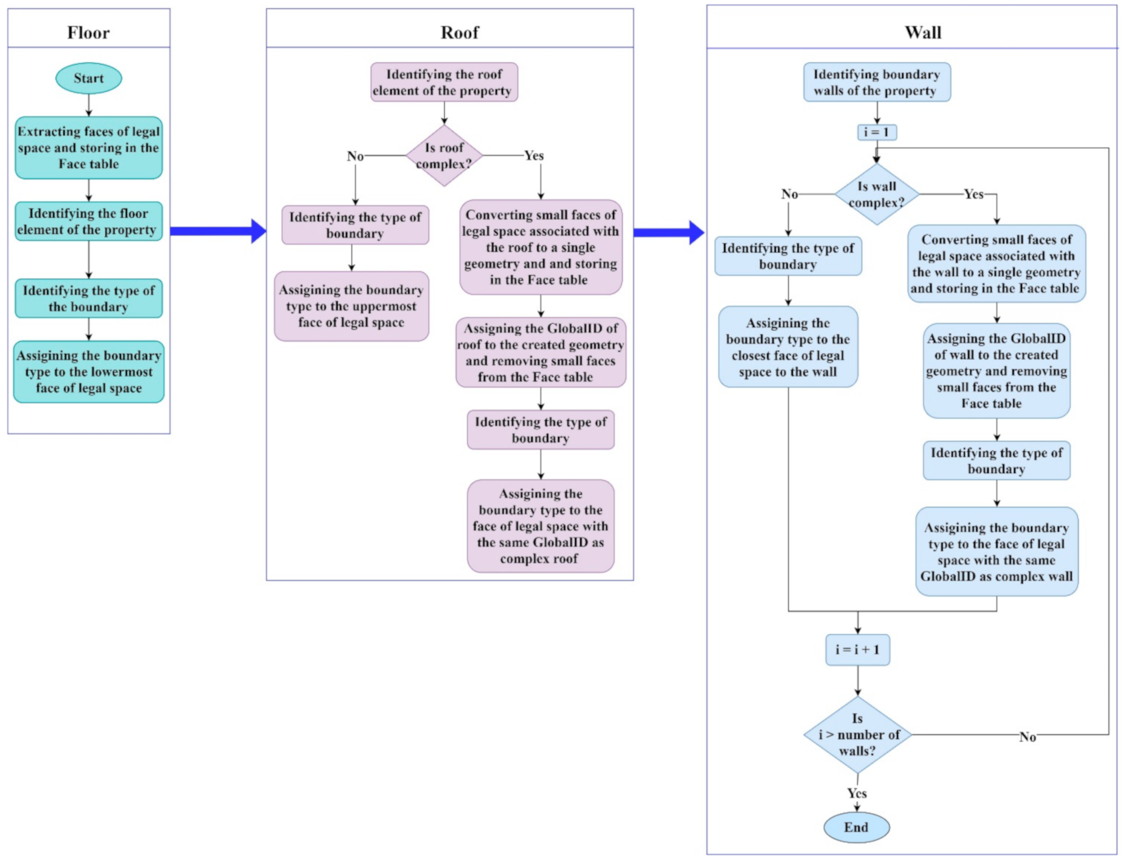
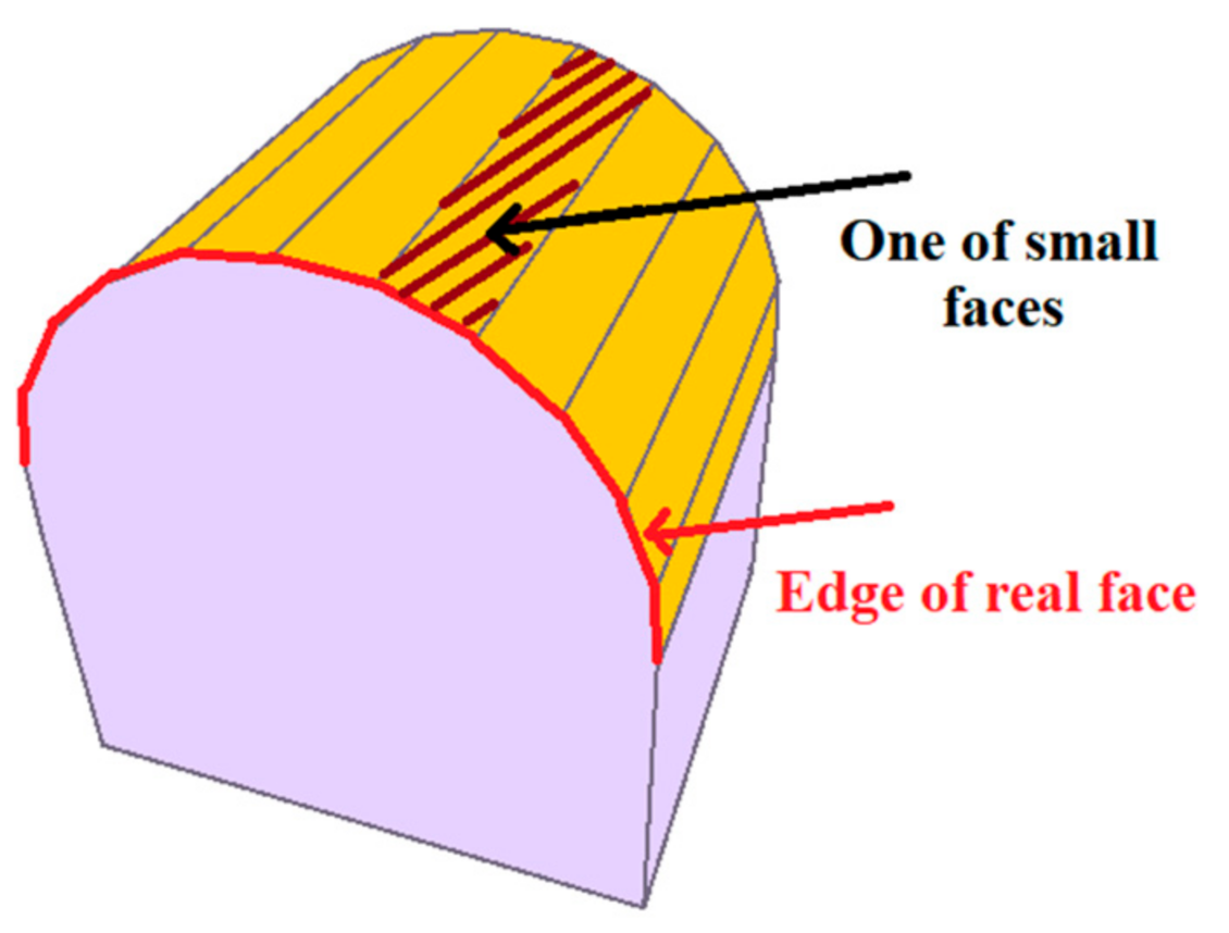
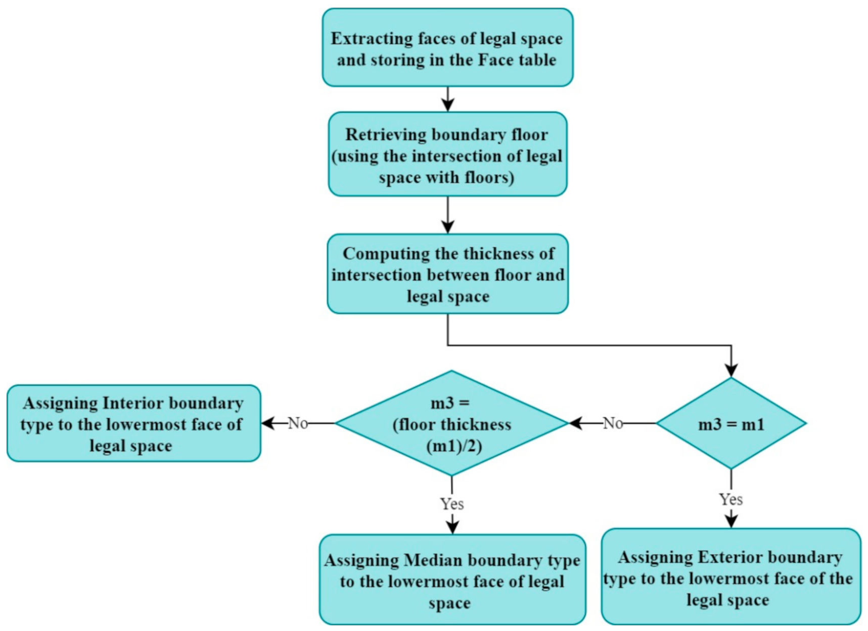
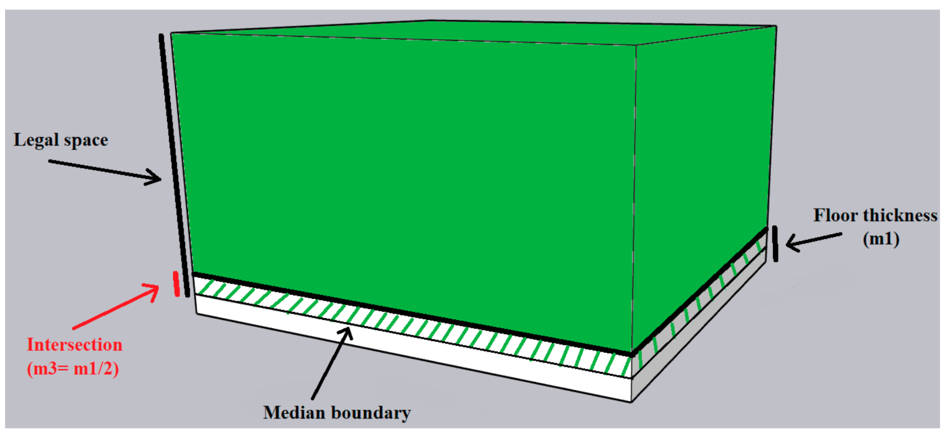
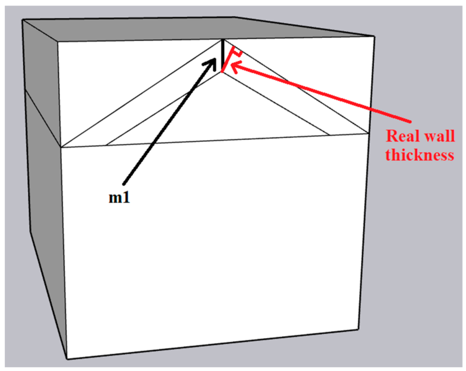
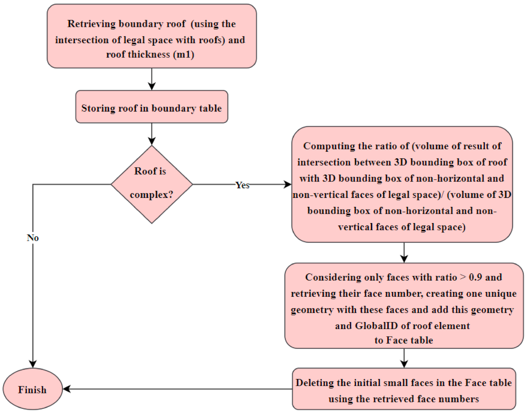
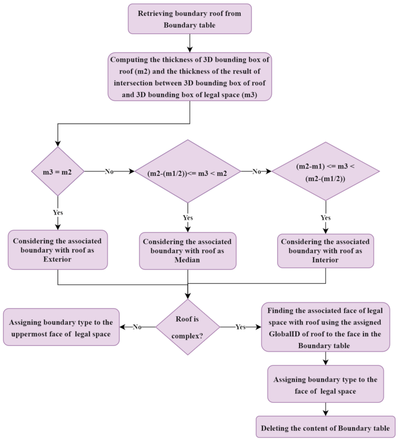
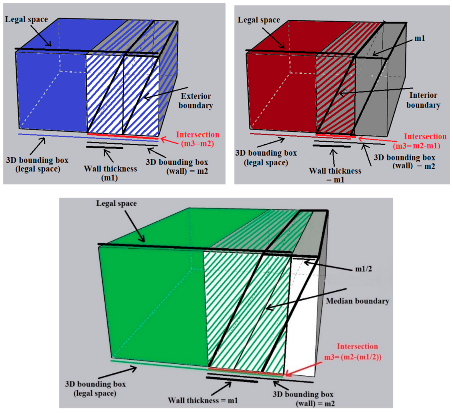
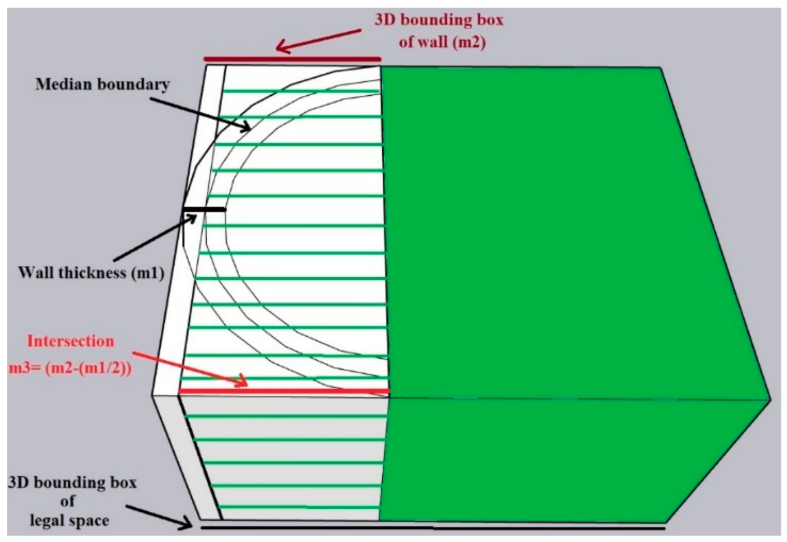
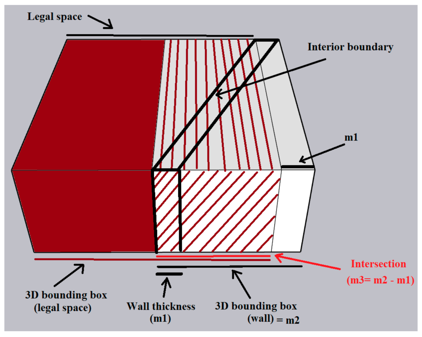
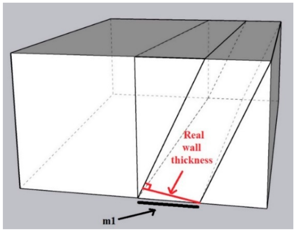
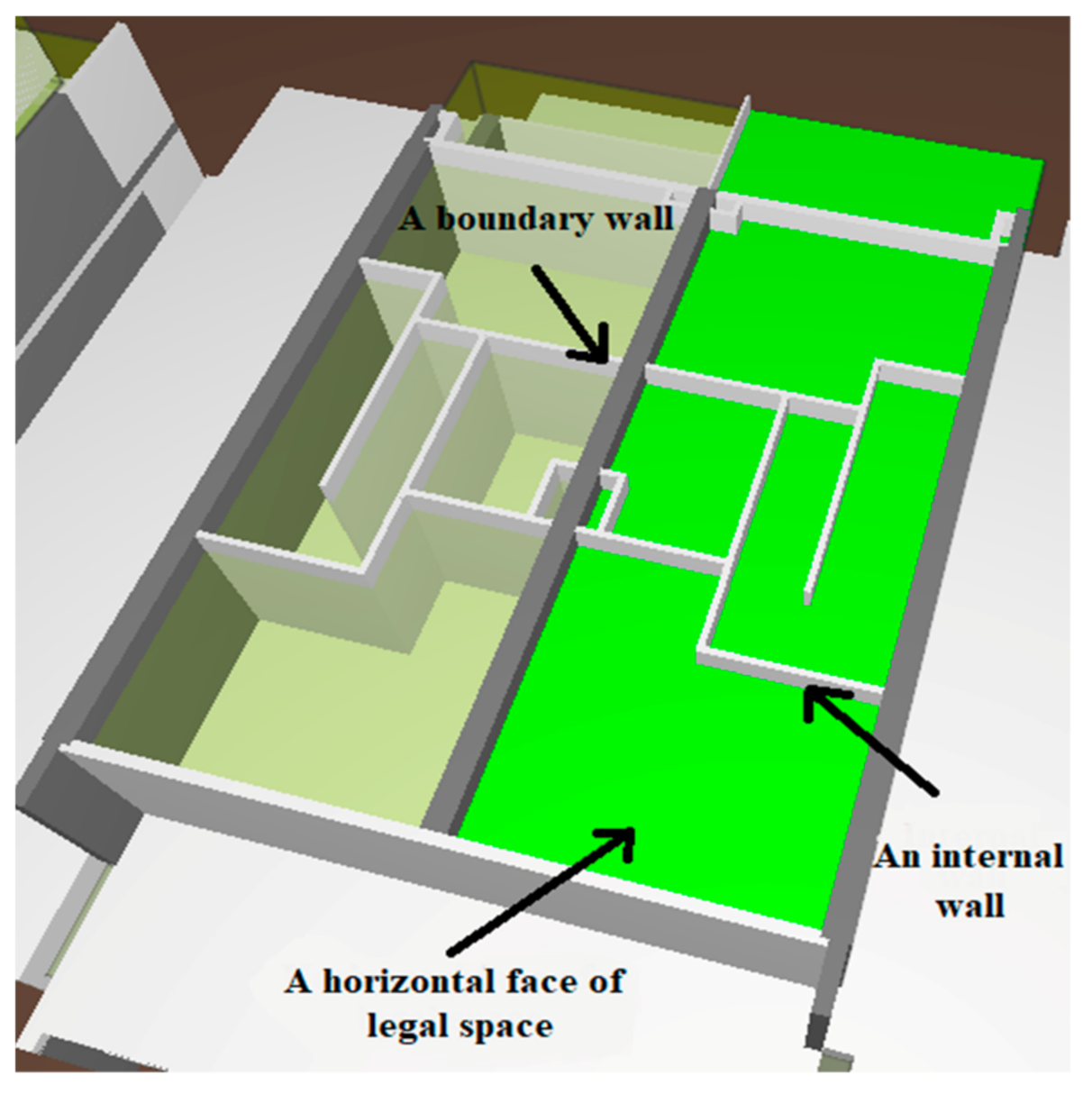
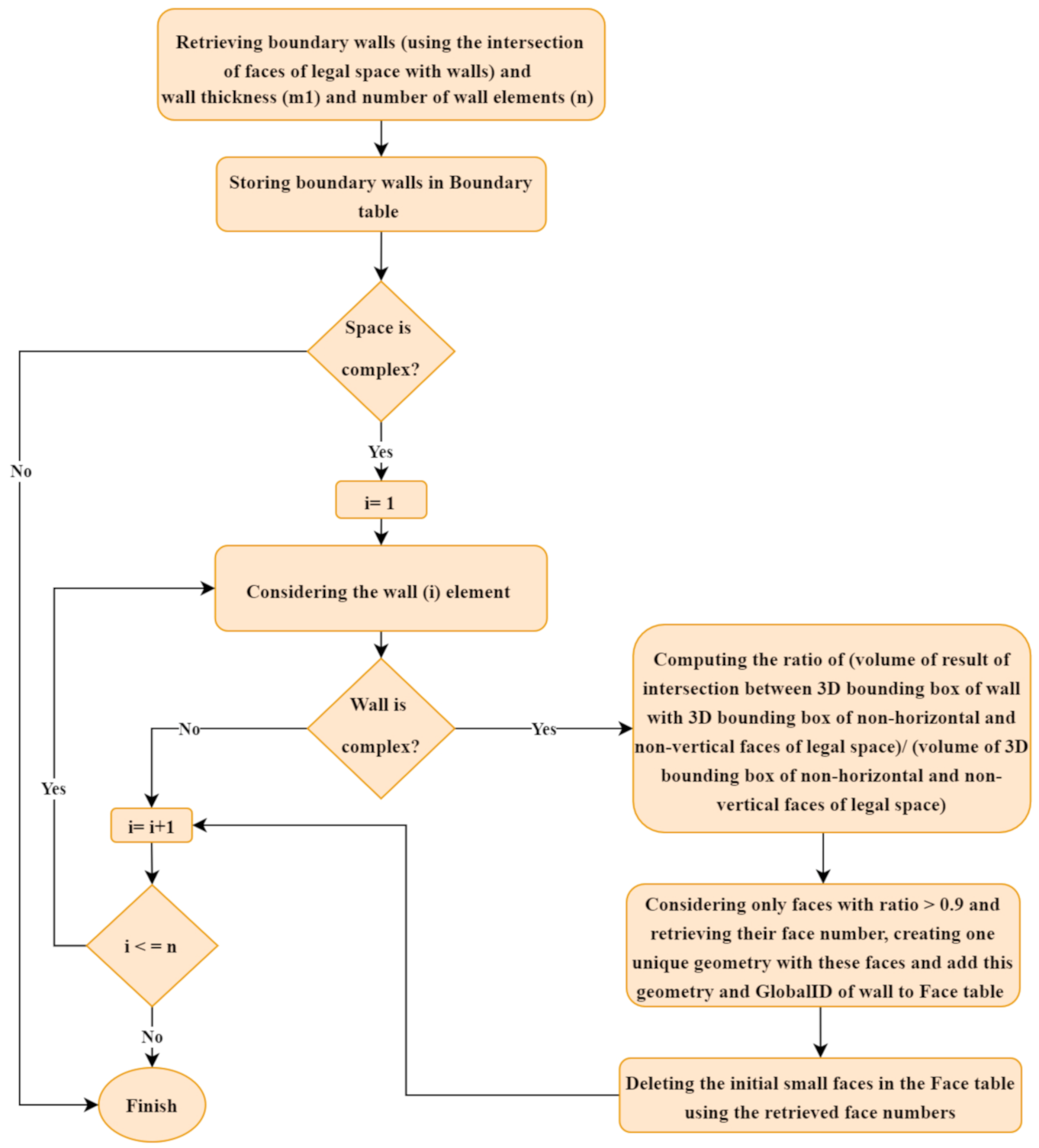
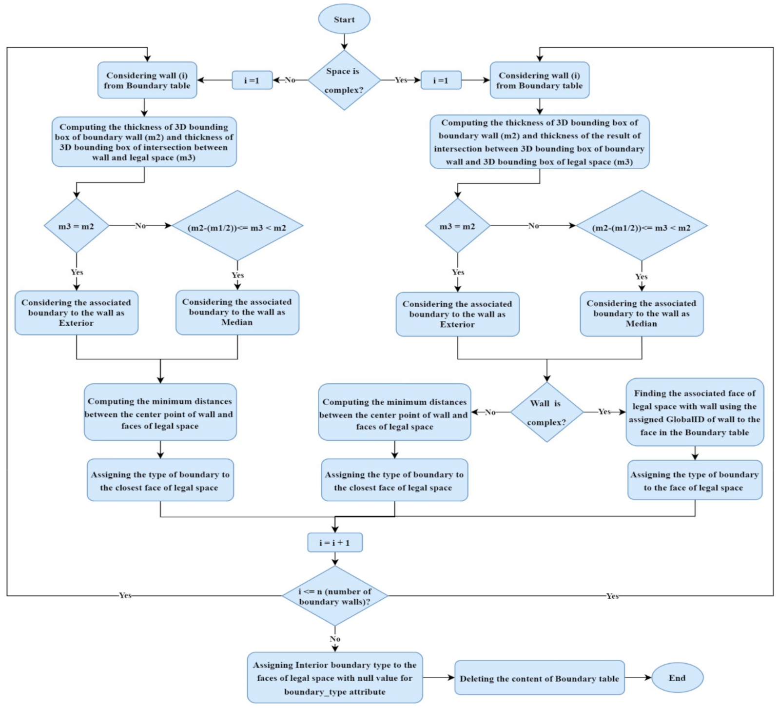
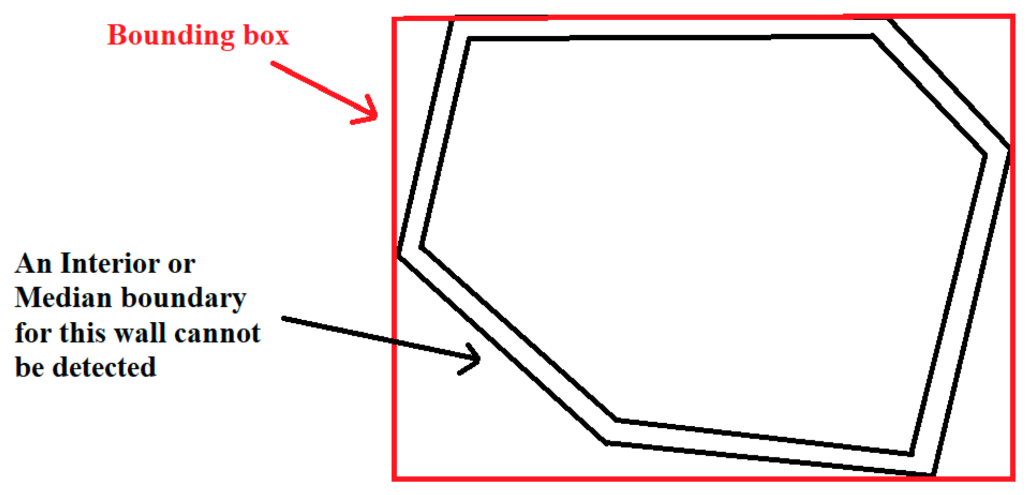
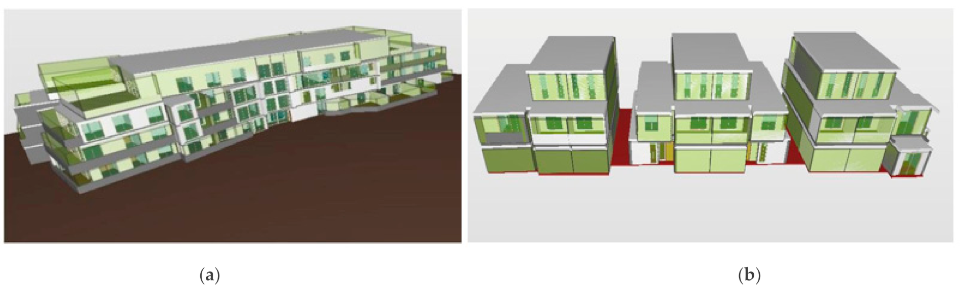
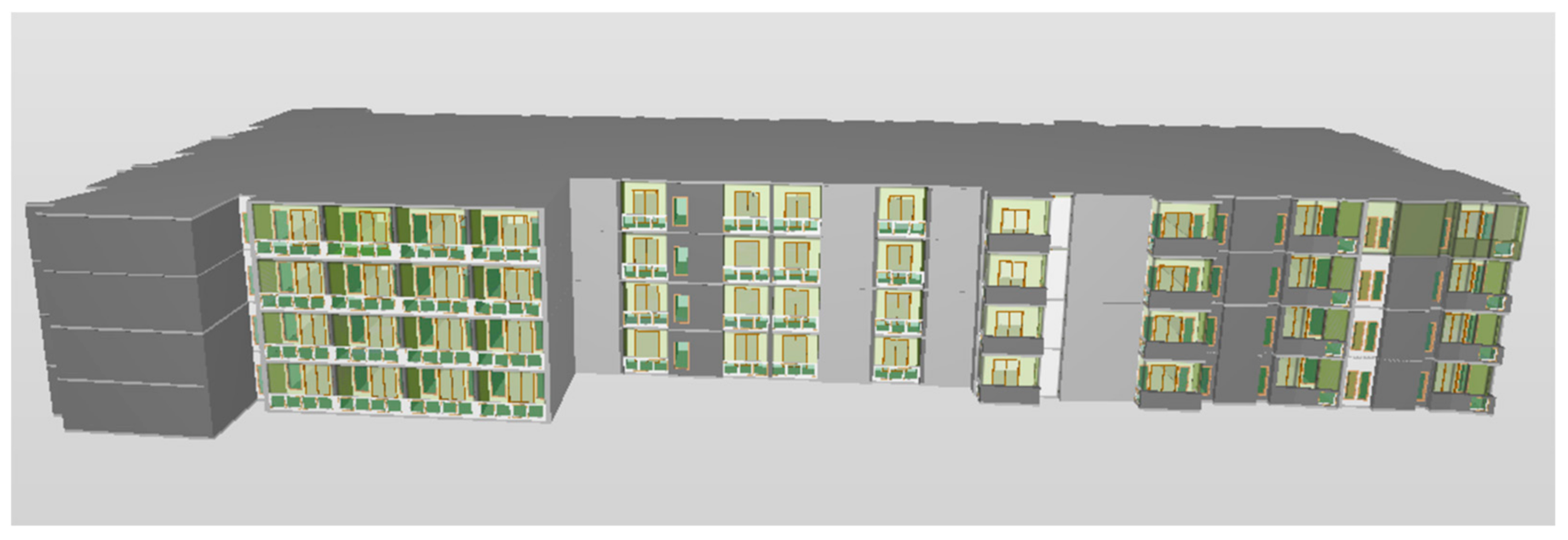
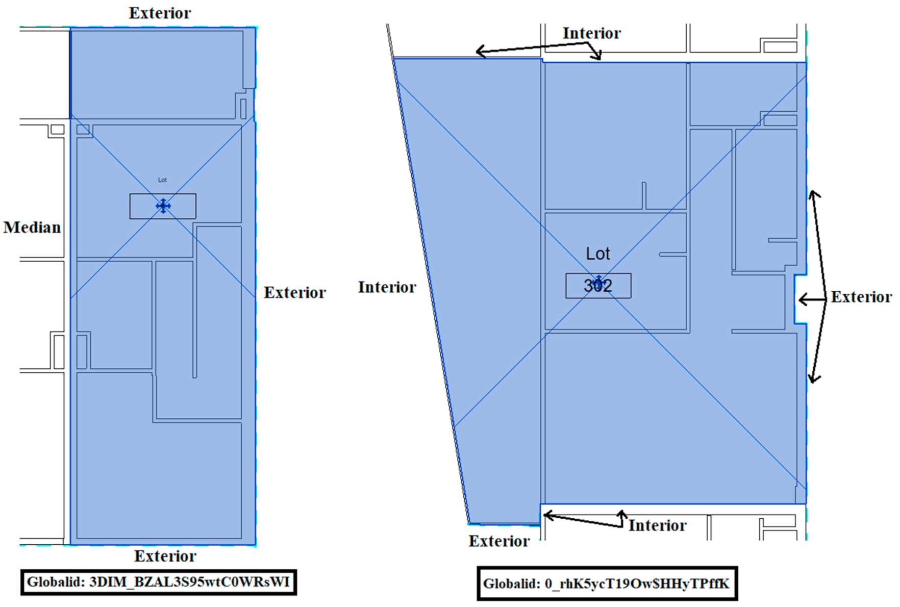
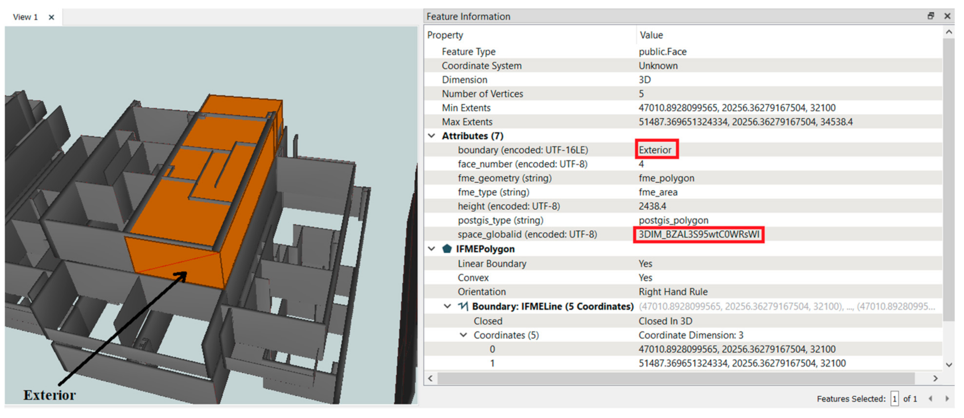
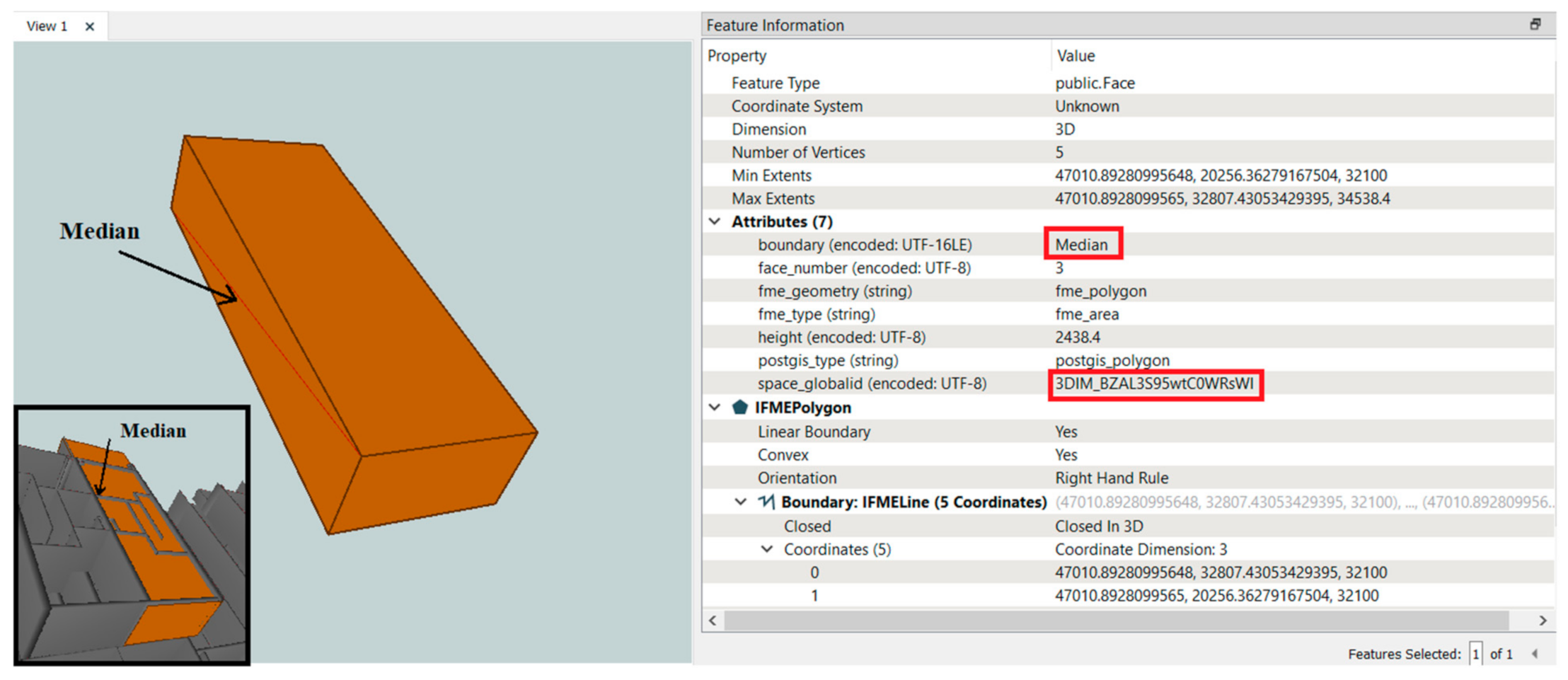
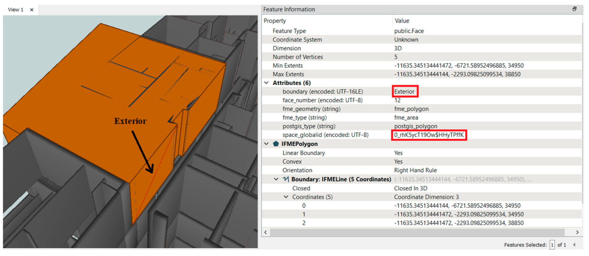
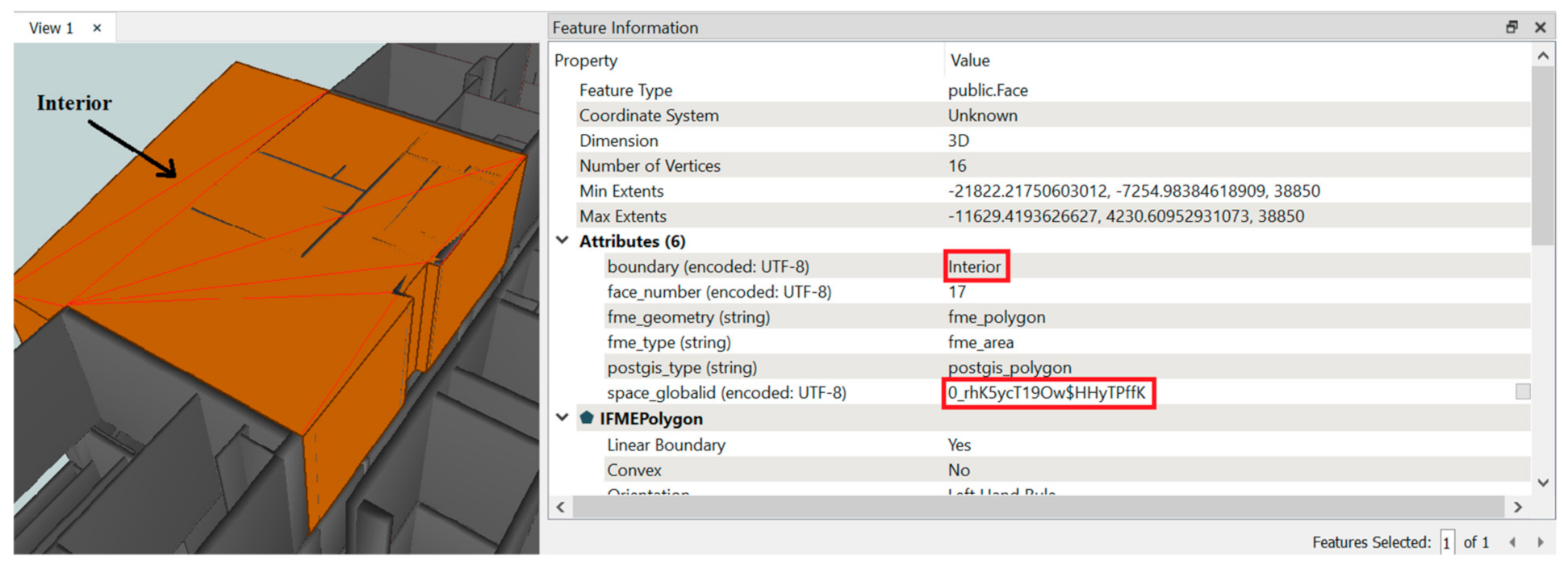
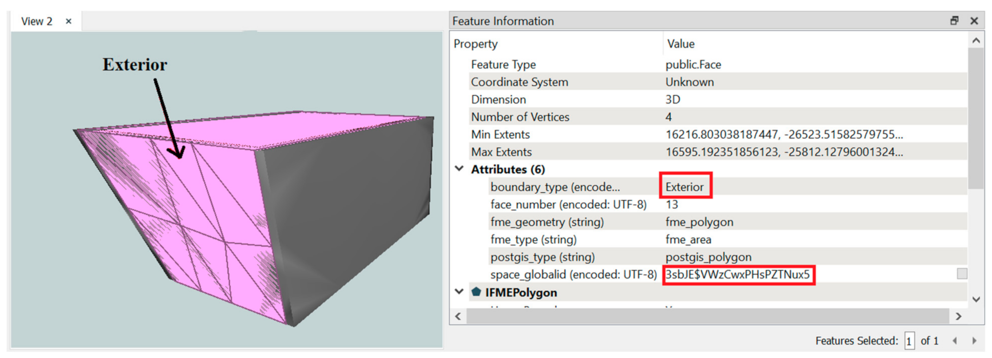
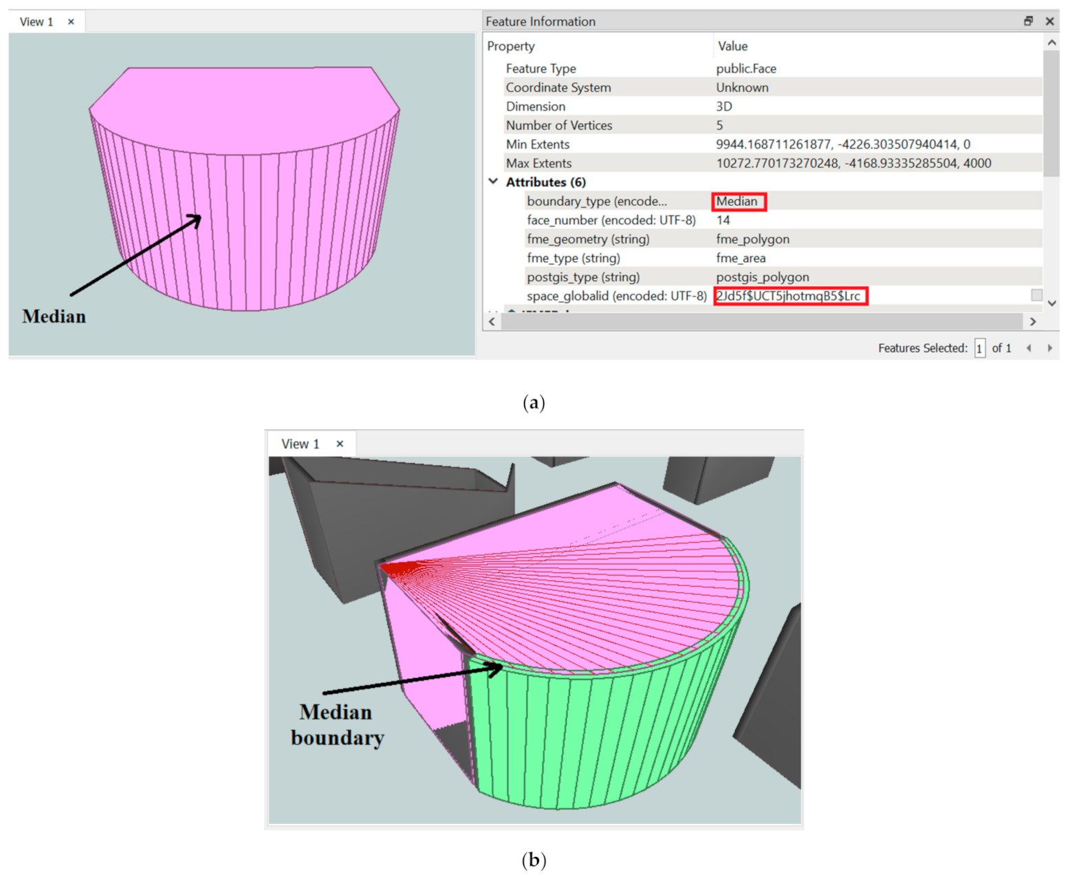
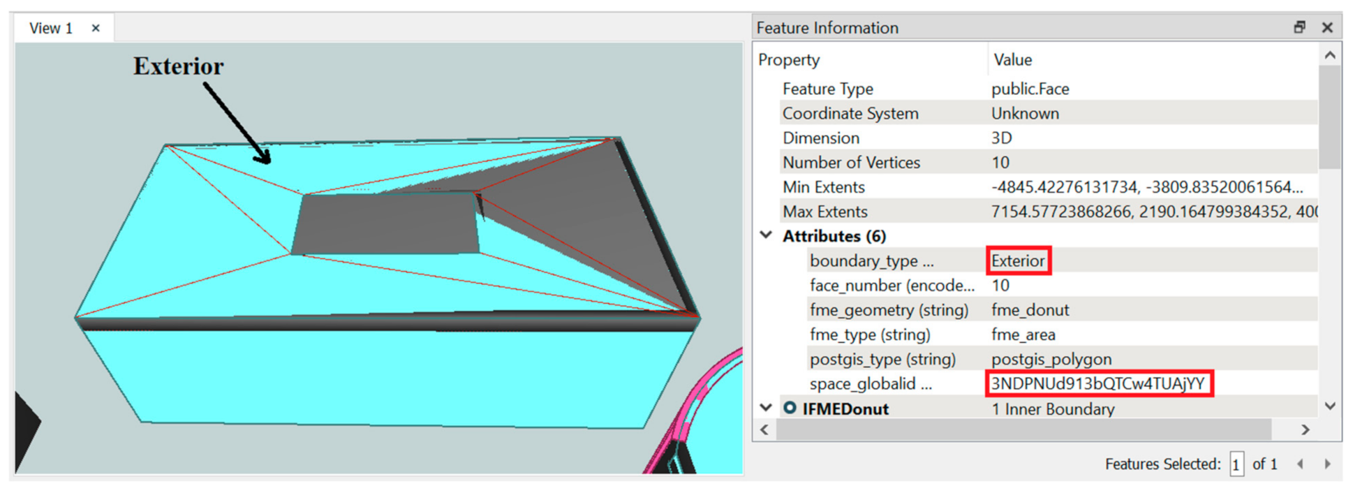
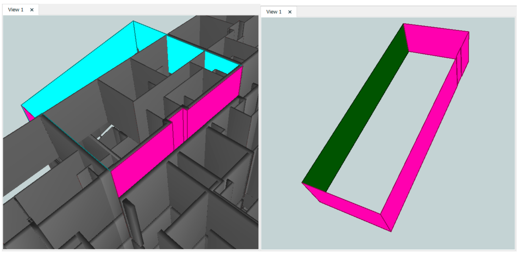
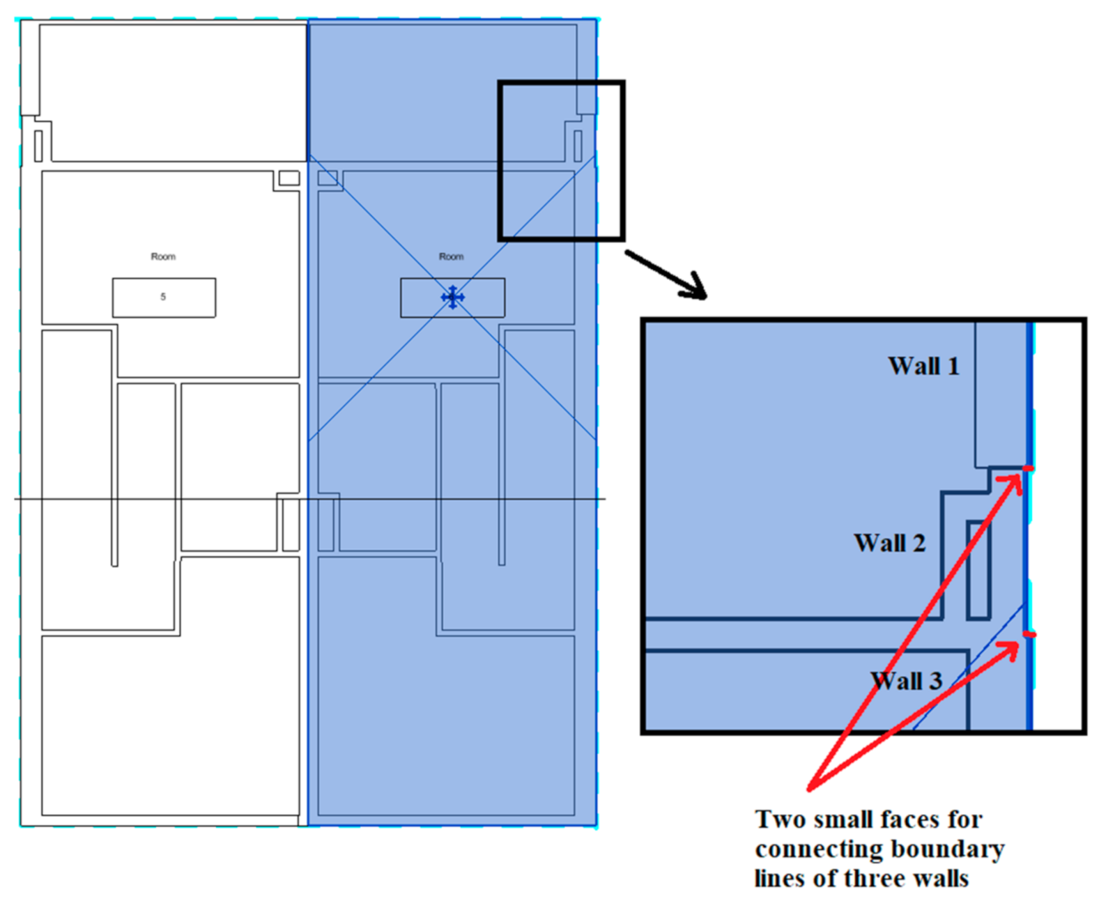
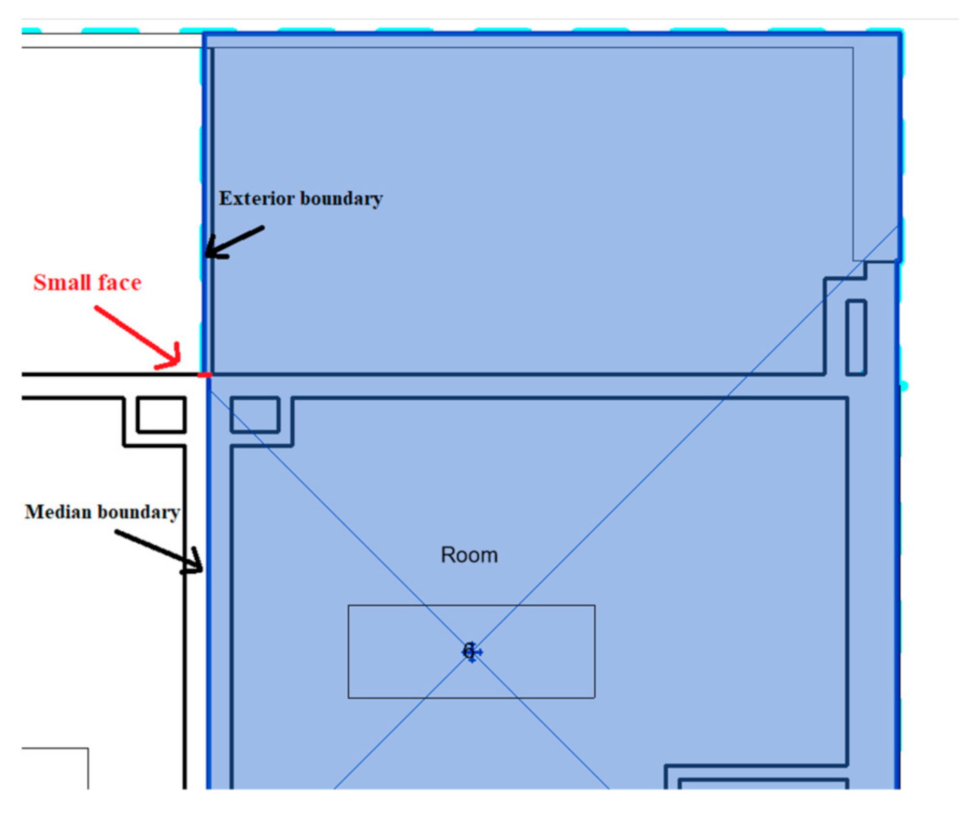
Table 1.
The required tables for performing boundary identification analysis in the database.
| Table Name | Definition | Required Columns |
|---|---|---|
| LegalSpace | Stores 3D legal spaces which define the ownerships of each property | GlobalID, Building, BuildingStorey, Geometry, Complex |
| Wall_Interior | Stores walls located inside of the building (using the Interior value for the Function property in the Revit for filtering) | GlobalID, Building, BuildingStorey, Geometry, Thickness, Complex |
| Wall_Exterior | Stores walls that create the outer surface of building (using the Exterior value for the Function property in the Revit for filtering) | GlobalID, Building, BuildingStorey, Geometry, Thickness, Complex |
| Roof | Stores ceilings and roofs | GlobalID, Building, BuildingStorey, Geometry, Thickness, Complex |
| Floor | Stores floor slabs | GlobalID, Building, BuildingStorey, Geometry, Thickness |
Publisher’s Note: MDPI stays neutral with regard to jurisdictional claims in published maps and institutional affiliations. |
© 2021 by the authors. Licensee MDPI, Basel, Switzerland. This article is an open access article distributed under the terms and conditions of the Creative Commons Attribution (CC BY) license (http://creativecommons.org/licenses/by/4.0/).
Share and Cite
MDPI and ACS Style
Barzegar, M.; Rajabifard, A.; Kalantari, M.; Atazadeh, B. Identification of Property Boundaries Using an IFC-Based Cadastral Database. Land 2021, 10, 300. https://doi.org/10.3390/land10030300
AMA Style
Barzegar M, Rajabifard A, Kalantari M, Atazadeh B. Identification of Property Boundaries Using an IFC-Based Cadastral Database. Land. 2021; 10(3):300. https://doi.org/10.3390/land10030300
Chicago/Turabian StyleBarzegar, Maryam, Abbas Rajabifard, Mohsen Kalantari, and Behnam Atazadeh. 2021. "Identification of Property Boundaries Using an IFC-Based Cadastral Database" Land 10, no. 3: 300. https://doi.org/10.3390/land10030300
Note that from the first issue of 2016, this journal uses article numbers instead of page numbers. See further details here.